BP02 玻璃破碎探测器使用说明书
BP-2002D 坚固型中文机巡检器说明书-打印版
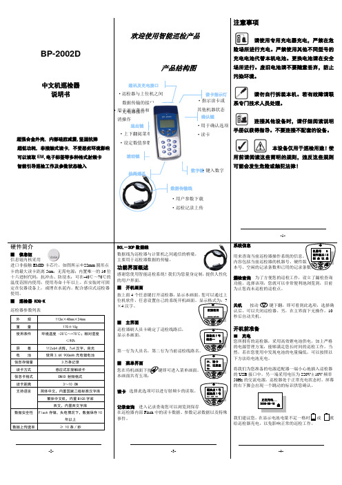
BP-2002D中文机巡检器说明书超强合金外壳, 内部硅胶减震,坚固抗摔超低功耗, 非接触式读卡, 不受恶劣环境影响 可以读取EM ,电子标签等多种格式射频卡 智能引导巡检工作及参数状态输入注意事项请使用专用充电器充电,严禁在危险场所进行充电。
严禁使用其他不同型号的充电电池代替本机电池。
更换电池请在安全场所进行。
废旧电池请不要随意丢弃,防止污染环境。
请勿自行拆装本机。
若有故障请联系专门技术人员处理。
连接其他设备时,请仔细阅读说明手册以获得指导。
不要连接不配套的设备。
本设备仅用于巡检用途!使用前请阅读这些简明的规则,违反这些规则可能会发生危险或触犯法律!硬件简介■ 信息钮 信息钮内核采用进口非接触EMID 卡芯片,如图所示Φ22mm 圆形点卡的最大读卡距离5cm ;无需电源;内置唯一的16位十六进制代码;抗冲击、防浸水;可在-40℃~70℃的温度范围内使用;使用寿命十年以上。
在安装时可固定在仪器设备上,或埋在水泥内。
配合感应式巡检器使用。
■ 巡检器 KCQ-K 巡检器参数列表外 观 112m ×48mm ×24mm重 量 170±10g使用条件环境温度 -20℃~+70℃;相对湿度≤90%屏 幕 112x64点阵,7x4汉字,背光 电 池 使用3.6V 900mAh 充电锂电池信息存储量 3万条记录 读卡方式 感应式非接触读卡 信息卡格式 EMID 射频格式 读卡距离 3~10 CM支持语言简体中文,内置国家二级标准汉字库繁体中文机,内置BIG5字库西文,内置西文字库数据安全性 Flash 存储,失电情况下,数据保存10年以上数据上传速率≥ 10条/秒BCL -30P 数据线数据线为巡检器与计算机之间通信的桥梁,主要用于巡检器数据的传输。
功能界面概述感谢您使用智能巡检系统!我们为您量身定制,提供人性化的用户界面。
■ 开机画面按上面4个任意键打开巡检器,显示本画面。
您可以通过上位机软件,任意设置自己的系统开机画面。
玻璃设备操作说明
玻璃设备操作说明一、引言玻璃设备在现代工业中应用广泛,包括玻璃熔化炉、玻璃制品成型机、玻璃检测仪器等。
正确操作玻璃设备对于生产效率和产品质量至关重要。
本文将为您提供一些关于玻璃设备操作的基本指南。
二、设备安全操作1. 佩戴个人防护设备:在操作玻璃设备之前,请确保佩戴适当的个人防护设备,如安全眼镜、耳塞、手套等。
这些装备可以保护您的视力、听力和皮肤。
2. 熟悉设备功能:在操作任何玻璃设备之前,请确保您已经熟悉设备的各种功能和控制按钮的使用方法。
如果对设备功能不太了解,请参阅设备操作手册或咨询专业技术人员。
3. 电源和电气安全:在操作玻璃设备时,请确保电源和电气连接处和开关按钮处于安全状态。
避免湿手接触电气设备,以防发生电击。
4. 工作区域清洁整齐:在操作玻璃设备时,请确保工作区域清洁整齐。
清除杂物和其他障碍物,确保操作的顺利进行。
5. 爆炸和火灾防范:在操作任何需要火焰或高温的玻璃设备时,请确保设备周围没有易燃物品。
此外,应备有灭火器并确保其工作正常。
三、玻璃设备操作步骤下面是一般玻璃设备的操作步骤示例。
1. 设备开关和启动a. 确保设备断开电源。
b. 按下设备的启动按钮,等待设备启动完成。
c. 检查操作面板上的指示灯和显示屏,确保一切正常。
2. 玻璃材料准备a. 准备所需的玻璃材料,并确保其质量达到操作要求。
b. 将玻璃材料放置在设备的指定位置或进料口。
3. 设备调整和设定a. 根据操作手册或专业人士的建议,调整设备的参数和设置。
b. 确保所设置的参数符合生产要求和产品规格。
4. 运行设备a. 启动设备并观察操作过程中的各项指示和显示。
b. 确保设备运行平稳,没有异常声音或振动。
c. 进行设备自检和监控,确保操作的安全和正常。
5. 设备停止和清洁a. 在结束操作之前,先将设备停止并断开电源。
b. 清理设备内的残留物,确保设备的卫生和下一次操作的准备。
四、设备维护和保养1. 定期保养计划:制定设备的定期保养计划,并确保按时执行。
斯蒂克防水重设式玻璃破碎报警器手册说明书
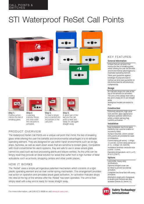
For more information, call 248-673-9898 or visit .P R O D U C T O V E R V I E WThe Waterproof ReSet Call Points are a unique call point that mimic the feel of breaking glass while offering the user the benefits and environmental advantages of a re-settable operating element. They are designed for use within harsh environments such as oil rigs, ships, factories, as well as wash down areas that are sensitive to broken glass. Compatible with most conventional fire alarm systems, they are safe to use in areas where glass cannot be used such as food processing plants and leisure centers. As the units can be simply reset they provide an ideal solution for areas that suffer from a high number of false activations such as schools, shopping centers and other public places.H O W I T W O R K SThe ‘ReSet’ uses a simple yet ingenious patented mechanism which consists of a rigidplastic operating element and an over center spring mechanism. This arrangement provides real action on operation and simulates break glass activation. An activation indicator drops into view at the top of the window after the ‘ReSet’ has been operated. The unit is then simply reset with a key and is ready for reuse straight away.K E Y F E AT U R E SGeneral Information· Unique manual call point that mimics the feel of breaking glass whilst offering the user the benefits and environmental advantages of a resettable operating element.· Three year guarantee against breakage of polycarbonate innormal use (one year guarantee on electromechanical and electronic components).Desig n· An indicator drops into view at the top of the window on activation. The unit is then simply reset with a key and is ready for re-use straight away.· Waterproof models are tested to IP67.Construction· E xtremely attractive, high value look and feel: glass appearance maintains operator deterrence, whilst a visible warning flag confirms activation.Installation· Easy installation due to no glass elements that could be broken or incorrectly fitted.· Surface mounted, 20mm conduit entry points are provided for ease of installation.· Current rating (all series) - 3 Amps 12-24V DC, current rating (series 02 & 11) - 3 Amps 125-250V AC.· Installation terminal conductor size 0.5mm - 2.5mm.· Operating temperature -20°C (-4°F) to 65°C (149°F).Options· L ow profile, heavy-duty terminations.· Optional integral cover can be fitted to prevent accidental activation.· Complete functional test with every activation.· Alternative single pole changeover & double pole versions are also available (Series 02, Series 11).STI Waterproof ReSet Call PointsStep 1:Positive action - mimics the feel of breaking glass.Step 2:A warningindicator drops into view when the call point is activated.Step 3:To reset a simple key is inserted into the bottom of the call point.Step 4:A quick turn of the key and the call point is reset and ready for use againstraight away.STI Waterproof ReSet Call PointsDimensions and Technical Information© 2007-2022 Safety Technology International Ltd. WRP2_WaterproofReSetCallPoints_Rev1119Denotes a ReSet call point that will interface with most conventional fire alarm systems. It is fitted with two internal resistors 470 (R1) and 680 (R2) ohms. These are easily accessed through the installer terminals as illustrated.Denotes a ReSet call point that is fitted with a single pole changeover switch both the normally open and normally closed contacts areeasily accessed through the installer terminals as illustrated.Denotes a ReSet call point that incorporates two independentsingle pole changeover switches providing double polechangeover contacts. Easily accessed through the installer terminals as illustrated.Switch arrangements shown with ReSet in standbySeries 01*Series 02Series 11Covers AvailableElectrical Arrangement OptionsUniversal Stopper ® - Surface mountSTI-13120FR-BREAKWeather Stopper II ® - Surface mountSTI-3150-BREAKThis unique device is ideal for extending the life and reliability of weather exposed devices, such as larger manual call points. It offers protection against harsh environments and conditions both outside and inside, as well as preventing tampering, vandalism and damage from accidental or malicious operation.These indoor and outdoor low profile or dome polycarbonate covers protect devices such asmanual call points, emergency buttons and dual action pull stations etc., without restricting legitimate operation. The versatile coveroffers excellent protection against physical damage (both accidental and intentional), dust and grime aswell as severe environments inside and out.0905-CPR-00439Designed to fit directly to the cover of the STI Call Points (Indoor/Outdoor), preventing accidental activation.Integral CoverSTI-CI• ISOLATION SWITCH • PANIC ALARM • POOL ALARM • SMOKE VENT *only available with red modelsSupplied with all models (except red & green) unless -CL is specifiedAdd -CL to desired product code (available for all colors)Supplied with all red models as standard, unless -CL is specified Supplied with all green models as standard, unless -CL is specifiedCUSTOM LABEL = Max, 2 lines, 10 characters per line including spacesHeight (mm)Width (mm)Depth (mm)WRP2908972D I ME NS I O NSSTI-RP-K/10 Reset Key (pack of 10)。
玻璃破碎探测器最终版

目录第一章入侵报警系统2一.系统概述2二.设计原则2三.设计说明3四.设计目标3五.系统架构4六.前端设备61.探测器选型62.玻璃破碎探测器6七.中心设备71. 6160控制键盘9八.系统功能9第一章入侵报警系统一. 系统概述建行新建办公楼为B、C两座,其中B座为地下4层(包括夹层)地上17层(包括屋顶机房层),C座为地下2层地上5层。
B座为工作区全部为机房设备间,C座为生活区和办公区。
入侵报警系统是采用物理方法和电子技术,自动探测发生在布防监测区域内的侵入行为,产生报警信号,并辅助提示值班人员发生报警的区域部位。
显示可能采取的对策。
在布防条件下能够自动探知所发生的侵入行为是防盗报警系统成功的关键。
在此,各种各样的入侵探测器发挥着至关重要的作用,它们时刻注视着所发生的一切,一旦发生入侵行为,它们之中至少要有一个能够产生触发报警信号,实时地传送给报警接收控制器。
二. 设计原则该系统是一个既完整又独立的系统。
系统在设计时根据“严密、合理、可靠、经济、完善”的设计思想,努力做到安全、周密,兼顾其它。
系统设计时遵循以下原则,以达到最佳效果和最优性能价格比。
(1)技术先进性和可靠性本系统设计严密、布局合理,能与新技术新产品接轨,采用当前先进的、具有很高可靠性的系统。
(2) 经济性和完整性本系统设备齐全、功能完善、综合管理。
系统建设始终贯彻面向应用,注重实效的方针,坚持以客户需求为核心,注重良好的产品性价比;同时,为保证系统在实际工作中更好的发挥作用,我们的设计从整体上考虑系统技术手段的选择和前端设备的分布,确保系统能在各个流程、安全防范工作的各种关键环节实施有效地控制。
(4) 开放性和标准性为满足系统所选用的技术和设备的协同运行能力,系统采用标准化设备,并在开发上注意层次的切割与封装,允许其他应用的接入、调用以及不同厂商标准化设备的兼容,从而使系统具有开放性。
三. 设计说明防盗报警系统主要由前端的主动红外对射探测器等报警探测器、现场的报警信号接入模块、中心的控制主机键盘及多媒体工作站等设备构成。
玻璃破碎探测器

玻璃破碎探测器
1、玻璃破碎探测器功能说明
外形美观大方,安装方便探测器的监测范围为一整个房间(与窗户多少无关)灵敏度连续可调可以根据环境情况设定一个最佳工作点,防误报而不减灵敏
度阻燃外壳。
监测当玻璃破碎时发出报警,防止人为破坏和非法入侵。
产品广泛适用于平面、强化和层面玻璃。
探测器适用于对楼宇、大厦、宾馆、珠宝店、银行等需要监测到玻璃破碎就报警的各种场所。
2、参数说明
数字处理器:12/8bits8MHz
灵敏度:连续可调
保护范围:最高灵敏度为9米距离
安装位置:天花或墙壁,接近或面对玻璃窗
抗干扰:抗无线电及电磁波
玻璃窗大小:任何大小玻璃
警报指示:红色LED亮保持3秒
LED指示:绿LED亮-探测,红色LED亮-警报
金属护罩:抗射频干扰
警报输出:常闭,28Vdc0.15A
防拆开关:常闭,盖被拆除开路,0.15A,28Vdc
电源输入:9-16Vdc,17mA
工作温度:-20℃至50℃
工作湿度:95%
重量:100g
尺寸:90x66x25mm
3、安装调试说明
一个合适的安装位置是探测器达到最佳工作状态的关键。
建议选择天花板或玻璃或玻璃旁边或对面,要避免探测器感应到发出噪声的物体,如电铃、风扇、压缩机或声音较大的设备,以防噪声干扰造成误报。
安装位置应保证探测器内收声筒无阻挡地直接朝向要保护的玻璃表面上,同时玻璃表面要在最佳探测角度范围内(见下图)。
探测器具有灵敏度调节功能,根据不同的现场环境,调节其反应灵敏度,以降低外界对探测器的干扰,最终达到较理想的监测效果。
玻璃破碎检测器
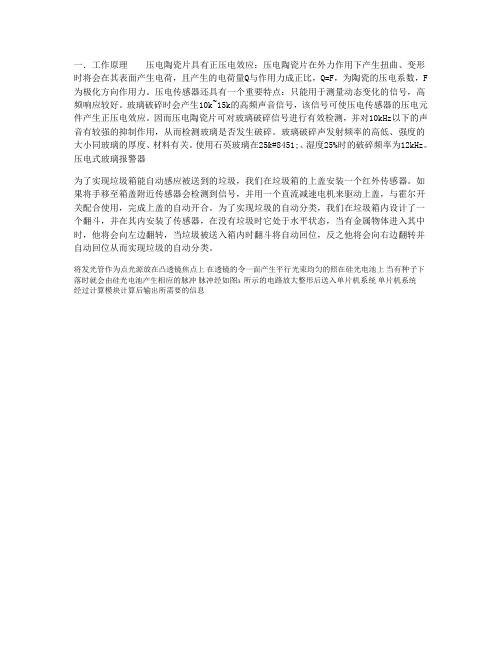
一.工作原理压电陶瓷片具有正压电效应:压电陶瓷片在外力作用下产生扭曲、变形时将会在其表面产生电荷,且产生的电荷量Q与作用力成正比,Q=F,为陶瓷的压电系数,F 为极化方向作用力。
压电传感器还具有一个重要特点:只能用于测量动态变化的信号,高频响应较好。
玻璃破碎时会产生10k~15k的高频声音信号,该信号可使压电传感器的压电元件产生正压电效应。
因而压电陶瓷片可对玻璃破碎信号进行有效检测,并对10kHz以下的声音有较强的抑制作用,从而检测玻璃是否发生破碎。
玻璃破碎声发射频率的高低、强度的大小同玻璃的厚度、材料有关。
使用石英玻璃在25℃、湿度25%时的破碎频率为12kHz。
压电式玻璃报警器
为了实现垃圾箱能自动感应被送到的垃圾,我们在垃圾箱的上盖安装一个红外传感器。
如果将手移至箱盖附近传感器会检测到信号,并用一个直流减速电机来驱动上盖,与霍尔开关配合使用,完成上盖的自动开合。
为了实现垃圾的自动分类,我们在垃圾箱内设计了一个翻斗,并在其内安装了传感器,在没有垃圾时它处于水平状态,当有金属物体进入其中时,他将会向左边翻转,当垃圾被送入箱内时翻斗将自动回位,反之他将会向右边翻转并自动回位从而实现垃圾的自动分类。
将发光管作为点光源放在凸透镜焦点上, 在透镜的令一面产生平行光束均匀的照在硅光电池上, 当有种子下落时就会由硅光电池产生相应的脉冲, 脉冲经如图3 所示的电路放大整形后送入单片机系统, 单片机系统
经过计算模块计算后输出所需要的信息。
2520 玻璃破碎探测器 安装手册

2520 安装说明书
2.4.B
四、测试:
按下测试按钮,黄色测试灯会亮,使用2520 GBS玻璃破 碎模拟器作测试,测试结束后再按一次测试按钮,黄色测 试灯灭,退出测试; 另外2520在测试后5分钟会自动退出测 试状态.
五、指示灯状态
工作模式
绿(状态)
红(报警) 黄(测试)
测试
亮
灭
亮
测试中报警
灭
亮
亮
七、指标:
参数
最小值 最大值
输入电压
11.5 18
输入电流
20
30
输出继电器触点
24
容量
-
1
工作温度
0
55
报警延时
3
-
探测范围
-
8
单位
V mA VDC A ℃ 秒 -
※最小保护玻璃面为26平方厘米.
2520 玻璃破碎探测器安装手册
一、概述:
2520是应用微处理器的玻璃破碎探头,它可检测到玻 璃破碎的声音及撞击,并对该两种信号分析后才作出报 警,探头灵敏度经预置好,因此不必再作调整,并且探头的 误报及漏报的可能性较低。
二、应用:
2520可在8米范围内探测到1/8"和1/4"平板玻璃及 1/4"钢化和薄板玻璃破碎的信号并作出报警.
常规 亮(环境噪音时闪)
灭
灭
报警
灭
亮(3.5秒)
灭
报警记忆 亮(环境噪音时闪)
亮
灭
低电压
灭
每3.5秒闪2次 灭
注:状态灯可通过跳线开关来关闭
六、性能:
2520 安装说明书
2.4.B
规格: 电路保护: 报警输出Байду номын сангаас 指示灯:
玻璃破碎探测器(机房监控)技术参数设计说明
玻璃破碎探测器(机房监控)技术参数设计说明玻璃破碎探测器(机房监控)技术参数设计说明品牌:KITOZER(开拓者)产品编号:91113482416产品名称:玻璃破碎探测器规格:声音和震动监测产品备注:玻璃破碎时产生报警,防止非法入侵产品类别:集中监控用途:玻璃破碎时产生报警,防止非法入侵。
能探测的玻璃种类包括钢化玻璃、强化玻璃、层化玻璃。
适用于宾馆、商店、图书馆、珠宝店、仓库以及其它对玻璃及窗户破碎需要报警的场所。
双技术监测:单用声音监测电路来监测玻璃破碎非常容易因钥匙、电扇、铃声等与玻璃破碎声频率相近的声音引起误警。
有的设备应用弯曲技术,但这需要在玻璃破碎前有足够的因玻璃弯曲发出的低频波,问题是大多数小型玻璃在破碎之前并不弯曲。
ADEMCO的信号处理电路对玻璃破碎时发出的声波(4 ~ 5Khz)和通过固体(如砖块、木头、混凝土等)传播的冲击波(200Hz)进行分析,从而减少误警几率。
提供简便、灵活的安装方式,其声音和震动监测灵敏度完全可调,许多品牌都不提供灵敏度调整或只提供声音灵敏度调整,这需要在安装时不断调整位置。
而SG-380则可以安装在任何你想安装的地方(8米的保护范围)规格:声音和震动监测声音和震动灵敏度都可调 SMD贴片安装防止RFI干扰防拆安装简便监测玻璃的类型:普通平板玻璃、冶炼玻璃、金属玻璃、薄片玻璃等保护范围:8米指示灯:绿色(震动)、红色(报警)报警记忆:可选报警记忆锁定输入电压:正常12V (10 ~ 16VDC)最大电流:30mA报警继电器触点:SPDT,24VDC最大1A环境温度:0℃~50℃环境湿度:95%以下安装位置:为了使探测器处于最佳工作状态,必须选择一个合理的安装位置。
在紧邻或正对被测玻璃的天花板或墙上寻找安装范围。
避免靠近像铃、风扇、压缩机和大声音的噪音物体。
确定探测器准确的安装范围和方向,以确保探测器的麦克风对被测玻璃有一个直接和无障碍的观察。
BJ-Ⅱ崩解时限测定仪操作规程编号占用
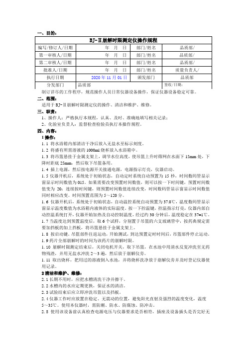
一、目的:二、范围:适用于BJ-Ⅱ崩解时限测定仪的操作、清洁和维护、维修。
三、职责:1、操作人:严格执行本规程,认真、及时、准确地填写相关记录;2、化验室负责人:监督检查检验员执行本操作规程。
四、内容:1操作:1.1 将水浴箱内部清洁干净后放入无盐水至标示刻度。
1.2 将盛有所需溶液的1000ml烧杯放入水浴箱中。
1.3 将吊篮悬挂于金属支架上,调节水位高度,使吊篮上升时筛网在水面下15mm处,下降时距底25mm,然后取下吊篮备用。
1.4 插上电源,然后按电源开关接通电源,电源指示灯亮,仪器启动。
1.5仪器开机后,系统处于初始状态,自动定时系统自动预置为15秒,时间数码管显示窗显示时间数值为015。
如果需要改变预置时间数值,则可以按一下时间键,预置时间数值变为20;连续按时间键,则预置时间数值连续改变,时间数码管显示窗显示时间数值同时相应改变。
时间预置范围为5~120分。
1.6 仪器开机后,系统处于初始状态,自动温控系统自动预置为37.0℃,温度数码管显示窗显示温度数值为水浴箱内液体的实际温度。
按一下控温键,控温指示灯亮,仪器内部自动控温系统打开,仪器开始加热及自动控制温度,经过约30分钟后,温度稳定在37±1℃。
1.7当温度达到预置温度后,取6个试样,分别置于吊篮的六支玻璃管中,按药典规定需要加挡板的加上挡板,将吊篮悬挂于金属支架上。
1.8 按启动键。
吊篮部件往返运动,开始测试,到达预置定时时间后,吊篮部件停止运动。
1.9药片全部崩解时的时间为该药片的崩解时限。
1.10崩解时限测定结束后,关闭电机开关,取下吊篮,在水池中用清水反复冲洗至无药物残渣,并用无盐水冲洗2~3遍,然后放于崩解仪旁。
1.11取出烧杯,把用过的溶液倒入水池,并将烧杯洗净放于崩解仪旁并及时登记仪器使用记录。
2清洁和维护、维修:2.1长期不用时,应把水槽清洗干净并擦干。
2.2水槽内的水应定期更换,保证水的清洁。
2.3试验结束后应立即冲洗吊篮以及挡板。
BP-2002B坚固型巡检器使用说明-打印版
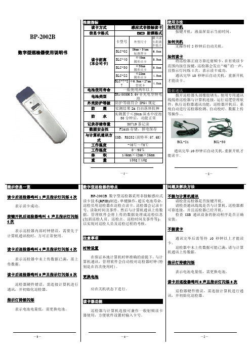
BP-2002B数字型巡检器使用说明书性能指标读卡方式感应式非接触读卡信息卡格式EMID 射频格式读卡距离(本公司卡)卡型号外型尺寸最大读卡距离不低于BLC-02 86mm×54mm标准厚卡6.0cmBLC-40 Φ40mm圆形点卡5.5cmBLC-30 Φ30mm圆形点卡5.0cmBLC-22 Φ22mm圆形点卡4.5cmBLC-7-27Φ6.5mm×27mm管状卡4.0cm电池使用寿命一般使用两年以上电池类型ER14505M 3.6v非充电型锂电池外壳防护等级防护等级符合IP54规定防震实测结果2m自由落体抗摔防水实测置于≤20cm深水中浸泡30分钟后,功能正常记录存储容量30719条记录数据安全性Flash存储,掉电保存与计算机通讯方式USB,RS232(波特率:57.6K)工作温度-40℃~70℃工作湿度0~95℅体积146mm×42mm×26mm重量180g±10g使用方法如何开机按键开机,液晶屏显示当前时间。
如何关机无操作时5秒钟后自动关机。
如何读卡将巡检器正前方靠近射频卡,在有效读卡范围内按住按键,巡检器会发出“嘀”的一声,且指示灯闪烁4次,表示读卡成功。
通讯完毕10秒钟后自动关机,重新开机才能读卡。
数据通讯拨开巡检器头部橡胶堵头,使用专用通讯线线将巡检器与计算机连接,运行巡逻管理软件,执行巡检器通讯功能,巡检器开机后,系统自动进行巡检器检测、自动校时、数据上传等操作。
、BCL-21 BCL-30通讯完毕10秒钟后自动关机,重新开机才能读卡。
提示信息一览读卡后巡检器鸣叫1声且指示灯闪烁4次表示读卡成功。
按键开机后巡检器鸣叫4声且指示灯闪烁4次表示巡检器内部时钟错误,需要先于计算机通讯校时,方可正常使用。
读卡后巡检器鸣叫4声且指示灯闪烁4次表示巡检器中未上传数据已满,需上传数据。
读卡后巡检器鸣叫8声且指示灯闪烁8次巡检器硬件错误,需连接计算机进行通讯,并初始化巡检器。
破碎机操作说明范文

破碎机操作说明范文一、安全须知1.在使用破碎机之前,务必仔细阅读本操作说明,并确保了解并理解其中的所有安全须知。
2.在使用破碎机之前,应确保操作人员已接受过相关培训,并熟悉破碎机的使用方法。
3.在操作破碎机时,应穿着合适的工作服和防护装备,包括安全帽、护目镜、耳塞、手套等。
4.遵循所有国家和地区的安全规定和标准。
二、设备检查1.在使用破碎机之前,应进行设备检查,确保破碎机的各项部件完好无损。
2.检查所有电线和插头,确保其正常工作,并没有损坏或断裂。
3.检查破碎机的刀片和刀盘,确保其锋利且无杂质。
4.检查所有电动机的安装是否牢固。
5.检查并确保破碎机的所有安全装置都正常工作。
三、操作步骤1.将要处理的物料放入破碎机的进料口。
2.打开破碎机的电源开关,并调整破碎机的参数,如转速和切割尺寸。
3.确保破碎机的运转方向正确,不要逆转。
4.按下启动按钮,使破碎机开始运行。
5.当破碎机运行时,应密切观察其工作状态,确保其正常运转。
6.当处理物料进入破碎机后,可以适时调整破碎机的参数,以获得所需的切割效果。
7.如果出现异常情况,如破碎机停止工作或轧机堵塞,请立即停止运行破碎机,并检查问题所在。
8.在长时间使用破碎机后,应对其进行冷却和维护,以确保其正常工作。
四、维护保养1.在使用完破碎机后,应将其清洁干净,并确保其外表没有物料残留。
2.定期检查破碎机的刀片和刀盘,并进行清理和维护。
3.检查破碎机的电线和插头,确保其没有损坏或断裂。
4.定期检查破碎机的电动机和传动装置,并确保其正常工作。
五、注意事项1.使用破碎机时,应避免长时间连续工作,以避免设备过热。
2.不要将不符合要求的物料放入破碎机,以免损坏设备。
3.不要在破碎机正常运转时打开破碎机的安全装置,以免造成伤害。
4.在调整破碎机参数时,应保持手部远离刀片和刀盘,以免受伤。
5.在清洁破碎机或进行维护保养时,应先切断电源,并等待设备冷却后再进行操作。
六、故障排除如遇到以下故障,可参照以下排除方法:1.破碎机不能启动:检查电源和电线是否正常连接,检查电机是否损坏。
广州晟丰科技有限公司 玻璃破碎传感器说明书
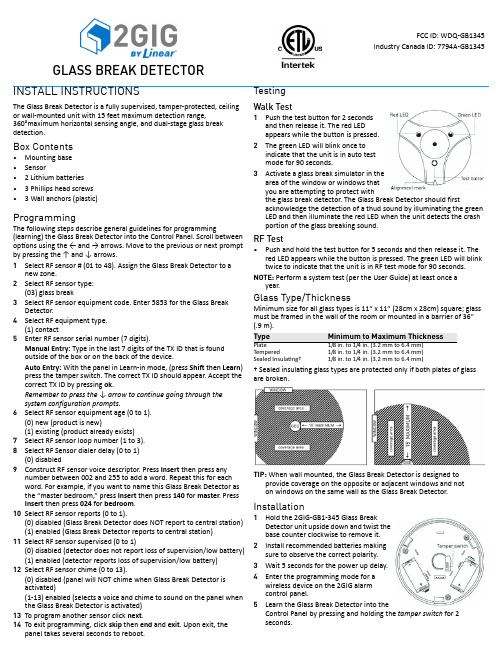
GLASS BREAK DETECTORINSTALL INSTRUCTIONSThe Glass Break Detector is a fully supervised, tamper ‐protected, ceiling or wall ‐mounted unit with 15 feet maximum detection range,360°maximum horizontal sensing angle, and dual ‐stage glass break detection.Box Contents•Mounting base •Sensor•2 Lithium batteries •3 Phillips head screws •3 Wall anchors (plastic)ProgrammingThe following steps describe general guidelines for programming(learning) the Glass Break Detector into the Control Panel. Scroll between op ons using the ← and → arrows. Move to the previous or next prompt by pressing the ↑ and ↓ arrows.1Select RF sensor # (01 to 48). Assign the Glass Break Detector to anew zone.2Select RF sensor type:(03) glass break3Select RF sensor equipment code. Enter 5853 for the Glass BreakDetector.4Select RF equipment type.(1) contact5Enter RF sensor serial number (7 digits).Manual Entry: Type in the last 7 digits of the TX ID that is found outside of the box or on the back of the device.Auto Entry: With the panel in Learn ‐in mode, (press Shift then Learn ) press the tamper switch. The correct TX ID should appear. Accept the correct TX ID by pressing ok .Remember to press the ↓ arrow to continue going through the system configuration prompts.6Select RF sensor equipment age (0 to 1).(0) new (product is new)(1) existing (product already exists)7Select RF sensor loop number (1 to 3).8Select RF Sensor dialer delay (0 to 1)(0) disabled9Construct RF sensor voice descriptor. Press Insert then press anynumber between 002 and 255 to add a word. Repeat this for each word. For example, if you want to name this Glass Break Detector as the “master bedroom,” press Insert then press 140 for master . Press Insert then press 024 for bedroom .10Select RF sensor reports (0 to 1).(0) disabled (Glass Break Detector does NOT report to central station)(1) enabled (Glass Break Detector reports to central station)11Select RF sensor supervised (0 to 1)(0) disabled (detector does not report loss of supervision/low battery)(1) enabled (detector reports loss of supervision/low battery)12Select RF sensor chime (0 to 13).(0) disabled (panel will NOT chime when Glass Break Detector is activated)(1‐13) enabled (selects a voice and chime to sound on the panel when the Glass Break Detector is activated)13To program another sensor click next .14To exit programming, click skip then end and exit . Upon exit, thepanel takes several seconds to reboot.TestingWalk Test1Push the test button for 2 seconds and then release it. The red LED appears while the button is pressed.2The green LED will blink once to indicate that the unit is in auto test mode for 90 seconds.3Activate a glass break simulator in thearea ofthewindow or windows that you are attempting to protect withthe glass break detector. The Glass Break Detector should firstacknowledge the detection of a thud sound by illuminating the green LED and then illuminate the red LED when the unit detects the crash portion of the glass breaking sound.RF Test•Push and hold the test button for 5 seconds and then release it. The red LED appears while the button is pressed. The green LED will blink twice to indicate that the unit is in RF test mode for 90 seconds.NOTE: Perform a system test (per the User Guide) at least once ayear.Glass Type/ThicknessMinimum size for all glass types is 11” x 11” (28cm x 28cm) square; glass must be framed in the wall of the room or mounted in a barrier of 36” (.9 m).† Sealed insula ng glass types are protected only if both plates of glass are broken.TIP: When wall mounted, the Glass Break Detector is designed toprovide coverage on the opposite or adjacent windows and not on windows on the same wall as the Glass Break Detector.Installation1Hold the 2GIG ‐GB1‐345 Glass Break Detector unit upside down and twist the base counter clockwise to remove it.2Install recommended batteries making sure to observe the correct polarity.3Wait 5 seconds for the power up delay.4Enter the programming mode for a wireless device on the 2GIG alarm control panel.5Learn the Glass Break Detector into theControl Panel by pressing and holding the tamper switch for 2 seconds.Type Minimum to Maximum ThicknessPlate1/8 in. to 1/4 in. (3.2 mm to 6.4 mm)Tempered1/8 in. to 1/4 in. (3.2 mm to 6.4 mm)Sealed Insula ng†1/8 in. to 1/4 in. (3.2 mm to 6.4 mm)FCC ID: WDQ ‐GB1345Industry Canada ID: 7794A ‐GB1345Mounting1Place the Glass Break Detector base on the opposite wall or adjacent wall to the window being protected.2Affix the base to the desired location utilizing the 3 long mounting screws with anchors that are supplied.TIP: For wall mounting the test button should be oriented down nearest the floor.IMPORTANT: When attaching the detector to the base, match the alignment marks and twist clockwise. If batteries are not present,the red tabs must be held away from the detector.Inserting and Replacing BatteriesIf a supervised Glass Break Detector battery is low, a low battery notification is indicated on the Control Panel’s touch screen. If indicated, replace the battery immediately. Use only the recommended replacement batteries (See Specifications).•Remove the cover by twisting counterclockwise. Use only the recommended replacement batteries (see Specifications). WARNING: Improper handling of lithium batteries may result in heat generation, explosion or fire, resulting in personal injuries.Replace only with the same or equivalent type of battery asrecommended by the manufacturer (see Specifications).Batteries must not be recharged, disassembled or disposed of in fire.Disposal of used batteries must be made in accordance with thewaste recovery and recycling regulations in your area. Keep AwayFrom Small Children. If batteries are swallowed, promptly seekmedical attention.California Only: This Perchlorate warning applies only to Manganese Dioxide Lithium cells sold or distributed ONLY in /California, U.S.A. Perchlorate Material‐special handling may apply. See / hazardouswaste/perchlorate.SpecificationsFCC and Industry Canada Regulatory InformationThis device complies with Part 15 of the FCC's Rules. Operation is subject to the following two conditions:1This device may not cause harmful interference, and2This device must accept any interference received, including interference that may cause undesired operation.This equipment has been tested and found to comply with the limits for a Class B digital device, pursuant to Part 15 of the FCC Rules. These limits are designed to provide reasonable protection against harmful interference in a residential installation. This equipment generates, uses and can radiate radio frequency energy and, if not installed and used in accordance with the instructions, may cause harmful interference to radio communications. However, there is no guarantee that interference will not occur in a particular installation. If this equipment does cause harmful interference to radio or television reception, which can be determined by turning the equipment off and on, the user is encouraged to try to correct the interference by one or more of the following measures:•Reorient or relocate the receiving antenna.•Increase the separation between the equipment and receiver.•Connect the equipment into an outlet on a circuit different from that to which the receiver is connected.•Consult the dealer or an experienced radio/TV technician for help. This product complies with FCC radiation exposure limits for an uncontrolled environment. Avoid operating this product at a distance less than 20 cm from the user.WARNING: Any changed or modifications not expressly approved by the party responsible for compliance could void the user'sauthority to operate this equipment.Limited WarrantyThis 2GIG Technologies product is warranted against defects in material and workmanship for 1 year. This warranty extends only to wholesale customers who buy direct from 2GIG Technologies or through 2GIG Technologies’ normal distribution channels. 2GIG Technologies does not warrant this product to consumers. Consumers should inquire from their selling dealer as to the nature of the dealer’s warranty, if any.There are no obligations or liabilities on the part of 2GIG Technologies for consequential damages arising out of or in connection with use or performance of this product or other indirect damages with respect to loss of property, revenue, or profit, or cost of removal, installation, or reinstallation. All implied warranties for functionality, are valid only until the warranty expires. This 2GIG Technologies Warranty is in lieu of all other warranties expressed or implied.For technical support in the USA and Canada855-2GIG-TECH (855-244-4832)For technical support outside of the USA and CanadaContact your regional distributorVisit for a list of distributors in your regionPN 77‐000004‐001 Rev F2GIG Copyright © 2013. All rights reserved.Wireless Signal Range350 ft, open air, with 2GIG Wireless Control Panel Code Outputs Alarm; Alarm Restore; Supervisory; Low Battery Transmitter Frequency345.000 MHz (crystal controlled)Transmitter Frequency Tolerance±15kHzTransmitter Bandwidth24kHzModulation Type Amplitude Shift Keying‐On/Off Keying (ASK‐OOK) Unique ID Codes Over one million different code combinations Supervisory Interval70 minutesExternal Input Sampling Current20 uAExternal Input24V AC Standard doorbell circuitSensor Dimensions (HxD) 2.75 x 1.17 x 0.63 in. (6.98 x 2.97x 1.60 cm) Weight (including battery andmagnet)1.1 oz. (31.2 g)Housing Material ABS plasticColor WhiteOperating Temperature Limits14° to 104° F (‐10° to 40° C)Relative Humidity5‐95% Non‐CondensingBattery (installed with pull tab)One Panasonic CR2032 or equivalent LithiumbatteriesIncluded Accessories Four Phillips flat‐head screws。
Ajax GlassProtect 无线玻璃破碎探测器快速引导说明书

GlassProtect is a wireless detector detecting glass break at a distance up to 9 meters. GlassProtect is connected to the Ajax security system via the protected Jeweller protocol, with an effective communication range of up to 1,000 meters without obstacles. It can operate up to 5 years from a battery and is designed for use indoors.The detector is connected to the hub and set up via the Ajax Security system mobile application. To establish connection please locate the detector and the hub within the communication range and follow the device adding procedure.WARRANTYWarranty for Ajax devices is valid for two years after the purchase date and does not apply to the supplied battery. If the device does not work correctly, you should first contact the support service—in half of the cases, technical issues can be solved remotely!The full text of the warranty is available on the website:ajax.systems/warrantyUser Agreement:ajax.systems/end-user-agreement Technical support:********************This product can be used across all EU member states.This device in compliance with the essential requirements and other relevant provisions of Directive 2014/53/EU. All essential radio test suites have been carried out.CAUTION: RISK OF EXPLOSION IF BATTERY IS REPLACED BY AN INCORRECT TYPE. DISPOSE OF USED BATTERIES ACCORDING TO THE INSTRUCTIONSIMPORTANT INFORMATIONManufacturer: Research and Production Enterprise “Ajax” LLCAddress: Sklyarenko 5, Kyiv, 04073, UkraineBy request of Ajax Systems Inc.www.ajax.systemsA wire detector with a NC type contact may be connected to the GlassProtect using an outside-mounted terminal clamp. To lead out the wire from the GlassProtect body, break out the plug.Before using the external detector connected to the terminal clamp, activate it in the GlassProtect settings.To connect the detector to a third party security central unit using the Ajax uartBridge or Ajax ocBridge Plus integration module, follow the recommendations in the user manual of the respective device.If the detector is located in a room requiring 24-hour control, activate the "Always active" mode - GlassProtect will be actuated in case of any detected glass break, even if the system is not in the arming mode.In selecting the GlassProtect installation location, please take into account the glass break detection range and presence of any objects within the room, which hinder the sound and radio signal transmission.Prior to the attachment of the detector to a surface with screws, please perform signal strength test as well as detection area test in the Ajax Security System application for at least a minute. This will demonstrate communication quality between the detector and the hub and ensures proper installation place selection.Do not install the detector:1. Outside the premises (outdoors).2. Nearby sirens and annunciators.3. In a draught and in places with a rapid air circulation (air fans).4. Nearby any metal objects and mirrors causing radio signal attenuation or screening it.5. Within any premises with the temperature and humidity beyond the range of permissible limits.GlassProtect is set up to detecting the distinctive sound of broken glass, consisting of a low-frequency hit and high-frequency tinkle of chips. The detector is not sensitive to any pops.The GlassProtect detector microphone should be positioned at the angle no more than 90 degrees relative to the window(s). Make sure that any curtains, plants, furniture or other objects do not overcover the microphone hole. If the window is covered by thick curtains, place the detector between them and the window.Blinks 2 times per second Excellent signal levelGood signal levelPoor signal level No signalLights with interruptions once every 1.5 seconds Blinks 5 times per second Lights up for a short time once every 1.5 secondsStatus indicatorSignal level MOUNTING THE DEVICE1. Fix the SmartBracket panel on the surface in two fixing points using the bundled screws or other no less reliable attachment hardware.2. Put the detector on the panel - single blink of the light indicator will confirm that the tamper has been actuated.them and the window. 1. GlassProtect.2. Battery CR123A(pre-installed).COMPLETE SETSensitive element Electret microphoneGlass break detection distanceUp to 9 mAnti-tamper switch YesRadio signalUp to 1,000 m(any obstacles absent)Socket for connecting wire detectors Yes, NCPower supply 1 battery CR123A, 3 VBattery life Up to 5 years Operatingtemperature range From 0°С to +50°СOperating humidity Up to 90%Overall dimensions Ø20 х 90 mmWeight30 gFrequency band 868.0-868.6 MHz Effective radiated power 6.01 dBm / 3,99 mW(limit 25 mW)Modulation GFSKMicrophone coverage angle180°3. Installation kit.4. Quick Start Guide.。
2GIG-GB1-345玻璃断裂传感器说明
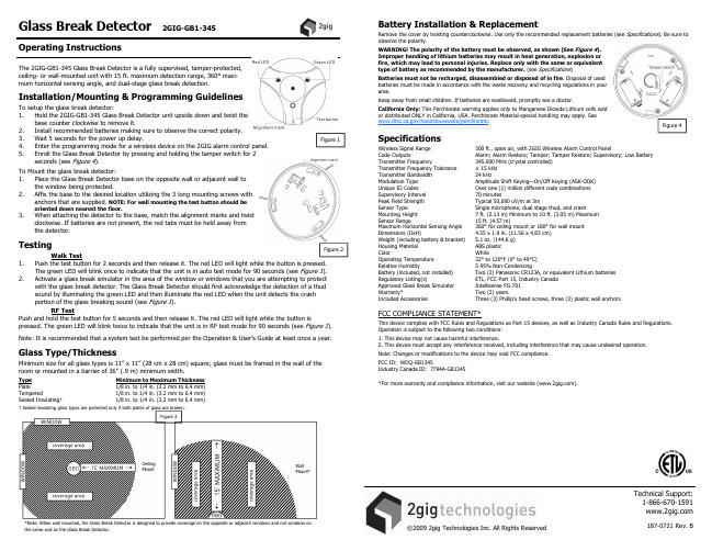
Type Plate Tempered Sealed ulating†
Minimum to Maximum Thickness 1/8 in. to 1/4 in. (3.2 mm to 6.4 mm) 1/8 in. to 1/4 in. (3.2 mm to 6.4 mm) 1/8 in. to 1/4 in. (3.2 mm to 6.4 mm)
WARNING! The polarity of the battery must be observed, as shown (See Figure 4). Improper handling of lithium batteries may result in heat generation, explosion or fire, which may lead to personal injuries. Replace only with the same or equivalent type of battery as recommended by the manufacturer. (see Specifications)
2. Activate a glass break simulator in the area of the window or windows that you are attempting to protect
with the glass break detector. The Glass Break Detector should first acknowledge the detection of a thud
Installation/Mounting & Programming Guidelines
破玻器产品使用说明书

无线遥控自动破玻器【应急破玻逃生装置】使用说明书请严格按照此说明书进行安装和使用1.产品图示2.产品概述应急破玻逃生装置俗称自动破玻器。
采用独有专利技术和最先进的工艺,无需布线。
告别传统破玻器需要依赖外接电源,布线,手动操控和故障频发难检测等问题,解决了在紧急情况下钢化玻璃无法击破,不能迅速打开逃生通道的问题。
广泛用于高层建筑、写字楼、宾馆酒店等人员密集场所及消防通道、排烟窗、公交、客运、旅游巴士、单位通勤车辆、校车、中巴等!3.产品特点1)先进的无线遥控技术,消除布线困扰。
2)司机整车按键遥控破玻,乘客单个按键破玻,落水手动+自动破玻。
3)具有独立自检,防盗防误触发声光报警。
4)先进的光合+储电,无需占用车载电源。
5)每个破玻点系统独立,可靠性高。
6)破玻力度大,作用时间短,1S 内即能击碎 5~12mm 及双层汽车钢化玻璃。
7)安装十分便捷,安装一台车(4 个破玻器)用时不到十分钟。
8)破玻系统的部件安装无螺丝裸露,不破坏整车结构,外观协调美观。
4.检测&安装1)检查安全栓检查破玻器侧边的安全栓是否安装注:无安全栓禁止后续所有操作。
2)破玻器通电测试依次打开破玻器上的防误触透明盖子,破玻器灯闪和蜂鸣报警则通电正常。
3)遥控器电量和信号检测盖回防误触透明盖,依次单按遥控器上的按钮,遥控器和破玻器对应指示灯闪烁、破玻器蜂鸣报警。
4)主体安装拆下金属卡座并用螺丝固定在合适位置的车窗梁上,装回主体。
(详情请参考安装要求)5)卸掉安全栓拔掉安全栓分别用硅胶塞将安全栓口和其他卡口塞住。
5.操控说明1)乘客控制车辆着火或落水等紧急情况下,所有人员均可掀开盖子按下手动破玻按钮,破玻器自动破玻.2)司机控制紧急情况下,司机同时按下遥控器双按钮一秒,随车装配的所有破玻器自动破玻。
3)车辆落水自动破玻车辆落水后,水浸传感器浸水启动自动破玻6.注意事项1)产品必须由本公司专业人员或者本公司培训经授权的人员实施安装。
玻璃仪器操作指引
第V0版
初版发行
2020-10-26
编 写 人:
Prepared by
审 批 人:
Approved by
如此印章并非红色,IF THE CONTROL STAMP
表此文件并非合法之版COLOR IS NOTRED,THENIT
本,并不会受到控制及IS AN UNCONTROLLEDCOPY.
操作名称:玻璃仪器操作指引
Operation
客户:/
Customer
产品名称:/
Part Name
产品编号:/
Part No.
文件编号:
Document No
版 本: 第 V0 版
Revision
日 期:202
更 改 内 容
Revision Details
生效日期
更新,请使用受控之文PLEASED REFERONLY TO
件。THE CONTROLLED COPY.
一、目的:
确定玻璃仪器的操作方法,防止任何误用导致测量误差
二、适用范围:
适用于公司化验室和测试室
三、职责:
各部门工程师对操作人员进行培训指导
四、内容:
准备:1.检查仪器是否有破损或刮花,如果有则需更换
在取样前按以上操作用被取溶液清洗移液管两次,如果溶液粘度太大,样品溶液在放出时,移液管垂直放置的时间应相应延长。
B.容器类(容量瓶、量筒)
容器先只罐80%左右的体积,并边添加边摇匀,当体积接近刻度线时,改用滴管进行滴加,并用眼睛平视容器刻度线,当凹液面与刻度线相切时就到了规定体积。
如果是量取规定浓度的溶液,容器在量之前应用该溶液清洗几次,如果是配制规定浓度的溶液,则不需要。
BP02 玻璃破碎探测器使用说明书

安装图:
过线孔
螺钉孔 (2)
螺钉孔 (3)
开盖钮(1)
2、安装范围的选择: 选定的安装位置必须能让探测器内的收声话筒毫无阻挡的直接朝向需要保护的玻璃表面上,而玻璃表面 要在最佳探测角度范围之内。可选择天花板或玻璃的旁边或对面,不要使用被测玻璃所在的那面墙,要 避免探测器感应到发出噪声的物体,如:铃、电风扇、压缩机以及机械设备等;如果环境内有潮湿物体 (如:窗帘、地毯、家具等)时,安装范围可在离被测玻璃(1~10)m 内考虑;如果环境内产生回音, 安装范围仅在离被测玻璃(1~5)m 内考虑。
接线 VCC:电源正 NO: 继电器常开 NC: 继电器常闭
GND: 电源负 C: 继电器公共端
说明:BP02 玻璃破碎探测器外壳上有两个指示灯,分别为绿色和红色。绿灯亮,表示轻微报警,无继电器 输出;红灯亮,表明已探测到玻璃破碎信号,继电器输出。
外形图
(尺寸:长×高×宽=90×65×20mm)
技术参数
● 供电电压: 12 VDC 24VDC ● 最大电流:30mA ● 使用温度:0~50℃ ● 测量范围:□ 6m □ 9m □ ● 输出形式:继电器输出: 1.5A、24VDC
安装
1、安装步骤孔穿线; 3) 连接接线端; 4) 将螺钉插入螺钉孔(2)和(3)固定探测器在指定位置; 5) 盖上上盖。
- 1、下载文档前请自行甄别文档内容的完整性,平台不提供额外的编辑、内容补充、找答案等附加服务。
- 2、"仅部分预览"的文档,不可在线预览部分如存在完整性等问题,可反馈申请退款(可完整预览的文档不适用该条件!)。
- 3、如文档侵犯您的权益,请联系客服反馈,我们会尽快为您处理(人工客服工作时间:9:00-18:30)。
接线 VCC:电源正 NO: 继电器常开 NC: 继电器常闭
GND: 电源负 C: 继电器公共端
说明:BP02 玻璃破碎探测器外壳上有两个指示灯,分别为绿色和红色。绿灯亮,表示轻微报警,无继电器 输出;红灯亮,表明已探测到玻璃破碎信号,继电器输出。
ቤተ መጻሕፍቲ ባይዱ
BP02 玻璃破碎探测器使用说明书
ColliHigh 昆仑工控
产品简介
BP02 玻璃破碎探测器根据玻璃破碎时会产生特有的音频信号的原理,在玻璃破碎时产生报警,防止非 法入侵。能测试的玻璃种类包括钢化玻璃、强化玻璃、层化玻璃等。它有灵敏度高、响应时间快、无误报、 使用方便、便于安装的优点;适用于宾馆、商店、图书馆、珠宝店、仓库以及其他对玻璃破碎需要报警的场 所。
安装图:
过线孔
螺钉孔 (2)
螺钉孔 (3)
开盖钮(1)
2、安装范围的选择: 选定的安装位置必须能让探测器内的收声话筒毫无阻挡的直接朝向需要保护的玻璃表面上,而玻璃表面 要在最佳探测角度范围之内。可选择天花板或玻璃的旁边或对面,不要使用被测玻璃所在的那面墙,要 避免探测器感应到发出噪声的物体,如:铃、电风扇、压缩机以及机械设备等;如果环境内有潮湿物体 (如:窗帘、地毯、家具等)时,安装范围可在离被测玻璃(1~10)m 内考虑;如果环境内产生回音, 安装范围仅在离被测玻璃(1~5)m 内考虑。
外形图
(尺寸:长×高×宽=90×65×20mm)
技术参数
● 供电电压: 12 VDC 24VDC ● 最大电流:30mA ● 使用温度:0~50℃ ● 测量范围:□ 6m □ 9m □ ● 输出形式:继电器输出: 1.5A、24VDC
安装
1、安装步骤: 1) 按下探测器上边沿的开盖钮(1),移开上盖; 2) 通过外壳背面的一个孔穿线; 3) 连接接线端; 4) 将螺钉插入螺钉孔(2)和(3)固定探测器在指定位置; 5) 盖上上盖。