三星贴片机系列参数
三星贴片机SM321系列程序编写步骤
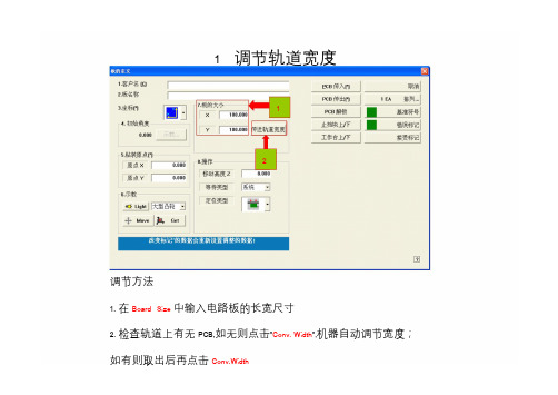
1 调节轨道宽度12调节方法1. 在Board Size 中输入电路板的长宽尺寸2. 检查轨道上有无PCB,如无则点击"Conv. Width",机器自动调节宽度;如有则取出后再点击Conv.Width2 PCB原点设置---步骤1设置方法:1. 按动AXIS键,使X Y轴灯亮2. 按动MODE键,使JOG 或BANG灯亮方向键3. 选择一个焊盘的直角位置,按下方向键使显示屏的十字架的交点指示在该直角的位置,(如下图的R127右下角)xy轴灯R127PCB原点设置---步骤24. 将光标移动到origin x或origin y5. Device 选择FID. CAM46. 点击Get563 拼板设置---步骤1设置方法:1. 点击Array[排列]1.设置拼板排列[ARRAY]拼板设置---步骤22. 输入拼板数量(如5*1)x y3. 点击Apply[应用]3拼板设置---步骤34. 按动AXIS键,使X Y灯亮5. 按动MODE键,使JOG 或BANG灯亮6. 按下方向键使显示屏的十字架的交点指示在第二块PCB的R127的位置,如下图方向键工作模式第二块PCBR127xy轴灯拼板设置---步骤47 810 127. 点击将光标选择到Array[数组]的No.2位置98. Device选择FID.CAM拾取坐标的方法9. 点击Get10.在R中输入角度11. 重复6-10的步骤做出Array 的No.3,4,5的位置12.点击OK[确定]4 基准点设置---步骤1设置方法:1. 点击Fiducial Mark [基准符号]1基准点设置---步骤22. 在Position Type [位置类型]选择基准点类2型基准点设置---步骤33. 按动AXIS键,使X Y灯亮4. 按动MODE键,使JOG 或BANG灯亮5. 按下方向键使显示屏的十字架的交点指示在第一个基准点的中心位置,如下图方向键xy轴灯基准点设置---步骤46. 光标点到Mark 6 7P osition 的No.1的X 或Y 位置 7. Device 选择Move 9Camera 一一对应 8. 点击Get9. 在Mark ID 里输入ID 号(如"1")10. 在Mark List 点击No.1,使光标显示在该位置基准点设置---步骤511. 选择基准点的中心颜色12. 调节相机亮度,使中心的颜色与周围的颜色区分清晰,如下图基准点的中心颜色在此选择调节相机亮度White :中心比周围白Black :中心比周围黑基准点设置---步骤613. 点击Tuning1714.在Vision Status 中点"ok"15. 重复3-14的步骤做出第二个基准点的数据16. 点击Scan后选择确定1617. 点击"ok"保存数据退出13绿色状态时点OK5元器件的建立---步骤1设置方法:1. 在PCB Edit 点击F3 Part[元件]元器件的建立---步骤22. 点击New Part 2元器件的建立---步骤3353. 输入元件规格名称44. 选择封装65. 测量元件厚度并输入6. 点击Common Data元器件的建立---步骤497. 选择Feeder 类型7 8.选择Nozzle 类型9. 点击Register[注册]8调用已编好的元器件设置方法:1. 在Part Group& Part List 里选择封装2. 选择一个需要的元件名并连续点击两次鼠标左键3. 在随后出现的New PART Name里点击"OK"元器件参数编辑---步骤1设置方法:1. 在"PCB编辑"菜单下点击"F3 元件"2. 选中目标元件名光标在此3. 点击"EDIT [编辑]" 元件参数编辑按钮元器件参数编辑---步骤24. 点击"MOVE [移动]"5. 在随后出现的"校正测试--移动"对话框中选择"DEVICE [装置]"点此选择吸头号6. 点击"PREPAREMANUAL PICK [准备手动吸取]"准备手动吸取元器件参数编辑---步骤37. 此时吸嘴会降下来,手动将10 元件安装到该吸嘴上8. 点击"准备校正测试"9. 在随后出现的"问题"对话框点"是" ,如下图.此时吸嘴移动到相机的中心点位置进行元件的照相识别10. 点击"关闭"89元器件参数编辑---步骤411. 点击"亮度控制"及"门槛"13设置相机的照明环境,要求元件二元图象的金属引脚与塑料本体黑白清楚,周围无白色二元图象或黑色杂点1212. 点击"TEXT [测试]"或"AUTO TEACH [自动示教]",在随后出现的对话框显示绿色的表示参数与实际的元件设置照明环境符合13. 点击"COMMON DATA [公共数据]"实际图像显示二元图像显示元器件参数编辑---步骤51614. 选择"FEEDER[喂料器]"设置元器件的包装形选择元器件的包装形式式15. 选择合适的吸嘴类型1516. 点击"OK[确定]"17. 重复1--16的步骤设置其他元器件的参数Stick Feeder 的设置---步骤1设置方法:1. 点击F4 [Feeder]2. 点击Stick Unit3. 选择Feeder TYPE 1为BELT MULTI STICK32Stick Feeder 的设置---步骤24. 点击Change5 75. 在Feeder Base 中输入1或2Feeder Base6点击4 后出现1:前面FEEDER BASE2:后面FEEDER BASE6. 在Slot No中输入放置的站号47. 点击"OK"Stick Feeder 的设置---步骤38. 选择元件规格名称8Stick Feeder 的设置---步骤410. 按动AXIS键,使X Y灯亮11. 按动MODE键,使JOG 或BANG灯亮12. 按下方向键使显示屏的十字架的交点指示在元件的中心位置,如下图方向键xy轴灯Stick Feeder 的设置---步骤513. Device 选择FIDCAM14. 光标点到元件名称的位置14.当前有效位置16.元件检测角度15. 点击Get13.选择相机类型16. 在Part R里选择元件的检测角度15Tray Feeder 的设置---步骤1设置方法:1. 点击Tray Unit232. 在Part 里选择元件规格3. 输入盘子的元件数量XN:X方向的元件数量YN:Y方向的元件数量1Tray Feeder 的设置---步骤24. 按动AXIS键,使X Y灯亮5. 按动MODE键,使JOG 或BANG灯亮6. 按下方向键使显示屏的十字架的交点指示在1st-1的位置方向键3rd-1 3rd-21st-2xy轴灯1st-12nd-22nd-1Tray Feeder 的设置---步骤37. Device选择FIDCAM118. 光标点到1st-1的X或Y9. 点击Get 得到坐标810. 输入PART R检测角度711. 重复6-10 步骤得出1st-2,2nd-1, 2nd-23rd-1, 3rd-2的坐标及PART R 9Step的编辑---步骤1设置方法:1 2 31. 点击F5 Step2. 在Reference 里输入元件代号3. 在Part里选择对应的元件规格4.重复2-3的步骤,把所有需要贴片的元件代号输入Reference里,并选择对应的元件规格Step的编辑---步骤25. 按动AXIS键,使X Y灯亮6. 按动MODE键,使JOG 或BANG灯亮7. 按下方向键使显示屏的十字架的交点指示在第一块电路板的R12焊盘的中心位置,如方向键下图xy轴灯Step的编辑---步骤39118. Device选择FID CAM9. 光标点到R1的元件代号位置10. 点击Get11. 设置元件的贴装角度R812. 重复7-11的10步骤找出所有元件代号的坐标Optimize的使用---步骤1设置方法:1. 点击F8 Opti2. 在随后出现的"保存为"对话框中输入文件名13.点击"保存"2 3Optimize的使用---步骤284. 点击RemoveTape575. 输入安装的喂料器数量6. 选择目标元件6 7. 点击Set8. 点击Nozzle 4Optimize的使用---步骤39. 将需要用到的吸嘴型号从Prohibited 移动到Available10. 从Arranged 删除不需要用到的吸嘴移动按钮需要用到的吸嘴型号Optimize的使用---步骤41111. 点击Parameter12. 拼板类型把Extend12前的小框打勾,非拼板类型不需要13. 点击RunOptimizer13Optimize的使用---步骤514. 点击Accept14。
SMT工艺设计规范
2.4 PCB焊盘设计 焊盘设计总的规则是元件的焊盘投影必须落在PCB焊盘之内,且周围留有一定的剩余 面积以利形成带弧度的焊接表面,焊盘设计应对称,双端元件两个焊盘尺寸一致。
各类型元件的焊盘具体尺寸见图表1及图示。
W L D
1)焊盘长度L=元件焊盘长度+元件焊盘高度+0.25 (mm) 2)焊盘宽度W=元件宽度+0.25 (mm) 3)焊盘间距D=元件焊盘间距-0.25(mm) 4)具体尺寸见表1 表1 普通片状元件的焊盘设计尺寸备查表
5mm 宽的工艺边 贴片完成后去除
2.3 PCB拼板设计 2.3.1对于尺寸小于50×50mm的PCB,可以设计成拼板,如图所示。但拼板后的总尺寸又 不能超出L510×W460mm的范围(包括附加的工艺边),各小拼板的方向尽量保持一致,并维 持长边在PCB的流向方向,丝印文字正对人眼。各拼板之间采用V-CUT半切口连接,如图7所 示。即两面各切入1/3的深度,中间保留1/3的板厚,可用手工很方便的分离。 在电路设计中 可直接将PCB实体拷贝拼接在一起,板间留0.3mm的余量用于切口,但注意应将完全靠边的 铜箔线路从板边往内收缩至少0.75mm,避免PCB切口加工时刀具伤及铜箔线路。采用V-CUT 拼板的PCB厚度一般不超过3.5mm。 2.3.2从设备的综合利用率和生产效率出发,我们公司自动贴片机基本按1+1配置,为最大限 度的提高设备单位产能,这样对我们前期拼板及拼板后元件有一个基本的规定,当拼板后元 件点数不少于420点,这样就达到SMT设备生产效率最大化。
焊盘从引脚弯折处开始,到元件脚边缘结束,四周再向外延伸0.3mm。 晶体管焊盘设计
焊盘从元件脚弯折处开始,到元件脚边沿结束,四周再向外延伸0.3mm。
普通集成电路芯片焊盘设计
三星471-482贴片机培训

PCB板的原点坐标、 板子的长宽; 2、手动控制板子的进 出,止挡块、工作 台的上/下控制; 3、基板标记、不良板 标记。
2021/10/10
3
2、子菜单:元件(F3)
菜单的功能: 1、在资料库中选择
元件的种类和规 格; 2、资料库中没有的 元件可以在该菜 单新建。
2021/10/10
32
4、子菜单:照相机
菜单功能: 1、设定有关摄像 机的各种数据, 执行摄像机的校 准(校正)功能。
2021/10/10
33
5、子菜单:外围设备
菜单功能: 1、对Dump Box 和Tray Feeder进 行设定。
2021/10/10
34
6、子菜单:亮度
菜单功能: 1、检测和校准所 有相机 的亮度。
2021/10/10
4
3、子菜单:供料器(F4)
菜单功能: 1、可以编辑/和查看
每一站供料器的 用料种类和规格; 2、可以矫正飞达、 振动飞达、Tray 盘的取料位置。
2021/10/10
5
4、子菜单:步骤(F5)
菜单功能: 1、查看/编辑元件的
贴装位置、种类、 规格、贴装角度、 贴装步骤、使用 吸嘴; 2、矫正元件的贴装 位置。
三星贴片机培训资料
2021/10/10
SM471/482
1
一、PCB编辑界面的认识
主菜单介绍: 1、 PCB编辑里面有
9 个子菜单:板 子F2、元件F3、 供料器F4、步骤 F5、ANC构成F6、 周期F7、优化F8、 取消F10、基板 直观图F11.
2021/10/10
2
1、子菜单:板子(F2)
22
三星贴片机技术全参数

三星贴⽚机技术全参数三星SM贴⽚机技术说明第⼀:三星贴⽚机SM4111、产品图⽚:2、产品介绍:SM411采⽤实现中速机的最快速贴装的三星专利On The Fly识别⽅式,以及双悬臂结构,从⽽达到芯⽚元器件42,000 CPH、SOP元器件30,000 CPH(IPC9850标准)在同类产品中拥有世界最快速的贴⽚速度。
并且,其在⾼速中也能实⾏50微⽶的⾼精度贴⽚,从⽽从最⼩0402芯⽚到最⼤□14mmIC元器件为⽌,皆可以实⾏贴⽚.产品基本特性:对中⽅式飞⾏视觉轴的数量6轴*2台架贴装速度飞⾏视觉Chip 1608 42,000 CPH(IPC9850) SOP 30,000CPH(IPC9850)贴装精度Chip±50um@3ó/Chip(使⽤标准元器件样品)窄间距贴装0.1mm(0603)/0.15mm(1005)元器件范围范围0603~□14mm Chip,QFP,BGA(0402选件) 最⼩引脚间距(QFP)最⼩球间距(BGA) 0.5mm(QFP)/0.65mm(BGA)最⼤⾼度H=12mmBoard尺⼨(mm) 最⼩50(L)*40(W)最⼤510(L)*460(W)(单导轨模式)510(L)*250(W)(双导轨模式)610(L)*460(W)(选件)PCB厚度0.38-4.2供料器数量120ea/112ea(供料器交换车)能耗耗电量AC200/208/220/240/380/415V(50/60Hz,3Phase) MAX.5.0kVA耗⽓量5~7kg/m2 300Ne/min重量1,820kg外形尺⼨(mm) 1,650(L)*1,690(D)*1,535(H)3、优点:平⾏双轨, 搬运PCB时间0秒极低的物料损耗率:万分之⼆三星独有的飞⾏对中识别系统(Fly Vision)供料器元件位置⾃动识别功能先进的扁平线结构防静电ESD吸嘴新型不停机送料器PM Manager管理功能第⼆、三星贴⽚机SM4211、产品图⽚:2、产品介绍:SM421采⽤实现中速机的最快速贴装的三星专利On The Fly识别也能对应从0603微⼩芯⽚到22mm IC元器件。
三星SM系列贴片机编程培训
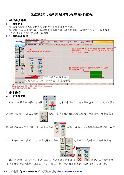
1.操作安全事项1.1 操作安全※ 使用机器前请先阅读机器附带操作手册的安全事项部分.※ 拆装 Feeder (喂料器) 或操作者身体任何部位进入机器前,必須打开安全门,或者按下 “EMERGENCY ”键,然后才可以操作!1.2 机器画面认识2.基本操作2.1 开关机步骤开机,选择左侧的操作者按键选择“管理者”,输入原始密码“1”,进入机器状态栏的“应用”,点击左侧的 按钮,在弹出的画面设定暖机时间,开始暖机。
暖机完成后,选择所需要的生产用文件,点击画面左侧的 按钮,在弹出的画面选择需要的程序,再回到主状态栏下的“生产” ,依次选择左上侧的完成-PCB 下载-开始,点击面板上的“START ”按键,开始生产,生产完成后,点击主画面左下方的 按键,保存当前文件,在弹出的对话框中选择“退出窗口”,工控机关机,待画面变黑色后,关闭电源,安全关机。
SAMSUNG SM系列贴片机程序制作教程2.2 设备回原点※ 开机进入设备操作主画面后,点击左下角的按钮,等待设备回原点后,方可进行下一步操作!※ 回原点前确认吸嘴及轨道在正常状态。
3.程序编制3.1 基板的定义1.点击主画面左侧的“基板”按钮,进入“基板定义”画面。
2.依次输入“客户名”和“板名称”,客户名的输入是为了下次方便寻找,板名称必须输入。
3.一般情况下此框内的选项不需要更改。
4.根据板的实际长宽分别输入X Y 对应的框内,并在确认轨道内无异物的情况下,调整轨道宽度。
5.此框内的各个选项无需更改,6.移动高度指设置PCB 板的顶面以"0"为基准头部移动的高度,保持默认即可。
定位类型有以下几种:7.将准备好的PCB 板放在设备轨道进口的感应器上方,点击“PCB 传入”23456878. 点击“基准标记”按钮,出现以下画面:1324563.2 元件的定义1. 点击主画面左侧“元件”按钮,出现以下画面:2. 点击上图中的“新建元件”按钮,出现下图需要设置元件信息的画面3.将元件信息设置完成后,点击上图右上角的“公共数据”按钮,进一步设置元件相关属性,如下图:在此处输入所要新建的元件名选择所要新建的元件的封装形式,电阻选择:chip-R****,电容选择:chip-C****,三极管选择:TR/TR2(根据送料方式不同选择),IC 只有两边有引脚的选择:SOP/SOP2,IC 四边有脚的选择:QFP 。
三星贴片机操作中文说明1
第一章設備大体結構介紹及操作利用1-1 機台外觀及各部專業名稱介紹1-2開關機程序1-2-1 開機步驟 0–1 檢查輸入電壓是不是為單相220伏特交流電。
步驟 0-2 檢查面對機台右下方的開關是不是在”ON”的位置。
步驟 0-3 檢查位在前方及後方的急緊開關(Emergency Stop)是不是為解除。
步驟 1 將<Isolation Switch>順時針方向打開。
打開<Isolation Switch>後,直接按下Start,以避免傷及硬體。
步驟 3 進入主程式後,按下位在Operation Panel上的<Ready Switch>。
步驟 4 拿起Teaching Box,設定Mode = Home之後,按下<Home Start>( ▼向下的方鍵),此時,機台所有的軸(Axis X,Y,Z,R)會做歸原點的動作。
步驟 5 暖機三到五分鐘。
選擇Mount→Warm-Up,按下選擇”START”。
1-2-1 關機步驟 1 選擇File→Exit(或按下Alt + F4),就會離開Windows作業系統。
步驟 2 按下位在<Isolation Switch>的Stop(紅色按鈕),即能够移除馬達電源。
步驟 3 待電腦所有的程式皆關閉結束後,將<Isolation Switch>逆時針關閉即可。
1-3 操作面板各種功能的說明及利用1-3-1 操作面板上的按鈕功能說明及利用1.<Isolation> switch其功能為提供或停止設備的主電源,以轉動開關來提供電源,電源指示燈會亮,且在一會兒,工作畫面會出現在”Programming Monitor”。
在關機期間,供應Driver的電源是關閉的,例如馬達。
只有在結束MMI主程式才需要關閉電源,若是突然關閉電源,資料及主機可能會受損,且在下次開機時,設備可能會發生故障。
2.<Main start> switch要供應電源至電力系統,例如馬達,按下<main start>switch的綠色按鈕來提供電源。
三星贴片机SM421技术规格
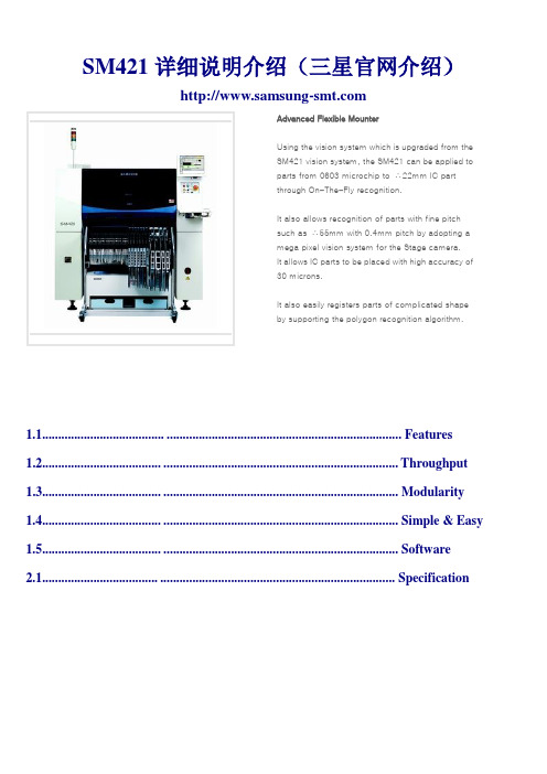
SM421详细说明介绍(三星官网介绍)Advanced Flexible MounterUsing the vision system which is upgraded from theSM421 vision system, the SM421 can be applied toparts from 0603 microchip to ∴22mm IC partthrough On-The-Fly recognition.It also allows recognition of parts with fine pitchsuch as ∴55mm with 0.4mm pitch by adopting amega pixel vision system for the Stage camera.It allows IC parts to be placed with high accuracy of30 microns.It also easily registers parts of complicated shapeby supporting the polygon recognition algorithm.1.1............................................................................................................... Features1.2..............................................................................................................Throughput 1.3.............................................................................................................. Modularity 1.4.............................................................................................................. Simple & Easy1.5.............................................................................................................. Software2.1............................................................................................................. Specification➢Features➢ThroughputThe unique On-The-Fly image recognition technology of Samsung Techwinown that allows part recognition without stopping after part pickup, minimizingthe time of movement between pickup position and placement position andmaximizing the placement speed by zeroing the recognition time.• Placement Speed:42,000 CPH (IPC9850),51,000 CPH (Optimal Condition)By adopting a dual work conveyor and shuttle inlet conveyor of first-in-firstout type, the PCB feeding type wasminimized and gantry efficiency is maximized due to elimination of a common work area, thus maximizing theactual productivity. Each gantry can work at full speed independently without risk of interrupting the opposinggantry. In addition, it supports various placement modes according to production characteristics and board size.The twin servo system applied to each axis of the gantry structure allows high speed placement bystrong accelerating force.• Equipped with self motion controller• Reinforced rigidity of driving system• Implementation of high acceleration and low vibration• Reduced setting time• Reinforced absolute accuracy and repetition accuracyChip ±50㎛(Cpk≥1.0),IC±30㎛(Cpk≥1.0)The newly upgraded placement accuracy calibration system automatically checks and calibrates the pickup point offset, head offset, C/V offset, etc. to allow reliable part placement.•Absolute Accuracy : ±50㎛(Cpk≥1)➢ModularityIt has an enhanced part registration library to allow quick part registration as well as stable part recognition and placement, and supports the polygon recognition related to unregistered part to allow the parts of complicated shape to be registered easily.The mega pixel camera allows the placement of parts from 0603(01005) micro chips. The SM400 series machine also allows recognition of larger parts with fine pitch or balls using 45mm camera such as □42mm with 0.4mm pitch by adopting a me ga pixel vision system for the Stage camera.The SM Series dual-lane conveyor system accommodates PCBs up to 250mm, increasing the overall placement speed. The system can also accommodate PCBs up to 460mm on a single-lane conveyor.The highest productivity compared to the area of machine : 11,700 CPH/m2➢Simple & EasyThe height of the machine was lowered through ergonomic redesign and the operation panel and keyboard position were optimized for convenient operationTwo operating consoles allow access to system controls from both the front and rear sides of themachine.All utility connections are installed inside the machine to provide aclean and safe environment.For the grease injection that is periodically performed during maintenance, the position of the nipple was considered for convenient grease injection.Samsung’s optional IT Feeder System assures correct feeder positioning because it checks the replaced feeder locations every time a component is loaded. The machine does not enter production mode when feeders are loaded incorrectly. It alerts the operator and provides easyto- follow instructions for corrective action.IT Feeder FeaturesBuilt-in CPU Board / Use of Device Net / Maintenance Record / Storage of Component No., Component Inventory, etc. / Component Shortage Warning LED / Feeder Recognition / ConfirmationFeeder Placement VerificationPerforms a changeover setup verification each time a feeder is reinserted. This feature saves valuable time and avoids costly rework due to incorrect feeder positioning.Remaining Component Quantity AlarmHelps to ensure continuous system operations. This basic function of the IT Feeder System alerts the operator that a component supply needs to be replenished, based on the remaining quantity.Production Information Tracking / Recording FunctionAutomatically tracks and generates a record of production information, such as operation hours, program developer, operated equipment, worked on components, etc.A machine checking software that automatically warns the time required for maintenance of the machine.Creates automatic placement routines on any number of machines in a production line, to configure the most productiveline balance for any environment or series of products.The SM Series features built-in optimizer software to ensure exceptionally efficient machine operation. Itautomatically configures the optimum feeder set-up and most efficient program sequence according touser-defined priority conditions. This function minimizes changeover while maximizing machine runtime.Top-quality accessories, such as non-stop tape feeders and non-stop tray feeders, increase overall system reliability and help significantly reduce amount of machine downtime.Non-Stop Tape FeederThe new SM tape feeder employs an endless-discharge method of nonstop operation in delivering reliable,repeatable, and efficient component pickups. Components supplied on tape can be reloaded easily while themachine is running, ensuring smooth continuous system operation(SM Tape Feeder).Non-Stop Tray FeederJEDEC tray cassettes are separated into upper and lower portions and can operate independently. Traycomponents also can be reloaded while the machine is running, enabling consistent non-stop operation.Side Tray FeederEntire JEDEC trays can be presented to the machine without any impact on PCB process width or availablefeeder slot locations, allowing for direct pick-up from tray and maximum efficiency of feeder space.Non-Stop Tape SplicingProvide a continuous, steady supply of available components quickly and easily using a component tape connecting splicer.Automatic Pickup Position AdjustmentSM Series systems perform real-time recognition of a component as it is picked up from the component feeder.This feature provides the ability to automatically adjust the pickup position, ensuring that components are pickedup consistently at the center, regardless of tape variations.Improved Accuracy• High feeder base stability• New mounting mechanism• Two position-control pins at the front side• Newly designed sprocketStable Indexing• Built-in cylinder• Optimized pressure control within the cylinder• Increased pick-up speeds with the index sensor• Tape guide automatically compensates for changes in tape thickness• Variable tape support (for feeders accommodating tape widths of 12mm and higher) Easy to Use• Swing-type reel hanger (splicing/verification)• Easy feeder identification by applying a different color for eachclamp (01005, 0201, 2p, 4p, 4E, general feeder)• Ergonomic handle design• Manual index switch (IT option)• Power supply indication lamp illuminates when fixed by the clamp• Tape guide lift prevention through the use of the control pinSamsung’s Docking Feeder Cart System is the key to rapid changeo ver. A Docking Feeder Cart can be loaded offline, and then quickly rolled up to the machine where it is pneumatically clamped to the feeder base. Both the front and rear sides of the SM Series machines are designed to accommodate the Docking Feeder Cart System.• Significantly reduce changeover time• Replace carts without halting production• Accommodates up to 56 8mm feeders per cart• Automatically connects to feeder power and air supply• Easily set the cart height using adjustable feetRegister up to 120 8mm feeders on one machine simultaneously. Concurrent optimizer support for 1 to 5programs allows for multiple models to be arranged at the same time. The sliding-type feeder systempermits the user to remove and replace feeders during operation without interrupting the overall system.The SM series can automatically generate a Job Change Order Sheet (feeder changeover report) while running productionin order to minimize setup time. This report identifies only the feeders that need to be changed, eliminating the need tocompletely reload the machine.The board transport system automatically adjusts to the precise board width in order to furtherfacilitate quick changeover.SM Series systems use nozzles that are common to other Samsung SMT assembly systems, allowing for interchangeability and optimal line balancing. With the increase in popularity of more delicate micro components, SM series systems have incorporated features to handle the demands of such products, specifically using nozzles with compliant mechanisms in order to prevent component damage.• Ceramic Nozzle • Bare Component Soft PAD Nozzle (Optional)Feeder Types/Sizes Feeder Pitch(mm)8mm (1005/0603) 8mm12mm16mm24mm32mm44mm56mm72mm88mm 244, 8, 124, 8, 128, 12, 16, 208, 12, 16, 20, 24, 32 8, 12, 16, 20, 24, 32, 40 8, 12, 16, 20, 24, 32, 40 8, 12, 16, 20, 24, 32, 40 8, 12, 16, 20, 24, 32, 40• Adjustable frequency control• 24 VDC, 0.8A 0.8• Maximum of four lanes• Applicable components - SOP, SOJ, QFP, PLCC, connector, etc.• Dual level magazine racks allow the component trays to be loaded while the machine is runni ng • Large capacity tray feeder for various odd-shaped components• 20 Tray (1 Tray / 1 Pallet)• 40 Tray (2 Tray / 1 Pallet)•One-touch mounting allows the tray to be easily inserted and removed from feeder base.• Flat tray installation surface enables high speed pickup.• M ultiple orientations, based on tray dimensions• Applicable Trays : 2", 4", 136 x 316mm, 200 x 316mm, 272 x 316mm• Type : Single-layer tray feeders (136 x 316mm) with 2 traysSingle-layer tray feeders (136 x 316mm) with 4 traysSignificantly reduce changeover time using the SM Series Docking Feeder Cart System. The system allows for replacing a complete feeder configuration in just minutes.Basic Set Configuration• Docking Feeder Base• Docking Cart• Minimize the space required to store unused or staged SMfeeders• SM feeder storage rack with 100 slots provides storage capacity for up to 100 SMfeeders (based on 8mm feeder)• SM feeder storage rack with 20 slots and the Feeder E xchange JIG providesstorage capacity for up to 20 SMfeeders (based on 8mm feeder)• Allows the user to replace tape reels in front of the machine, thus preventingfeeder damage and improving work efficiencyProvide a continuous, steady supply of available components to increase productivity and reduce machine downtime.• Manual Tape Splicing Tool• Portable Tape Splicing Tool• Performs the tape connecting function that guarantees high quality by moving the tool in front of the machine.Verify and adjust the feeder tape pocket position with the SM Series Feeder Calibration JIG as part of a scheduled system maintenance program to ensure reliable component pickups.Use the tape cutter to automatically cut used paper and plastic tape.• Non-Docking • Docking Cart➢SoftwareTo prevent inaccurate component placements, the SM Series systems verify that the expected component feedersare indeed in the required locations. The verification is performed using barcode information that is obtained fromthe feeder and component when they are installed on the system. The operator is notified of any incorrectlymounted feeder or component before production begins.• Stops operation after an error occurs if incorrect placement happens.• Al erts the operator when corrective action is required.Monitor real-time component inventory with barcode labels attached to the supply reels. Stock levels can bemonitored once the reel is assigned to a SM IT Feeder. Monitoring component consumption using the commondatabase allows the operator to replenish the system before the stock becomes depleted.Automatic RecognitionEach feeder has a unique identifier (ID) used to provide information about the feeder and component. Simply pressing a button automatically causes the feeder information to be registered with the control system.Advanced SM Series IT Feeder FunctionsEach SM IT feeder has a built-in CPU and memory that are used to store component information and maintenance history. Multicolor LEDs indicators provide the feeder status for easy identification of the feeder condition, allowing operators to easily monitor production progress at a glance.Shared DatabaseA common database stores information concerning the feeders, components, machines, and information on each job in real-time.The component shortage warning feature prevent component shortages in real-time during machine operation. Thisfeature minimizes machine downtime by permitting the operator to replenish components in advance so as to notimpact production.• Monitor remaining quantity for each component tape reel• Alert the user that a component shortage is imminentLoad components onto the SM IT feeders using offline stations that are connected to the shared database. Assign components to specific feeders to reduce changeover time, and further ensure accuracy using the built-in barcode system.• Minimize setup time using the Docking Feeder Cart• Verify feeder and component setup prior to operation using OLP changeover reportsLot Tracking, which is one of the options of IT Feeder System, traces and manages the history of the parts that wereused when producing boards. It minimizes the range of recall by using the LOT Tracking history file if an externalerror occurs, and it helps to easily cope with an error that occurs while the machine is running. Lot Tracking dataalso can be integrated with the modules of TUIC Co., to manage the history in SMD IN-LINE.The CAD data, ASCII data, and the placement information on the program of the machine made by other companies can be changed accurately and easily and they can be verified using Gerber file. In addition, the work program can be easily changed in the line by readjusting the actual line balance results of existing job files. Furthermore, it is possible to check the improvement result.It is possible to manage one integrated DB for each line through the network and perform work program management by line. Using the EasyOLP exclusively used for the line, the work program can be downloaded to each machine and the data and job files can be managed by automatically uploading the modified work program information, allowing reduction of work preparation time and easy work change.It is possible to monitor various production indexes and work status as well as detail information of themachine and improve the operation rate and the defect rate of the line by providing the function that tracks anerror when it occurs.It is possible to perform management of each user through registration of each line, equipment and users, and provide support to achieve quick production by outputting various reports. In addition, it is possible to create a program to allow multi-board and multi-work and predict actual working hours.➢Specification。
三星贴片机SM421技术规格
SM421详细说明介绍(三星官网介绍)Advanced Flexible MounterUsing the vision system which is upgraded from theSM421 vision system, the SM421 can be applied toparts from 0603 microchip to ∴22mm IC partthrough On-The-Fly recognition.It also allows recognition of parts with fine pitchsuch as ∴55mm with 0.4mm pitch by adopting amega pixel vision system for the Stage camera.It allows IC parts to be placed with high accuracy of30 microns.It also easily registers parts of complicated shapeby supporting the polygon recognition algorithm.1.1............................................................................................................... Features1.2..............................................................................................................Throughput 1.3.............................................................................................................. Modularity 1.4.............................................................................................................. Simple & Easy1.5.............................................................................................................. Software2.1............................................................................................................. Specification➢Features➢ThroughputThe unique On-The-Fly image recognition technology of Samsung Techwinown that allows part recognition without stopping after part pickup, minimizingthe time of movement between pickup position and placement position andmaximizing the placement speed by zeroing the recognition time.• Placement Speed:42,000 CPH (IPC9850),51,000 CPH (Optimal Condition)By adopting a dual work conveyor and shuttle inlet conveyor of first-in-firstout type, the PCB feeding type wasminimized and gantry efficiency is maximized due to elimination of a common work area, thus maximizing theactual productivity. Each gantry can work at full speed independently without risk of interrupting the opposinggantry. In addition, it supports various placement modes according to production characteristics and board size.The twin servo system applied to each axis of the gantry structure allows high speed placement bystrong accelerating force.• Equipped with self motion controller• Reinforced rigidity of driving system• Implementation of high acceleration and low vibration• Reduced setting time• Reinforced absolute accuracy and repetition accuracyChip ±50㎛(Cpk≥1.0),IC±30㎛(Cpk≥1.0)The newly upgraded placement accuracy calibration system automatically checks and calibrates the pickup point offset, head offset, C/V offset, etc. to allow reliable part placement.•Absolute Accuracy : ±50㎛(Cpk≥1)➢ModularityIt has an enhanced part registration library to allow quick part registration as well as stable part recognition and placement, and supports the polygon recognition related to unregistered part to allow the parts of complicated shape to be registered easily.The mega pixel camera allows the placement of parts from 0603(01005) micro chips. The SM400 series machine also allows recognition of larger parts with fine pitch or balls using 45mm camera such as □42mm with 0.4mm pitch by adopting a me ga pixel vision system for the Stage camera.The SM Series dual-lane conveyor system accommodates PCBs up to 250mm, increasing the overall placement speed. The system can also accommodate PCBs up to 460mm on a single-lane conveyor.The highest productivity compared to the area of machine : 11,700 CPH/m2➢Simple & EasyThe height of the machine was lowered through ergonomic redesign and the operation panel and keyboard position were optimized for convenient operationTwo operating consoles allow access to system controls from both the front and rear sides of themachine.All utility connections are installed inside the machine to provide aclean and safe environment.For the grease injection that is periodically performed during maintenance, the position of the nipple was considered for convenient grease injection.Samsung’s optional IT Feeder System assures correct feeder positioning because it checks the replaced feeder locations every time a component is loaded. The machine does not enter production mode when feeders are loaded incorrectly. It alerts the operator and provides easyto- follow instructions for corrective action.IT Feeder FeaturesBuilt-in CPU Board / Use of Device Net / Maintenance Record / Storage of Component No., Component Inventory, etc. / Component Shortage Warning LED / Feeder Recognition / ConfirmationFeeder Placement VerificationPerforms a changeover setup verification each time a feeder is reinserted. This feature saves valuable time and avoids costly rework due to incorrect feeder positioning.Remaining Component Quantity AlarmHelps to ensure continuous system operations. This basic function of the IT Feeder System alerts the operator that a component supply needs to be replenished, based on the remaining quantity.Production Information Tracking / Recording FunctionAutomatically tracks and generates a record of production information, such as operation hours, program developer, operated equipment, worked on components, etc.A machine checking software that automatically warns the time required for maintenance of the machine.Creates automatic placement routines on any number of machines in a production line, to configure the most productiveline balance for any environment or series of products.The SM Series features built-in optimizer software to ensure exceptionally efficient machine operation. Itautomatically configures the optimum feeder set-up and most efficient program sequence according touser-defined priority conditions. This function minimizes changeover while maximizing machine runtime.Top-quality accessories, such as non-stop tape feeders and non-stop tray feeders, increase overall system reliability and help significantly reduce amount of machine downtime.Non-Stop Tape FeederThe new SM tape feeder employs an endless-discharge method of nonstop operation in delivering reliable,repeatable, and efficient component pickups. Components supplied on tape can be reloaded easily while themachine is running, ensuring smooth continuous system operation(SM Tape Feeder).Non-Stop Tray FeederJEDEC tray cassettes are separated into upper and lower portions and can operate independently. Traycomponents also can be reloaded while the machine is running, enabling consistent non-stop operation.Side Tray FeederEntire JEDEC trays can be presented to the machine without any impact on PCB process width or availablefeeder slot locations, allowing for direct pick-up from tray and maximum efficiency of feeder space.Non-Stop Tape SplicingProvide a continuous, steady supply of available components quickly and easily using a component tape connecting splicer.Automatic Pickup Position AdjustmentSM Series systems perform real-time recognition of a component as it is picked up from the component feeder.This feature provides the ability to automatically adjust the pickup position, ensuring that components are pickedup consistently at the center, regardless of tape variations.Improved Accuracy• High feeder base stability• New mounting mechanism• Two position-control pins at the front side• Newly designed sprocketStable Indexing• Built-in cylinder• Optimized pressure control within the cylinder• Increased pick-up speeds with the index sensor• Tape guide automatically compensates for changes in tape thickness• Variable tape support (for feeders accommodating tape widths of 12mm and higher) Easy to Use• Swing-type reel hanger (splicing/verification)• Easy feeder identification by applying a different color for eachclamp (01005, 0201, 2p, 4p, 4E, general feeder)• Ergonomic handle design• Manual index switch (IT option)• Power supply indication lamp illuminates when fixed by the clamp• Tape guide lift prevention through the use of the control pinSamsung’s Docking Feeder Cart System is the key to rapid changeo ver. A Docking Feeder Cart can be loaded offline, and then quickly rolled up to the machine where it is pneumatically clamped to the feeder base. Both the front and rear sides of the SM Series machines are designed to accommodate the Docking Feeder Cart System.• Significantly reduce changeover time• Replace carts without halting production• Accommodates up to 56 8mm feeders per cart• Automatically connects to feeder power and air supply• Easily set the cart height using adjustable feetRegister up to 120 8mm feeders on one machine simultaneously. Concurrent optimizer support for 1 to 5programs allows for multiple models to be arranged at the same time. The sliding-type feeder systempermits the user to remove and replace feeders during operation without interrupting the overall system.The SM series can automatically generate a Job Change Order Sheet (feeder changeover report) while running productionin order to minimize setup time. This report identifies only the feeders that need to be changed, eliminating the need tocompletely reload the machine.The board transport system automatically adjusts to the precise board width in order to furtherfacilitate quick changeover.SM Series systems use nozzles that are common to other Samsung SMT assembly systems, allowing for interchangeability and optimal line balancing. With the increase in popularity of more delicate micro components, SM series systems have incorporated features to handle the demands of such products, specifically using nozzles with compliant mechanisms in order to prevent component damage.• Ceramic Nozzle • Bare Component Soft PAD Nozzle (Optional)Feeder Types/Sizes Feeder Pitch(mm)8mm (1005/0603) 8mm12mm16mm24mm32mm44mm56mm72mm88mm 244, 8, 124, 8, 128, 12, 16, 208, 12, 16, 20, 24, 32 8, 12, 16, 20, 24, 32, 40 8, 12, 16, 20, 24, 32, 40 8, 12, 16, 20, 24, 32, 40 8, 12, 16, 20, 24, 32, 40• Adjustable frequency control• 24 VDC, 0.8A 0.8• Maximum of four lanes• Applicable components - SOP, SOJ, QFP, PLCC, connector, etc.• Dual level magazine racks allow the component trays to be loaded while the machine is runni ng • Large capacity tray feeder for various odd-shaped components• 20 Tray (1 Tray / 1 Pallet)• 40 Tray (2 Tray / 1 Pallet)•One-touch mounting allows the tray to be easily inserted and removed from feeder base.• Flat tray installation surface enables high speed pickup.• M ultiple orientations, based on tray dimensions• Applicable Trays : 2", 4", 136 x 316mm, 200 x 316mm, 272 x 316mm• Type : Single-layer tray feeders (136 x 316mm) with 2 traysSingle-layer tray feeders (136 x 316mm) with 4 traysSignificantly reduce changeover time using the SM Series Docking Feeder Cart System. The system allows for replacing a complete feeder configuration in just minutes.Basic Set Configuration• Docking Feeder Base• Docking Cart• Minimize the space required to store unused or staged SMfeeders• SM feeder storage rack with 100 slots provides storage capacity for up to 100 SMfeeders (based on 8mm feeder)• SM feeder storage rack with 20 slots and the Feeder E xchange JIG providesstorage capacity for up to 20 SMfeeders (based on 8mm feeder)• Allows the user to replace tape reels in front of the machine, thus preventingfeeder damage and improving work efficiencyProvide a continuous, steady supply of available components to increase productivity and reduce machine downtime.• Manual Tape Splicing Tool• Portable Tape Splicing Tool• Performs the tape connecting function that guarantees high quality by moving the tool in front of the machine.Verify and adjust the feeder tape pocket position with the SM Series Feeder Calibration JIG as part of a scheduled system maintenance program to ensure reliable component pickups.Use the tape cutter to automatically cut used paper and plastic tape.• Non-Docking • Docking Cart➢SoftwareTo prevent inaccurate component placements, the SM Series systems verify that the expected component feedersare indeed in the required locations. The verification is performed using barcode information that is obtained fromthe feeder and component when they are installed on the system. The operator is notified of any incorrectlymounted feeder or component before production begins.• Stops operation after an error occurs if incorrect placement happens.• Al erts the operator when corrective action is required.Monitor real-time component inventory with barcode labels attached to the supply reels. Stock levels can bemonitored once the reel is assigned to a SM IT Feeder. Monitoring component consumption using the commondatabase allows the operator to replenish the system before the stock becomes depleted.Automatic RecognitionEach feeder has a unique identifier (ID) used to provide information about the feeder and component. Simply pressing a button automatically causes the feeder information to be registered with the control system.Advanced SM Series IT Feeder FunctionsEach SM IT feeder has a built-in CPU and memory that are used to store component information and maintenance history. Multicolor LEDs indicators provide the feeder status for easy identification of the feeder condition, allowing operators to easily monitor production progress at a glance.Shared DatabaseA common database stores information concerning the feeders, components, machines, and information on each job in real-time.The component shortage warning feature prevent component shortages in real-time during machine operation. Thisfeature minimizes machine downtime by permitting the operator to replenish components in advance so as to notimpact production.• Monitor remaining quantity for each component tape reel• Alert the user that a component shortage is imminentLoad components onto the SM IT feeders using offline stations that are connected to the shared database. Assign components to specific feeders to reduce changeover time, and further ensure accuracy using the built-in barcode system.• Minimize setup time using the Docking Feeder Cart• Verify feeder and component setup prior to operation using OLP changeover reportsLot Tracking, which is one of the options of IT Feeder System, traces and manages the history of the parts that wereused when producing boards. It minimizes the range of recall by using the LOT Tracking history file if an externalerror occurs, and it helps to easily cope with an error that occurs while the machine is running. Lot Tracking dataalso can be integrated with the modules of TUIC Co., to manage the history in SMD IN-LINE.The CAD data, ASCII data, and the placement information on the program of the machine made by other companies can be changed accurately and easily and they can be verified using Gerber file. In addition, the work program can be easily changed in the line by readjusting the actual line balance results of existing job files. Furthermore, it is possible to check the improvement result.It is possible to manage one integrated DB for each line through the network and perform work program management by line. Using the EasyOLP exclusively used for the line, the work program can be downloaded to each machine and the data and job files can be managed by automatically uploading the modified work program information, allowing reduction of work preparation time and easy work change.It is possible to monitor various production indexes and work status as well as detail information of themachine and improve the operation rate and the defect rate of the line by providing the function that tracks anerror when it occurs.It is possible to perform management of each user through registration of each line, equipment and users, and provide support to achieve quick production by outputting various reports. In addition, it is possible to create a program to allow multi-board and multi-work and predict actual working hours.➢Specification。
三星SM贴片机配线优势
三星SM贴片机答问1) SM421的IPC9850速度21000(CHIP),贴装精度±50um/CHIP±30um/QFP,最大贴装高度15(MM),最小/最大贴装范围0402-72(MM),PCB最小/最大范围50×40×0.38-610×510×0.42(MM), 耗气量0.5-0.7MPa 5.1-7.1kgf/cm2260Nr/min,体积L1,650×D1,680×H1,530(MM), 重量1,800KG2) SM411的IPC9850速度42000(CHIP),贴装精度±50um/CHIP±30um/QFP,最大贴装高度12(MM),最小/最大贴装范围0402-14(MM),PCB最小/最大范围50×40×0.38-610×460×0.42(MM), 耗气量0.5-0.7MPa5.1-7.1kgf/cm2300Nr/min,体积L1,650×D1,690×H1,535(MM), 重量1,820KG3) 简述SM421在结构、配置、性能等方面的优势.1) SM421是2008后生产的新一代贴片机,对应全新PCB表面贴片技术及元器件发展.2) 飞行识别、不停机换喂料器,贴装速度高达21000(IPC9850),二次贴装、智能滑槽式喂料器及料袋元件位置自动识别校正功能,可实现01005元件,精度±50um/CHIP±30um/QFP的贴装,抛料率在万分之五以内.3) 6+1识别相机,大型元件识别的多重视窗功能,实现01005-72MM元件的贴装,贴装高度15MM,单机作业能力强.4) 扁平电缆,头部控制板大多转移到机体下部,使贴装部重量更轻,减少磨损,寿命更长5) 整体铸造,优良的通风设计,电路高低压分开,防磁防干扰6) 整体上升的支撑台,更平稳,更加适合软性PCB及微小零件的贴装.7) 先进的视觉图象编码算法,裸露吸嘴检查,消除影像杂乱信息.角度偏移30°元件亦可识别.8) 陶瓷吸嘴,防静电、防磁化、不发白、高精度.4) SM421与SM421S的基本区别1) SM421双边机前后控制120站位,421S单边机,前控制60站位.5) SM421与SM421的基本区别.1) 421飞行相机标配普通相机识别范围是1005-22MM,421百万象素识别0603-22MM2) 飞行相机为倾斜式设计.3) 加强异型产品元件对应性,增强了异型元件自动识别功能,4) SM421和SM411Parts Data数据库完全共享,SM421可以在软件中设置保养周期届时自动报警提醒保养,需要维护保养时,只需将油脂注入到连接头位置,SM321需要人工在润滑的部位进行油脂润滑.5) 分析人体工程学,重新设计了操作环境,改善了操作人员的方便性,统一了高速机和泛用机的尺寸,在组线时可完美一条线的使用空间效率,气压控制用数字显示,显示器操作更加符合人体工学操作.6) 简述SM411在结构、配置、性能等方面的优势.1) SM411是2005后生产的新一代贴片机,对应全新PCB表面贴片技术及元器件发展.2) 飞行识别、双悬臂、不停机换喂料器,多样生产模式贴装速度高达42000(IPC9850),3) 二次贴装、智能滑槽式喂料器及料袋元件位置自动识别校正功能.提供三种形态自动补偿功能。
SAMSUNG贴片机SMFeeder手册(中文版)PPT课件

问题处理
•取料点偏移处理
memo
①进料不够. ②压料盖变形. ③汽缸问题. ④弹簧安放和过劳. ⑤连接问题. ⑥压料盖未锁定. ⑦移动部件上有障碍物 ⑧润滑油沾污 ⑨其它.
推荐校正进料器的间距(间距误差± 0.15mm)
请参考校正手册执行.
问题压料盖变形. ③汽缸问题. ④弹簧安放和过劳. ⑤连接问题. ⑥压料盖未锁定. ⑦移动部件上有障碍物 ⑧润滑油沾污 ⑨其它.
问题处理
•指示信号错误处理
清洁残留粘胶. 如图4
memo
原因 – 非进料器 ①带阻塞. ②汽缸问题. ③传感器线路问题. ④信号连接问题. ⑤料盘支架变形. ⑥连接问题. ⑦出口干涉. ⑧残留粘胶. ⑨其它.
问题处理
•胶带堵塞和翻转
memo
原因 ①料包装带. ②胶带打结. ③接料问题. ④连接问题. ⑤弹簧过劳. ⑥排出组件问题. ⑨其它.
→显示灯的颜色.
memo
不要用手检查插针. 正常使用的时候显示灯是绿色的. 如果新的进料器使用时显示灯不是绿色的, 请联系服务中心.
过程中
memo
•程序
Tape Guide
请参阅SM3XX系列 操作手册.
Ref. Z=0
Frame
Z>0 Paper Tape
Z<0
Embossed Tape
过程中
过程中
•请将料盘正确的放置在支架上.
memo
检查 →料盘两肋正确的放置.
料盘安装错误的进料问题,通常都是料带堵塞引起.
过程中
•安装
memo
Push
检查 →纸带前端的形状. →初始纸带的长度. →锁扣的状态.
SM 8mm feeder has escape groove to reduce the error caused by dropped component. The shape of reel like above picture makes it possible for feeder jamming.
三星贴片机技术全参数
三星SM贴片机技术说明第一:三星贴片机SM4111、产品图片:2、产品介绍:SM411采用实现中速机的最快速贴装的三星专利On The Fly识别方式,以及双悬臂结构,从而达到芯片元器件42,000 CPH、SOP元器件30,000 CPH(IPC9850标准)在同类产品中拥有世界最快速的贴片速度。
并且,其在高速中也能实行50微米的高精度贴片,从而从最小0402芯片到最大□14mmIC元器件为止,皆可以实行贴片.产品基本特性:对中方式飞行视觉轴的数量6轴*2台架贴装速度飞行视觉Chip 1608 42,000 CPH(IPC9850) SOP 30,000CPH(IPC9850)贴装精度Chip±50um@3ó/Chip(使用标准元器件样品)窄间距贴装0.1mm(0603)/0.15mm(1005)元器件范围范围0603~□14mm Chip,QFP,BGA(0402选件) 最小引脚间距(QFP)最小球间距(BGA) 0.5mm(QFP)/0.65mm(BGA)最大高度H=12mmBoard尺寸(mm) 最小50(L)*40(W)最大510(L)*460(W)(单导轨模式)510(L)*250(W)(双导轨模式)610(L)*460(W)(选件)PCB厚度0.38-4.2供料器数量120ea/112ea(供料器交换车)能耗耗电量AC200/208/220/240/380/415V(50/60Hz,3Phase) MAX.5.0kVA耗气量5~7kg/m2 300Ne/min重量1,820kg外形尺寸(mm) 1,650(L)*1,690(D)*1,535(H)3、优点:平行双轨, 搬运PCB时间0秒极低的物料损耗率:万分之二三星独有的飞行对中识别系统(Fly Vision)供料器元件位置自动识别功能先进的扁平线结构防静电ESD吸嘴新型不停机送料器PM Manager管理功能第二、三星贴片机SM4211、产品图片:2、产品介绍:SM421采用实现中速机的最快速贴装的三星专利On The Fly识别也能对应从0603微小芯片到22mm IC元器件。
三星贴片机SM321详细资料
12mm
15mm
21
? 基准点辨识系统
¨ XY 轴校正 ¨ 校验贴装位置 ¨ 校准点识别 ¨ 料袋上的元件位置识别
? 固定式全视觉识别系统
¨ 较大元件: QFP, BGA, 和异性元件 ¨ 视窗:45mm, 35mm, 25mm ¨ 多重视窗功能 ¨ 最小脚距: 0.3mm ¨ 55mm 元件 ¨ 小于对角长 72mm 的连接器
? 料袋元件位置识别
(有视觉识别系统)
0201 0603
高弹性
SM321
16
图象编码算法
? 为大型元件设计的多重视窗功能
¨ ~ 55mm ¨ 对角长 72mm 的连接器
高弹性
SM321
以 45mm 的固定式视觉镜头处理 5555mm BGA (1.0mm 球距)
? 角度偏斜元件亦可识别
− 以前最多 15¡
平面式排线
? PCB 传输
¨ 自动宽度调节 (伺服马达驱动) ¨ 三段式导轨传输系统 ¨ PCB 感应器位置可调
High Reliability
SM321
5
视觉系统
高弹性
SM321
? 飞行视觉相机
¨ 运行的同时进行视觉校正 ¨ Chip, SOP, Small QFP ¨ 01005 ~ 22mm ¨ 25mm, 15mm, 10mm FOV
手提把
汽缸
高效率
料带导轨
料带置 放座
控制面板
I/O 通讯 空气入口
定位栓
9
全新 SM 喂料器
? 经久耐用
¨ 滑槽式安装 ¨ 加强型定位轴锁,料带导盖和10
品质管理 &操作简易
三星贴片机Cp45fv日东培训

f、可承受有机溶液的洗涤;
g、可执行零散包装又适应编带包装。
SMT对PCB的要求: a、贴装基板两侧边留出宽度为3~5mm, 在靠近定 位孔和基准孔附近贴装SMD距孔边缘 的距离应 大于1mm,定位也Ø3mm或Ø4mm; b、印刷板焊前翘曲度<0.5%; c、基板的抗弯强度要达到25kg/mm以上;
2组装工艺类型 SMT组装分单/双面表面贴装、单面混合贴装、双面混合贴装等。 3焊接方式分类 3.1波峰焊接 选配焊机、贴片胶、焊剂、焊料及贴片胶涂敷技术,利用熔融焊料循环流动的波峰面与装有SMD 的基板接触而完成焊接。 3.2再流焊接 加热方式有红外线、红外线加热风组合、VPS、热板、激光等。主要是通过红外线辐射、热风的 吸收、氟系惰性气体以及激光的热能对基板及焊料进行全部或局部加热。 3.3烙铁焊接 使用烙铁和焊锡将SMD与基板连接,形成很好的电接触。焊接时烙铁不要直接接触元件电极,焊 接时间不可超过5秒,同时,烙铁的温度也不宜过高。一般选用270℃、功率30W以下为宜。 4贴装设备分类 4.1按速度分类 有低速机、中速机和高速机。 4.2按贴装方式分类 4.2.1有顺序式 按程序逐只顺序贴装SMC/SMD。可根据PCB图形的变更调整贴装程序。 4.2.2 同时式 使用专用料盘供料,通过模板一次性地同时将多只SMC/SMD贴放在PCB上。 4.2.3 在线式 一系列顺序式贴装机排列成流水线,中间用传送机构连接,PCB由传送机构传送,每到一台贴装机的贴装 头下就贴装一个或几个元器件。
吸嘴刷新
元件标识
程序 步
元件代号
XY坐标
深度
角度
元件名称
料架位置
吸 嘴 位 置
贴 装 头
循 环 选 择
循 环
跳
三星贴片机比较表

特殊固定相机(FOV20) ~□17mm IC(引线间
距:0.3mm)
13800 特殊固定相机(FOV45) ~□42mm IC(Lead Pitch:0.5mm)
最小.Lead Pitch(QFP) 0.3mm(with FOV20 Vision)
最小.Ball Pitch(BGA) 0.5mm(with FOV20 Vision)
MODEL型 贴装头 号
贴片速度 CPH
CP33
应用中小
批量多品
3
CP40L
原件范围
深圳市山意达电子科技有限公司 董小姐:13025479277
贴装速度 CHIP
0.22秒/CHIP(激 光对中)
QFP 0.85秒/(线列CCD)
贴装精度
CHIP
QFP
±0.1mm
±0.05mm (0.5mm间距)
基板尺寸
Max:460*400(mm)
飞行视觉+固定视觉
±50um(μ ±30um(μ+3σ) Min:50*40(mm)
+3σ)
Max:460*400(mm)
飞行视觉+固定视觉
在高速贴片机SM471的平台基础上针对VISION系统进行强化的同级设备中速度最快的设备,它配有1个悬臂10个轴杆,新型飞行相机及适用了最优化的吸料/贴装动作,从而实现了同级产品中世界最快速度39,000C 大□42mm IC,并且通过适用电动供料器,提高了实际生产性及贴装品质。 其可与SM气动供料器共用,因此将客户使用便利性极大化。
Min:50*50*0.5(mm) Max:460*400*4.0(mm ),可调:0.28-4.2t
对中方式
Min:50*50*0.5(mm)-
机器规格三星贴片机规格 SM321

□ 32mm 以下 Pitch 0.4mm 以上 □ 32mm 以下 Pitch 0.75mm 以上 □ 42mm 以下 Pitch 0.5mm 以上 □ 42mm 以下 Pitch 1.0mm 以上 □ 17mm 以下 Pitch 0.3mm 以上 □ 17mm 以下 Pitch 0.5mm 以上
可适用零件规格(Fly Camera)
Fly Camera 分类 25mm(标配) 15mm(选项) 10mm(选项) Chip SOP,QFP, Connector BGA,CSP
1005 ~ □ 22.0mm
□ 22mm 以下 Pitch 0.5mm 以上 □ 17mm 以下 Pitch 0.75mm 以上
SM321 性能说明
□ E.T.C.(其它) Length(设备长度) Width(设备宽度) ANC pocket(ANC 孔) Standard nozzle types 操作系统 Z-motion control(Z轴 驱动方式) control(Θ驱动方式) Theta motion control(Θ Conveyor width control Conveyor system(传送带) 50 mm 1,65 1,6 680 mm 1,680 1,68 37 holes 7 types Windows XP 6 servo motors 3 micro stepping motors Automatic 3-stage
0603 ~ □ 12.0mm
□ 12mm 以下 Pitch 0.5mm 以上 □ 12mm 以下 Pitch 0.75mm 以上
0402 ~ □ 7.0mm
□ 7mm 以下 Pitch 0.4mm 以上
三星贴片机比较表
标 准 50×30× 飞行系统 0.38mm~460×400× CP45F: CP45FV: 全视觉(Fly 4.2mm 选项(CP45-L Vision+Stage Vision) NEO) 50×100× 0.38mm~510×460× 4.3mm
SM321
6
1608CHIP: 21K CPH (IPC) 1005CHIP: 20K CPH (IPC) SOP16: 15K CPH (IPC)/供料器
Chip 21K CPH (IPC9850) QFP 6K CPH (IPC9850) SOP 42,000 CPH (IPC9850) 30,000 CPH (IPC9850)
SM421 SM411
双悬臂12
6
21000 42000
0603 BGA
~
□14mm
Chip,
QFP,
Chip±50?@3σ /Chip
深圳市山意达电子科技有限公司 董小姐:13025479277
MODEL型 号 贴装头 贴片速度 CPH 原件范围 贴装速度 CHIP 0.22秒/CHIP(激 光对中) QFP CHIP 贴装精度 QFP Min:50*50*0.5(mm) Max:460*400*4.0(mm ),可调:0.28-4.2t 基板尺寸 对中方式
极低的物料损耗率:万分之二 先进的元件自动校导功能 供料器元件位置自动识别功能 01005微小元件及倒装片的贴装技术能力 先进的扁平线结构 防静电ESD吸嘴 新型不停机送料器。 Min:50*40(mm) Max:460*400(mm) 飞行视觉+固定视觉
SM482
6
28000
针对异型元器件对应能力强化
QFP100: 5.5K CPH (IPC)/托盘