BC05蓝牙模块规格书12
HC-05模块资料

一、模块参数:1.PCB尺寸:37.3mm(长)*15.5mm(宽)2.重量:3.5g3.输入电压:3.6V--6V,禁止超过7V4.电源防反接,接反模块不工作5.引出6个脚:EN/VCC/GND/RXD/TXD/STATE(蓝牙状态引出脚,未连接输出低电平,连接后输出高电平)6.带连接状态指示灯,LED快闪表示没有蓝牙连接;LED慢闪表示进入AT命令模式7.板载3.3V稳压芯片,输入电压直流3.6V-6V;未配对时,电流约30mA(因LED灯闪烁,电流处于变化状态);配对成功后,电流大约10mA8.接口电平3.3V,可以直接连接各种单片机(Arduino/51/AVR/PIC/ARM/MSP430等等),5V单片机也可以直接连接。
直接连接单片机串口,不能经过MAX232芯片!9.空旷地带有效传输距离10米,超过10米也是可能的,但是不对连接质量做保证10.配对成功以后,可以作为全双工串口使用。
无需了解任何蓝牙协议,但只支持8位数据位、1位停止位、无奇偶校验的通信格式。
这也是最常用的通信格式,不支持其它格式!11.按下按键再给蓝牙模块通电可以进入AT模式,设置参数和查询信息12.可以通过AT命令切换主机和从机模式13.模块默认波特率为9600、默认配对密码为1234、默认名称为HC-0514.带透明热缩管保护二、接线方法:VCC:接电源正极GND:接电源负极RXD:接收端,蓝牙模块接收从其它设备发来的数据;正常情况接其它设备的发送端TXDTXD:发送端,蓝牙模块发送数据给其它设备;正常情况接其它设备的接收端RXD EN:使能端,需要进入AT模式时接3.3V三、发货清单HC-05带底板蓝牙模块1个(已测试好,带透明热缩管保护,防静电包装)。
JC-05BLE蓝牙数据透传模块应用手册

JC-05模块使用手册文件状态:文件标识:外部文件[]草稿[√]正式发布[]正在修改当前版本:V1.2作者:语芯电子完成日期:2018-1-13版本历史版本历史版本日期原因V1.02018-09-201、增加串口功能9600115200256000波特率可以自行更改波特率V1.12018-11-251、增加串口MUSIC控制命令2、增加BLE SPP透传通讯V1.22018-01-131、命令修改成AT指令2、增加修改SPP蓝牙名BLE蓝牙名和匹配密码3、增加打开和关闭BLE SPP蓝牙4、增加各个模式的查询指令5、完善BLE和SPP的透传稳定性JC-05蓝牙模块引脚介绍引脚序号描述功能1CLK TF/SD卡的时钟脚---特别注意外围电路需要参考我司提供的电路2CMD TF/SD卡的片选脚3DAT TF/SD卡的数据脚4DM U盘的DM信号5DP U盘的DP信号6MIC咪头(麦克风)接口,直接接即可,用于蓝牙通话7GND电源地(负)8GND电源地(负)9DACL立体声左声道输出只能推动耳机,如果要接喇叭需要接功放电路10DACR立体声右声道输出只能推动耳机,如果要接喇叭需要接功放电路11LED状态指示灯,详细见实物12 3.3V特别注意这个是芯片内部的LDO输出电压不需要外供,这个电源电流很小只可以用来供给TF/SD卡座使用13NC空14NC空15ADKEY AD按键,可以按照我们的应用图纸外部电路接不同的电阻达到上下曲音量调节的功能,如果不接外围电路直接和电源负极碰接只有暂停播放功能16MUTE播放高低电平信号输出,播放时候输出低电平不播放输出高电平17RXD UART数据接收端-----外接单片机的TXD---特别注意这个电平是3.3V如果是5V单片机控制必须在这个脚串一个1K的电阻,否则会通讯不正常18TXD UART数据发送端-----外接单片机的RXD19GND电源地20VCC电源正极3.3-5V范围尺寸图:1.概述1.1简介JC-05芯片是一款支持蓝牙以及U盘、TF卡播放的4合一的单芯片,芯片的亮点在支持无损音乐的播放,以及可AT串口指令控制、SPP数据透传、BLE数据透传功能。
汇承hc-05蓝牙模块用户手册(中文版)

HC-05蓝牙串口通信模块用户手册V2.1Rev22.1~2016/2/222016/2/22~2.0 2.1DRAWN BY:Ling Xin MODEL:HC-05(主从一体) CHECKED BY:Eric Huang描述:BC04外置8M Flash模块APPD.BY:SimonMokUART(默认)9600蓝牙模块HC-05、HC-06、HC-08无线模块HC-11、HC-12带底板模块参数架HC-USB-PPIN(默认)1234USB转TTL接口HC-05-USB、HC-06-USB HC-11-USBMODE(默认)从机新版模块带有蓝牙指示灯(靠近模块第1脚)。
模块的22脚LED_CON是指示灯控制脚,该脚接地,蓝牙指示灯关闭;该脚悬空,蓝牙指示灯亮。
如果要调整灯的亮度,可以在该脚接一个1K~47K的电阻到模块的31脚LED1,电阻越小,灯越亮。
贴片炉温参考建议首次大批量贴片生产的厂家,先过炉20~30片模块,检查炉温是否合适建议贴片锅炉炉温不得超过参考图温度,二次贴片降低5度左右,夏天可以再适当降低温度供电电压3.1~4.2V工作电流不大于50mA(以实测为准)尺寸大小27mm*13mm*2mm存储温度:-40℃至+85℃,工作温度:-25℃至+75℃数字2.4GHz无线收发射内置2.4GHz天线,用户无需调试天线蓝牙2.0,2Mbps空中波特率CSR BC04蓝牙芯片技术支持Android、WINXP、WIN7数据收发通过UART串口收发HC-05封装下载:/downloadDis.asp?id=15安卓串口助手APP下载:/downloadDis.asp?id=49 PC串口助手下载:/downloadDis.asp?id=44注:蓝牙模块的PIN2:UART-RXD不带上拉,如果单片机TXD无上拉能力的话需要在模块的UART-RXD脚上接个上拉电阻,这个很容易被用户忽略。
因为内容较长,请参考公司网站下载中心提供的文档HC-05AT指令集下载:/downloadDis.asp?id=64。
汇承HC-05蓝牙串口模块使用规格书(含指令集)

Rev 2
2.1
~2010/2/22
2016/2/22~
2.0
2.1
DRAWN BY:
XinLing
MODEL :
HC-05(主从一体)
CHECKED BY:
Chao Liang
描述:
BC04外置8M Flash模块
APPD. BY:
WenLei Mo
UART(默认)
三.连接通讯说明
3.1模块工作原理简单介绍………………………………………………………………………………………..............…………………………………5
3.2模块与MCU等设备的连接…………………………………………………………………………………………………………………………………5
3.3模块之间的连接通讯…………………………………………………………………………………………………….……………………………….....6
9600
蓝牙模块
HC-05、HC-06、HC-08、HC-31
无线模块
HC-11、HC-12
PIN(默认)
1234
带底板模块
参数架
HC-USB-P
HC-USB-T
MODE(默认)
从机
USB转TTL
HC-05-USB HC-06-USB
HC-08-USB
HC-11-USB
HC-12-USB
1.1为什么要用正品?
注③:输入脚,内部下拉。此脚接高电平,模块进入AT指令模式、主机用来清除已记录的从机地址。
5.2嵌入方式
模块天线部分下面不能敷铜,不能走线,否则影响信号,建议天线部分底板挖空,天线尽量靠近板边
蓝牙模块HC-05使用说明书
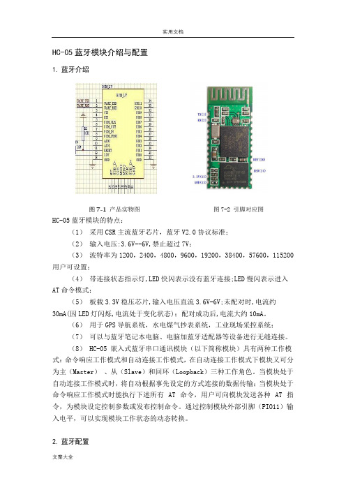
HC-05蓝牙模块介绍与配置1.蓝牙介绍图7-1产品实物图图7-2 引脚对应图HC-05蓝牙模块的特点:(1)采用CSR主流蓝牙芯片,蓝牙V2.0协议标准;(2)输入电压:3.6V--6V,禁止超过7V;(3)波特率为1200,2400,4800,9600,19200,38400,57600,115200 用户可设置;(4)带连接状态指示灯,LED快闪表示没有蓝牙连接;LED慢闪表示进入AT命令模式;(5)板载3.3V稳压芯片,输入电压直流3.6V-6V;未配对时,电流约30mA(因LED灯闪烁,电流处于变化状态);配对成功后,电流大约10mA。
(6)用于GPS导航系统,水电煤气抄表系统,工业现场采控系统;(7)可以与蓝牙笔记本电脑、电脑加蓝牙适配器等设备进行无缝连接。
(8) HC-05 嵌入式蓝牙串口通讯模块(以下简称模块)具有两种工作模式:命令响应工作模式和自动连接工作模式,在自动连接工作模式下模块又可分为主(Master)、从(Slave)和回环(Loopback)三种工作角色。
当模块处于自动连接工作模式时,将自动根据事先设定的方式连接的数据传输;当模块处于命令响应工作模式时能执行下述所有 AT 命令,用户可向模块发送各种 AT 指令,为模块设定控制参数或发布控制命令。
通过控制模块外部引脚(PIO11)输入电平,可以实现模块工作状态的动态转换。
2.蓝牙配置(1)主要内容所需材料:USB转TTL模块(下载器)、HC-05蓝牙模块一对、串口调试助手。
配置要求:实现两个蓝牙模块的主从绑定。
注意事项:设置步骤✧进入AT指令模式(所有AT指令都必须换行)✧设置串口波特率9600,无校验位,无停止位✧修改蓝牙名称、密码✧设置蓝牙的主从模式(1主1从)✧实现主从模块的绑定(两个模块实现透传)(2)操作实例A.用杜邦线连接好USB转TTL模块(下载器)与HC-05蓝牙模块(注意交叉!!)B.进入AT指令模式✧将下载器与电脑连接,(按住HC-05上的复位键,再接通电源,发现指示灯缓慢闪灭,表示进入AT指令模式),并且打开串口助手。
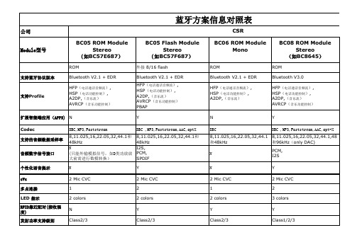
CSR蓝牙方案信息对照表
特需功能输入口 工作电压范围 预估价格范围
N 2.7 ~4.4v
N 2.7 ~4.4v
N 2.7 ~4.4v
N 2.7 ~4.4v
应用
适用于中端产品,如: 1,立体声耳机。 2,立体声迷你便携音箱。 3,汽车蓝牙套件。
适用于高端产品,如: 1,立体声耳机。 2,立体声迷你便携音箱。 3,汽车蓝牙套件。 4,大功率无线音箱。 可以实现: A,PCM信号的DSP处理。 B,RFID无线射频识别,非接触式的 自动识别,与NFC类似。 C,IOS设备可显示电池供电情况。 D,GAIA应用程序。
蓝牙方案信息对照表
公司 BC05 ROM Module Stereo (如BC57E687)
ROM 支持蓝牙协议版本 Bluetooth V2.1 + EDR HFP(电话通话音频流), HSP(电话功能控制), A2DP,(音乐流) AVRCP(音乐功能控制)
CSR BC05 Flash Module Stereo (如BC57F687)
6 capacitive touch sensor inputs 2.7 ~4.4v
Module型号
BC06 ROM Module Mono
ROM Bluetooth V2.1 + EDR HFP(电话通话音频流), HSP(电话功能控制), A2DP,(音乐流)
BC08 ROM Module Stereo (如BC8645)
ROM Bluetooth V3.0 HFP(电话通话音频流), HSP(电话功能控制), A2DP,(音乐流) AVRCP(音乐功能控制) Y SBC ,MP3,Faststream,AAC,aptStereo (如BC8670)
内置16M flash Bluetooth 4.0 HFP(电话通话音频流), HSP(电话功能控制), A2DP,(音乐流) AVRCP(音乐功能控制) PBAP Y SBC ,MP3,Faststream,AAC,apt-X 8,11.025,16,22.05,32,44.1,48 和96kHz(Only DAC) I2S, PCM, SPDIF Y 2 Mic CVC 2 3 colors Y Class1/2/3
BC05 立体声蓝牙模块规格书

四.产品方块图:
VTL-1698A
cyd16988@
五.尺寸标注:
VTL-1698A
cyd16988@
VTL-1698A
六.管脚说明:
管脚号
名称
1,21,32,40,43, 48,56,58
GND
2
PIO1
3
PIO0
串口输出端 串口输出端 数字 IO 口 数字 IO 口 数字 IO 口 数字 IO 口 数字 IO 口 数字 IO 口 数字 IO 口 低电平复位端 调试端口 调试端口 调试端口 调试端口 接红色 LED,显示电源相关信息 接蓝色 LED,显示蓝牙工作状态相关信息 开关机/接听电话等多功能按键输入端 内置 DC-DC 输出电压,供主芯片使用,尽量不要外接其他器件以防干扰 电池供电(3.3-4.2V) 充电端口(5V) 左声道音频输差分出端 左声道音频输差分出端 右声道音频输差分出端 右声道音频输差分出端 右声道 MIC 差分输入端 右声道 MIC 差分输入端 左声道 MIC 差分输入端 左声道 MIC 差分输入端 MIC 工作偏置电压 数字 IO 口 数字 IO 口 天线接口
36
LED1
37
LED0
38
VREN
39
1.8V
41
VBAT
42
V_CHG
44
SPK_A_P
45
SPK_A_N
46
SPK_B_P
4MIC_B_P
50
MIC_B_N
51
MIC_A_P
52
MIC_A_N
53
MIC_BIAS
54
PIO3
55
PIO2
57
ANT
BLK-MD-HC-05蓝牙模块技术手册

HC-05蓝牙模块技术手册一.概述BLK-MD-HC-05蓝牙模块是专为智能无线数据传输而打造,采用英国CSR公司BlueCore4-Ext芯片,遵循V2.0+EDR蓝牙规范。
本模块支持UART,USB,SPI,PCM,SPDIF等接口,并支持SPP蓝牙串口协议,具有成本低、体积小、功耗低、收发灵敏性高等优点,只需配备少许的外围元件就能实现其强大功能。
二.特点:蓝牙V2.0+EDR蓝牙Class2内置PCB射频天线内置8Mbit Flash支持SPI编程接口支持UART,USB,SPI,PCM等接口支持主从一体支持软件控制主从模块3.3V电源通过REACH、ROHS认证三.应用领域:该模块主要用于短距离的数据无线传输领域。
可以方便的和PC机的蓝牙设备相连,也可以两个模块之间的数据互通。
避免繁琐的线缆连接,能直接替代串口线。
※蓝牙车载免提※蓝牙GPS※蓝牙PCMCIA,USB Dongle※蓝牙无线数据传输;※工业遥控、遥测;※POS系统,无线键盘、鼠标;※交通,井下定位、报警;※自动化数据采集系统;※无线数据传输;银行系统;※无线数据采集;※楼宇自动化、安防、机房设备无线监控、门禁系统;※智能家居、工业控制;※汽车检测设备;※电视台的互动节目表决设备;※政府路灯节能设备※无线LED显示屏系统※蓝牙操纵杆、蓝牙游戏手柄※蓝牙打印机※蓝牙遥控玩具四.物理特征:Operating Frequency Band 2.4GHz ISM bandBluetooth Specification V2.0+EDROutput Power Class Class2Operating Voltage 3.3VHost Interface USB1.1/2.0or UARTAudio Interface PCM interfaceFlash Memory Size8MbitDimension27mm(L)x13(W)mm x2mm(H)五.电气特征:Absolute Maximum RatingsRating Min Max Storage temperature-40℃+150℃Supply voltage:VBAT-0.4V 5.6V Other terminal voltages VSS-0.4V VDD+0.4VRecommended Operating ConditionsOperating Condition Min Max Operating temperature range-40℃+150℃Guaranteed RF performance range(a)-40℃+150℃Supply voltage:VBAT 2.2V 4.2V(b)六.功耗:Operation Mode Connection Type UART Rate(kbps)Average Unit Page scan-115.20.42mAACL No traffic Master115.2 4.60mA ACL With file transfer Master115.210.3mA ACL1.28s sniff Master38.40.37mA ACL1.28s sniff Slave38.40.42mA SCO HV330ms sniff Master38.419.8mA SCO HV330ms sniff Slave38.419.0mA Standby Host connection-38.440µA七.功能框图:八.应用电路图:注意:该应用电路图为蓝牙串口电路,如需要其他应用方案,请联系客服。
蓝牙模块HC-05使用说明
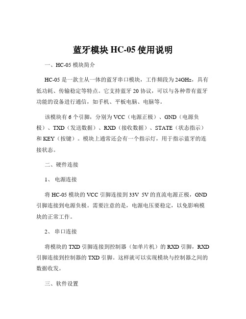
蓝牙模块HC-05使用说明一、HC-05 模块简介HC-05 是一款主从一体的蓝牙串口模块,工作频段为 24GHz,具有低功耗、传输稳定等特点。
它支持蓝牙 20 协议,可以与各种带有蓝牙功能的设备进行通信,如手机、平板电脑、电脑等。
该模块有 6 个引脚,分别为 VCC(电源正极)、GND(电源负极)、TXD(发送数据)、RXD(接收数据)、STATE(状态指示)和 KEY(按键)。
模块上通常还会有一个指示灯,用于指示蓝牙的连接状态。
二、硬件连接1、电源连接将 HC-05 模块的 VCC 引脚连接到 33V 5V 的直流电源正极,GND 引脚连接到电源负极。
需要注意的是,电源电压要稳定,以免影响模块的正常工作。
2、串口连接将模块的 TXD 引脚连接到控制器(如单片机)的 RXD 引脚,RXD 引脚连接到控制器的 TXD 引脚。
这样就可以实现模块与控制器之间的数据收发。
三、软件设置1、进入 AT 指令模式在使用 HC-05 之前,需要先将其设置为 AT 指令模式。
通常的方法是在模块未连接状态下,将 KEY 引脚拉低(接 GND),然后给模块上电,此时模块进入 AT 指令模式,指示灯会快速闪烁。
2、常用 AT 指令`AT`:测试指令,返回`OK`表示模块正常工作。
`AT+NAME=xxxx`:设置蓝牙模块的名称为`xxxx`。
`AT+BAUD=x`:设置波特率,`x`可以是 9600、19200、38400 等常见值。
`AT+PIN=xxxx`:设置配对密码为`xxxx`。
3、保存设置设置完成后,使用`AT+SAVE`指令保存设置,使设置在模块重新上电后仍然有效。
四、与手机或电脑配对连接1、打开手机或电脑的蓝牙功能,搜索附近的蓝牙设备,找到您设置好名称的 HC-05 模块。
2、输入设置好的配对密码进行配对连接。
3、连接成功后,模块的指示灯会常亮。
五、数据传输1、从 HC-05 发送数据控制器通过串口向 HC-05 发送数据,HC-05 会将数据通过蓝牙发送到已连接的设备。
BT-HC05-V1.0蓝牙模块用户手册

通讯中:5~20mA
(根据串口通讯频繁度不同而不同)
模块展示
主
简
从
单
一
易
体
用
名称 VCC GND TXD RXD KEY LED
引脚说明
说明 电源(3.3V~5V)
地 模块串口发送引脚(TTL电平,不能接RS232电平) 模块串口接收引脚(TTL电平,不能接RS232电平) 高电平进入AT状态,低电平或者悬空则进入正常状态。
参数说明
名称 接口说明 波特率 通讯距离 对外接口 工作电压
工作电流
参数 TTL电平,兼容3.3v/5v单片机 4800/9600(默认)/19200/38400/57600 /115200/230400/460800/921600/138240 10m(空旷地) 6pin排针(2.54间距) 3.3V~5V 配对中:30~40mA;
配对成功输出高电平,未成功输出低电平。
与单片机或者串口转USB模块连接方式
1.蓝牙模块与串口转USB模块对接连接方式:
USB
5v 3.3v
USB转TTL TXD RXD
蓝牙模块
GND
VCC
2.蓝牙模块与单片机通讯:
单片机
VCC TXD RXD
GND
LED
KEY
RXD TXD
常用AT指令
使用AT指令之前要进入AT指令模式。 建议进入AT指令模式的方式:上电前将KEY引脚连接到高电平,然后再上电。 进入AT指令后,波特率为38400(8位数据位,1停止位)。
指令1:修改蓝牙模块名字:AT+NAME=<name><回车>
例如:AT+NAME=Beetle<回车> 模块返回:0K
hc05蓝牙模块通信协议

hc05蓝牙模块通信协议HC05蓝牙模块通信协议甲方(以下简称“供应商”):公司名称:XXX有限公司公司地址:XXX省XXX市XXX区XXX路XXX号法定代表人:XXX联系电话:XXX-XXXXXXX乙方(以下简称“客户”):公司名称:XXX有限公司公司地址:XXX省XXX市XXX区XXX路XXX号法定代表人:XXX联系电话:XXX-XXXXXXX一、双方基本信息1.1 供应商提供的产品名称:HC05蓝牙模块1.2 供应商提供的服务内容:提供HC05蓝牙模块及相关服务1.3 供应商提供的售后服务:提供产品售后服务及技术支持1.4 客户使用的目的:XXX二、各方身份、权利、义务、履行方式、期限、违约责任2.1 供应商的身份:供应商是一家专业生产蓝牙模块的公司,具有合法的营业执照和生产许可证。
2.2 供应商的权利:供应商有权要求客户提供真实、准确、完整的联系方式和需求,并根据客户提供的信息提供服务。
供应商有权对本协议进行解释。
2.3 供应商的义务:供应商应按照本协议的约定为客户提供产品和服务。
供应商应按照协议约定履行售后服务和技术支持。
2.4 供应商的履行方式:供应商应在客户付款后7个工作日内,将产品交付客户。
供应商应提供产品的技术参数、产品说明书、使用手册等相关资料。
2.5 供应商的期限:本协议有效期为XX年,自双方签字盖章之日起生效。
2.6 供应商的违约责任:若供应商未能按照本协议的约定向客户提供产品和服务,应承担相应的违约责任。
2.7 客户的身份:客户是一家XXX公司,具有合法的营业执照和经营许可证。
2.8 客户的权利:客户有权要求供应商按照协议约定提供产品和服务。
客户有权使用产品及其配套设备,并参加供应商提供的相应培训。
2.9 客户的义务:客户应按照本协议的约定向供应商提供真实、准确、完整的联系方式和需求。
客户应按照协议约定支付货款并履行相关义务。
2.10 客户的履行方式:客户应按照协议约定支付货款。
HC-A05 蓝牙模块规格书
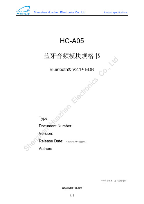
HC-A05蓝牙音频模块规格书Bluetooth®V2.1+EDRType:Document Number:Version:Release Date:(2013-03-01最新版)Authors:※如有新版本,恕不另行通知。
一、产品概述HC-A05蓝牙模块采用世界领先的蓝牙芯片供应商CSR公司的BlueCore5系列芯片,低成本、低功耗,是高质量立体声蓝牙耳机和音乐无线扬声器等产品的最佳选择。
Figure1:HC-A05蓝牙模块二、产品特点采用CSR原厂BC05系列芯片支持蓝牙规格V2.1+EDR支持CVC消除回音和噪声支持UART接口支持SPI编程接口符合RoHS标准LED指示蓝牙的运行状态安全认证、数据加密模块尺寸:20×13×2.2mm三、应用领域立体声蓝牙耳机无线立体声扬声器AV耳机汽车免提组件USB DONGLEF四、产品特性NO.项目特性1蓝牙协议版本Bluetooth specification V2.1+EDR Compatible V2.0,V1.2,V1.12晶体频率26MHZ3频率范围 2.4~2.48GHz4调制方式GFSK,1Mbps,0.5BT Gaussian5最大数据传输速率Asynchronous:723.2kbps/57.6kbps Synchronous:433.9kbps/433.9kbps6通讯距离10meters(33feet)Class II7接收灵敏度-80dBm@0.1%BER8安全特性Authnticaton and encryption9支持蓝牙协议HSP,HFP,A2DP,AVRCP,FTP,SPP,BPP,OPP,OBEX 10工作电压 1.8V or3.3V11工作电流20mA Typical at DH512待机电流≤1mA13操作温度0°C to+70°C14对外接口UART,PIO,SPI,Speaker,Microphone16模快尺寸20mmx13mmx2.2mm17音频编码位16bits18音频性能High acoustic fidelity sound五、框图Figure2:HC-A05蓝牙模块系统框图六、模块尺寸和管脚定义7.1模块尺寸模块尺寸:20x13x2.2mmUnit:mmFigure3:HC-A05蓝牙模块尺寸和脚位排列7.2管脚定义管脚脚位定义管脚类型功能描述1AIO0Bi-directional Programmable input/output line2GND2GND Ground3UART-RX CMOS input withweak internal pull-downUART Data Input(Active High)4UART-TX CMOS output,tristatewithweekinternal pull-upUART Data Output(Active High)5UART-RTS CMOS output,tristate,withweak internal pull-upUART Request To Send(Active Low)6UART-CTS CMOS input with weakinternal pull-downUART Clear To Send(Active Low)7PIO9Bidirectional withprogrammable strengthinternal pull-up/downProgrammable input/output line8PIO11Bidirectional withprogrammable strengthinternal pull-up/downProgrammable input/output line91V8POWER+1.8V Supply10RESET Input with weak internal pullupReset if low.Input debounced so mustbe low for>5ms to cause a reset.11PIO12Bidirectional withprogrammable strengthinternal pull-up/downProgrammable input/output line12PIO13Bidirectional withprogrammable strengthinternal pull-up/downProgrammable input/output line13PIO14Bidirectional withprogrammable strengthinternal pull-up/downProgrammable input/output line14PIO5Bidirectional withprogrammable strengthinternal pull-up/downProgrammable input/output line15PIO4Bidirectional withprogrammable strengthinternal pull-up/downControl output for external PA(Iffitted)16SPI-MOSI Input with weak internalpulldownSPI data input17SPI-CLK Bidirectional with weakinternal pull-downSPI clock18SPI-CSB Bidirectional with weakinternal pull-downChip select for SPI,active low19SPI-MISO Bidirectional with weakinternal pull-downSPI data output20LED0Open drain output LED driver21LED1Open drain output LED driver22POWER POWER Connect to1.8V23VBAT Battery terminal+ve Lithium ion/polymer battery positive terminal.Battery charger output and input to switch-mode regulator24GND5GND Ground25VCHG Charger input Lithium ion/polymer battery charger input26MIC-BIAS Analogue Microphone bias27MIC-B-P Analogue Microphone input,positive,channel B 28MIC-B-N Analogue Microphone input,negative,channel B29MIC-A-P Analogue Microphone input,positive,channel A 30MIC-A-N Analogue Microphone input,negative,channel A 31AGND GND Ground32SPK-B-N Analogue Speaker output,negative,channel B 33SPK-B-P Analogue Speaker output,positive,channel B 34SPK-A-N Analogue Speaker output,negative,channel A 35SPK-A-P Analogue Speaker output,positive,channel A36PIO3Bidirectional withprogrammable strengthinternal pull-up/downControl output for external PA(Iffitted)37GND GND Ground38ANT RF RF Interface 39GND3GND Ground40PIO0Bidirectional withprogrammable strengthinternal pull-up/downControl output for external PA(Iffitted)41PIO2Bidirectional withprogrammable strengthinternal pull-up/downControl output for external PA(Iffitted)42PIO1Bidirectional withprogrammable strengthinternal pull-up/downControl output for external PA(Iffitted)43AIO1Bi-directional Programmable input/output line七、电气特性7.1最大工作范围操作条件最小值理想值最大值存储温度-40°C25°C+150°C供应电压 2.7V 3.3V 3.6V7.2推荐工作范围工作条件最小理想值最大工作温度范围-40°C25°C+105°C 推荐工作温度范围-25°C25°C+85°C 供应电压 3.0V 3.3V 3.4V。
BC04-B蓝牙模块技术手册2.45

BC04-B蓝牙模块技术手册一.概述二.特点:蓝牙V2.1+EDR 蓝牙Class 2 内置PCB 射频天线 内置8Mbit Flash 支持SPI 编程接口支持UART,USB,SPI,PCM 等接口 支持主从一体支持软硬件控制主从模块 3.3V 电源支持连接7个从设备 通过REACH 、ROHS 认证三.应用领域:该模块主要用于短距离的数据无线传输领域。
可以方便的和PC 机的蓝牙设备相连,也可以两个模块之间的数据互通。
避免繁琐的线缆连接,能直接替代串口线。
※ 蓝牙无线数据传输; ※ 工业遥控、遥测;※ POS 系统,无线键盘、鼠标; ※ 交通,井下定位、报警; ※ 自动化数据采集系统; ※ 无线数据传输;银行系统; ※ 无线数据采集;※ 楼宇自动化、安防、机房设备无线监控、门禁系统; ※ 智能家居、工业控制; ※ 汽车检测设备;※ 电视台的互动节目表决设备;BC04-B 蓝牙模块是深圳市博陆科电子科技有限公司专为智能无线数据传输而打造,采用英国CSR 公司BlueCore4-Ext 芯片,遵循V2.1+EDR 蓝牙规范。
本模块支持UART,USB,SPI,PCM,SPDIF 等接口,并支持SPP 蓝牙串口协议,具有成本低、体积小、功耗低、收发灵敏性高等优点,只需配备少许的外围元件就能实现其强大功能。
※政府路灯节能设备※无线LED显示屏系统※蓝牙操纵杆、蓝牙游戏手柄※蓝牙打印机※蓝牙遥控玩具四.物理特征:五.电气特征:六.功耗:七.功能框图:八.应用电路图:注意:该应用电路图为蓝牙串口电路,如需要其他应用方案,请联系博陆科电子。
九.管脚功能描述:十.外形尺寸:十一.主从设置及其他配置模块主从模式设置:BC04-B蓝牙模块同时支持软/硬件设置主从模式,具体方法如下:PI0(4)——软/硬件主从设置口:置低(或悬空)为硬件设置主从模式,置3.3V高电平为软件设置主从模式;如选择硬件设置主从模式,可通过PIO(5)进行设置;如果选择软件设置主从模式,可以通过AT命令查询和设置,具体方法参考《BC04-B蓝牙模块AT指令说明》PIO(5)——硬件主从设置口:3.3V高电平设置主模式,接地(或悬空)设置从模式。
MLT-BT05模块手册
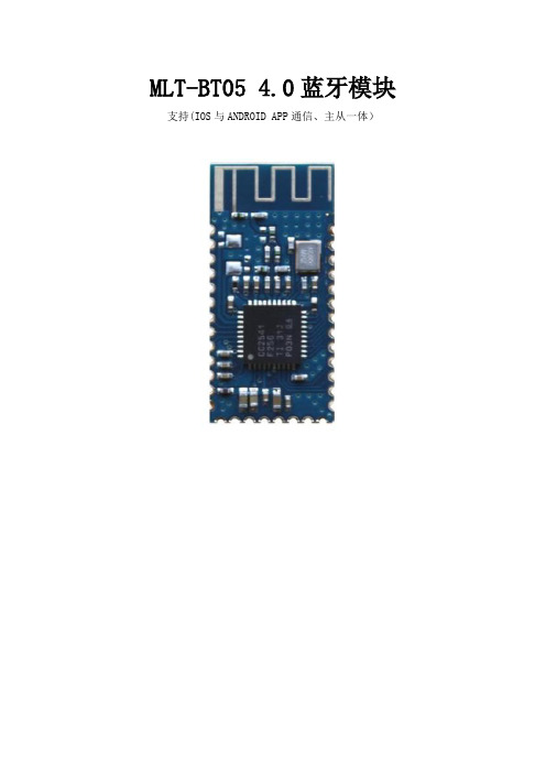
MLT-BT05 4.0蓝牙模块支持(IOS与ANDROID APP通信、主从一体)
一.应用电路图
二.管脚功能描述
三.封装尺寸:
四.功能引脚说明
1、主从设置
28 脚——硬件主从设置口:3.3V 高电平设置主机透传模式,接地或悬空从机透传。
2、LED指示
3 、唤醒模块设置:
方法一:短按系统按键 SW1(23脚P13引脚)。
短按:
方法二:直接配对连接。
五.LAYOUT 注意事项
MLT-BT05 4.0蓝牙模块工作在2.4G 无线频段,应尽量避免各种因素对无线收发
的影响,注意以下几点:
1、包围蓝牙模块的产品外壳避免使用金属,当使用部分金属外壳时,应尽量让
模块天线部分远离金属部分。
2、产品内部金属连接线或者金属螺钉,应尽量远离模块天线部分。
3、模块天线部分应靠载板PCB 四围放置,不允许放置于板中,且天线下方载
板铣空,与天线平行的方向,不允许铺铜或走线。
直接把天线部分直接露出
载板,也是比较好的选择。
4、模块下方尽量铺大片GND,走线尽量往外围延伸。
5、建议在基板上的模块贴装位置使用绝缘材料进行隔离,例如在该位置放一个
整块的丝印(TopOverLay)。
03A-BC5规格书
≦0.02
mA
b)ST-BYAVERAGECURRENT待机平均电流
1
-
mA
c) SEARCH PAIRINGCURRENT配对电流
15
<20
mA
d) TALK MODE CURRENT通话电流(最大音量档)
28
<35
mA
e) AV MODE CURRENT AV服务电流(最大音量档)
43
Product Specification
Model:03A
DRAWN BY:
MODEL :
03A
CHECKED BY:
DESCRIPTION:
APPD. BY:
PAGE :
MEASUREMENT CONDITION
1) STANDARD VOLTAGE : DC3.7V +/-0.1V
ChargerUNIT:AC220V +/-5V60 Hz( @300mA/5。5VDC)
Battery monitoring Period电池检测周期:30 S
LOW BATT 低电报警:3.5 +/-0.1V
BATTERY SPEC 电池规格:492530 320Ma
TRANSMITTER ( PCBA )TX 发射测试
DESCRIPTION
CENTER
LIMIT
UNIT
a) TXCENTERFREQUENCY发射中心频率(CH39)
b) 串音 (参考样机)
-50
<-45
dB
c)DISTORTION AT SPK接收失真
(MIC IN 179mV ,With SPK Loading& Audio Gateway)
蓝牙车载CSR BC5 Flash规格书
功能特点: 二、 二、功能特点:
� 主芯片:CSR BC57E687B (BlueCore5-MM) � 蓝牙版本:V2.1+EDR � 输出功率:Class 2 � RF输出功率:4dBm � 传输距离:视距10米 � FLASH存储容量:8-16Mbit � 尺寸:30.4mm*15.5mm*2.2mm � Rohs 标准:符合
Tel:0755-23906926 Fax:0755-29487827
4、模块下方尽量铺大片GND,走线尽量往外围延伸。(如上图)
Tel:0755-23906926 Fax:0755-29487827
PIO5 PIO6 PCMIN PCMCLK PCMSYNC PCMOUT SPI_CLK
Programmable input/output line Programmable input/output line Synchronous data input Synchronous data clock Synchronous data sync Synchronous data output SPI clock Chip select for Serial Peripheral SPI_CS Interface (SPI),active low SPI_MOSI SPI data input SPI_MISO SPI data output GND Ground connection for internal 3.7V Lithium ion/polymer battery positive BAT terminal. Battery charger output and input to switch-mode regulator LED[1] LED driver LED[0] LED driver VBUS Lithium ion/polymer battery charger (5V) PIO2 Programmable input/output line PIO3 Programmable input/output line MIC_BIAS Microphone bias SPKR_A_N Speaker output negative, left MIC_B_P Microphone input positive, right MIC_A_P Microphone input positive, left SPKR_B_N Speaker output negative, right Positive supply output for audio 1V5 AUDIO circuitry and 1.5V regulated output MIC_B_N Microphone input negative, right MIC_A_N Microphone input negative, left SPKR_B_P Speaker output positive, right SPKR_A_P Speaker output positive, left PIO0 Programmable input/output line
UCTRONICS Arduino Smart Bluetooth Robot Car 套件说明书

Arduino Smart Bluetooth Robot CarKitUser GuideTable of Contents1. Introduction (4)1.1 Packing list (5)2. Assembly (6)2.1 Arduino Uno R3 (6)2.1.1 Specifications (6)2.2 HC-SR04 Ultrasonic Sensor Module with Bracket / Holder (7)2.2.1 Working Principle (7)2.2.2 Specification (8)2.2.3 Wiring diagram: (9)2.3 L293D Motor Drive Expansion Board for Arduino (9)2.3.1 Specification (9)2.4 SG90 9g micro small servo motor (10)2.4.1 Specification (11)2.5 2WD Driver Motor Encoder Robot Smart Car Chassis Kits (11)2.5.1 Specification (11)2.6 HC-05 Bluetooth Serial transmission Wireless Module (12)2.6.1 Specification (12)2.6.2 Pin definition (13)2.6.3 Application: (13)2.7 Infrared IR Wireless Remote Control Sensor Module Kits (14)2.7.1 Specification (14)2.7.2 Dimension (15)3. Pin Definition (16)4. Wiring (17)5. Installation (18)5.1 Installation of the Components (18)5.2 Installation of the Car (20)6. Key Value for Remote Controller (27)7. Start Programing (28)7.1 Install Arduino IDE (28)7.2 Add Libraries (32)8. Bluetooth App for Android (35)Step 1: Download and Install App (35)Step 2: Open UCTRONICS_Car_Controller software, the default is Bluetooth Mode (36)Step 3: Click the top right and choose ‘Connected device‘ (36)Step 4: Select ‘CAR CONTROL MODE’ (37)Step 5: Search Bluetooth Device (37)Step 6: Enter control menu (38)Step 7: Click the top right and choose ‘Change to wifi mode’ (38)1. IntroductionThe UCTRONICS Smart Bluetooth Robot Car Kit is a flexible vehicular kit particularly designed for education, competition and entertainment.The kit has an intelligence built in so that it guides itself whenever an obstacle comes ahead of it. An Arduino development is used to achieve the desired operation. With the help of a small servo motor, it scans the area left and right in order to find the best way to turn. An ultrasonic sensor unit is used to detect any obstacle ahead of it that sends a command to the Arduino Board. Depending on the input signal received, the Arduino microcontroller redirects the robot to move in an alternate direction by appropriately actuating the motors interfaced to it through a motor driver IC.When all the necessary components are getting together, a robot car comes up!A robot is a machine that can perform some task automatically or with guidance. Robotics is generally a combination of computational intelligence and physical machines (motors). Due to their high level of performance and reliability, the robot get the splendid popularity in our daily life.Come up, let’s go into a Robot World!1.1 Packing list1pcs Arduino UNO R3 Board1pcs HC-SR04 Ultrasonic Sensor Module1pcs Holder for HC-SR041pcs L293D Motor Drive Expansion Board1pcs 9g micro servo motor1pcs servo motor Bracket1pcs Infrared IR Wireless Remote Control Sensor Module Kits 1pcs HC-05 Bluetooth Serial transmission Wireless Module Some cables and pin headers as a gift1set Car Chassis Kits:●2pcs 65mm tire Wheels●2pcs Geared Motors (1:48)●2pcs Speed Encoders●1pcs Universal Wheel●1pcs Battery Box●1pcs Car Chassis●1pcs Switch●Screws+ Nuts2. Assembly2.1 Arduino Uno R3This is the new Arduino Uno R3. In addition to all the features of the previous board, the Uno now uses an ATmega16U2 instead of the 8U2 found on the Uno (or the FTDI found on previous generations). This allows for faster transfer rates and more memory. No drivers needed for Linux or Mac (.inf file for Windows is needed and included in the Arduino IDE), and the ability to have the Uno show up as a keyboard, mouse, joystick, etc.The Uno R3 also adds SDA and SCL pins next to the AREF. In addition, there are two new pins placed near the RESET pin. One is the IOREF that allow the shields to adapt to the voltage provided from the board. The other is a not connected and is reserved for future purposes. The Uno R3 works with all existing shields but can adapt to new shields which use these additional pins.Note: The Arduino Uno R3 requires the Arduino 1.0 drivers folder in order to install properly on some computers. We have tested and confirmed that the R3 can be programmed in older versions of the IDE. However, the first time using the R3 on a new computer, you will need to have Arduino 1.0 installed on that machine. If you are interested in reading more about the changes to the IDE, check out the official Arduino 1.0 Release notes!2.1.1 SpecificationsMicrocontroller: ATmega328Operating Voltage: 5VInput Voltage (recommended): 7V-12VInput Voltage (limits): 6V-20VDigital I/O Pins: 14 (of which 6 provide PWM output)Analog Input Pins: 6DC Current per I/O Pin: 40 mADC Current for 3.3V Pin: 50 mAFlash Memory: 32 KB (ATmega328) of which 0.5 KB used by bootloaderSRAM: 2 KB (ATmega328)EEPROM: 1 KB (ATmega328)Clock Speed: 16 MHz2.2 HC-SR04 Ultrasonic Sensor Module with Bracket / HolderThe HC-SR04 ultrasonic sensor module for Arduino is used for obstacle detection. Ultrasonic sensor transmits the ultrasonic waves from its sensor head and again receives the ultrasonic waves reflected from an object.Ultrasonic sensor general diagram2.2.1 Working PrincipleThe ultrasonic sensor emits the short and high frequency signal. These propagate in the air at the velocity of sound. If they hit any object, then they reflect back echo signal to thesensor. The ultrasonic sensor consists of a multi vibrator, fixed to the base. The multi vibrator is combination of a resonator and vibrator. The resonator delivers ultrasonic wave generated by the vibration. The ultrasonic sensor actually consists of two parts; the emitter which produces a 40kHz sound wave and detector detects 40 kHz sound wave and sends electrical signal back to the microcontroller.Ultrasonic working principleThe ultrasonic sensor enables the robot to virtually see and recognize object, avoid obstacles, measure distance. The operating range of ultrasonic sensor is 2 cm to 450 cm.2.2.2 SpecificationWorking Voltage: 5V DCStatic current: < 2mAOutput signal: Electric frequency signalOutput Voltage: 0V-5VSensor angle: <= 15°Detection distance: 2-450cmHigh precision: Up to 0.3cmInput trigger signal: 10us TTL impulseEcho signal: output TTL PWL signalMode of connection: VCC, trig (T), echo, GNDUsing method:(1) Supply module with 5V(2) Output will be 5V while obstacle in range, otherwise it will be 0VItem size: 44x20x15mm2.2.3 Wiring diagram:2.3 L293D Motor Drive Expansion Board for ArduinoThis is a commonly used DC motor drive module, using L293D chip with small current DC motor driver. The pins are made compatible with Arduino which is easy to use.2.3.1 Specification2 connections for 5V servos connected to the Arduino's high-resolution dedicated timer Up to 4 bi-directional DC motors with 4 PWM speed regulationUp to 2 stepper motor control, single / double step control, staggered or microsteppingand rotation angle control4 H-Bridges: L293D chipset provides 0.6A per bridge (1.2A peak) with thermal shutdown protection, 4.5V to 36VPull down resistors to keep motors in the state of rest during power-upLarge terminal terminals make wiring easier (10 - 22AWG)With Arduino reset buttonThe 2 terminals are connected to the external power supply terminals to ensure the separation of the logic and the motor drive power2.4 SG90 9g micro small servo motorSG90 9g micro small servo motor is the main source of controlling action of the remote-control model. The module is widely applied in the field of fixed wing, helicopter,gliding, small robot, manipulator model.2.4.1 SpecificationSize: 23x12.2x29 mmTorsional moment: 1.5kg/cmWorking voltage: 4.2V-6VTemperature range: 0℃-55℃Operating speed: 0.1 seconds /60°Dead band width: 10 microseconds2.5 2WD Driver Motor Encoder Robot Smart Car Chassis KitsWith the car platform, adding micro-controller (such as Arduino) and sensor modules, then program it, a robot car comes up.All the module interface has been modified with XH2.54 ports as to make it much easier and convenient to assemble the car and reduce the chances for errors.2.5.1 SpecificationThe car is the tachometer encoderWith battery boxGear Motor reduction radio: 48:1Apply in distance measurement, velocity2.6 HC-05 Bluetooth Serial transmission Wireless ModuleThis module is mainly used in the field of wireless transmission of data over short distances. It can be easily connected to PC Bluetooth device and also can exchange data between two modules. Direct serial cable replacement avoid the cumbersome cable connections.2.6.1 SpecificationInterface: VCC, GND, TXD, RXD, KEY, STATE (Note: The Pin for STATE, low output when unconnected, high out when after the connection)LED indicates the connection state of the Bluetooth, quick flash indicates no connection, slow flash indicates the module enter into the AT mode, double flash indicates the successfully connection of the Bluetooth and the open portThe bottom plate is set to an anti-reverse diode with 3.3V LDO, the input voltage 3.6-6V, unpaired current is 30mA, 10mA after pairing, the input voltage is prohibited more than 7VInterface level 3.3V which can be directly connected to a variety of single-chip (51, AVR, PIC, ARM, MSP430, etc.), 5V microcontrollers can also be directly connected which can not pass through MAX232 chipAvailable to pull the 34 feet into the AT command mode setting parameters andsearching informationAvailable to use AT command to switch to the host or slave mode and connect to the specified deviceBaud rate: 4800bps ~ 1382400bpsSize: 3.57x1.52cm2.6.2 Pin definition2.6.3 Application:Bluetooth printers, wireless data collection, Bluetooth remote control toys, automotive testing equipment, industrial control, telemetry, Bluetooth wireless data transmission traffic, underground location, alarmPOS systems, wireless keyboard, mouse, automation, data acquisition systems, wireless data transmission, the banking system, the government lights energy-saving equipment, interactive television program, voting equipment, wireless LED display systemBluetooth joystick, Bluetooth game controller, intelligent home, industrial control, building automation, security, wireless monitoring and control room equipment, access control systems2.7 Infrared IR Wireless Remote Control Sensor Module KitsThe wireless infrared remote controlling kits by mini ultra-thin infrared remote controller and LF0038M infrared receiving module, mini slim infrared remote control with 17 function keys and launch the farthest distance up to 8 meters, it is suitable for the indoor control a variety of devices. The infrared receiving module can receive the remote control signal which is modulated by the standard 38 KHz, and the decoding operation of the remote control signal can be realized by programming the remote control signal.2.7.1 SpecificationRemote control:8 address bit, 8 order bitCarrier frequency: 38kHzTransmission Distance: up to 8mSticking material: 0.125mmPETLift cycle: 20,000 timesLF0038M infrared receiver:Operating voltage: 2.7V-5.5VReceiving distance: 15m-18mOutput: TTL, CMOS level, active lowAnti-dry abilityEpoxy plastic encapsulation2.7.2 DimensionInfrared receiver3. Pin DefinitionArduino UNO R3 BoardL293D Motor Drive Expansion Board4. Wiring5. Installation5.1 Installation of the Components Step 1Step 2Step 3Step 45.2 Installation of the CarStep 1: Install the deceleration DC motor to the chassisStep 2: Install the hammer casterStep 3: Fix the wheelStep 4: Connect the servo to the motor drive boardStep 5: Install the ultrasonic bracketStep 6: Install the ultrasonic moduleStep 7: Connect the infrared sensorStep 8: Place the battery containerStep 9: Connect remote controller wire to the motor drive boardStep 10: Install the HC-05 Bluetooth moduleStep 11: Connect the motor drive board to the deceleration DC motor6. Key Value for Remote Controller7. Start Programing7.1 Install Arduino IDEStep 1:Go to the website and click Software. On the page, check the software list on the right side under Download the Arduino SoftwareFind the one that suits your operation system and click to download. There are two versions of Arduino for Windows: Installer or ZIP file. You're recommended to download the former Step 2:Press the button ‚JUST DOWNLOAD‛ to download the softwareStep 3:Double click the .exe file and the following window will show up. Click ‚I Agree‛NextStep 4: Click ‚Browse‛ to choose the installation path or enter a directory at the Destination Folder. Click ‚Install‛ to initiate installationStep 5:After the installing progress bar goes to the end, the ‚Close button‛ may be enabled for some PC. Just click it to complete the installationStep 6: Then a prompt appears. Select Always trust software for "Adafruit Industries" and click ‚Install‛Step 7: After the installation is done, click Close. Then an Arduino icon will appear on the desktop:7.2 Add LibrariesStep 1: Download and unzip the filehttps:///UCTRONICS/Smart-Robot-Car-Arduino.gitStep 2: Open the documents ‚Smart-Robot-Car-Arduino-master‛And then, Copy ‚Arducam_Smart_Robot_Car‛ to .. \ Arduino \ libraries (under the installation path of Arduino)Open the ‚Install Library‛copy ‚AFMotor‛, "NewPing‛ to .. \ Arduino \ libraries (under the installation path of Arduino)Step 3:O pen Arduino IDE, click ‚Tools‛->‚Board: Arduino/Genuino Uno‛->‚Arduino/Genuino Uno‛Step 4:Click ‚Tool‛ to select the serial portStep 5:Click ‚File‛ to select the libraryPlease note that the Arducam smart robot car V1 support smart mode, Arducam smart robot car V2 add the support of Bluetooth control and IR controlStep 6:Compile and downloadPlease note that before compiling, you should remove the HC-05 Bluetooth module8. Bluetooth App for AndroidStep 1: Download and Install Apphttps:///UCTRONICS/Smart-Robot-Car-Arduino/tree/master/BlueTooth%20ToolStep 2: Open UCTRONICS_Car_Controller software, the default is Bluetooth ModeStep 3: Click the top right and choose ‘Connected device‘Step 4: Select ‘CAR CONTROL MODE’Step 5: Search Bluetooth DeviceStep 6: Enter control menuStep 7: Click the top right and choose ‘Change to wifi mode’For examples and documentation, please visit:https:///UCTRONICS/Smart-Robot-Car-Arduino.gitIf any problems or suggestions for the tutorial or the robot car, please feel free to contact us by following ways:Skype: fpga4uTel: +86 025 ********Website: Email:*******************。
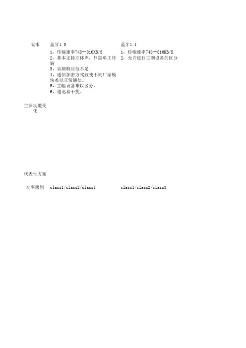
蓝牙版本对照表
版本蓝牙1.0蓝牙1.1主要功能变化1,传输速率748--810KB/S2,基本支持立体声,只能单工传输3,音频响应范不足4,通信加密方式致使不同厂家模块难以正常通信。
5,主辐设备难以区分。
6,通迅易干扰。
1,传输速率748--810KB/S2,允许进行主副设备的区分代表性方案功率级别class1/class2/class3class1/class2/class3蓝牙1.2蓝牙2.0+EDR蓝牙2.1+EDR1,传输速率748--810KB/S 2,增加了AFH抗干扰适应性跳频功能。
3,单功,半双功,双功传输。
4,ESCO技术,即延伸同步连接导向进一步满足更高阶语音与音迅产品需要。
5,用first FHS与interlaced scan两项技术来快速连接。
1,传输速率1.8--2.1M/S,EDR(enhanced date rate),传输速率提高3倍。
2,通过减少工作负载循环降低能源消耗,电池工作时间延长1倍。
3,降低了比特误差率,BER。
4,带宽的增加减化了多连接模式。
1,传输速率1.8--2.1M/S2,改善了配置流程来实再自动连接,具备两设备配对的NFC机制。
3,更省电,加入sniff,subraing功能(低耗电监听模式)。
休眼模式下相互确认连接的时间由0.1S改为0.5S,待机延长5倍。
BC05ROM/BC05flash/BC06ROMclass1/class2/class3class1/class2/class3class1/class2/class3蓝牙版本对照表蓝牙3.0蓝牙4.01,使用了802.11无线局域网协议,传输速度提高至约24M/S。
2,使用全新的交替射频技术AMP,允许消费类设备使用标准蓝牙射频和无线局域网射频(WIFI)多重传输。
(BT+3.0+HS)1,传输速率约24M/S以上。
2,BLE省电科技,极低的运行功耗。
比如一些产品上面一枚钮扣电池可用1-5年。
3,3ms低延迟100米以上超长距传输,AES-128加密。
- 1、下载文档前请自行甄别文档内容的完整性,平台不提供额外的编辑、内容补充、找答案等附加服务。
- 2、"仅部分预览"的文档,不可在线预览部分如存在完整性等问题,可反馈申请退款(可完整预览的文档不适用该条件!)。
- 3、如文档侵犯您的权益,请联系客服反馈,我们会尽快为您处理(人工客服工作时间:9:00-18:30)。
BC05
蓝牙音响/车载蓝牙模块规格书
Type:
Document Number: Version:
Release Date: Authors:
Release
1.0
MAY 6, 2010
1、导言
BC05 兼容蓝牙规格 2.0,它集成蓝牙射频,蓝牙 Baseband controller,蓝牙天线,在一个小巧 的封装之内,帮助客户省钱,省心 BOM 成本,节省空间。
BC05 支持,FTP,OBEX,OPP,SPP,A2DP,AVRCP 等蓝牙协议,用户可以非常容易地把此模块用 在自己的产品设计当中。
另外,BC05 提供丰富的附加软件设计,而且可以帮助客户定制软件。
2、应用领域
A、汽车免提电话
B、蓝牙立体声耳机
C、蓝牙 GPS 设备
D、汽车蓝牙音响
E、A/V USB DONGLE
F、液晶电视
G、SKYPE 电话
4、框图
Figure1:BC05 系统框图
BC05 基本上集成蓝牙应用的所有的器件:
兼容蓝牙 2.0 的规格
支持软件在线更新(UART/USB)
SUPPORT Piconet, up to 7 Slaves
提供 UART 接口,方便用户接口,用户使用 AT COMMAND 就可以控制蓝牙的运行状态:开机/关 机,上一个频道,下一个频道,音量增加,减少等等命令。
提供了音频接口:PCM/I2S/SPDIF,方便用户使用外置的 CODEC,比如 WM8731
内部 16 位立体声 CODEC
LED 指示蓝牙的运行状态
内置 1.8V 的 DC/DC
Size: 20mm x 13mm x 2mm
RoHS compliant
5、模块尺寸和管脚定义
Figure2:BC05 尺寸和脚位排列
6、接口规格说明
6.1 主控制接口:异步串行接口(UART)
BC05 模块的 UART_TX 和 UART_RX 是一个特如的异步串行接口,利用它,用户非常方 便的连接其他的具有 UART 的接口的芯片,比如 C51,电视机的控制 MCU 之类的。
其波特率可以调整, 从 9600Baud 到 115.2K Baud。
T
X BC05
RX RXD
TXD
HOST MCU
Figure3:BC05 与 HOST MCU 的通信接口设计
电视的 MCU 通过 UART 接口,可以通过 AT 命令,开控制蓝牙设备的运行状态,比如:来电显 示,蓝牙配对,接听电话,挂断电话,音量增加,音量减少等等,这些命令,用户只要按照一定的数据
格式,就可以最少的代码,实现用户所需要的功能。
具体使用格式是:
<CR><LF>AT+CMD<CR><LF>
<CR><LF>IND<CR><LF>
比如:进入配对,使用如下格式即可:
\\r\\nAT+AA\\r\\n
送给BC05,模块就会自动去搜索附近的蓝牙设备,搜索完之后,把每一个蓝牙设备告诉主机,供
客户选择恰当的蓝牙设备。
BC05 在出厂的时候,提供蓝牙安全码地址。
6.2 数字信号 PCM 接口
PCM 是一个三态双向通道的音频接口通道,具有 8,16,32,44.1,48K bit/s,PCM 编码格式有 8-
bit A-law, 8-bit µ-law, 13-bit linear or 16-bit linear,PCM_CLK 和 PCM_SYNC 端口可以被配制成输入或者输 出,依靠模块是 master 或者是 slave 的 PCM 接口。
目前 PCM 可以支持如下几种数据格式:I2S/SPDF PCM 可以直接和如下几个设备连起来配对:
Wolfson 的 WM8731
TI 的 TLV320AIC23B
PCM作为MASTER接口:PCM-CLK,PCM_SYNC由模块产生
BC05
Figure4:BC05 PCM 作为 MASTER 接口设计 PCM作为SLAVE的接口话,PCM-CLK的波特率只能是2480KHZ:
BC05
Figure5:BC05 PCM 作为 SLAVE 接口设计
7、应用原理图设计
Figure7:BC05 在 GPS/CAR KIT 应用原理图
8、BC05模组尺寸和脚位图:
(如下图)
11-
12-12。
