YJ型液压机械式随钻震击器中英文实体
QY型全液压随钻震击器使用说明

QY型全液压随钻震击器使用说明全液压随钻震击器是一种用于震击井口的设备,主要用于钻探工程中的钻杆解扣和管柱下降时的应急救援。
本文将详细介绍QY型全液压随钻震击器的使用说明。
一、操作前准备:1.检查设备:检查全液压随钻震击器是否完好无损,各零部件是否齐全,并对设备进行必要的润滑。
2.连接管道:将全液压随钻震击器与钻机井口连接的油管进行连接,确保连接牢固可靠,没有漏油。
二、使用操作步骤:1.全液压随钻震击器的操作步骤是根据钻机的工况来确定的,通常分为握杆拉桩和解扣两个阶段。
2.握杆拉桩:将全液压随钻震击器放置在井口,并通过钻杆高压油管连接到钻机主泵的高压油管上,将全液压随钻震击器的拉杆握紧在钻杆上。
3.解扣操作:当钻杆解扣时,需要紧急救援时,可使用全液压随钻震击器进行解扣。
此时,需要调整全液压随钻震击器的工作压力,使其达到最佳解扣效果。
打开全液压随钻震击器的主控制阀,通过控制手柄或按钮,使全液压随钻震击器开始工作。
震击器会根据设定的工作压力进行快速的震击,用于解扣管柱,此时注意安全操作,确保人员和设备安全。
4.解扣后的处理:在解扣完成后,需要关闭全液压随钻震击器的主控制阀,并将拉杆从钻杆上卸下。
将震击器放置在安全地方,并及时对设备进行清洁、维护,以确保下次使用时的良好状态。
三、注意事项:1.操作人员必须经过专业培训,并熟悉全液压随钻震击器的使用说明。
2.在操作过程中,严格按照操作步骤进行操作,确保人员和设备的安全。
3.定期对全液压随钻震击器进行维护和保养。
定期检查设备的润滑油、密封件等零部件的状况,及时更换损坏的零部件。
4.在操作过程中,如出现异常情况,应立即停止操作,并及时排查和处理故障。
5.严禁非专业人员擅自操作全液压随钻震击器。
对于未经过专业培训的人员,禁止进行操作,以免造成人员伤亡和设备损坏。
说明书-JYSZ机械液压震击器
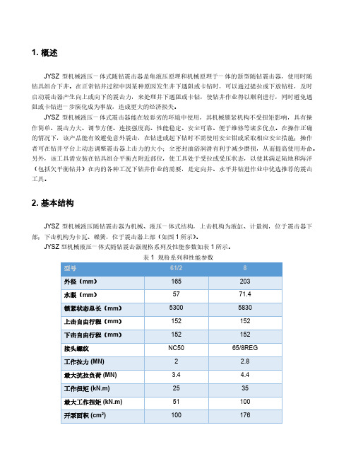
1. 概述JYSZ 型机械液压一体式随钻震击器是集液压原理和机械原理于一体的新型随钻震击器,使用时随钻具组合下井。
在正常钻井过程中因某种原因发生井下遇阻或卡钻时,可以通过提拉或下放钻柱,及时启动震击器产生向上或向下的震击力,来处理井下遇阻或卡钻,使钻井作业得以顺利进行,同时避免遇阻或卡钻进一步演化成为事故,造成更大的经济损失。
JYSZ 型机械液压一体式震击器能在较恶劣的环境中使用,其机械锁紧机构不受扭矩影响,具有操作简单、震击力大、调节方便、连接强度高、性能稳定、安全可靠、便于维修等诸多优点。
在操作正确的情况下,该产品能有效避免意外震击,在钻进或起下钻时不需使用安全钳或采取相应安全措施;操作者可在钻井平台上动态调整震击器上击力的大小;全密封油浴润滑有利于减少磨损,从而提高使用寿命。
另外,该工具需安装在钻具组合平衡点附近部位,使工具处于受拉或受压状态,以使其满足陆地和海洋(包括欠平衡钻井)在内的各种工况下钻井作业的需要,是定向井、水平井钻进作业中优选推荐的震击工具。
2. 基本结构JYSZ 型机械液压随钻震击器为机械、液压一体式结构,上击机构为液缸、计量阀,位于震击器下部;下击机构为卡瓦、碟簧,位于震击器上部(如图1所示)。
JYSZ 型机械液压一体式随钻震击器规格系列及性能参数如表1所示。
表1 规格系列和性能参数图1 JYSZ 型机械液压一体式随钻震击器结构示意图3. 工作原理3.1. 上击下放钻柱使震击器完全回位(处于锁紧位置)。
按从小到大吨位上提钻柱,迫使碟簧储能、液缸延时。
当芯轴上行到解除锁紧状态,钻柱中储存的弹性势能转换成向上的动能,产生上击。
震击完成后,提供足够的压力使震击器返回锁紧位置。
重复上述过程,可使工具再次上击。
3.2. 下击下压震击器使震击器完全回位(处于锁紧位置)。
下放钻柱,使碟簧压缩储能,当震击器所受压力大于震击器预定下击解锁力时,芯轴从卡瓦上脱出,解除锁紧状态,震击器芯轴迅速下移,产生下击。
钻井设备英语

Part One SLICK-LINE(钢丝作业)A. TOOLSrope socket 绳帽stem 加重杆roll stem 滚轮加重杆Tungsten stem 钨加重杆Lead stem 铅加重杆link jar 机械震击器tubular jar 管状震击器hydraulic jar 液压震击器spring jar 弹簧震击器knuckle joint 万向节swivel joint 旋转节wellhead adapter 井口变扣短节X-Over 变扣gauge cutter 通井规selective downshift tool 选择性滑套开关工具shiftting tool 移位工具blind box 盲锤L.I.B(lead impression block) 铅印swaging tool 胀管器spear 打捞矛prong grab 内捞矛center spear 外捞矛catcher 捕捉器wirefinder 钢丝探测器Go devil-F.B 平底撞棍Go devil-C.B 刀杆撞棍retriever 钢丝打捞器overshot 卡瓦打捞筒magnetic fishing tool 磁力打捞工具sidewall cutter 刮管刀alligator grab 鳄鱼爪sand bailer 捞沙筒pipe wrench 管钳tong chain 链钳spanner 扳手wireline clamp 钢丝夹hay pulley 地滑轮dump bailer 倾倒筒saw 锯子saw blade 锯条punch 冲子file 锉刀flat file 板锉,扁锉hammer 榔头pliers,vice 老虎钳wire cutter 断线钳forfex 剪刀tongs 大钳,钳子,管钳flat bit tongs 扁嘴钳screwdriver 改锥,螺丝刀wire stripper 剥皮钳,掳线钳wire-stripper pliers 剥线钳B. EQUIPMENTstuffing box 防喷盒lubricator upper section 上防喷管lubricator middle section 中防喷管lubricator lower section 下防喷管blowout preventer(BOP) 防喷器wellhead adapter 井口变扣短节Lincoln pump 林肯泵hand pump assy.for stuffing box 手压泵Fire extinguisher 灭火器hand tool box 手工具箱injector 注油器lifting cap BOP吊帽trolly 防喷管支撑架parasol 阳伞work vice 台钳chain block 链葫芦tie down chain 系紧链fixed pulley 定滑轮wobble pump 手摇泵wire line clamp 钢丝绳夹wire rope sling 绳套,钢丝吊绳winch 绞车winch barrel(drum) 绞车滚筒winch brake 绞车刹车winch drive shaft universal joint 绞车主动轴万向节winch drum shaft 绞车滚动轴winch line 吊装用绳套winch control panel 绞车控制面板winch truck 吊车C. OPERATIONSRTTS Operation for Shoot and Pull RTTS完RTTS Operation for Cement Squeezing RTTS固井服务(挤水泥)Pulling Y Block 捞Y堵塞器Open SSD(Slide Side Door) 开生产滑套Close SSD(Slide Side Door) 关生产滑套Open Circulating SSD(Slide Side Door) 开循环滑套Close Circulating SSD(Slide Side Door) 关循环滑套Running Gauge Cutter 通井Clean up 地面完井放喷Open Drain Valve 砸泻油阀Pulling Test Plug 捞测试阀Running Jet Pump 投射流泵Pulling Jet Pump 捞射流泵Running Flow Regulator 投配水器Pulling Flow Regulator 捞配水器Fishing Drop Bar 捞点火棒Measuring Static Pressure 测静压Measuring Flowing Pressure 测流压Measuring BHPBU(Bottom Hole Pressure Build Up) 测压力恢复Measuring BHP(Bottom Hole Pressure) Testing with Jet Pump 带泵测压(射流泵)Multi-Rate BHP(Bottom Hole Pressure) Testing 系统试井Slick-line Operation for Completion 钢丝配合完井服务Slick-line Operation for acidizing 配合酸化钢丝作业Running Plug 投堵塞器Pulling Plug 捞堵塞器Run Impression Block 下铅印Running Prong 投平衡杆Sand Level detection 探沙面Run Sand Bailer 下捞砂桶Open SSSV(Sub Surface Safety Valve) by Force 强行打开井下安全阀Running Go Devil 剪切钢丝Fishing Slickline 打捞钢丝Running Side Pocket Plug 投偏心堵塞器Pulling Side pocket Plug 捞偏心堵塞器Running Side Pocket Check Valve 投偏心阀Pulling Side Pocket Check Valve 捞偏心阀Sand Sampling 取砂样Stable Test 稳定试井Slickline Swab 抽吸Running Hanger 投悬挂器Pulling Hanger 捞悬挂器D. SPARE PARTSgrease injection control head 注脂头grease oil 注脂油grease oil tank 注脂油桶BOP pump c/w hose 手压泵及管线pressure test hose 试压管线lubricator bleed off manifold 防喷管针阀Martin Decker W-15 oil 马丁代克油Martin Decker WT indicator c/w hose 指重器及管线picking for stuffing box 盘根bearing for the sheave for stuffing box 轴承O-ring for lubricator 防喷管O环ram assembly for BOP 防喷管闸板总成O-ring for BOP BOP O环O-ring for wellhead adapter 井口变扣O环pin 销钉counter head 计数头cable for counter 计数器软轴bearing of hay pulley 地滑轮轴承Part two Pressure gaugeaccordance 一致,和谐accuracy 精确性,正确度acquisition 获得,获得物alignment 校直,调准append 附加,添加,悬挂apply 申请,应用available 可利用的,有用的battery 电池battery housing 电池筒battery tester 电池测量器baud rate 波特率bull nose 底堵cable 电缆,电线cable head 电缆头,电缆接头calculation 计算,考虑calibration 标度,刻度,校准calibration drift 漂移calibration parameter 标定参数cartesian 笛卡儿曲线certification 证书com port 串行通讯端口command 命令,掌握,支配communicate 沟通,交流,通讯compensate 偿还,补偿configuration 构造,结构,配置,外形configure 配置,设定consist 组成,构成control panel 控制面板convert 转换,使转变cross-over between gauge 压力计间变扣crystal 水晶,晶体current 电流damage 危险,损害data acquisition 获得数据decode 解码,译解delta time 累计时间deviate 偏离diagnostic 诊断diameter 直径digital 数字的directory 目录discussion 讨论display 显示器,显示,展示downhole tools 井下工具drain 消耗,耗尽dump data 回放数据durability 耐用性element 元素,元件,成分elevated temperature 高温encoder 译码器,编码器establish 建立,安置filter 过滤,筛选firmware 固件(软件硬件相结合) fixed rate 固定采样率flash 闪光,闪现frequency 频率,周率gauge 压力计graph 图表,曲线图grease for transducer 传感器用油housing 壳,壳体incorporate 合并,混合indicate 指出,显示individual 个别的,单独的install 安装,安置instrument 工具,器械,器具interface box 接口箱interface box 接口箱internal diagnostics 内部诊断lapse 失误,下降,过失linear plot 线性平面图log 日志maintenance 维护,保持manual 手册,指南manufacture 制造,加工merge 合并,并入,结合memory 存储器,内存module 模块observe 观察,观测offer 提供,企图parallel communication 并行通信period 周期,时期plug 堵,塞,插上,插栓port 端口,港口potential 潜在的,可能的presentation 陈述,表达presentation software 操作软件printer 打印机prior 优先的,在前的procedure 步骤,手续program 程序,节目prune 剪除,修剪,删除quality 质量,品质,性质quartz 石英range 范围,射程real time 实际时间record mode 记录模式reduce 减小,缩小,简化remote control 遥控,遥控操作remove 移动,开除,移交require 请求,要求resolution 分辨率response 回答,响应scale 刻度,天平,比例尺select 选择,挑选setup 机构,安装,装备,组织silicone oil 硅油sleep mode 休眠模式spanner for gauge 压力计专用扳手SRO(surface read-out) 地面直读surpass 超过,胜过talk mode 对话模式terminal 终点终端thread grease 丝扣油transducer 传感器,变频器,交换器transient 短暂的,瞬时的transmit 传输,传送,发射信号transport 传送器,运输机transportation box 压力计箱troubleshooting 发现并修理故障truncate 截取,修剪update 更新,校正,修正upload 上载variable rate 可变采样率various 不同的,多样的version 版本,译本volt 伏特voltage 电压wand 棒,棍,杖zoom 放大,缩放Part three PVT取样air chamber plug extractor 空气室拉出手柄air chamber plug retaining ring extractor 梭管套旋出手柄air chamber tube assy 导流管air hose assy. 扫空管allen key 内六角autoclave vacuum nipple 抽真空头B/bench hose assy. 样瓶转样管back-up ring 背环compression spring 压缩弹簧filler funnel 漏斗flow regulator body 节流器flow regulator end cap 端帽flow regulator extractor 节流器拉出手柄fuse/110V 保险丝/110Vglycol 甘醇heating jacket for cylinder 样瓶加温器heating jacket for sampler 取样器加温器holder 装配手柄internal circlip 内簧卡internal circlip for cylinder 取样瓶卡环lock grubscrew 锁紧螺丝needle valve 针阀needle valve assy.extractor 针阀手柄needle valve body 针阀组件needle valve BUR former 针阀背环工具off ball 钢球off diskspring 弹簧片piston assy. 活塞总成piston removal 活塞移位工具piston ring 活塞环piston rod 活塞杆piston valve stem 梭阀杆pols-lock pin 锁定销钉pols-lock spring 锁定销钉弹簧posi lock pin depressing tool 锁定按压工具prime hand pump 注油器prime hand pump adaptor 注油器适配器prime port adaptor assy. 加压口适配器prime port nipple plug 加压口堵头prime port spanner 加压阀扳手prime pump assy. 手压泵适配器prime pump hose assy. 手压泵输出管push rod 推杆relief valve stem 调压阀杆retaining ring 制动环reversible circlip pliers 卡簧手钳safety solvent 清洗液sample analysis 试样分析,样品分析sample analyzer 试样分析器sample bailer 采样筒sample blob 井底取样器sample bomb 高压取样瓶,样品存储器sample bottle 取样瓶,采样瓶sample bottle valve adaptor 样瓶接头sample chamber 样品室sample cock 取样旋塞,取样拷克sample collection 取样,样品收集sample collection procedure 取样点,采样点sample collector 取样程序sample connection 试样收集器,采样员sample container 取样接头sample contamination 样瓶,样筒,样品容器sample cup 样品污染sample cylinder 样品杯sample cylinder tag 样瓶,样筒sample date 样瓶标签sample depth 取样日期sample frequency 采样深度sample hose 采样信号sample identification 取样井,采样井sample integrity 采样频率sample interval 样品管,采样胶皮管sample period 样品鉴定sample point 样品的真实性sample signal 取样间隔,取样速度sample well 取样周期sampler hose assy. 取样器软管总成setting screw 制动螺丝setting fork 导流叉管setting tool 空气定位销手柄setting tool 梭杆推进shuttle mechanism assy. 触发机构tee ring seals T型密封环test gauge 压力表tool body clamp 取样器夹具tool dressing aids 更换'O'环工具torque wrench 扭矩扳手torque wrench adaptor 扭矩扳手接头torque wrench adaptor 扭矩扳手接头transfer bench assy. 转样器总成transfer lock sleeve 转样护帽transfer port adaptor 转样适配器transfer port plug 转样口堵头trigger mech. assy. 触发机构总成trigger spring 触发弹簧vacuum hand pump 真空泵vibra gauge 压力表Part four OthersAa directional engineer 定向井工程师a drilling engineer 钻井工程师a drilling supervisor 钻井监督a senior mud engineer 高级泥浆工程师a toolpusher 队长,技师abandoned drill 弃船演习accelevator 促凝剂acidity 酸性adapter 接头additive 添加剂/处理剂ahead water 先行水air chamber 空气包air hoist 气动绞车alarm 警报alkalinity 碱性泥浆比重amplitude log 声幅测井anchor 锚angle 角钢annular return velocity 泥浆返回流速annular space 环形空间annular velocity 环空流速apparent viscosity 视黏度asbestos 石棉assistant tug boat 护航船assistant driller 副钻aviation fuel 航空油Bback off 倒扣back pressure 回压back pressure valve 回压阀ball 球ball up 泥包barge engineer 平台工程师barite 重晶石bearing 轴承bearing angle 方位bed 床behind water 尾水bit 钻头bit bearing 钻头轴承bit breaker 钻头装卸器bit cost 钻头成本bit diameter 钻头直径bit gauge 钻头规bit life 钻头寿命bit nozzle 钻头水眼bit position 钻头位置bit sub 钻头接头bit time 钻头纯钻时间bit tooth 钻头牙齿bit torque 钻头扭矩bit type 钻头型号bit wear 钻头磨损blasting cap 雷管blow out 井喷blow out preventer 防喷器boiler 锅炉bolt 螺栓bolt,nut 螺丝,螺母bore hole 裸眼bore hole well 井壁boring 钻孔bottom hole 井底bottom fill 沉砂bottom hole pressure 井底压力bottom hole pressure 井底压力bottoms up 携带岩屑box 母扣brake 刹车break out 卸扣breech lock 泡栓build up 压力bulk density 堆积密度;松装密度bulk tank 灰罐bumper sub 缓冲器buoyancy coefficient 浮力系数bushing 补芯butane 丁烷Ccable 电缆calcium remover 除钙剂calculating free piont 计算卡点深度calibration 刻度casing 套管,螺纹联接的兀接箍casing head 套管头casing spool 套管四通casing burst pressure 套管破裂压力casing elevator 套管吊卡casing monkey board 套管平台casing pressure 套压casing program 套管程序casing scraper 套管刮管器casing shoe 套管鞋casing sub 套管接头casing tong 套管大钳cathead 猫头cave in 坍塌cement 水泥cement basket 水泥伞cement bond log 固井质量检验cement flush 水泥冲洗cement slurry 水泥浆cement slurry for lead 先行水泥浆cementing 固井cementing line 固井管线cementing pump 固井泵center latch elevator 中开门吊卡centralizer 套管扶正器centrifugal pump 离心泵chain block 倒链change bit 换钻头chart 卡片check valve 单流阀chemical tank 化学药剂缸chemical treatment 化学处理chemicals 化学剂choke 油嘴choke line 阻流管汇choke manifold 试油树christmas tree 采油树circulating pressure 循环压力circulation 循环circulation rate 循环速度clamp 卡子clay contamination 粘土侵clock 时钟clog house 值班房cock 水龙头coefficient of friction 摩擦系数colloid 胶体completion 完井computer 计算机conductor 隔水导管cone 牙轮cone bit 牙轮钻头connector 联结器contamination of mud 泥浆污染contract 合同contractor 承包商control room 控制室conventional mud 普通泥浆cooker 炊事员core 岩心core barrel 取芯筒core bit 取芯钻头core catcher 岩心爪core gun 取芯器core handling tools 取芯工具core recovery 取芯收获率coring 取芯coupling 联接扣cover 外壳crane operator 吊车司机critical velocity 临界速度cross 十字接头cross over,x-over(XO) 大小头,短节,变扣接头,旁通管crossover sub 配合接头crown block 天车cut off workline 割cylinder 缸daily production 日产量deadline 死绳deadline anchor 死绳固定器deck 甲板declination 偏差/方位角degas ser 除气器dehydration 失水densimeter 密度计depth 井深derrick 井架derrick man 架工desander 除砂器desilter 沉淀池, 滤水池detonator 炸药deviation survey 井斜测量diamond bit 金刚石钻头die collar 打捞卡瓦diesel oil 柴油different pressure sticking 压差卡钻directional well 定向井discharge of pump 泵排量dispersing agent 分散剂displace 替diver 潜水员doctor 医生drag 遇阻draw works 绞车drier(dring oven) 干燥计drift angle 倾角drift mandrel 通径规drifting 通径drill pipe 钻杆drill spool 钻井四通drill stem 钻柱drill strings 钻杆拄drill water 钻井水drill collar 钻铤drill floor 钻台drill floor 钻台driller 司钻drilling 钻进drilling technician 钻井技术员drilling assembly 钻具组合drilling break 进尺突然加快drilling cost 钻井成本drilling crew 钻井队员drilling engineer 钻井工程师drilling equipment 钻井装置,钻机drilling line 大绳drilling log 钻井记录drilling ration 钻速drilling recorder 钻井记录仪drilling rig 钻井船drilling troubles 井下事故drum shaft 滚筒轴DST(drill stem test) 延长DST测试dump valve 放泄阀duplex slush pump 双缸泥浆泵DV collar 分级注水泥短接DV port DV孔Eelbow 弯接头electric logging 电测electric submerged pump(ESP) 电潜泵electrician 电工elevator 吊卡elevator link 吊环emulsifier 乳化剂engine room 机舱erecting equipment 安装设备erecting tools 安装工具erode out 刺坏error 误差ethane 乙烷exploration 勘探extended well testing 延长测试external upset 外加厚Ffalse threading 造扣field maintenance 现场维护,现场保养fill line 灌泥浆管线filling up mud 灌泥浆filter cake 泥饼filter paper 滤纸filtration educing agent 降失水剂finger board 指梁fire drill 消防演习fishing 打捞fishing bumper sub 打捞缓冲器fishing jars 打捞震击器fishing job 打捞作业fishing neck 打捞颈fishing tools 打捞工具fishing up 打捞出落鱼flash welded tool joint 闪光焊接flashlight 手电float collar 浮箍float shoe 浮鞋floor man 钻工flow 放喷flow line 泥浆出口管线flow rate 流量flow line 出油管flow rate 流速flowing bean(nipple) 油嘴flowing pressure gradient 流压梯度fluid loss 失水量fluorescence 荧光反应formation 地层formation conductivities 地层电导率formation damage 破坏地层fracturing 压裂free pipe 未卡部分钻柱free point 自由点free standing mast 无绷绳轻便井架fresh water 淡水full hole(FH) 贯眼扣function 函数funnel viscometer 漏斗黏度计Ggamma ray 射线gamma ray log 自然测井gas reservoir 气层gas analysis 气体分析gas chromatography 气体色谱仪gas cut 气侵gas in mud 泥浆中气量gas oil ratio 油气比gas out 气侵gas showing 气体显示gasoline 汽油gauge 量规gear 牙轮gel 凝胶gel cement 胶质水泥gel mud 胶质泥浆gel strength 切力generator 发动机geothermal gradient 地温梯度goose neck 鹅颈管grade 级/等级grease 黄油guide shoe 引鞋gun perforation 射孔完井gypsum mud 石膏泥浆Hhammer 锤子hard ware 硬件heavy mud 重泥浆/加重泥浆heavy viscosity mud 高粘泥浆heavy weight drill pipe 加重钻杆heavy bodied 很稠的,粘滞的helicopter 直升飞机helicopter port 飞机平台helmet 安全帽hole opener 扩眼器hole size 井眼尺寸hole straightening 井眼校正/纠斜hook 大钩hook load 大钩负荷hook load off bottom 钻柱离底时大钩负荷hook position 大钩位置hopper 漏斗hose 软管/水龙带hull 船身hydraulic pressure 静水压力hydraulic oil 液压油hydrostatic pressure 静水压力IIF(internal flush) 内平扣indented bolt 齿纹螺栓indented chisel 齿状钻头,牙轮钻头indirect flushing 反循环洗井,反向冲洗induction electrical survey 感应电测井inertia brake 惯性刹车initial gel strength 出切inner barrel 内岩心筒inner string cementing 内管注水泥input 输入insert bit 镶齿钻头inside bop drill 安装回压凡尔演习intake profile 吸水剖面internal upset 内加厚internal-external upset 内外加厚interpreter 翻译invaded zone 侵入带invasion diameter 侵入直径inverse circulation 反洗井inverse well-flushing 反洗井isobutane 异丁烷isopentane 异戊烷Jjack knife mast 折叠式轻便井架jack up type drilling unit 自升式钻井船jars 震击器joint 单根junk basket 打捞蓝Kkelly 方钻杆kelly bushing 方钻杆补芯kelly cock 方钻杆考可kelly down 方入kelly down depth 方入深度kelly drive 方钻杆滚子补芯kelly spinner 方钻杆旋扣器kelly up 方余key seat 键槽key seating sticking 键槽卡钻kick 井涌kick control 控制井涌kill line 压井管汇killing a well 压井Llaminar flow 层流latching elevator 扣吊卡lay down 甩lay time 迟到时间leak 漏life raft 救生筏lifeboat 救生艇lift jacket 救生衣lifting sub 提升短接light weight mud 轻泥浆lignite 铁络盐lignite mud 铁络盐泥浆lime 石灰lime mud 石灰泥浆limit switch 相限开关line 管线line cleaning 管线清洗line test 管线试压liner 缸套,尾管liner hanger 尾管挂living quarters 居住区loading 装船logging cable 测井电缆logging program 测井程序logging tool 测井工具loosen 放松lost circulation 井漏lost circulation materials 堵漏剂lubricating oil 润滑油lubricator(assembly,system) 防喷管(装置,系统)Mmachine oil 机油main tug boat 主拖轮make up 上扣make up torque 上扣扭矩mast 钻机master bushing 转盘大补芯master valve 总闸门material man 材料员mean sea level 平均海平面mechanic 机械工mechanist 机械师methane 甲烷mica 云母milled teeth bit 铣齿钻头milling tool 铣具/磨鞋miring water 溶解水mixing pump 混合泵monkey board 二层台morning tour 白班motormen 机工mouse hole 鼠洞mud 泥浆mud agitator 泥浆搅拌器mud balance 泥浆密度计mud column 泥浆柱mud conditioning 泥浆处理/配泥浆mud conductivity 泥浆导电率mud density 泥浆密度mud ditch 泥浆槽mud flow meter 泥浆mud gun 泥浆枪mud line 泥浆管线mud logging 泥浆录井mud pump 泥浆泵mud resistivity 泥浆电阻率mud retort 泥浆蒸馏水mud return line 泥浆返出管线mud tank 泥浆池mud temperature 泥浆温度mud testing 泥浆测试mud volume 泥浆量mud weight indicator 泥浆比重计mud tank 泥浆罐multiple completion 多层完井MW(mud weight) 泥浆重量,泥浆密度Nnail 钉子natural flow 自喷NDBOPS(nipple down blowout preventers) 卸下防喷器组NDT(nipple down tree) 拆卸井口装置,拆卸采油树near bit stabilizer 金钻头扶正器neutron 中子射线nipple down 卸下,拆卸nipple seating 座落接头no return 未返回水泥浆normal circulation 正循环normal butane 正丁烷normal pentane 正戊烷nozzle size 水眼尺寸nut 螺母Ooff bottom 不接触井底office 办公室oil base mud 油基泥浆oil reservoir 油层on bottom 接触井底open 打开open hole 裸眼opening 扩眼o-ring O环outer barrel 外岩心筒oven 烘箱over pulling 遇卡overshot 打捞筒Ppacker 封隔器packing 密封圈paint 油漆panel 面板paraffin plugging 蜡堵paraffin valve 清蜡闸门paraffin-treatment 清蜡处理paraffin-troubles 结蜡井parts 零件pentane 戊烷PH control additive PH控制剂phenolphthalein 酚酞pile hammer 打桩机pin 销子,公扣pincers 钳子pipe wrench 管子扳手piston 活塞piston rod 活塞杆pit drill 防喷演习pit level 泥浆液面pit level 泥浆池液面pit volume increase 泥浆增加量plastic viscosity 塑性黏度plug 水泥塞plug container 水泥头plug flow 塞流plugging back cementing 回堵注水泥pollution 污染polymer 聚合物portland cement 硅酸盐水泥potassium chlorate 氯化钾power slip 动力卡瓦power source 电源power swivel 动力水龙头power tong 动力大钳power law model 幂律模型pressure decline 压力降pressure equilibrium 压力平衡pressure gage 压力表pressure gradient 压力梯度pressure gradient 压力梯度pressure loss 压力pressure loss in pipe 管内压力损失pressure of mud column 泥浆柱压力pressure loss in annular 环空压力损失pressurized air 压缩空气preventer of double ram type 双闸板式防喷器production 生产propane 丙烷pry bar 撬杠,杠杆pull out of the hole 起钻pulley 滑轮pulley 滑轮pulling slip 起卡瓦pumice 浮石pump count 累计泵冲数pump efficiency 泵效pump pressure 泵压pump speed 泵速pump stroke counter 泥浆泵冲数pup joint 短接put into gear 挂挡put on break 刹车,制动PWV(production wing valve) 生产翼阀Qquick coupling 快速接头,快接管箍Rradio operator 电报员radioactivity log 放射性测井rag line 大棕绳rain density 颗粒密度rat hole 鼠洞rate of penetration 转速reamer 释放,丢手reaming 辊轴扶正器recorder 划眼red lead 记录仪reducer 丝扣油,铅油,管件润滑油regular 大小头release 正规扣relief valve 泄压阀,泄流阀reserve pit 储存池reservoir pressure 油层压力retarder 缓凝剂return 返回水泥浆return mud 反出泥浆returning fluid 井口反出液reverse circulation 反循环reverse circulation 反循环revolution 运转revolution 转数revolutions per minute 每分钟转数Reynolds number 雷诺数rig down 拆卸钻机rig up 安装钻机rig in 安装,连接rig out 拆卸ring gasket 钢圈/垫圈riser 隔水导管rope damp 绳头,绳卡rotary hose 泥浆水龙带rotary slip 转盘卡瓦rotary speed 转盘转数rotary table 转盘rotation bases 倒班roughneck 钻工roustabout 水手run casing 下套管run in the hole 下钻run length 进尺run bridge plug 下桥塞run gauge cutter 通井running tool 下入工具running in test 试车running repair 日常修理,现场维修RWTO(returned well to production) 井恢复生产Ssafety belt 安全带safety clamp 安全卡子safety joint 安全接头safety valve 安全阀sampling depth 取样井深sampling interval 取样间隔sand bridge 砂桥sand trouble 砂堵sandline 捞砂绳saturated salt-water mud 饱和盐水泥浆screw 螺钉seal 密封/封seating nipple 座落接头sea-water mud 海水泥浆sensor 传感器separater 分离器set back 立根盒setting slip 放卡瓦shaft 轴shale shaker 振动筛shallow gas 试气层shear rate 剪切速度shear pin 剪切销钉sheave 滑轮shock sub 减振器shoe guide 引鞋short trip 短起下钻shut in 关井shut in casing pressure 关井套管压力shut in drill pipe pressure 关井钻杆压力shut in pressure 关井压力shut off 关闭side wall neutron log 井壁中子测井silicon flour 硅粉silicon-controlled rectifier 可控硅整流器single joint elevator 单根吊卡single ram 单闸板slip 卡瓦slip type elevator 卡瓦式吊卡slip velocity 沉积速度slip workline 倒大绳slow pump 低泵速sludge tank 加重泥浆池slush pump 泥浆泵socket 插座soft ware 软件solid content 固体含量sonic log 声波测井sonic wave 声波spacer 隔离液spare parts 备件spider 卡盘spontaneous potential log 自然电位测井spool 四通spring 弹簧spud in 开钻squeeze cementing 挤水泥stabilizer 扶正器stabilizing agent 稳定剂stage cementing 分级注水泥stainless steel 不锈钢stand 立柱stand pipe 立管stand the test 试验合格,经受考验standby 待机stand-by boat 值班船starting outfit 启动设备static pressure 静压steam 蒸气sticking 卡钻/被卡stinger 导向插头,引鞋,尾管stinger sub 插入式短节stop lost circulation 堵漏storm 风暴straight well 直井眼sub 接头,短接submerged pump 潜水泵substructure 井架底座sucking line 上水管线suction tank 吸入池supercharge pump 泥浆灌注泵supervisor 监督supply boat 供应船support 支架surge pressure 冲击压力suspending weight 悬重swab pressure 抽吸压力swabbing 抽吸switch 开关TT/B/G 牙齿/轴承/外径磨损table torque meter 转盘扭矩表table height 转盘高度taper milling 锥形刮刀technician 技术人员,技师tee 三通temperature log 温度测井ten minutes gel 终切test paper 试纸thread 丝扣tie back tool 回接工具tighten 上TOF(top of fishing) 落鱼顶部tong 大钳tong torque meter 大钳扭矩表ton-mile 吨-英里TOOH(tool out of hole) 起出下入井中的工具tool joint 钻杆接头tool pusher 钻井技师top valve 采油树清蜡闸门,试井闸门torch burner 喷灯torque 扭矩total depth 总井深total gas 气全量total pit 泥浆池总体积tour Shift 班towing 拖航transmission 传动装置/变速器traveling block 游动滑车tri-cone bit 三牙轮钻头trip 起下钻trip tank 计量罐tripping time 起下钻时间tubing 油管tubing hanger 油管挂tubing spool 油管四通tubing head 油管头tubing pressure 油压turbo drill 涡轮钻具turbulent flow 紊流twist off 脱扣typhoon 台风Uunconnect switch 非接触式开关unfreezing 解卡unlatching elevator 开吊卡unloading 卸栽upset 加厚Vvalve 闸门valve master 主阀variable density log 变密度测井V-door 井架大门vent pipe 放空管ventilate 放空,吹扫ventilation 通风,通风设备vertical depth 垂直深度viscosity 黏度volume inside pipe 管内容量volume of annulus 环空容量WW.O.O(wait on orders) 等待指令wait on 等指令wait on cement 候凝wait on(stand by) 待命walkie-talkie 对讲机wall scraper 井壁刮刀WAP(well performance analysis) 井的动态分析warning board 警告牌wash over 洗井,套洗,冲刷wash tank 洗罐,分离罐washer 洗衣机wash-over fishing operation 套洗打捞作业,套洗落鱼作业water flood pump(injection) 注水泵water flush 水循环洗井water injector(injection well) 注水井water lost(WL) 泥浆失水wax containing crude 含蜡原油waxy 蜡,蜡状物,含蜡的WDBS(weight going down before sticking) 仪器遇阻前下行重量weather 气候WEG(wireline entry guide) 喇叭口weight in air 空气中重量weight in mud 泥浆中重量weight indicator 指重表weight material 加重剂weight on bit 钻压weighted mud 重泥浆/加重泥浆welder 电焊工well 井well cleaning 洗井well head 井口well head assembly 井口装置well head pressure 井口well shooting 地震测井well bean 井口油嘴well blowout 井喷well bore clean up 洗井,well cementation 固井,挤水泥well cementing operation 固井作业well completing data 完井资料,数据well completing fluid 完井液well completing information 完井资料,数据well completing test 完井测试well completion 完井well condition 井况well control device 井控装置well control equipment 井控设备well control fluid 压井液well control information 井控资料,资料well control manifold 井口控制管汇well control operation 压井作业well deflection 井斜well flow under balance 诱喷well killing 压井well killing job 压井作业well killing method 压井方法well performance testing 系统试井,井动态测试,井生产测试well pulling job 起油管作业well pulling service 修井起下作业well sampling 井下取样well sand up 油井砂堵well screen 油井筛管well service tank 修井液罐well service hoist 修井机well service work 修井作业well site illumination 井场照明well testing supervisor 试油,测试监督well-completion practice 完井作业wellhead cap 井口帽wellhead choke 井口油嘴wellhead control valve 井口总阀门wellhead tap 井口短节wetting agent 润滑剂WHP(wellhead platform) 井口平台wiper trip 通井wire 钢丝wire line(WL) 电缆work accident 操作事故work assignment 工作安排work string reciprocation 工作管柱上下往复运动work the pipe free 活动管柱使之解卡working instruction 作业指令working pressure 工作压力workline 大绳workover 修井,修理,大修workover barge 修井船workover derrick 修井井架workover job(operation) 修井作业workover rig 修井设备,作业机workover riser 修井立管WOST(waiting on standard tools) 等待标准工具WOT(waiting on test,waiting on tools)) 等待,等待工具WOW(waiting on weather,waiting on workboat) 等待天气好转,等待工作船wrecking bar 撬杠,橇棍wrench 扳手,板钳wrench set 成套扳手WS(well shut-in,wind speed,work space) 关井,风速,工作区WSP(work system package) 作业系统组装设备WTA(well test analysis) 试井分析WTI(well test interretation) 试井解释WT-IND(weight indicator) 指重表WTO(well testing operator) 试油,试井操作工WUBS(weight going up before sticking) 仪器遇卡前上行重量XX-mas tree(christmas tree) 采油树,井口采油装置xo sub 大小头,异径接头YY block Y型堵塞器Y-bend Y型管,分叉弯头Y-branch Y型支管,分叉管yellow dog 井架用灯Y-joint Y型接头,分叉接头Y-junction 星型连接yoke 套圈,箍圈,结合YO-YO (下井仪)上下移动,上下活动Zzonal testing(zonation test)分层测试zonal withdrawal 分层开采zone of lost circulation 漏失层zone by zone production 逐层生产测试很抱歉,因为您在网易相册发布了违规信息,账号被屏蔽被屏蔽期间他人无法访问您的相册去帮助中心,了解如何重新恢复服务。
钻井设备及工具中英文对照

钻井设备及工具中文名称English name中文名称English name 储能器accumulator刮管器casing scraper循环池active tank套管鞋casing shoe(刹把)调节螺栓adjusting bole套管卡瓦casing slip进气管admission pipe套管打捞矛casing spear搅拌器agitator套管四通casing spool空气包air chamber套管大钳casing tong气管线air line锚头绳cat line气动绞车air-operated hoist锚头绳爪cat line grip交流电驱动alternating current drive锚头轴cat shaft环形BOP annular BOP锚头cat-head消音器ato-muffler井口甲板cellar deck水泥cement球阀ball valve水泥伞cement basket井口喇叭管bell nipple水泥塞cement plug老虎钳bench vise水泥阻流环cement retainer钻头bit固井质量检查cementing bond log钻头装卸器bit breaker水泥头cementing head钻头规bit gauge固井管线cementing line盲板防喷器blind ram preventer固井泵cenmenting pump剪切闸板防喷器blind shear ram preventer链chain防喷器blow-out preventer链钳chain pipe tong螺栓bolt链钳chain tong防喷器控制盘BOP control pannel房间,寝室chamber防喷器平台BOP deck阀箱,闸室chamber gate底塞bottom piug灌注泵charge pump母扣box止回阀、回压凡尔check valve刹把brake level(brake handle)节流阀、阻流器choke刹带brake line (brake staple)阻流管线choke line桥塞bridge plug节流阀位置指示器choke position indicator 梯形扣buttress节流阀choke valve蝶阀butterfly valve阻流管汇choke-line manifold旁通by-pass离合器clutch旁通塞by-pass plug导管conductor牙轮cone卡钳callipers牙轮打捞器cone fisher套管打捞筒casing bowl牙轮卡死cone lock套管接箍casing coupling冷却水泵cooling-water pump套管隔刀casing cutter取心筒鞋core barrel shoe套管吊卡casing elevator取心爪core basket套管悬挂器casing hanger取心钻头core bit套管头casing head岩心爪core catcher套管平台casing monkey board 岩心爪外套core catecher case岩心烘箱core drying oven 外部割刀external cutter变换接头crossover joint(x/o)吊耳、吊环eye plate天车crown block绳套、接环eye splice天车梁crown block beam灌泥浆管线fill up line死绳dead line失水测定仪filtration test apparatus死绳固定器膜片dead line diaphragm指梁finger board死绳固定器dead line anchor打捞钩fishing hook除气器degasser打捞头fishing head井架derrick打捞震击器fishing jars除砂(泥)器desander(desilter)打捞颈fishing neck直流电驱动direct current drive打捞公锥fishing nipple排出管线discharge line打捞作业sishing operation排出阀discharge valve打捞母锥fishing socket双闸板防喷器double ram type preventer打捞矛fishing spear入井工具down hole tool打捞管柱fishing string绞车draw works打捞公锥fishing tap(taper)绞车电机drawworks motor打捞工具fishing tool通径规drift mandrel法兰flange钻铤drill collar扁锉flat(round,square)file钻铤卡瓦drill collar slip扁嘴钳flat bit tongs钻杆drill pipe平地铣鞋flat bottom mill钻杆卡瓦drill pipe slip绕性接头flexible joint钻杆刮泥器drill pipe wiper 浮鞋float shoe钻柱drill string浮阀float valve司钻控制台driller's console浮箍floating collar司钻监视器driller's monitor四通阀four-way valve钻井大绳drilling line(workline)卡点测定仪free point indicator钻杆防喷器drilling stem valve贯眼钻杆接头full hole joint驱动轴drive shaft漏斗粘度计funnel viscometer从动轴driven shaft传动链条driving chain 储气筒gas holdre(tank)滚筒drum大门gate滚筒容量drum capacity闸门阀gate valve滚筒离合器drum clutch鹅颈管goose neck pipe滚筒高速(低速)drum hight air clutch空气离合器drum low air clutch锤子hammer分级箍DV collar加重钻杆heavey weight drill pipe厚壁钻杆heavy wall drill pipe涡磁刹车eddy current brake高压管线hagh pressure line吊卡elevator开眼器hole opener吊卡耳环elevator link大钩hook吊卡-卡盘elevator-spider大钩弹簧hook spring应急牙嵌离合器emergency jaw clutch水龙带hose(刹带的)平衡杠equalizing yoke卸扣液缸hydraulic break-out cylinder 外卡钳external cutter液压锚头hydraulic catwork液压泵hydraulic pump上扣猫头make out catchead液压油箱hydraulic reserviur手摇钻manual drill液压大钳hydraulic tibg手动阀manual valve液动阀hydraulic valve转盘大补心master bushing液动试压泵hydraulic (press)test pump铣鞋millingshoe液压绞车hydraulic-powered winch铣具milling tool混合漏斗mixing hopper惯性inertia混合泵mixing pump惯性刹车inertia brake猴台monkey board入口inlet电机,马达motor内岩心筒inner core barrel小鼠洞mouse hole中间套管intermediate casing泥浆比重计mud balance钻刚内防喷器intermnal blowout preventer泥浆清洁器mud cleaner内卡钳internal callipers泥浆槽mud ditch内外加厚internal external upset挡泥板mud guard内平钻杆接头internal flush joint泥浆枪 mud gun泥浆泵mud pump震击器jar泥浆泵安全阀mud relieg valve牙嵌离合器jaw cluth泥浆返出管线mud rutern line接头,单根joint泥浆池mut pit笼式打捞篮junk basket打捞爪junk catcher钉子nail打捞杯junk sub近钻头扶正器near-bit stabilizer针形阀needle valve方补心kelly bushing扳手加长套筒nigger-head方钻杆考克kelly cock镊子nipper方保接头kelly pretective sub非磁钻铤non-magnetic drilling collar 方钻杆旋转短节kelly spinner常闭阀normal close valve键槽破坏器key seat reamer常开阀normal open valve压井管线kill line水眼nozzle弯管knee pipe螺帽nut带帽螺栓nut bolt梯子laddre自动螺母扳手nut spinner水平仪level提伸短节listing plug油位oil level滑车装绳数lifting sub油位检查丝堵oil level check plug缸套line reeving油柜oil tank尾管liner油尺oil-level dipstick锁紧螺栓liner开口扳手open-ended spanner锁紧法兰lock bolt外岩心筒outer core barrel低压管线locking flange出口outlet润滑油泵low pressure line加油孔lube oil pump油漆刷paint brush磁力打捞工具lubrication hole领眼钻头pilot bit公扣pin卸扣猫头magnetic fishing tool销子pin钳子pincers螺钉screw撬杠pinch bar螺丝刀screw driver活塞piston无缝钢管seamless pipe活塞皮碗piston up立根盒容量setback capacity活塞杆piston rod沉砂池setting pit手钳子pliers轴shaft旋塞阀plug valve振动筛shalc shaker气动工具pneumatic tool减震器shock absorber硅酸盐水泥portland cement 倒开门吊卡side door elevator动力卡瓦power slip单根吊卡single join elevator动力供应设备power supply unit单闸阀防喷器single ran type preventer 动力大钳power tong计算尺slide rule动力扳手power wrench管钳slide tongs缓冲罐pressure snubbling tank吊索sling生产层套管production casing卡瓦slip滑轮pulley卡瓦补心slip bushing反循环接头pump-out reversing sub卡瓦牙板slip dog短钻杆pup pipe joint 卡瓦槽slip groove卡瓦牙slip insert快速联结quikck connection 卡瓦打捞筒slip socket(卡瓦)锥形座slip socket bowl(井架大门处)坡板ramp套筒扳手socket大鼠洞rat hole卡盘spider正规钻杆接头regular tool joint螺旋钻铤spiral drill collar调节阀regulator valve钢丝绳打捞钩spud spear放压管线relief line开眼钻头spudding bit承托环retaining ring (support ring)插入式注水泥stab-in cementing反循环阀reverse circulation valve对扣台(下套管用)stabbing board反循环打捞篮reverse circulation junk basket扶正器stabilizer反循环孔reverse circulation port不锈钢stainless steel导档齿轮reverse gear立管stand pipe倒扣工具reversing tool插人头stinger钢圈ring gasket(内管)注水泥管柱stinger strings梅花扳手ring spanner双端螺栓stud铆钉river双头螺栓stud bolt转盘rotary table盘根盒stuffing box转盘电机rotary table motor 接头sub转盘风机rotary table motor blower 吸入管线suctionline吸入阀suction valve安全卡瓦safety clamp(slips)表层套管surface casing安全接头safety jont水龙头swivel安全限位档块safety stop安全开关safety switch卷尺tape measure安全带safty -strap(belt)三通tee捞砂滚筒sand reel丝扣thread筛布screen cloth丝扣油thread dope护丝thread protector先行水ahead water三牙轮钻头three-cone bit环空流速annular velocity大钳tong表观黏度apparent viscosity大钳平衡器tong bucket倒扣back off大钳牙板tong dies回压back pressure钳头tong head打好背钳back up attachment大钳刻痕tong mark泥包ball up大钳搭绞部位tong space压舱水ballast water工具接头tool joint尾水behind water工具钢tool steel宾汉模型bingham model顶(底)塞top(bottom) plug钻头成本bit cost水泥面top of the cement钻头直径bit diameterTOTCO承托环TOTCO ring baffle plate 钻头进尺bit footage游动滑车traveling block钻头IADC编码bit IADC code泥浆计量罐trip-tank钻头寿命bit lift两通阀two way valve钻头位置bit position钻头系列号bit series number井架大门v-door钻头齿bit teeth阀门valve钻头时间bit time阀,凡尔valve钻头类型bit type凡尔体valve body钻头磨损bit wear阀盖,阀帽valve bonnet吹扫作业blow job凡尔座balve cup(seat)扫线用管线blow line阀面valve face吹压压力blowing pressure阀杆valve lever井喷blowout阀密封valve seal 防喷bolwout control起阀座器valve seat grab防喷设备blowout control equipment 阀弹簧valve spring装卸防喷器BOP handling灵敏指针vernier沉砂bottom fill虎钳vice(=vise)井底压力bottom-hole pressure双母接头box-box connection壁钩wall hook套管程序casing program冲管wash pipe套管尺寸casing size耐磨补心wear bushing阳离子表面活性剂cationic surface active agent 井口装置well-head equipment烧碱caustic soda造斜器whip stock水泥胶结cement bond翼状扶正器wing stabilizer水泥串槽cement channeling 20"“ L”型接头type "l" connector固井失败cement failure水泥冲洗cement flush水泥浆cement slurry固井配方cementing formulation循环circulation粘土泥浆clay base mud控制钻进control drilling岩心取样coring sample腐蚀corrosion临界速度critical velocity气显示gas showing天车防碰装置crown block protector硬地层hard formation天车防碰装置crown block saver井眼尺寸hole size割大绳cut off drilling line井眼纠斜hole straightening危险品danderous objects大钩负荷hook load除垢剂degasser efficiency大钩位置hook position井斜测量deviation survey初切力initial gel-strength压差卡钻differential pressure sticking内管注水泥inner string cementing定向钻井directional drilling表面活性剂interface level indicator定向井directional well方入kelly down狗腿dog leg方入深度kelly dowm depth狗腿率dog leg ratio方入kelly in停工时间down time方余kelly up通径drifting键槽卡钻key-seating sticking钻具组合drilling assembly井涌kick钻进突变drilling break 控制井涌kick control钻进承包商drilling contractor压井kill well钻井成本drilling cost甩钻杆lay down the drill pipe钻进时间drilling hours漏失实验leak-offtest钻井作业drilling operation左旋“J”型槽left-hand J-slot钻井程序drilling preogram迟到时间log time钻井报表drilling report低固相泥浆low solid mud钻井日报drilling daily report最小速度maximum pressure钻井水drilling water平均海平面maximum speed钝钻头分级dull bit grading平均潮面mean sea level戴纳钻具dyna-drill泥浆添加剂mean tide level乳化剂emulsifying agent泥浆柱mud additive刺坏erode out泥浆柱mud column评估井evaluation well调节泥浆mud conditioning初探井exploratory well泥浆处理材料mud conditioning materials 疲劳极限fatigue limit泥线mud line自动灌浆浮鞋fill-up float shoe泥浆录井mud logging泥饼filter cake泥浆量mud volume降失水剂filtration-reducing agent不漏no leak絮凝作用flocculation无返出no return流压flowing pressure水眼效率nozzle efficiency失水fluid loss水眼尺寸nozzle size地层formation离开井底off-bottom地层测试formation test海上offshore地层水formation wter漏油oil leak淡水fresh water油层压力oil reservoir pressure功能测验function test耐油橡胶oil resistant gom气含量gas content油封oil seal气侵gas cut油页岩oil shale泥浆中的气gas in mud油基泥浆oil-base mud气层gas reservoir接触井底on bottom裸眼open hole开钻spud in作业者operator开钻泥浆spud mud上提,遇卡overpull挤水泥squeeze cement上扣过紧overtonging分级注水泥squeeze cementing钟摆钻具组合pendulum bottom hole assembly待命stand-by机械钻速penetration rate待命费stand-by rate塑性黏度plastic viscosity启动(泵)start ip(pump)塑料plastics静压static pressure水泥回堵plugging back卡钻sticking管内压降pressure loss in pipe卡点sticking point压力试验pressure test泵冲stoke泵入水泥塞pump down plug抽吸压力swab pressure泵效pump efficiency抽吸swabbing泵压pump pressure 转盘高度table height泵速pump speed转盘扭矩table torque泵冲pump stroke试纸test paper额定流量rated flow绸化时间thicking time划眼reaming错扣thread alternating记录record造扣thread making记录纸recording paper脱扣thread off松开捞矛releasing spear滑扣thread slipping缓凝剂retarder缩径井眼tight hole反循环reverse circulation大钳扭矩tong torque钻台rig floor起下钻trip转盘转速fotary speed起下钻时间tripping time下套管run casing事故troubles运转时间running time垂深vertical depth下入工具running tool增稠剂viscosifier砂桥sand bridge侯凝wait on cementing饱和盐水泥降saturated salt-water mud壁厚wall thickness晕船sea sick开泵循环下放wash dowm海水泥浆seawater mud冲刷井段wash out section坐卡瓦setting slip水击water hammer浅层气shallow gas钻压weight on bit泥质砂岩shaly sand加重材料weighting materials短起下short trip井口流压well head flow pressure 关井shut-in井位well location关井套压shut-in casing pressure通井wiper trip关井钻杆压力shut-in drill pipe pressure作业指令working instruction请病假sick leave工作压力working pressure侧钻side tracking倒大绳slip drilling line坍塌sloughing ,caving苏打soda软地层soft formation固相含量solid content锚anchor救生圈life buoy抛锚船anchor boat救生衣life jacket风速表anemometer救生艇lifeboat重晶石barite照明lighting气压计barometer水位报警器liquid level alarm般土bentonite定位浮标locating buoy锅炉boiler人孔、检修孔manhole爬杆boom人孔盖manhole cover防喷演习BOP drill指示灯、标志灯marker lamp手提式CO2灭火器CO2 hand-portable fire-extingusisher隔膜泵membrane pump空压机compressor锚泊系统mooring system冷凝器condenser马达油motor oil吊车crane拖航灯navigation lights甲板deck空载、空车no load柴油机diesel engine障碍灯obstruction light吃水线draft line超载overload电动机electrical motor泥浆池测定演习pit drill排烟管engine exhaust line 可移动式1211灭火器portable 1211 extinguisher柴油engine oil手提式干粉灭火器portable dry powder fire extinguisher 逃生呼吸器escape bresthing apparatus生活水(淡水)portable water (fresh water)传真facsimile压载水preload water消防报警系统fire alarm system压载preloading消防演习fire drill通风设备rrentilation太平门fire escape软(绳)梯rope laddre消防斧fire hatchet接线盒rosette消防管线fire line安全网safety net消防面罩fire mask卫生水管线sanitary line消防服fireman's suit海水淡化装置swawater distillation unit急救设备first-aid equipment海水管线seawater line急救箱first-aid kit分离器seperator泡沫灭火系统foam fire extinguishing sysem值班船stand-by boat燃油(柴油)fuel(diesel oil)担架stretcher防毒面具gas mask潜水泵submerged pump发电机generator救生服survival suit砂轮机grinder电话telephone硫化氢气体检测系统H2S gas detection system电传打字机teletype热交换器heat exchanger电传打字电报telex加热盘管heating coil试运转、试车test run直升机平台helicopter port温度计thermometer可膨胀式救生阀inflatable liferaft可控硅thyristor升降室jack house计时器、秒表timer升船jacking 气焊torch升降系统jacking system拖缆towing line信号、信号灯lantern收发报机transceiver车床lathe变压器transformer桩腿leg打字机typewriter卸载unload可变载荷variable load排气孔vent hole电焊条welding electrode绞盘、绞机windlass工作救生衣work life jacket气压表air pressure gauge流量警报器flow alarm流量指示器flowing indicator流量计flowing meter泥浆流量计mud flow meter泥浆体积指示器mud volume indicator 油压表oil pressure guage泥浆液位计pit level meter位置指示器position indicator压力表pressure gauge泵冲数计数器pump stroke counter 泵冲数指示器pump stroke indicator 泵冲数传感器pump stoke sensor转盘转速表rotary speed indicator 转盘扭矩表rotary torque indicator 灵敏度sensitivity指重表weight indicator。
YJ-A型随钻震击器应用分析及试验
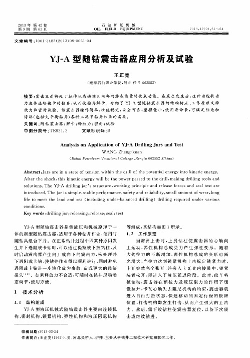
时启 动震击 器 产生 向上 或 向 下 的震 击 力 , 来 处 理 井
下 遇 阻或 卡钻 , 使钻井 作 业得 以顺 利进 行 , 同时避 免 遇 阻 或卡钻 进 一步 演 化 成 为 事故 , 造成 更 大 的经 济 损 失… 1 ] 。如 果释放 力 不合适 , 可 随 时在钻 井 现场 动 态调节, 使用 方 便 。
王 正 宽
( 渤海石油职业学 院, 河北 任丘 0 6 2 5 5 2 )
摘要 : 震 击 器是 将 处 于拉 伸状 态的钻具 内部 的 潜在 能量转 化成 动 能 。在震 击发 生后 , 这种 动 能将动
力 波传递 给被 卡 的钻具 , 从 而使钻 具 解卡 。介 绍 了 Y J — A 型 随钻 震 击器 的 结构特 点 、 工 作 原 理 及 释
( Bo h ai Pe t r o l e u m Vo c at i o nal Co l l e ge, Re n qi u 06 25 52, Chi n a)
Ab s t r a c t : J a r s a r e i n a s t a t e o f t e n s i o n wi t h i n t h e d r i l l o f t h e p o t e n t i a l e n e r g y i n t o k i n e t i c e n e r g y .
中 图分 类号 : TE 9 2 1 . 2
文献 标识 码 : B
An a l y s i s o n App l i c a t i o n o f YJ — A Dr i l l i n g J a r s a nd Te s t
W A N G Zhe n g— kua n
QY-A全液压随钻震击器使用说明书(中文)
9. 订货须知...................................................................................................................................................... 15
4-1. 下井前的准备 .................................................................................................................................... 3 4-2. 在钻柱组合中的位置.......................................................................................................................... 4 4-3. 钻柱摩擦力 ........................................................................................................................................ 4 4-4. 开泵力 ............................................................................................................................................... 4 4-5. 上击 ................................................................................................................................................... 5 4-6. 下击 ................................................................................................................................................... 6 4-7. 释放力调节方法................................................................................................................................. 6 5. 维修和保养 .................................................................................................................................................... 7 5-1. 准备 ................................................................................................................................................... 7 5-2. 拆卸步骤............................................................................................................................................ 8 5-3. 装配步骤............................................................................................................................................ 9 5-4. 限位块的修配 .................................................................................................................................. 11 6. 充油与试验 .................................................................................................................................................. 12 6-1. 充油 ................................................................................................................................................. 12 6-2. 释放力试验 ...................................................................................................................................... 13 6-3. 密封试验.......................................................................................................................................... 13 7. 常见问题及解决方法.................................................................................................................................... 14 8. 易损件及专用工具 ....................................................................................................................................... 15
JZ型机械式随钻震击器

2、技术参数
型号 外径 内径 mm mm 接头螺纹 API 最大抗拉负荷 最大工作扭矩 MN k N·m 开泵面积 cm2 上击行程 mm 下击行程 mm 总长(锁紧位置) mm
JZ95 JZ121 JZ159Ⅲ JZ165 JZ178 JZ203
95
28
27/8REG NC38 NC46 NC50 NC50 65/8REG
jz型机械式随钻震击器机械表钻数男机械魔法背击苏州天钻机械神圣震击宏震击监视器和保险箱震击器钻展点击率裂震钢钻法术作用于一体,采用全机械式的随钻 震击器。其上、下震击负荷范围比较广,可以在维修站或现场 根据需要进行调节。特殊的挠性接头可以有效地降低震击器本 体的挠应力,因此它是打直井、深井、复杂井和定向井的首选 随钻震击工具。
0.8 1.4 2.2 2.2 2.3 2.5
8 13 15 15 15 20
32 60 100 100 100 176
200 198 149 149 147.5 144.5
200 205 166 166 167.5 176.5
5800 6 343 6 517 6 517 6 570 7 244
121 51.4 159 57 165 57 178 57 203 71.4
05--液压-机械式随钻震击器

五、液压-机械式随钻震击器一、概述本节只介绍加拿大Wenzel “文策”公司的液压—机械一体式随钻震击器。
“文策”随钻震击器集上、下震击作用于一体,具有稳定的工作性能和强大的上、下震击力,可解除钻井作业过程中发生的井下遇阻、遇卡等事故,是定向井、深井钻进作业中优选推荐的震击工具。
二、型号表示方法规格系列及性能参数见表5-1,现有型号:8〞(7 3/4〞) 、6 1/4〞、4 3/4〞。
表5-1 规格系列及性能参数三、结构、工作原理 1、结构“文策”随钻震击器是机械—液压结构,上击机构为液缸、阻力阀,位于随钻下部;下击机构为卡瓦、碟簧,位于随钻上部 (如图5-1) 。
图5-1 “文策”随钻震击器2、工作原理上击下放钻柱使震击器完全关闭(处于锁紧位置),按从小到大吨位顺序上提钻柱,迫使碟簧、液缸储能、延时,当心轴上行到解除阻力状态,钻柱中贮存的弹性势能转换成向上的动能,产生上击。
重复上述过程,可使工具再次上击。
下击上下活动钻柱使震击器完全关闭(处于锁紧位置),下放钻柱,使碟簧压缩贮能,当震击器所受压力大于震击器预定下击解锁力时,卡瓦从心轴上滑出,解除锁紧状态,产生下击。
重复上述过程,可使工具再次下击。
四、使用与操作1、下井前的检查随钻震击器下井前,应对照《工具跟踪卡》进行检查,确认合格后方可进行下步工作。
2、连接随钻震击器在钻柱中连接位置的确定(1)随钻震击器应连接在钻柱中和点附近,推荐的钻柱组合如下:2根钻铤(外径不小于震击器外径)+“文策”随钻震击器(心轴端向上)+加长短节+2根钻铤(外径不大于震击器外径)。
(2)在容易出现压差卡钻的地层,震击器应安装在井下钻柱组合相对靠上的位置,以防止震击器以上钻具发生卡钻。
(3)在容易出现机械卡钻的区域,震击器在井底钻柱组合中的安装位置可以相对靠下,以提高震击器的工作能力。
(4)震击器不能直接连接在扶正器上,至少在扶正器上有两根钻铤。
震击器的连接应该避开钻柱中的变扣接头,应位于变扣接头上、下至少两个单根。
QY-A全液压随钻震击器使用说明书(英文)
QY-A DRILLING JAR OPERATION MANUALBEIJING PETROLEUM MACHINERY CO.SEP 2010ForewordThis new kind of drilling jar, including its structure, principle and application is introduced in this manual. After the drilling jar being used and repaired by customers, its reliability and performance may have some changes. These changes depend on the application conditions and maintenance level.Because of the continuous improvements on the products, some details in the manual may not be same as in actual operation. These differences don’t affect the understanding of the product's structure, the performance and the application by customers. If having any questions, please contact us.The service-life of the drilling jar and operation effects are related with not only designing and manufacturing but also properly operating of customers.We would like to supply customers with high quality products in compliance with specification of the quality assurance system of ISO9001, and also hope that the operators can carefully read the manual to insure the performance of products and successfully achieve the expectant drilling operations.The drilling jar and the information in this manual may not be suitable in some special applications. The operator should make right judgment on the selection and the application of the drilling jars.As the continuous improvements on the drilling technology, the customers will have new requirements on the application. We will be very happy to continuously improve our products to meet your special requirements.Welcome to contact us by the following methods!BPM Beijing Petroleum Machinery Co.Address: No. 41 Zhixin Road, Haidian District, Beijing 100083, China86-10-62098867Fax: 86-10-62311837,Phone: 86-10-83597657(Sale)86-10-83597659(Technical)Homepage: E-mail: bpm.tech@Content (1)1. Description2. Model Illustration (1)3. Principle (1)4. Application Notice (3)in the BHA (3)4.2 Position4.3 Frictionthe drill string (4)of (4)4.4 Pump-openForce4.5 Jarring up (5)4.6 Jarring down (5)4.7 Methods of the adjusting of the release force (5) (6)5. Maintenance5.1 Preparation (6)5.2 Disassembling Procedure (7)Procedure (8)5.3 Assembling5.4 Repair & Coordinate the limiter (9)6. Test & Oil Filling (10)Filling (10)6.1 Oil6.2 Release force test (10)6.3 Sealing Test (11)7. Trouble & Solutions (11)8. Damageable Components (12)9. Notices for Ordering (12)1. DescriptionQY-A hydraulic drilling jar is a new kind of drilling jar which is suitable for a wide range of drilling operations. This drilling jar overcomes the defects of pure mechanical drilling jar or pure hydraulic drilling jar and combines with merits of them. Mechanical lock and hydraulic delay works together in the process of jarring up and jarring down.The QY-A drilling jar has following features:1) It can avoid unexpected strike effectively.2) No need any safety clamps or other special actions on the drilling or tripping.3) Free position in the BHA (in tension, neutral or compression).4) Mechanical lock unit is not affected by the torque.5) The release force of jarring up or down can be adjusted on the drilling platform. Its operation isvery simple, exact and stable.6) Hydraulic delay allows the driller to adjust the jarring up or down force.7) Enclosed oil chambers increase seals and components life.8) Suitable to work in high temperature situation.9) It is an ideal tool for controlled directional well and horizontal well.2. Model Illustration3. PrincipleThe structure of QY-A drilling jar is shown in Figure 1, which be made up of housings, mandrels, valve unit, spring unit and lock unit and so on.QY-A is a new kind of drilling jar which combines the mechanical with hydraulic structures. The hook lifts the drill strings to make the mandrel move up, the spring unit takes place elastic deformation at the pull or push. The more energy from the hook, the spring unit does the greater deformation. When the deformation reaches high-point, the trip sleeve opens immediately and engages with friction sleeve, and then the jar enters the hydraulic-delay state. The cable hoist is baked at the same time. The drilling jar isCode (Drilling jar with adjustable release force)pulled slowly in the effect of pull force and hydraulic resistance force. The jar enters striking state after these series actions. The trip mandrel moves to the limit position quickly along its fixed path. After striking, set down the drill strings to make the jar reset for drilling or striking.Figure 1 the Structure of QY-A Drilling Jar Friction SleeveSpline MandrelStabilizerSpline Housing Upper Valve Housing Hydraulic Cylinder Lower Valve HousinSealBack NutSafe RingUpperValveMandrelValve UnitLower Valve MandrelUpper control HousingMiddle Control HousinConnect UnitLower HousingBottomTripLimiterLock ScrewUpper Adjusting SleeveSpring UnitPistonOil PlugLower Adjusting SleeveExtendedTrip SleeveLocated SleeveAdjusting SleeveWhen jarring down is needed, push the drilling jar until the pressure exceeds the release force. The lock unit opens soon and the trip sleeve opens immediately and engages with friction sleeve, and then the jar enters the hydraulic-delay state. The cable hoist is baked at the same time. The drilling jar is pulled slowly in the effect of pull force and hydraulic resistance force. The jar enters striking state after these seriesactions. The trip mandrel moves to limit position quickly along its fixed path producing huge jarring down force. The lock unit locked again when the drilling string is pulled, then the drilling or striking can be continued.The release force on the drill strings can be adjusted by the adjusting sleeve and the connect unit. In the adjustment process, first disassemble the cover screw, and then turn the adjusting sleeve by the spanner or the screwdriver alongside the thread to make an axial displacement and thus adjust the release force.4. Application Notice4.1 Prepare before down-hole operationThe drilling jar in the down-hole operation must be new or repaired after being used. The continuous working period of a new drilling jar for a single trip may not exceed more than 500 hours, not more than 300 hours for a repaired one. In high temperature or under the condition of acrid medium in the well fluid, it is not suitable to work for a long time. To avoid failure, the drilling jar should be repaired after being used in down hole, or else it is forbidden to use again.4.2 Position in the BHAJarring up or down of the hydraulic drilling jar is a whole section, and this can be subjected to a slightly pull force or push. In order to avoid free vibration of drill string affecting the jar’s life, it is important to avoid putting the jar on a neutral point of drill string. An ideal position is below the neutral point of the drill string, and this can make the pressing force on the drill string equal to the pump-open force.The drilling jar must be placed at the right position in the BHA to guarantee its proper effects and avoid some accidents. The jar's proper position is determined to the well conditions. Generally, the lower position, the better effect. In addition, the large pull or push force could result in unexpected strike.(1) Disposal on the lower location of the assembly (be pushed).The drilling jar is located above one drill collar at least where the collar is above the top centralizer.The drill collars located between a centralizer and a drilling jar can make the jar safer. For example, the drilling jar can not be stuck and dislodged by the rock cutting deposit. If a shock absorber locates in the drill strings, the drilling jar should be above it.(2) Disposal on the upper location of the assembly (be pulled).If it is predicated that the drill collars occur drill pipe stuck caused by pressure difference, the jar should be assembled on the position which is high enough in the drilling strings and always above the stuck point. But the disadvantage is that the distance between the jar and the stuck point would be too long and it could affect the jarring effect if the bit or the centralizers are stuck.4.3 Friction of the drill stringFriction is a kind of force generated between the drilling tool and borehole wall. Its empirical value is 50 kN ~200 kN. The friction is relevant with the BHA, mud condition and well bore structure. The force should be determined by the work site.During practical operation, the operators should exactly estimate the friction of the drill string.4.4 Pump-open ForcePump-open force is a kind of force exerting on the jar caused by the mud pressure in the drill strings in normal running. If the mud pressure is high enough, it will pull the jar open. Thus, the hook weight should deduce the pump-open force in the jarring up or down when calculates the force.The pump-open force is proportional to the pressure in the drill string and the piston equivalent area. So the pump-open force can be work out following:Pump-open force (kN) = piston area (mm2) -pumping pressure (MPa) ×10-3The piston equivalent area is related to the structure of the drilling jar. The pump-open force of QY-A drilling jar lists on the below table 1.Table 1 the Pump-open Force of QY-A Drilling Jar (kN)QY203AQY229AModel QY121A QY159A QY165A QY178APiston Area/mm24806 7835 7835 10722 13823 18850Pump Pressure/MPa971327555557 341381881077810 487819415026411014 6711027637721420 961571574.5 Jarring upWhen the jarring up is needed, lifting the drill strings to make the pull force reach the standardrelease force of the jar, an up-strike force would be produced. Pushing the drilling tools to make the jarreturn the reset position, the locking unit relocks again. Repeating the above steps will achieve the effectof continuous up strike. In jarring up, the hook load is calculated as follows:Hook load = hang weight on the drill string above the jar + frictional force on the drill strings +standard release force - pump-open force4.6 Jarring downWhen the jarring down is needed, lowering down the string to make the press force reach thestandard release force of the jar, a down-strike force would be produced. Pulling the drilling tools tomake the jar return the reset position, the locking unit relocks again. Repeating the above steps willachieve the effect of continuous down strike. In down strike, the hook load is calculated as follows: Hook load = hang weight on the drill string above the jar - standard release force- Frictional forceon the drill strings - pump-open force4.7 Methods of the adjusting of the release forceWe can make use of the adjusting sleeve on cover screw of the drilling jar by the spanner or thescrewdriver to adjust the release force. The upper adjusting sleeve is used for adjusting the up-strikerelease force, and the lower adjusting sleeve for the down-strike release force.There are 25 adjusting grooves on the circumference of the nut that is made letters on the bottomof the grooves. It marks "+" and "-" beside the cover hole, which represents the increase or the decreasedirection of the release force. Letters near the cover hole represent the position of the standard releaseTable 2 the adjusting value every grooveforce on ex-works or on the maintenance.During the adjusting (increasing or decreasing), when the upper or the lower adjusting sleeve can’t be adjusted, it reaches limited position, i.e. maximum or minimum release force.Notice: During the adjusting (increasing or decreasing), lock screw is forbidden to be disassembled or loosen.The every groove can adjust the release force as table 2. On the actual application, adjust the upper or the lower adjusting sleeve every time for one or a number of limiting grooves and record theletter till it reaches the proper tons. It canachieve the adjustment of the force5. MaintenanceOnce the new drilling jar continuously works in the down hole more than 500 hours or 300 hours for the repaired one, it must be checked and disassembled. It is suggested that the drilling jar should be abandoned after it has worked for 1500 hours or 2 years.Before disassembly, the drilling jar should be tested and the data should be recorded.5.1 Preparation①Break-out / Make-up equipment and proper tools, including pipe wrench, chain wrench, nylon slinging belt, etc. is needed.②Sealing and wearing parts. Model Adjusting Value (kN) QY121A 25QY159A 30 QY165A 30 QY178A 40 QY203A 50QY229A 60╋ ╋Page 7 of 12③Lubricants, molybdenum disulfide(MoS 2) lubricant oil and L-HM 32 hydraulic oil. ④Technical files and service drawings of the drilling jar. 5.2 Disassembling ProcedureIn disassembly, it is forbidden to damage sealing surfaces or outer surface of the thin wall housing. Before the disassembly, the drilling jar must be in reset position.The housing threads of the drilling jar are cone screw threads and painted Y680 bounded agent. Locally heat the connection place of all cone screw thread to make bounded agent invalid for dismantling. The surface temperature after heating cannot go beyond 250 and it is noticed that the ℃heating area cannot extend to protect seal parts from damage.(1) Before the disassembly, confirm the drilling jar in the reset (latched) position. Then prepare the oilcontainer, disassemble the oil plug by a spanner, empty the hydraulic oil in the cavity and disassemble the cover screws and lock screws. (2) Disassemble the bottom sub.(3) Disassemble the piston with the special tool and valve unit.(4) Disassemble the lower housing. After loosen the threads, hoist and dislodge it horizontally by thehanging belt. Take notice of the coaxial with upper control housing and the rest.(5) Disassemble the connect unit, turn out the lower adjusting sleeve. (Record the position of thembefore turning out.)(6) Disassemble the middle control housing. The disassembly way is same as the lower housing. Takeout the spring unit, separating sleeve, lining, friction sleeve and adjusting ring in the middle housing in sequence.(7) Disassemble the trip sleeve. First disassemble the extended mandrel, seize up the bottom end ofthe trip sleeve by the hanging belt and pulling it out by assembling test unit. Take out the separating sleeve and the spring unit on the mandrel in sequence.(8) Disassemble the upper control housing. The way is the same as the lower control housing. And turnout the lower adjusting sleeve. (Record the position of them before turning out.) (9) Disassemble the lower valve housing.(10) Disassemble the lower valve mandrel and the valve unit.(11) Disassemble the upper valve housing, as the way of the lower valve housing.(12) Disassemble the upper valve mandrel, the valve unit and the back nut.(13) Disassemble the spline housing, stabilizer and the spline mandrel.(14) Disassemble all the seal components.(15) Flush all the components by cleaning equipment. Check the injury status of the components. Afterchecking, the housings, the spline mandrel, the trip mandrel, friction sleeve, trip sleeve, spring unit, adjusting sleeve and the trip mandrel coupling should be detected. The displacements are replaced according to the destructive status.(16) After taking out the drilling jar from the well, all the seal components should be replaced every time.5.3 Assembling Procedure(1) Pick out invalid parts, substitute new available components and prepare a set of seal and the toolsfor oil injection.(2) Clip the stabilizer with the chain clamp of the assembling unit. First, assemble the wiper ring, sealring and supporting ring into the stabilizer. Then hoist the spline mandrel horizontally, and carefully boot the spline into it and pay attention not to damage the spline body and seal parts.(3) Insert the spline mandrel into the stabilizer(the bare length of the spline mandrel is about 310mm )(4) Assemble the orienting sleeve and seal components into the spline housing.(5) Assemble the clamp ring. Turn the back nut into the spline mandrel and install the spline mandreland the upper valve mandrel. Tighten the back nut and the upper valve mandrel.(6) Assemble the supporting ring to the upper valve mandrel; tighten it with the spline mandrel. Installthe seal part on the mandrel. Assemble the spline housing and upper valve housing together.(7) Pull the spline mandrel to the max trip and install the valve unit.(8) Assemble the seal parts and locker screw on the lower valve mandrel.(9) Assemble the hydraulic cylinder and upper valve housing.(10) Assemble the seal part on the lower valve housing, tighten the hydraulic cylinder and lower valvehousing together.(11) Assemble the seal part on the lower valve mandrel and tighten it with the upper valve mandrel andtrip mandrel (the special tool is needed).(12) Screw the upper adjusting sleeve into the upper control housing. When the distance between theend surface of the adjusting sleeve and that of the housing is “X” (the up strike is 0), the value of Page 8 of 12Page 9 of 12“X” is different from the model of QY-A drilling jar, check it on table 3, install the upper control housing.Table3 the distance between the end surface of adjusting sleeve and that of housingModelDistanceQY121A QY159A QY165A QY178A QY203A QY229AX 5 8.4 8.4 11.5 11.2 11.8 Y 4.7 8.4 8.4 11.8 11.6 12(13) Install the extended mandrel and the trip mandrel.(14) Assemble the spring unit and the separating sleeve on the mandrel in the order. Plug the trip sleeveinto the trip mandrel to make it into the groove, i.e. the reset position.(15) Assemble the bushing, adjusting ring, locating bush, and trip sleeve into the middle housing. Installthe middle housing.(16) Screw the lower adjusting sleeve into the connect unit and ensure that the distance between thehead face of the adjusting sleeve and that of the housing is Y (the down strike is 0), the value of “Y” is different from the model of QY-A drilling jar, check it on table 3, then install the connect unit. (17) Assemble the seal part on the piston and tighten it with the extend mandrel. (18) Assemble the lower control housing with the rest. (19) Install the top sub and assembling is accomplished.All the threads should be screwed down according to the make-up torque on table 4.Table 4 the make-up torque list of the threads (kN·m)ModelthreadsQY121A QY159/165A QY178A QY203A QY229A torque feed torquefeed torque feed torque feed torque feed housings 14 MoS 2 25 Y68035 Y68045 Y680 60 Y680mandrels 5 MoS 2 8 MoS 28 MoS 211 MoS 2 11 MoS 2Mandrel/piston 4 MoS 2 7MoS 28MoS 29MoS 211MoS 25.4 Repair & Coordinate the limiterIf the release force can not meet the requirement after long time using, repairing and coordinating the limiter is a good solution. If the custom wants to ascend the max release force, pare the end face nearing the adjusting sleeve. The length calculates as this formula:Page 10 of 12L=fptΔ25 L: The pared length, mm.p: The adjusting sleeve’ screw-pitch ,check it on table 5, mm.t: Difference between the max release force required on table 1and fact force, kN. Δf: Increase or decrease force dialing every groove of the upper/lower sleeve, kN.Table 5 the adjusting sleeve’ screw-pitch (mm)Model QY121A QY159A QY165A QY178A QY203A QY229Ap 4.5 4.5 4.5 4.23 4.5 6.356.Test & Oil Filling6.1 Oil FillingWhen the drilling jar has been assembled, it must be filled the oil into the cavity before the release force test.The liquid in the drilling jar is L-HM32 hydraulic oil. During oil filling, the drilling jar is required in the reset position.First, inject the barrel of the pump with the filtrated L-HM32 hydraulic oil. Before injection, lift upward the hole on the jar and then incline it by the traveling hoist at the angle of more than 30 degrees, in addition the large end of the mandrel is upward.The following is the connecting way between the oil pump and the hole on the jar. The hosepipe on the oil injection pump is connected with the bottom housing; one end of the return line connects to the hole on the spline body, and the other end inserts into the tubing. After connecting, the pump starts up. Wait till the air bubbles in the return line disappear for a long time so that all the remnant air is discharged, disassemble the pipe, assemble the pipe plug, and then put down the jar in horizontal position, disassemble the feed pipe, and finally install the pipe plug on the bottom housing, completing oil filling.6.2 Release force testThe reassembled drilling jars must come up to the standard in the release force test and seal test before used.After oiling the just-assembled drilling jar, test it’s jarring up and jarring down force on the push-pullBefore the test, it is suggested to locate the limiter as pre-disassembled. Please reference”6.4 repair & coordinate limiter” if you want to adjust the max release force in the adjustable extent of the limiter.After setting up the release force, record the letter locating near the setting nut vessel, and print it on the labeled vessel nearing adjustable aperture(print it behind all the letters ),then assemble limit nut and adjustable nut.The drilling jar must be reset after having been tested.6.3 Sealing TestThe nozzle is plugged by special pressure test connection. One end of the high-pressure hose is connected with the water inlet on the sub, the other end with the outlet on the electric pump. Make the air vent upward and disassemble the plug on the vent.Start up the pump and inject water into the jar. When the water fills up the jar and overflows from the air vent, stop the pump and install the core vent. After the above steps, start the pump again. When the pump pressure is up to 30MPa, stop it and retain the pressure for 5 minutes. If the pressure drops less than 0.5MPa, it represents the pressure test is ok. Disassemble the subs on the two ends. After drying the hole, paint the sealing grease and assemble the screw protector.7. Trouble & SolutionsBecause of the simple structure and the reliability of the mechanical QY-A drilling jar, a new jar or a jar after a normal repair won't have trouble. The trouble shooting during the application is as follows:a. the upper/lower adjusting sleeve can not be adjusted(1) If the upper/lower adjusting sleeve can adjust only toward one way, it indicates that the drilling jar has already been the max or min release force position. It is normal.(2) The drilling jar is not reset .Please pull or push it aptly. Push make jar reset when the jar has been up jarring or pull after down jarring.(3) The tool is too small to adjust the sleeve, please change a bigger one.b. No strike after the drill string lifted up(1) The jar is already at up-strike position. More drill springs would be lowered down to make the drilling jar be pushed, and then lift the strings up.(2) If the down-strike release force on the drilling jar is adjusted too low or too high, lift the jar outPage 11 of 12(3) If the lock unit of the jar is stuck and lodged, lift up the jar and repair it.c. No strike after the drill string lowered down(1) The jar is already at down-strike position, pull jar and lower down the drill string again.(2) If the down-strike release force on the drilling jar is adjusted too low or too high, lift the jar out to modulate.(3) After the drilling jar strikes for many times, and if the locking unit on the jar is stuck and lodged, lift the jar up and repair it.d. Vibration during normal drilling (unexpected strike)(1) If the release force on the drilling jar is adjusted too low, the vibration on the drill string will cause unexpected strike. Try to decrease the vibration on the string or increase the release force on the drilling jar.(2) If the jar in BHA locates at an inappropriate position, it will undertake so much larger pull force or compress force in normal drilling operation. If unexpected striking down, try to decrease the drilling pressure or increase the position of the drilling jar on the drilling assembly; otherwise, if unexpected striking up, try to increase the drilling pressure or decrease the position.8. Damageable ComponentsAfter the jar has worked in the well one time, all the sealing parts must be replaced.Check the stress-containing and frictional parts. If having any damage, replace it. Damageable components and special tools are shown in the following additional table.9. Notices for Ordering(1) Model of the products should be written clearly and completely.(2) If having special requirements on the connect threads, please give us a detailed information when ordering. If no details, we will supply our standard supplies.(3) Name, order number and quantity should be written clearly if ordering spare parts and tools.Page 12 of 12Additional Table 1:Damageable Components of QY121A Drilling JarSerial Number Items Order Number Quantity RemarkMandrel 9324610001 11 SplineSleeve 9314620004 22 SealHousing 9324610002 13 SplineNut 9314620008 14 Back5 Up Valve Mandrel 9324610004 16 Valve Unit 9314620200 2 complete setMandrel 9324610006 1Valve7 DownMandrel 9324610009 18 Trip9 Limiter 9314631007 2Screw 9314620010 210 LockScrew 9314620011 211 CoverUnit 9314620100 2 completeset12 SpringSleeve 9314630012 213 LocatedSleeve 9314630014 114 FrictionSleeve 9314630013 115 Trip16 TopSub 9324611010 117 Seal Components 9324610900 1 complete setSpecial Tools of QY159A Drilling JarSerial Number Items Order Number Remark1 Special Spanner 9316220810 Install valve mandrel piston2 Screw Plug 9316220820 Install trip sleeve3 Screw Block 9316220830 lead while trip installing4 Axle Pin 9316220840 Install valve coreIAdditional Table 1:Damageable Components of QY159A Drilling JarSerial Number Items Order Number Quantity RemarkMandrel 9326211001 11 SplineSleeve 9316220005 22 LeadHousing 9326210002 13 SplineNut 9316220009 14 Back5 Up Valve Mandrel 9326210004 16 Valve Unit 9316220200 2 complete setMandrel 9326210006 1Valve7 DownMandrel 9326210009 18 Trip9 Limiter 9316220014 2Screw 9316231002 210 LockScrew 9316230008 211 CoverUnit 9316220100 2 completeset12 SpringSleeve 9316220018 213 LocatedSleeve 9316220020 114 FrictionSleeve 9316220021 115 Trip16 TopSub 9326211011 117 Seal Components 9326210900 1 complete setSpecial Tools of QY159A Drilling JarSerial Number Items Order Number Remark1 Special Spanner 9316220810 Install valve mandrel piston2 Screw Plug 9316220820 Install trip sleeve3 Screw Block 9316220830 lead while trip installing4 Axle Pin 9316220840 Install valve corePage II of 12Additional Table 1:Damageable Components of QY159A Drilling JarSerial Number Items Order Number Quantity RemarkMandrel 9326211001 11 SplineSleeve 9316220005 22 LeadHousing 9326210002 13 SplineNut 9316220009 14 Back5 Up Valve Mandrel 9326210004 16 Valve Unit 9316220200 2 complete setMandrel 9326210006 1Valve7 DownMandrel 9326210009 18 Trip9 Limiter 9316220014 2Screw 9316231002 210 LockScrew 9316230008 211 CoverUnit 9316220100 2 completeset12 SpringSleeve 9316220018 213 LocatedSleeve 9316220020 114 FrictionSleeve 9316220021 115 Trip16 LowerHousing 9324610010 117 Seal Components 9324610900 1 complete setSpecial Tools of QY121A Drilling JarSerial Number Items Order Number Remark1 Special Spanner 9314620810 Install valve mandrel and piston2 Screw Plug 9314630810 Install trip sleeve3 Axle Pin 9316220840 Install valve coreIII。
ZsxJ型随钻震击器

Zs J x 型随钻震击器由ZSJ型上击器和ZXJ型下击器两个独
立的震击机械式。使用时将随钻震击器 连接在钻具中和点附近,当钻井作业过程中发生井下遇阻、
遇卡等事故时,可随时启动震击器进行上击或下击解卡。它
是打定向井、复杂井、斜井必不可少的随钻震击工具。
s
Z J70 x 178 70 51/2FH 2.3 15 550 346 550 182 180 6 359 5 457
s
Z J76 x 197 71.4
s
Z J80 203 71.4
65/8REG 65/8REG 2.5 18 750 370 600 181 180 6 670 5 249 2.5 20 750 370 600 181 180 6 597 5 249
s x
Z J56 x 146 57 41/2FH 2.0 15 450 330 400 182 180 5 738 5 000
s
Z J62Ⅱ x 159 57 NC46 2.2 15 550 346 550 182 180 6 738 5 371
s
Z J64 x 165 57 NC50 2.2 15 550 346 550 182 180 6 736 5 457
ZSJ型上击器
ZXJ型下击器
2、ZXJ型随钻下击器技术参数
型号 外径 内径 接头螺纹 最大抗拉负荷 最大工作扭矩 最大上击吨位 最大上击行程 最大下击吨位 最大下击行程 最大工作温度 上击器总长 下击器总长 mm mm API MN kN· m kN mm kN mm ℃ mm mm
s x
Z J46 121 51 NC38 1.4 13 270 305 250 182 180 6 391 5 125
Griffith 震击器
Griffith 液压/机械随钻震击器使用手册1.1概述随钻震击器是连接在井下钻具组合中的一种工具,在钻井卡钻事故中能立即被用来对钻柱中的卡住部分产生震击作用,以达到解卡的目的。
随钻震击器一般分两种:一种是机械式;一种是液压式。
它们各有优缺点。
机械式随钻震击器的优点是:●在不需要震击时总是处在锁定位置;●在井下钻具组合的位置所受的限制较少;●在起下钻作业时不会发生意外震击;●起下钻作业时无特殊步骤要求;●钻台上不需要“安全卡瓦”和特殊处理步骤;●在正常钻进作业期间的磨损最小。
机械式随钻震击器的缺点为:●震击器在井下的震击力不可以变化;●当震击器锁定设置值被克服后会即刻震击,这种震击器有可能损坏提升设备(Hoisting Equipment);●旋转类型受扭矩影响(Rofary type affected by torque)。
液压震击器的优点是;●在井下的震击力可通过改变超载拉力(amcunt of overpull)来改变;●因有时间延迟,从而有时间在钻台带上刹车,以保护提升设备;液压震击器的缺点为:●起下钻作业或单独吊震击器时有可能意外震击;●在BHA钻具组合中的位置受限制,必须在钻具组合中总是处于张力状态;●在起下钻作业时有特殊步骤要求;●在钻台上操作时需要安全卡瓦(Safety collar);●在钻进时有轴向活动,这样加快了磨损速度;●在连续震击后,有容易出故障的名声。
1.2 Griffith 液压/机械随钻震击器的特点Griffith 液压/机械随钻震击器的开发,结合了液压和机械震击器的特点,克服了这两种震击器的固有缺点。
它的独特设计把液压延迟释放与机械锁定机理混合在一个相对较短的双作用随钻震击器上,使这种井下工具可提供几种相对传统液压或机械震击器的优点:●液压延迟时间允许操作者可施加不同的超载拉力(overpull),同时可应用刹车系统(draw-works drum brake)。
机械随钻震击器
(一)、Z SJ型随钻震击器X1. 概述J型随钻震击器是连接在钻具中,随钻具进行钻井作业的井下工具。
若在正常钻井Z SX过程中因种种原因井下发生遇阻、遇卡或卡钻时,可以启动震击器进行上击或下击,及时解除井下卡钻事故。
随钻上击器和随钻下击器是配套使用的,也可因井下作业需要,单独下井使用。
它是打定向井、深井必不可少的工具。
使用随钻震击器具有如下优点:1.1 随钻密封性能好,随钻具使用周期500小时左右,超过了一支钻头的使用时间,所以不会因随钻本身不能使用的原因而起钻影响纯钻时间。
1.2 可以随震击需要产生上击或下击。
1.3 解除井下卡钻事故迅速及时,而且震击效果好,这就给正常钻井作业带来了无比的优越性,不仅减少了事故,而且减少了因事故而带来的无法估计的经济损失。
1.4 使用时操作简单方便,而且便于记忆,上提即产生上击力,下放就产生下击力,因而司钻操作时不会搞错。
2. ZSJ型随钻上击器结构随钻上击器,由外筒部分、心轴部分、活塞部分和各部位的密封件组成。
外筒部分:刮子体、心轴体(左旋螺纹)、花键体、压力体、冲管体。
心轴部分:心轴、延长心轴、冲管。
活塞部分(锥体组件):锥体、旁通体、密封体、密封体油封。
3. ZSJ型随钻上击器工作原理3.1 上击器的回位随钻上击器采用液压工作原理实现上击,机构为锥形活塞结构,它是由锥体,旁通体,密封体和油封四件组成。
在钻井中,心轴呈拉开状态。
震击时,需先下放钻柱使心轴向下移动,此时锥体处上、下油腔的通道启开,油流畅通,上击器处于回位状态(上击器回位之力不得超过下击器下击吨位),直到心轴台肩碰到刮子体为止,产品完全关闭。
3.2 贮能过程上击器心轴向上运动时(即司钻上提钻具),密封体上端面与锥体下端面贴合,上、下油腔关闭,此时液压油只能从锥体底面的泄油槽通过,形成阻力,液压油受压,钻柱受拉伸产生弹性伸长,同时钻具贮存了能量,钻具继续伸长,储能相应增加。
3.3 释放震击过程当锥体活塞到达压力体的卸荷腔的瞬时,受压的液压油以极高速度沿锥体外表面向下腔流动,高压油腔突然减压,受拉的钻柱在弹性作用下以极高的速度向上运动,直到延长心轴上端面碰击到花键体花键下台肩面上,这就产生了猛烈的向上震击。
石油钻井行业井下事故处理专用工具使用介绍(特别详细)
⽯油钻井⾏业井下事故处理专⽤⼯具使⽤介绍(特别详细)⽬录第⼀章概述⼀、常见原因五、打捞作业第四章井下动⼒钻具⼀、LZ型螺杆钻具⼆、WLZ型涡轮钻具第五章抓卡打捞⼯具(⼀)、AJ(⼆)、H型和J(⼀)、LT—T型可退式打捞筒(⼆)、KJ(三)、DLT—T型可退式倒扣捞筒(四)、KLT型卡⽡打捞筒(五)、WLY型弯鱼头打捞筒(六)、CLT-TA可退式抽油杆打捞筒(七)、CJL型抽油杆接箍打捞筒(⼀)、LM型可退式打捞⽭(⼆)、LM-T(DS)(三)、SLM型双级卡⽡打捞⽭(四)、ZDM(五)、TLM(六)、DLM(七)、YLM(⼋)、GLM(九)、BLM(⼗)、DLM—T四、打捞篮(⼀)、LL(⼆)、QLL(三)、ZL(四)、BZ型⼀把抓五、DLQ型多功能打捞器六、LB七、GGZ型GMZ型⾼强度公母锥⼋、CL型强磁打捞器九、FCL型反循环强磁打捞器第六章震击器(⼀)、YSJ(⼆)、CSJ(三)、JS⼆、YJQ(⼀)、KXJ(⼆)、BXJ(三)、DJJ(⼀)、Z S(⼆)、JZ 型机械(三)、YSZ(四)、JSZ型整体机械式随钻震击器(五)、JYQ型机械、液压随钻震击器第七章套铣割⼑类⼀、内割⼑(⼀)、NG型机械式内割⼑(⼆)、ND—S型⽔⼒式内割⼑(三)、AND—S型⽔⼒式内割⼑(⼀)、WDJ(⼆)、WD-S三、套铣⼯具(⼀)、TXG(⼆)、TX—D(三)、TX—F型防掉套铣⼯具(四)、TDX型套管段铣器(五)、TKC(⼀)、PMX型平底磨鞋(⼆)、XZ型铣锥(三)、GMX型⾼效领眼磨铣器五、SQJ型⽔⼒切割接头第⼋章随钻⼯具(⼀)、YFQ型液压变径扶正器(⼆)、KFQ型可变径扶正器(⼀)、YJA(⼆)、YJB(三)、SJ(四)、DHJ型机械液压减震器四、KMJ型抗磨接头五、TLQ型液⼒推⼒器六、SJQ型双⾏程⽔⼒加压器七、XFQ型悬浮器⼋、HYQ型三滚轮划眼器九、KYQ型扩眼器⼗、JKQ⼗⼀、ZW型钻井弯接头⼗⼆、WJT⼗三、DJT型定向接头⼗四、DKJ型倒扣接头⼗五、DZ型整体式短钻杆⼗六、DZT型短钻铤第九章内防喷⼯具⼀、SXS⽅钻杆旋塞X⼆、SJF型双功能箭形回压阀三、JF型箭形回压阀四、FF型钻具浮阀五、HY型投掷式回压阀第⼗章采油⼯具⼀、AF型安全阀⼆、Y型封隔器三、SGF型过电缆封隔器四、QS型桥塞五、TQ型抽油杆脱接器第⼗⼀章地⾯拆装试验装置⼀、YXD20全液压拆装架⼆、S150液压试验架三、LYZ液控拉压装置四、CXT1400五、S-100六、JZP第⼗⼆章其它⼯具介绍⼀、TSDJ型提升短节⼆、ST三、GGQ型套管刮削器四、SZZ型双作⽤套管整形器五、LZQ型梨形整形器六、QM型铅模七、JD⼋、FX-PQ型FG-PQ九、YWX178液压尾管悬挂器⼗、JKT打捞⼯艺是以丰富的现场实践经验为基础⽽逐渐发展形成的⼀门应⽤学科,没有固定的模式可遵循。
钻井事故及处理工具
钻井事故及处理工具(中英文对照)钻井事故及处理工具drilling accidents and treatments钻井井下事故downhole drilling accident钻井作业在井内发生的各种事故的总称。
1. 卡钻pipe sticking凡钻柱在井内不能上提、下放或转动叫做卡钻。
2. 机械卡钻mechanical sticking除压差卡钻之外的卡钻统称为机械卡钻。
3. 泥包卡钻bailing-up sticking钻人泥页岩地层不能及时清除井底岩屑,钻井液与岩屑混合物紧紧包住钻头或其他井工具形成的卡钻。
4. 砂桥卡钻sand bridge sticking岩屑在井径变化处急聚堆积造成的卡钻。
5. 沉砂卡钻solids settling sticking岩屑在井底沉积造成的卡钻。
6. 键槽卡钻key seat sticking; key slot sticking钻井作业过程中,钻具在井壁形成的槽沟内被卡。
7. 垮塌卡钻sloughing hole sticking由于井壁坍塌埋住钻具而发生卡钻。
8. 压差卡钻differential pressure sticking钻井液的液柱压力大于地层孔隙压力使钻柱紧贴于井壁,发生的卡钻。
同义词:粘附卡钻9. 小井眼卡钻undergauge hole sticking当井眼直径小于使用钻头直径,在下钻时钻头压人该井段造成的卡钻。
10. 缩径卡钻formation swelling sticking, hole shrinking sti由各种因素引起井径缩小而造成的卡钻。
11. 顿钻卡钻drill string free-fall sticking由于顿钻后钻具弯曲造成的卡钻。
12. 落物卡钻junk sticking由于井内落物而造成的卡钻。
13. 水泥卡钻cement sticking在挤、注水泥作业中造成的卡钻。
14. 干钻卡钻dry drilling sticking在无钻井液到达钻头时钻进而发生的卡钻。
钻井行业专业英语-钻机设备电动钻机部件的中英文对照表
high speed centrifuge drilling machanicl repairing house
• 泥浆泵护罩
cover, transmission device
casing sealing grease drill tools screw thread grease
mat for rotary table shoulder pole
• 防溢管 • 起架大绳 • 钻头盒 • 堵塞器 • 扩孔方瓦 • 扩孔方瓦 • 吊卡 • 套管吊钳 • 套管吊卡 • 多片式卡瓦
towel feeding Rubber Pipe
palm rope steel wire
cylinder explosion-proof electromotor
• 钢丝钳 • 电笔 • 光咀钳 • 挡圈钳 • 小剪刀 • 管子割刀片 • 管子扳手 • 割咀 • 砂纸 • 电工刀
wire cutter electrical pen combination pliers block circle tong small scissors pipe cutter reamer
portable grinding wheel machine pressure indicator
double scale pressure multimeter acetylene reductor
oxygen reductor pressure meter general pressure meter
multi flashboard AC contact instrument explosion-proof press button belt pyrocondensation instrument insulation glove low pressure switch Pressure Meter Pressure Meter water/oil filter core
QY型全液压随钻震击器使用说明
QY型全液压随钻震击器一、概述QY型全液压随钻震击器是一种井下钻具被卡时的解卡工具,是一种上、下击一体式液压随钻震击器,当钻具被卡时,能够提供一个巨大的冲击力,可以进行上击或下击动作以达到解卡目的,及时恢复正常钻井作业。
QY型全液压随钻震击器在井下使用时,操作者可以在地面通过调整上提或下放钻具(无需对扭矩或外部调整),就能产生释放上击或者下击的冲击力,并且可以调整冲击力从很小到所需的最大冲击力。
工具操作简单、方便和可靠性高,可以广泛适用于钻井、取芯、打捞和修井等多种井下作业。
二、工作原理上击工作原理:工作是通过上提钻柱施加工具向上的力,随着工具上击液压阻尼机构的上行,在液压油腔的液压油受压产生憋压,实现钻柱储能。
当上行达到一定行程时,憋压油突然卸载,从而释放钻柱储能产生向上的冲击力。
下击工作原理:与上击工作原理不同的是,通过下放钻柱施加工具向下的力,实现钻柱储能的过程与上击相同,最终释放钻柱储能产生向下的冲击力。
三、使用与操作1、使用:1)工具下井前,必须做地面试验,试验合格后方可下井使用。
2)检查工具上各油堵是否拧紧。
(曾经发生过,油堵脱落掉井的事故)3)在转盘上,工具与钻具连接好后再卸下卡箍,同钻具一起下放入井。
(保存好卡箍,工具使用完后,卡上卡箍)4)工具与钻铤或加重钻杆可组成为立柱,但应该连接在立柱的顶部。
5)工具最适宜连接放置在整个钻具组合中和点以上部位,使工具处于受拉状态。
6)工具的外径应该小于或等于钻铤和下部钻具组合的直径。
7)推荐的钻具组合为:上部钻具+加重钻杆(外径不得大于震击器外径)+QY型随钻震击器+钻铤(外径不得小于震击器外径)+下部钻具2、操作上击操作1)下放钻具,超过震击器上部钻具重量5~7吨使震击器“上击阻尼机构”回位。
(这一条很重要,在上击前,必须通过下放钻具,让心轴回位)2)上提钻具,然后等待震击器震击。
震击器上击力=震击前指重表向上的最后读数-震击器上部钻具的悬重。
石油钻具产品英汉互译
词汇积累phoscoated磷化处理exceed超过Mechanical properties机械性能Drive section驱动部分die stamped冲压模具Identification标识steel barrel钢筒Across flats对边宽Eccentric偏心Lift plug提丝Lift cap提丝FJWP套铣管双级扣(梯形扣)TSWP套铣管双级扣(矩形扣)MPI磁粉检验LPI液体渗透检验Inspection检验Wells井STD standard 标准OAL overall length 全长Tong space 大钳空间Fishing neck length 打捞径长度钻井工具drilling tools四方钻杆square Kelly六方钻杆hexagonal Kelly钻杆drill pipe螺旋加重钻杆spiral heavy weight drillpipe加重钻杆heavy weight drill pipe螺旋钻铤spiral drill collar普通钻铤standard drill collar无磁钻铤non-magnetic drill collar无磁螺旋钻铤spiral non-magnetic drill pipe螺杆钻具downhole motor整体螺旋稳定器spiral integral blade stabilizer 整体直棱稳定器straight integral blade stabilizer 无磁稳定器non-magnet integral blade stabilizer 非旋转稳定器non-rotating stabilizer可换套稳定器replaceable sleeve stabilizer固定直径扩孔器fixed diameter hole opener滚轮铰孔器roller reamer套管刮削器casing scraper键槽扩大器key seat wiper旋塞阀Kelly valve全通径安全阀full opening safety valve投入式止回阀FT type drop-in check valve箭型止回阀FJ type-arrow back pressure valve内防喷器inside bop浮阀接头float valve sub旁通阀by-pass valve试压堵塞器cup tester定向接头oriented bent sub循环接头circulating sub转换接头straight sub变径转换接头reduce sub保护接头saver sub提升短节lift sub震击解卡工具jarring toolsQJZ型全机械式震击器mechanical drilling jar JYSZ型机械液压一体式震击器double acting mechanical-hydraulic drilling jarQYSZ型全液压式震击器double acting hydraulic drilling jarZSJ/ZXJ型机械液压两体式震击器hydraulic&mechanical two-piece drilling jarYSJ型液压上击器hydraulic up jarCSJ型超级震击器super fishing jarZJS型震击加速器jar intensifierDJ型地面震击器surface bumper jar KXJ型开式下击器fishing bumper subBXJ型闭开式下击器lubricated fishing bumper sub 钻柱减震器shock absorberSJ型双向减震器double-way shock absorberYJ型单向减震器one-way shock absorber打捞工具fishing toolsS-150可退式卡瓦打捞筒series150overshotS-70短鱼头打捞筒series70short catch overshotS-20短鱼头抽油杆打捞筒series20overshotS-10抽油杆打捞筒series10overshot可退式倒扣捞筒releasing and reversing overshot 提放可退式打捞筒lifting-lowering and releasing overshot可退式卡瓦打捞矛releasing spear倒扣捞矛reversing spear倒扣接头reversing sub滑块捞矛sliding block spear公锥taper tap母锥die collar内钩internal hook外钩external hook反循环打捞蓝reverse circulation junk basket强磁打捞器standard fishing magnet反循环强磁打捞器reverse circulation fishing magnet泥浆槽磁铁ditch magnet磨铣工具junk mills平底磨鞋flat bottom junk mill凹底磨鞋concave bottom junk mill裙式磨鞋skirted junk mill领眼磨鞋pilot mill铣锥tapered mill刀翼磨鞋bladed junk mill钻柱磨鞋string junk mill简易磨鞋economill机械式内割刀mechanical internal cutter机械式外割刀mechanical external cutter多层管柱割刀muti-string cutter段铣工具section millH型安全接头H safety jointAJ型安全接头AJ safety joint打捞杯junk sub铅印impression block钻穿越扩孔工具directional drilling traversing hole opener刀板式扩孔器cutting flat type hole opener飞旋切割刀fly-rotate cutter桶式扩孔器barrel type hole opener板桶联合式扩孔器flat-barrel combination type hole opener中心定位器center locator管圈式中心定位器tube ferrule type center locator 浮筒式中心定位器float barrel type center locator 转换接头(钻柱短节)crossover sub(drill string pup joint)喷浆短节(侧偏孔短节)guniting sub(side-hole sub)取芯工具coring tools维修设备service equipmentCZJ320W型完井液压拆装架completion hydraulic Bucking unitKCZJ400型翻盖式拆装架flip hydraulic bucking unit CZPT-II型液压拆装平台hydraulic makeup/breakout platformDYNJ-200/20型液压拧扣hydraulic screwing machine SYJ液压试验架hydraulic testerLMST-II型螺杆钻具马达试验台资料downhole drilling motor tester dataSXL自动上下料机SXLautomatic loading and unloading machine石油钻井工程英语词汇D D R R I I L L L L I I N N G GE E N N G G I I N N E E E E R R I I N N G G E E N N G G L L I I S S H H W W O O R R D D S S A A N N D D P P H H R R A A S S E E S S中油长城钻井有限责任公司钻机管理分公司Drilling Branch of GreatwallDrilling Company .Ltd,目录第一章:石油钻井工程英语基础词汇第1节石油钻井工程基础词汇 (1)第2节石油钻井方法基础词汇 (5)第3节石油钻井技术基础词汇 (5)第4节石油钻井参数基础词汇 (6)第5节石油钻井作业现场工作人员名称 (7)第6节石油作业现场常用工具 (8)第二章:石油工程常用设备及专业术语第1节钻井设备部分……………………………………………………1 3 第2节钻井泵类及相关设备……………………………………………1 6 第3节与泵操作有关的实用短语………………………………………18 第4节钻台与底座………………………………… (19)第5节井控操作与防喷器………………………………… (19)第三章:钻井工程作业部分第1节钻井事故………………………………… (24)第2节钻头………………………………… (25)第3节钻具………………………………… (25)第4节钻井工程地面作业实用词汇与短语 (27)第5节钻井工程井口作业实用词汇与短语 (28)第四章:钻井液及相关设备第1节钻井液名称………………………………… (30)第2节钻井液设备………………………………………………………3 1 第3节钻井液处理剂………………………………… (31)第五章:钻井相关作业第1节取芯部分………………………………… (35)第2节固井部分 (35)第3节固井水泥浆名称和参数 (37)第4节测井部分 (38)第六章:井下作业常用短语....................................39第七章:海上钻井作业 (40)第八章:定向井部分 (41)第九章:石油现场机械传动与机械设备第1节:动力与传动 (42)第2节机械加工与设备…………………………………………………4 4 第3节油品名称………………………………… (49)第十章:地质地层与油藏工程第1节地质及地层………………………………… (50)第2节油藏工程和采油工程……………………………………………5 1 第十一章:石油工程作业现场生活用词第1节身体各部分名称…………………………………………………5 2 第2节服装………………………………… (54)第3节描述天气………………………………… (56)第4节常见蔬菜名称………………………………… (57)第5节常见水果名称………………………………… (57)第6节味道和调味品调味品………………………………… (58)第7节酒类和祝酒………………………………… (59)第8节食1品 (59)第9节超级市场 (60)第10节容器、单位及钱币......................................................6 1 第11节肉类 (61)第12节海鲜,鱼类...............................................................6 2 第13节救火及救援...............................................................6 2 第14节日常生活用品............................................................6 2 第15节星期与月份...............................................................6 3 第16节数字 (64)第17节颜色 (65)第十二章:常用缩略语与换算第1节常用缩略语Abbreviation………………………………………6 6 第2节钻井现场常用公英制(美国用法)换算 (67)第一章:石油钻井工程英语基础词汇第1节石油钻井工程基础词汇钻井:drill定向斜井:directional drilling欠平衡钻井:under-balance drilling 海上钻井:off-shore drilling陆地钻井:on-shore drilling钻头:drill bit刮刀钻头:drag bit牙轮钻头:rock bit (镶齿钻头insert bit, 钢齿钻头steel toothed bit)金刚石钻头:diamond bit取心钻头:coring bit钻头浮阀:float valve钻头水眼:bit nozzle(or jet)钻头水眼刺:bit nozzle washed out钻头规:bit caliper(bit gauge)2钻头泥包:bit is balling钻头钝了,我建议现在起钻:bit is dull. I suggest to POOH now钻铤:DC(drill collar )光钻铤slick drill collar,螺旋钻铤spiral drill collar钻杆:DP(drill pipe ) 方钻杆:kelly公扣:pin end 母扣:box end内平式连接:IF(internal flash)正规式连接:REG(regular)贯眼式连接:FH(full hole)加重钻杆heavy weight drill pipe短钻杆 pop joint井下马达:downhole motor 涡轮钻具:turbine震击器:drilling jar减震器:absorber下部钻具组合:BHA(bottom hole assembly)钻具扶正器:stabilizer(string stabilizer, near-bit stabilizer)钻机:drill rig钻井泥浆:drilling mud 钻井液:drilling fluid钻井设备:drilling equipment油:oil 原油:crude oil天然气:nature gas煤层气:coal-bed gas石油:petroleum中国石油(简称):CNPC(China National Petroleum Corporation )长城钻井(简称):GWDC(Great Wall Drilling Company)采油:oil production产油层(目的层):reservoir( or pay zone)钻进:drilling调整钻井参数以得到理想的机械钻速:play the drilling parameters to get fast ROP起钻:POOH(pull out of hole)下钻:RIH(run in hole)下套管:run casing(or RIH with casing)短起下钻:wiper trip循环泥浆:circulate泥浆:reverse circulate中途循环泥浆:break circulation34分段下钻:RIH in stages 通井:control trip 划眼:reaming 倒划眼:back reaming 接单根:make connection滑、割大绳:slip and cut drilling line by ton-mile保养设备:maintain the equipment 修理设备: repair (or fix) the equipment保养顶驱:service TDS保养冲管:lubricate wash pipe 待工日费:standby rate今天零日费:there is no day rate today(zero day rate today) 我可以为您做,但必须收费,请理解 I can do for you and I have to charge(back charge) you. Please give me full understanding. 不在我的职责范围之内,我要汇报领导,一有消息会马上告诉你It is out of my power and I have to report to my boss. I will let you know as soon as I get news.大鼠洞:rat hole 小鼠洞:mouse hole钻具错扣:the connections are crossed钻具粘扣:thread is galled 丝扣坏了:the thread is damaged 起钻错扣:alternate the connections 新钻具或接头磨扣:break in the new tool joint新钻头磨合:break in the new bit PDC 钻头井底造型:shape the PDC bit 跳钻:rough drilling( vibrated drilling, bit is bouncing) 蹩钻:rough drilling (drilling torque is abnormally high ) 缩径:tight hole 起钻遇卡:get overpull 下钻遇阻:set weight部分漏失:partially lost circulation全部漏失:totally lost circulation 盲钻:blind drilling堵水眼:bit jets are blocked 掉水眼:bit jets are lost 憋压:the pressure is built up卸压:release pressure试压:pressure test功能测试:function test双方独自检查:double check地质:geology地质专业人员:geologist物理:physics地球物理勘探:geo-physical exploration.测井:logging电测井作业:wireline logging operation泥浆测井:mud logging井(副词“好”含意):well拓展记忆:井眼:bore hole油气井:oil&gas well试井:well test井下:down-hole井下作业:down-hole operation第2节石油钻井方法基础词汇钻井原理:the principles of drilling 顿钻钻井:percussion drilling,cable-tool drilling旋转钻井:rotary drilling大位移井:big distance( or extended ) well侧钻井:sidetracking drilling水平井:horizontal well探井:wildcat,wildcat drilling深井:deep well浅井:shallow well老井:maturing well丛式钻井:cluster well drilling煤层气井:coal-bed gas well生产井:production well报废井:abandoned well停产井:none-production well井下情况:downhole condition第3节石油钻井技术基础词汇技术规范,技术指标,技术性能:specification拉伸:tension拉伸强度:tensile strength弯曲强度:bending srength最小屈服强度: minimum torsional strength应力:stress压力:pressure应力点:stress point压力降:pressure drop压力梯度:pressure gradient回压:back pressure大气压:atmosphere压差: pressure difference静液柱压力:static fluid cloumn pressure地层压力:formation pressure坍塌压力:collapse pressure破裂压力:fractured pressure液体:liquid固体:solid气体:gas,air正的:positive负的:negative水平的:horizontal垂直的:vertical第4节石油钻井参数基础词汇钻压:WOB(weight on bit)转盘转速:RPM(rotation per minute)泵压:SPP(slurry pump pressure)泵冲:SPM(stroke per minute)排量:FR(flow rate)大钩负荷:hook load扭矩:torque 反扭矩:reactive torque钻速:ROP(rate of penetration)顶驱:TDS(top drive system)钻井周期:drilling period钻井成本:drilling costs井眼尺寸:hole size垂深:TVD(total vertical depth) 井深:MD(measured depth)水平位移:horizontal displacement 井斜角:angle( or hole inclination)方位角:azimuth井眼环空:annulus第5节石油钻井作业现场工作人员名称甲方:oil company(operator)钻井承包商:drilling contractor第三方(分包商)the third party(sub-contractor)钻井经理:drilling manager监督:supervisor钻井监督:DSV(drilling supervisor) or Companyman地质监督:geologist泥浆工程师:mud engineer固井工程师:cementing engineer泥浆录井工:mud logger钻井队:drilling crew,drilling team 钻井1班:drilling shift one总经理:general manager总工程师:chief engineer项目经理:project manager(country manager)作业经理:operation manager财务经理:financial manger会计:accountant平台经理:rig manager 带班队长:tool pusherHSE监督:HSE officer司钻:driller副司钻:assistant driller井架工:derrick man钻工:roughneck(or floorman)场地工:roustabout泥浆工:mudman发动机工:motorman机械师: mechanic电工:electrician电焊工:welder司机:driver吊车司机:crane operator铲车司机:forklift operator营房经理:camp boss医生:doctor材料员:material man(storekeeper) 炊事员:cook翻译:interpreter洗衣工:laundry man厨房服务生:waiter保安:watchman(or security)机械工程师:mechanic engineer第6节石油作业现场常用工具扳手:wrench螺丝起子:screwdriver多角螺丝起子:Phlilips screwdriver (cross-headed screwdriver)撬杠:bar 加长撬杠:cheater bar活动板手:monkey wrench,adjustable wrench钳子:pliers钩子:hook台钳:bench vice钢挫:file榔头:hammer锤击扳手:hammer wrench搬手:spanner内六角扳手:Allen key钢锯:hacksaw砂纸:sandpaper管钳:pipe tongs(pipe wrench) 链钳:chain tong千斤顶:jack 黄油枪:grease gun吊车:crane 牵引绳:tag line电焊条:welding rod拖拉机:tractor推土机:bulldozer硬尺:ruler 游标卡尺:Vernier slide油漆:paint 铅油:dope油漆刷:paint brush 铅油刷:dope brush绝缘胶布:electrical tape 电线:wire插头:plug电插座:outlet(receptacle or switchboard)开关:switch螺栓:bolt螺帽:nut垫片:washer钉子:nail手电钻:hand drill钻头:bit工作台:workbench工具箱:toolbox胶水:glue胶棒:glue bar 护丝:thread protector 手轮:hand wheel 脚轰油门:throttle联接法兰:coupling flange(or adaptor flange)安全带:safety belt 安全帽:helmet工作靴:safety boot 工衣:coverall棉袄:coat 防护眼镜:safety goggle 手套:gloves 口罩:mouth mask围裙:apron 洗眼台:eye washing station 灭火机:fire extinguisher 消防栓:fire -hydrant 水龙头:water tap消防斧:fire fighting axe 铲子:shovel 手砂轮:emery wheel左转: turn left 右转: turn right 手势:gesture信号:signal 垃圾:waste garbage 拖把:mop 接头:sub配合接头:X-over ,cross-over 提升短节:lifting sub卡瓦:slips 放卡瓦:set slips 母锥:box tap 公锥:taper tap 打捞矛:fishing spear 安全接头:safety sub 柔性短节:flexible joint 井口盖子:wellhead cover 防喷盒:mud boxBOP 吊装:BOP trolley( BOP hoist) 吊卡:elevator 吊环:elevator links安全卡瓦:safety clamp(dog collar) 钻杆架:pipe rack 水龙头提环:swivel bail 材料房:warehouse绳卡:bullnose clamp(guy anchor) 绳套:sling 吊带:soft sling(belt)卸扣:shackle 吊装工具:lifting gear维护保养:maintenance内钳:make-up tong外钳:break-out tong液压大钳:power tong 液压猫头:E-zy tong兜绳:mule line四通阀:four-way valve 三通:Tee软管:hose球阀:ball valve闸板阀:gate valve 单流阀:back valve灌注泵:supercharge pump 第二章:石油工程常用设备及专业术语第1节钻井设备部分井架:Derrick(or mast)起(放)井架:erect(lay down) Derrick 底座大梁:sill 钢木基础:mat铅锤:plumb水平仪:level架,台:rack 立根盒:setback area坡道:V door(or ramp) 猫道:catwalk二层台:monkey-board 圆井盖:cellar cover天车:crown block 防碰天车:crown-o-matic天车梁:crown block beam 天车台:water table游动滑车:traveling block钻井大绳:drilling line 引绳:guide line穿大绳:string-in drilling line 金属线,电线:wire,cable钢丝绳股:strand截断:cutoff滑车,滑轮,皮带轮:pulley(hoist) 手拉葫芦:hand pulley吊耳:lifting eye顶驱:top drive大钩:hook大钩弹簧:hook spring大钩销子:hook pin大钩锁紧装置:hook locking device 大钩悬挂高度:hook height水龙头:swivel鹅颈管:gooseneck冲管:wash pipe水龙头盘根:swivel packing钻井水龙带: rotary hose( kelly hose)立管:stand pipe 立管管汇:stand pipe manifold高压管线:high pressure line 由壬:union低压管线:low pressure line 传感器:sensor放压管线:relief line转盘:Rotary Table转盘方瓦:master bushing方补心取出装置:bushing handling tool方补心:kelly drive bushing 方孔: square opening小鼠洞:mouse hole大鼠洞:rat hole绞车:Drawworks挂合(摘开)绞车:engage(disengage) drawworks液压绞车:hydraulic winch气动绞车:air tugger(air hoist)滚筒: drum( reel)滚筒高速气离合器:high speed clutch滚筒低速气离合器: low speed clutch锚头:cathead 液压猫头:E-zy tong 上扣猫头:make up cathead 卸扣猫头:make out cathead 牙嵌离合器:jaw clutch 涡磁刹车:eddy currentbrake(electromagnetic brake) 猫头轴:cathead shaft 猫头绳:cathead line 死绳:dead line死绳固定器:dead line anchor 间隙:gap死绳固定器膜片:dead line diaphragm 上扣:make up 上扭矩:torque sth 卸扣,卸开:break out 上紧,固定:tighten (fasten ) 松开,松扣:loosen 加载:load 卸载:unload盘式刹车:disc brake 刹车总成:brake assembly 刹车轴: brake shaft刹车带:brake band刹车片:brake block液压油箱:hydraulic power unit 液动试压泵 :hydraulic test pump 液压大钳:hydraulic (power )tong 倒档齿轮:reverse gear 动力扳手:power wrench吊钳钳头:hinged jaw 钳牙:die 大钳锁销:latch大钳悬臂:suspension bar 平衡重:counterbalance weight吊钳钳臂:tong arm 第2节 钻井泵类及相关设备泥浆泵:mud pump 活塞:piston 活塞杆:piston rod 活塞皮碗:piston cup 缸套:liner 凡尔体:valve body凡尔座:valve seat 凡尔箱:pump module 阀弹簧:valve spring 阀杆:valve lever阀面:valve face 阀帽:valve bonnet空气包:pulsation damper充氮气:refill with nitrogen 泥浆泵安全阀:pop-off valve 卸压管线:release line排出阀:discharge valve 吸入阀:suction valve 上水滤子:screen油尺:oil-level dipstick灌注泵:supercharge pump 冷却水泵:cooling pump潜水泵:submersible pump 盘根盒:stuffing box 叶轮:impeller单向阀:check valve (single-pass valve )安全阀:safety valve 手动阀:manual valve 液动阀:hydraulic valve 拉杆:tie rod ,tension bar 压力表:pressure gauge 冲数:strokes 排量:flow rate80冲(次)/分:eighty strokes per minute泥浆罐:mud tank 倒泥浆:transfer mud循环罐:active tank储备罐:reserve tank 起下钻罐:trip tank溢流检查:flow check 沉砂罐:satteling tank 锥形罐:sand trap震动筛:sahle shaker 筛布:screen 目数:mash除砂器: desander 除泥器: desilter 离心机: centrifuge泥浆分配槽:spider box 缓冲罐buffer tank第3节 与泵操作有关的实用短语没有压力:No pressure压力过高:The pressure is too high 返回太少:Mud return is too few 水太少:Water is not adequate.抢修:Rush to repair 请看记录:Please check the record没作记录:No record available 加化学药品:add chemicals 测定比重:measuremudweight(specific gravity)测定失水:measure water loss 泥饼:mud cake测定切力:measure gel strength 停泵:stop pump请打手势:Please make a gesture 转动一周:turn round a circle 垫高一些:put something under it to raise抓紧:firmly grasp 抬高:lift it up 拿稳:hold firm 打一下: hit once 往外拉:pull outward 站稳:stand firm小端:small end 大端:large end光滑:smooth 粗糙:coarse ,rough 平面:flat 弯曲:bending放松:loosen 绷直:stretch tight ,draw tight 冷却:cooling 润滑:lubricate 过载:overload功率不足:power is not enough.第4节 钻台与底座钻台:drilling floor钻井班组记录:drilling tour record 司钻监视器:driller's monitor 司钻控制台:driller's console 指重表:weight indicator 底座:substructure 井队活动房:trailer 钻台上值班房:doghouse 梯子:ladder第5节 井控操作与防喷器溢流: kick溢流征兆: kick sign 气侵:gas cut 井喷: blow-out1次井控 the primary well control2次井控 the secondary wellcontrol3次井控 the tertiary well control 平衡 balance超平衡over-balance欠平衡under balance漏失试验leak-off test破裂压力fracture pressure额定压力 rated pressure工作压力 working pressure防喷器组BOP stack安装(甩下)防喷器组:nipple up(nipple down) BOP stack分流器diverter万能防喷器:annular preventer,bag preventer单闸板防喷器:single ram preventer 双闸板防喷器:double ram preventer (防喷器)闸板:pipe ram变芯闸板防喷器variable bore ram全封式防喷器:blind ram剪切防喷器:shear ram内防喷器 Inside BOP投入式单流阀DIBPV(Drop in blowout preventer valve)分流关线diverter line 节流管汇choke manifold节流阀choke valve旁通阀standby valve调压阀: Pressure regulator手动节流阀manual choke远程节流阀remote choke井口四通 drilling spool 变径法兰:adapter flange液压控制阀HCR(hydraulic controller)远程控制系统:koomey unit 蓄能器: accmulator压井管线:kill line入口:inlet 出口:outlet简易除气器:poor-boy degasser真空除气器:vaccum degasser泥浆池液面纪录仪Pit volume recorder(totallizer)泥浆流动传感仪mud flow sensor泥浆增量 Pit gains硫化氢侵入H2S influx加重材料Weighted material氮气Nitrogen乙炔:acetylene氧气:oxygen预冲氮气压力Pre-charge nitrogen pressure地脚螺栓连接Studded connection 法兰连接 Flange connection 箍盘连接 Hub connection演习:drill 急救演习:first aid drill消防演习:fire drill 防喷演习:kick drill 泄压: bleed off pressure带刻度压力表: calibrated pressure gauge带刻度容(体)积表: calibrated volume gauge 套管鞋: casing shoe 上部井眼段top hole section 快速钻进地层fast drillingformation压实地层:consolidated formation 风化地层:weathered formation 钻屑携带能力cuttings carrying capacity浅层气藏shallow gas地层破裂formation to break down压力梯度pressure gradient 地层压力formation pressure 井口压力wellhead pressure 漏失压力leak-off pressure 破裂压力fractured pressure 井底压力BHP( bottom hole pressure)正常压力normal pressure 异常压力abnormal pressure静液压力hydrostatic pressure 动态压力 dynamic pressure 环空压力annular pressure关井钻杆压力SIDPP (shut in drill pipe pressure)关井套管压力SICP( shut in casing pressure)最大关井套管压力maximum allowable surface pressure, MAASP最初循环压力 ICP( Initial circulating pressure)循环结束压力FCP(Final circulating pressure)U 形管原理U-tube principle 压井操作killing operation 补救措施remedial actions关井后循环circulation under wellclosed in condition cl 离子含量chloride contentDc 指数 Dc exponent软关井soft shut in硬关井hard shut in第1次循环first circulation第2次循环second circulation压井泥浆比重kill mud weight 抽吸swab激动surge含气地层gas bearing formation 含气页岩gas bearing shale 安全增量safety margin 记录卡片trip sheet低循环泵速SCR(slow circulation rate)当量泥浆密度EQD(equivalent mud density)当量循环密度ECD(equivalentcirculating density) 司钻压井法driller ’s method 等待压井法wait & weight method 体(容)积法volumetric method 下推压井法bull-heading method 不压井下钻:snub in第三章:钻井工程作业部分第1节 钻井事故井喷:blow out 井涌:kick井漏:lost circulation坍塌,井壁坍塌:cave in(collapse) 出砂:sand production砂桥:sand bridge 台阶:ledge键槽:keyseat 椭圆井眼:oval shaped hole 卡钻:sticking 填井:pack-hole 封井:packed drilling井下落物:fish大幅度活动钻具试图解卡:work the string and try to free it 活动钻具以避免卡钻:move(reciprocate ) the string to avoid being stuck.打捞:fishing 鱼头:top of fish 打捞工作:fishing job 侧钻:side-tracking 侧钻井眼:sidetracking hole 水泥窜槽:cement channeling 固井失败:cement failure 防砂:sand control缓慢开泵并仔细观察返浆情况: slowly start pumping and closely watch the return on the shale shaker第2节 钻头牙轮钻头:rock bit 刮刀钻头:drag bit 金钢石钻头:diamond bit镶齿钻头: insert bit 铣齿钻头:milled tooth bit喷射钻头:jet bit 牙轮:cone钻头装卸器:bit breaker 钻头直径:bit diameter 钻头寿命:bit life 钻头磨损:bit wear 钻头型号:bit type 水眼尺寸:nozzle size 水眼效率:nozzle efficiency 钻头接头:bit sub第3节 钻具方钻杆:kelly方钻杆旋扣器:kelly spinner 方钻杆旋塞:kelly cock 钻具:drilling string 钻杆:drill pipe 油管:tube钻具组合:drilling assembly 扶正器:stabilizer扩眼器:reamer (hole opener ) 钻铤:drill collar无磁钻铤:NMDC(non-magnetic drill collar)加重钻杆:HWDP(heavy weight drill pipe)近钻头扶正器:near-bit stabilizer 震击器:jar减震器:shock absorber 螺旋钻铤:spiral drill collar 键槽破坏器:key seat reamer 安全接头:safety joint 钻杆刮泥器:drill pipe wiper 泥浆动力钻具:mud motor 钻柱:drill string 涡轮:turbine涡轮钻具:turbo-drill stem 立根:stand 加厚:upset内加厚:IU(internal upset) 外加厚:EU(external upset) 内外加厚:internal-external upset 丝扣:thread打捞颈:fishing neck母扣:box 公扣:pin左旋螺纹:left-hand thread 右旋螺纹:right-hand thread 正规接头:regular joint 贯眼接头:full hole joint 内平接头:internal flush joint护丝:thread protector 快速护丝:easy protector 打捞工具:fishing tool 打捞作业:fishing operation 打捞篮:junk basket 卡瓦打捞筒:overshot 打捞杯:junk sub 牙轮打捞器:cone fisher 套管打捞矛:casing spear 打捞矛:fishing spear打捞公锥:male tap(fishing nipple) 打捞母锥:female tap(fishing socket)倒扣工具:reversing tool(backing-up tool)铣鞋:milling shoe 铣具:milling tool 平底铣鞋:flat bottom mill磁力打捞工具:magnetic fishing tool 打捞钩:fish hook气动工具:pneumatic tool 减摩短节:friction reduction sub 下套管漂浮接箍:casing floating coupling轴向加压器:hydraulic axialthruster 第4节 钻井工程地面作业实用词汇与短语方入:kelly-in 方余:kelly-up 开钻:spud in作业指令:instruction 钻井设计:drilling program井身结构:well schematic 岩性:lithology迟到时间:lag time(bottom up) 换钻头:change bit甩钻具:laydown drill pipe 发生故障:break down安装(拆卸):rig up(rig down) 接头:sub adapter 机械手:mechanical arm 铁钻工:iron roughneck有故障:It fucked up( something is wrong with it)已修好:it has been fixed 马上去:Go there at once 请下去:Please go down请上来:Please come up躲开,危险:keep away ,danger. 请翻译来:Ask interpretor come here , 冲洗:wash down 井口:well-head一根钻杆(单根):single 三根钻杆组合(立根):thribble 吊蓝:cage(basket) 换班: shift change第5节 钻井工程井口作业实用词汇与短语喇叭口:bell nipple出水管:mud return line(flow line) 试压杯:cup tester小心滑倒:wet floor, be careful 不要往井眼内掉东西:never fall down anything inside hole 我来做:Let me do it带把板手来:Bring a spanner ,please 带点密封剂:Bring a little sealant(Teflon),please很快就好了:lt will be finshed rightaway抬一下:Let's lift it把绳子给我:Give me the rope ,please不漏:no leakage 电焊: welding气焊:gas welding气割:gas cut栏杆:handrail ,gangway rail ,railing 蒸汽:vapour压缩空气:pressurized (compressed) air注意安全:pay attention to safety 别动:Don't move ,Don't touch.对准:point out exactly.校正:align裸眼:open hole第四章:钻井液及相关设备第1节钻井液名称泥浆:mud钻井液:drilling fluid完井液:completion fluid修井液:work-over fluid压井液:killing fluid射孔液:perforating fluid 隔离液:spacer fluid 泥浆处理:mud treatment泥浆处理设备:mud treating equipment饱和盐水泥浆:saturated salt-water mud油基泥浆:oil-base mud 高粘度泥浆:heavy viscous mud重泥浆:weighted mud 重泥浆压钻杆:slug drill pipe起钻倒返泥浆:we have wet pipeduring POOH重晶石:barite纯碱:soda ash高岭土粉:koaline powder云母片: mica sheet增粘剂: viscosifier稀释剂: diluent (thinner)稳定剂:stabilizer (stabilizing agent)烧碱: caustic soda稀释dilution, thinning水泥凝固cement setting第2节钻井液设备离心泵:centrifugal pump振动筛跑泥浆:mud overflow shale shaker筛出:shake out混合泵:mixing pump混合漏斗:mixing hopper搅拌器:mud agitator泥浆抢:mud gun 岩屑:cuttings沉淀:settle沉积物:deposit吸入:suction吸入罐:suction pit泥浆天平:mud balance游码:slide weight支点:fulcrum刀口:edge调整,校正:adjust粘度计:viscometer第3节钻井液处理剂包,袋:sack粘土:clay膨润土,般土:bentonite钠:sodium钙:calcium氯:chloride氯化钙:calcium chloride石棉:asbestos分散:dispersal表面活性剂:surface-active material 铁络盐:lignite单宁:tannin羧甲基纤维素:carboxymethyl celluose CMC木纤维:xylogen石灰:lime二氧化钙:calcium oxide粉末:powder薄片:flake溶解:dissolve延迟,妨碍:retard处理剂,添加剂:additives缓凝剂:retarder支撑剂:proppant乳化剂:emulsifier润湿剂:wetting agent稳定剂:stabilizing agent除钙剂:calcium remover降失水剂:filtration-reducing agent PH值控制剂:PH control additive润滑剂:lubricant消泡剂:defoamer agent破乳剂:emulsion breaker洗涤剂:detergent防膨胀剂:anti-swelling agent粘土稳定剂:clay stable agent 稀释剂:thinner封堵剂:plugging agent抑制剂:inhibition agent暂堵剂:temporary plugging agent解堵剂:plugging removal堵漏剂:LCM (lost circulation material)水敏地层:water-sensitive formation 分散:dispersal水泥浆:cement slurry流变性:rheological characteristics 稳定性:stability稠化时间:thickening-time低密度水泥浆:low-density slurry 油气层保护:reservoir protection高渗透性:high-permeability砾石:gravity悬浮:suspension固化:solidification.防膨胀:anti-swelling高凝高粘度:high condensation and viscosity无毒的:non-poisonous无荧光:non-fluorescence钻井液性能参数 Specificaitons ofDrilling Fluid含水:water content密度:density厚度:thickness粘度:viscosity塑性粘度:plastic viscosity 含砂量:sand content屈服:yield屈服点:yield point屈服强度:yield strength剪切速率:shear rate剪切强度:shear strength剪切应力:shear stress稀释: dilute适用温度:safe temperature初始切力:initial gel strength 终切力:ten-min gel strength 触变性:thixotropy剪切稀释:shear thining液体浓度:concentration泥浆柱:mud column层流:laminar flow涡流:turbulent flow气泡:bubble 第五章:钻井相关作业第1节取芯部分岩心:core取心钻头:core bit取心筒:core barrel内岩心筒:inner barrel外岩心筒:outer barrel岩心爪:core catcher取心工具:corehandling tools取心收获率:core recovery rate取样器:sample blob取样盒:sample box样品筒:sample chamber取样工:sample catcher取样间隔:sample interval井壁取心:side-wall coring井壁取心枪:side-wall coring gun 取芯失败:coring failure第2节固井部分固井:cementing完井:well completion水泥:cement井口:wellhead井口压力:well head pressure井口回压:back pressure on the well head套压:casing pressure导管:conductor表层套管:surface casing技术套管:protective casing(intermediatecasing)油层套管:production casing尾管:liner尾管悬挂器:liner hanger通径轨:rabbit 封隔器:packer联顶节:landing joint套管柱casing string套管下部结构(含套管鞋、浮箍):casing track(including casing shoe, float collar)套管扶正器:centralizer 止退环:stop collar口袋:pocket( rat hole)环空注水泥作业:top cement job碰压:bump plug 隔离液:spacer分级箍:stage collar水泥粘结强度strength of cement bond套管钳:casing tongs套管接箍:casing coupling套管头:casing head散装水泥:bulk-cement水泥浆:cement slurry插管注水泥:stab in cementing 插入密封接头:stab in adapter分级注水泥:stage cementing先行水泥浆:lead cement slurry末端水泥浆:tail cement slurry促凝剂:accelerator替浆:displace with mud水泥面:top of cement固井管线:chicksan line(cementing line)灰罐:silo(bulk tank)候凝:WOC(wait-on-cement)挤水泥:squeeze cement水泥塞:plug第3节固井水泥浆名称和参数超细水泥浆:ultrafine slurry普通水泥浆:normal slurry纤维水泥浆:fiber-reinforced cement slurry膨胀水泥浆:expanding cement slurry 低密度水泥浆:low-density slurry 水泥体积收缩:cement volume contraction水泥浆水化期间:cement slurry hydrating period水泥胶结质量:cement sheath bonding quantity失水率:the rate of water loss析水:liberate water稠化时间:thickening time凝固强度:cementation strength渗透性:permeability,膨胀率:expansion rate压缩强度:compression strength流动性:mobility第4节测井部分电测:wireline logging测井解释:logging interpretation 随钻测井:LWD(logging while drilling)测井电缆:logging cable测井工具:logging tool自然电位测井:spontaneous potential log感应电测井:induction electrical survey双感应测井:dual induction-laerolog 中感应测井:medium induction log 数字记录:digital record照相记录:photographic recording放射性测井:radioactivity log声波技术:acoustic wave technology 仪器耐温:the temperature resistance of the instrument仪器耐压:pressure resistance of instrument油气比:GOR (gas oil ratio)第六章:井下作业常用短语修井:work-over修井工具:work-over tool井下操作: down-hole operations. 产层污染: pollution of pay zone 增产措施:stimulations压裂和酸化:fracturing or acidizing 酸化处理:acid treatment人工压裂: artificial fracturing重复压裂过程: repetition presses for fracturing,压裂车: fracturing truck sets压裂后反映: post-fracture response 固体和液体添加泵: solid and liquid additive pump泵交联: pumping cross link交联剂: cross-linking agent排量: discharging三维压裂:three-dimension fracturing对压裂参数的监控、分析和解释:real time monitoring,analyzing and interpreting for fracturing operation parameters压裂操作:fracturing operation压裂规模:fracturing scale化学吞吐:chemical disposal乳化降粘:emulsification declining viscosity增注:augmented injection.。
- 1、下载文档前请自行甄别文档内容的完整性,平台不提供额外的编辑、内容补充、找答案等附加服务。
- 2、"仅部分预览"的文档,不可在线预览部分如存在完整性等问题,可反馈申请退款(可完整预览的文档不适用该条件!)。
- 3、如文档侵犯您的权益,请联系客服反馈,我们会尽快为您处理(人工客服工作时间:9:00-18:30)。
YJ型机械液压式随钻震击器MODEL “YJ” MECHANICAL-HYDRAULICDRILLING JAR使用说明书INSTRUCTION MANUAL®贵州高峰石油机械股份有限公司目录LISTYJ型机械液压式随钻震击器1. 结构及特点 ................................................................. 12. 工作原理 ................................................................... 13. 使用与操作 ................................................................. 14. 现场保养及维修.............................................................. 25. 技术参数 ................................................................... 56. 订货说明 ................................................................... 6MODEL “YJ” MECHANICAL-HYDRAULIC DRILLING JAR1. CONSTRUCTION AND FEATHER .............................................................................................. 72. OPERATING PRINCIPLE .............................................................................................................. 73. OPERATION ..................................................................................................................................... 74、MAINTENANCE ............................................................................................................................ 95. SPECIFICATIONS ....................................................................................................................... 126.ORDER STATE ........................................................................................................................... 13YJ型机械液压式随钻震击器1. 结构及特点结构见右图YJ型机械液压式随钻震击器是一种机械液压式随钻震击、解卡工具。
它集上、下震击作用于一体,可解除钻井作业过程中发生的井下遇阻、遇卡等钻井事故。
是打定向井、深井的首选震击工具。
2. 工作原理2.1 上击工作原理上提钻具,卡瓦组件受碟簧弹性力及卡瓦机构锁紧力作用,迫使卡瓦锁紧机构抱紧卡瓦心轴。
当卡瓦心轴随心轴一起上行克服卡瓦锁紧力以及液压阀总成与延长轴之间的阻尼作用,震击器将使钻柱储能、延时,当心轴上行到解除约束状态,钻柱中储存的弹性势能转换成向上的动能,产生上击。
如需连续上击,则应下放钻具直到锁紧机构重新锁紧,再重复上述过程,将产生连续上击。
2.2 下击工作原理下击机构锁紧器的松开负荷可根据顾客需要改变。
上锁紧力和下锁紧力之间有一定比率,并且可调。
需下击时,下放钻具直到压力达到下锁紧力,震击器将产生下击力。
若需要重复震击,上提钻具到重新锁紧的位置,重复上述过程。
3. 使用与操作3.1 下井前的准备3.1.1 经重新装配后的产品,各连接螺纹应按表1规定紧扣。
内腔注满L—HM32抗磨液压油,震击吨位和锁紧力可根据某口井具体要求调定,并经地面试验合格。
3.1.2 下井前震击器处于锁紧状态。
3.1.3 钻具配置应使震击器处于钻柱中和点偏上的受位部分。
3.1.4 推荐的钻具组合下钻铤(外径不得小于震击器外径)+屈性长轴+YJ型震击器+加重钻杆(外径不得大于震击器外径)+上部钻上连接体花键外筒卡瓦心轴下卡瓦座震击垫卡瓦外筒上卡瓦座卡瓦调节内套碟簧下连接体调解外套延长心轴液压阀总成活塞压力体心轴三开瓦3.1.5当震击器接入立柱后,取下卡箍,并妥善保存。
3.2 操作方法3.2.1 下钻时应先开泵循环,再缓慢下放,切忌直通井底造成“人为下击”。
若在下钻过程中发生遇卡,可启动震击器实施上击解卡。
3.2.2 在正常钻进过程中,震击器应处于锁紧位置,在受拉状态下工作。
3.2.3 发生卡钻事故需上击时,按以下步骤进行:①下放钻具直到指重读数小于震击器以上钻具悬重3~5吨(即压到震击器心轴上的力),震击器回到“锁紧”位置。
如已为锁紧状态下井的震击力不进行此步骤。
进行本步骤操作时,可在井口钻杆上划一刻线,下放一个上击行程可确认震击器回到“锁紧”位置。
②以拉力G上提钻柱,刹住刹把等待震击器释放。
上击吨位由上提吨位控制,开始应用较低提拉顿位,以后逐渐增加顿位,在同一上提顿位上应多次震击以加强作用效果。
最大上提吨位决不允许超过震击器以上钻柱重量与震击器最大上击释放吨位之和。
再重复上述过程,将产生连续上击。
在不同钻头水力压降的情况下,震击器最大上击释放吨位是不同的,震击器最大上击释放吨位应按不同钻头水力压降分别确定。
G=震击器上部钻柱重量+震击器上击释放吨位3.2.4 当发生卡钻事故需下击时,按以下步骤进行:①以压力G '下压钻具产生震击。
G ' =地面调定的下击吨位+泥浆阻力+摩擦阻力+指重表误差②上提钻具,上提拉力大于震击器上部钻具重量3~5吨,使震击器回到锁紧位置,重复上述部骤即可继续向下震击。
震击器下击回位时,上提钻柱时间不能过长,避免产生不必要的上击。
4. 现场保养及维修4.1现场保养使用时间短或中等程度震击,而震击次数少的情况下,可在钻台现场进行。
在井场钻台上起出井后,冲洗震击器外表面、水眼的泥浆,冲洗油堵部位。
清洗心轴镀铬面,擦干后抹上钙基润滑脂,戴上卡箍,两端接头配戴护丝。
4.2管子站维修在井下正常运转400小时后,或猛烈震击作业之后,应在管子站进行大修。
建议大修三次后报废该工具。
4.2.1 修前应准备好下列设备、工具、附件:a) 适用于该工具尺寸的链钳、管钳、扳手等相应工具。
b) 吊车、拆装架,试验架等设备。
c) 本产品携带的专用工具。
d) 清洗用的煤油等。
e)各种所需的润滑脂、润滑油、L—HM32抗磨液压油。
4.2.2 震击器的拆卸:1)拆卸前应彻底清洗外筒、水眼及油堵的泥沙。
2)在震击器拆卸以前,应放进试验架内进行检查并与上次的震击负荷对比,以利维修,更换过度磨损的零件。
3)震击器必须处于拉开全行程状态位置才可拆卸。
如不在拉开全行程状态位置的震击器应在试验架上运行到此位置。
4)在拆装架上对外筒各联接螺纹松扣。
5)用钳口夹紧下连接体、卸掉压力体。
这时将有油从筒中流出,用容器收集液压油(液压油沉淀过滤后可再使用)。
6)用装配活塞工具卸下活塞。
7)把钳口夹紧卡瓦外筒卸掉下连接体。
这时将有油从筒中流出,用容器收集液压油(液压油沉淀过滤后可再使用)。
8)把钳口夹紧花键外筒卸延长心轴及液压阀总成,卸下卡瓦外筒。
9)收集好卡瓦、卡瓦上座、卡瓦下座、碟簧、调节内套、调节外套。
10)把钳口夹紧花键外筒卸下上连接体。
11)从心轴上卸下震击垫、卡瓦心轴、花键外筒。
12)卸下所有的密封件。
13)清洗所有的组件,每次拆卸都必须用磁粉或其它无损探伤方法检查所有套筒及花键、公扣、母扣及台肩都要特别注意,有裂纹者应更换零件。
注意:所有零件拆卸后应按顺序摆放并注意记录。
橡胶件注意安装位置并记录以便下次人装配。
不得混入其它组别的零件。
4.2.3 震击器装配1) 探伤检查所有受力零件。
发现有毛刺,刮伤都要修理,特别是螺纹连接扣,一定要用什锦锉、油石或砂布等仔细地除去毛刺,有裂纹的零件一定要更换。
损坏不可修的件也应更换。
密封表面有割痕、缺口或划痕的零件必须修复,不可修复的必须更换。
2) 建议更换所有橡胶密封件、密封环、挡圈。
3) 洗净各零件并仔细检查,确信零件完好,擦干后,涂一层薄薄的润滑油。
装配前所有螺纹连接处涂丝扣油。
全部橡胶件部位及花键部位,各配合部位均涂L—HM32抗磨液压油。
4) 装配所有橡胶件于各零件上。
5) 检查下连接体和液压阀总成的配合面,如有刮伤必须更换。
6) 夹住心轴大头,花键外筒内密封面涂上少量钙基润滑脂装入心轴上。
7) 将震击垫及卡瓦心轴装入心轴上,并按表1规定紧扣。
8) 夹住花键外筒,将上连接体安装在花键外筒上。
9) 将卡瓦上座、卡瓦、卡瓦下座、碟簧、调节内套、调节外套装到卡瓦心轴上,再将卡瓦外筒安装到上连接体上。
保持调节内套、调节外套间的间隙。
10) 将延长心轴装到卡瓦心轴上,并按表1规定紧扣。
11) 将下连接体装到卡瓦外筒上。
12)将液压阀总成和活塞装到延长心轴,并按表1规定紧扣。
12) 把压力体装到下连接体上。
13) 装配完毕的震击器按表1规定的扭矩对外筒进行紧扣。
表1 各连接螺纹紧扣扭矩kN·m4.3 地面试验4.3.1 注油将震击器放平,以慢速度向震击器两个油腔注L—HM32抗磨液压油。
加油直到无泡为止,拧紧油堵。
4.3.2 密封试验震击器紧扣注油后,两端接头螺纹装上密封试验接头,用试验架液压系统油打压。
试验压力为20MPa,稳压5分钟,压降不超过0.5MPa;若用清水试验,压为为15MPa,稳压5分钟,不降压,不漏水为合格。
4.3.3 震击试验1) 震击器必须按表1建议的紧扣力矩上紧后方可在试验架中进行。
2) 出厂震击负荷按表2规定调校好并记录在表格中后方可出厂。
用户在产品维修后可按各油田及地区的要求调校上、下击需击力吨位。
表2 震击载荷参数kN6. 订货说明如果您需要订购钢件只需注明是哪个规格的震击器用和钢件的名称和数量。
