1205105-R11压差传感器连接软管
公制螺纹和英管螺纹密封和管道系统产品说明说明书
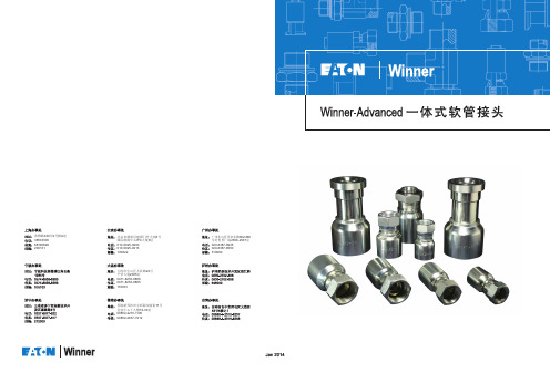
JIS BSPP 60° CONE SEAT
18611Y P17
19611Y P18
16711Y P15
26711DY P53
26711Y P54
26741Y P55
27811Y P58
87341Y P71
87391Y P72
87391Y-H P73
87641Y P75
87691Y P76
* 适用于FC686, GH663, GH781、EC110软管。 ** 适用于FC687, GH793、EC210软管。 * Design for FC686, GH663, GH781, EC110 hose。 ** Design for FC687, GH793, EC210 hose。
11
WWININNENRERADAVDAVNACNECDED一一体体式式软软管管接接头头WWININNNEERRAADDVVAANNCCEEDDOONNEEPPIEIECCEEHHOOSSEEFFITITTTIINNGG
6
04
6
04
6
04
8
05
10
06
10
06
8
05
10
06
12
08
16
10
20
12
20
12
25
16
32
20
32
20
40
24
50
32
O形圈 尺 寸 DIMENSIONS
O-RING
A
C S1
O05.3X1.8 22.5 O07.5X1.8 23.5 O08.5X1.8 23.5 O08.5X1.8 23.5 O08.5X1.8 23.5 O9.75X1.8 23.5
差压传感器的安装方法

差压传感器的安装方法引言差压传感器是一种广泛应用于工业控制和仪表领域的传感器,可用于测量流体中的压力差。
它具有灵敏度高、响应速度快、稳定性好等特点,在工程应用中得到了广泛的应用。
本文将介绍差压传感器的安装方法。
准备工作在安装差压传感器之前,我们需要准备一些必要的工具和材料:- 差压传感器- 密封垫片或硅脂- 电缆及接头- 合适的螺栓和垫片- 扳手和螺丝刀- 灯具或手电筒(用于光源)安装步骤以下是差压传感器的安装步骤:1. 确定安装位置:首先确定差压传感器的安装位置。
传感器应安装在能够准确反映流体压力的位置,避免安装在有振动、冲击或高温的地方。
2. 清洁安装位置:在安装之前,需将安装位置彻底清洁,确保表面没有灰尘、油污和其他杂物。
可以使用酒精或清洁剂擦拭表面。
3. 安装密封垫片:在传感器表面涂抹密封垫片或硅脂。
这有助于保护传感器,并确保传感器与安装位置之间的密封性。
注意,不要过度涂抹,以免影响传感器的测量精度。
4. 固定传感器:将差压传感器放置在安装位置上,并使用螺栓和垫片固定传感器。
根据情况使用扳手或螺丝刀适当地拧紧螺栓。
5. 连接电缆:将传感器的电缆与现场控制系统或仪表连接。
确保电缆连接可靠,避免松动或断开。
6. 安装附件:根据需要,可以安装附件,如温度补偿装置、防护罩等。
7. 检查安装质量:安装完成后,检查传感器的安装质量,确保传感器牢固可靠,并且与流体接点稳定。
8. 测试和校验:在使用差压传感器前,需要进行测试和校验。
使用专用设备或测试仪器对传感器进行校验,并根据校验结果调整传感器的零点和灵敏度。
注意事项在安装差压传感器时,需要注意以下事项:- 避免安装在高温或有振动的环境中,以免影响传感器的测量精度。
- 注意保护传感器表面,避免刮伤或损坏。
- 选择合适的螺栓和垫片,确保传感器的固定可靠。
不要过度拧紧螺栓,以免破坏传感器。
- 在连接电缆时,确保电缆连接牢固可靠,避免因松动而影响传感器的工作。
WGI-1020 输液泵说明书

警告
本产品应由专业临床医生,或在专业临床医生的指导下使用。使用本产品的人员 应接受专业的培训。任何没有授权或没有经过培训的人员不得进行任何操作。
IV
前
说 明
言
本使用说明书(以下简称“说明书” )详细地介绍了产品的用途、功能和使用操作。使 用本产品前,请认真阅读并理解本说明书,保证能够正确地使用本产品,确保患者和操作 者的安全。 本说明书按照最完整的配置对本产品进行介绍,部分内容可能不适用于您所购买的产 品。如果有任何疑问,请与本公司联系。 请将本说明书放置在输液泵附近,以便随时查阅。
2.1 产品简介........................................................................................................................ 2-1 2.1.1 适用范围........................................................................................................... 2-1 2.1.2 禁忌症............................................................................................................... 2-1 2.1.3 产品结构、组成及性能 ................................................................................... 2-1 2.2 产品外观........................................................................................................................ 2-3 2.2.1 前面板............................................................................................................... 2-3 2.2.2 后面板............................................................................................................... 2-6 2.3 屏幕显示........................................................................................................................ 2-7 2.4 电池................................................................................................................................ 2-7 2.4.1 概述................................................................................................................... 2-7 2.4.2 电池使用指导 ................................................................................................... 2-8 2.4.3 电池维护........................................................................................................... 2-9 2.4.3.1 优化电池性能 .................................................................................. 2-9 2.4.3.2 检查电池性能 .................................................................................. 2-9 2.4.4 电池回收......................................................................................................... 2-10 第 3 章 安装与维护 .................................................................................................................... 3-1 3.1 安装................................................................................................................................ 3-1 3.1.1 开箱检查........................................................................................................... 3-1 3.1.2 环境要求........................................................................................................... 3-1 3.1.3 电源要求........................................................................................................... 3-2 3.1.4 固定输液泵 ....................................................................................................... 3-2 3.1.5 安装电源线 ....................................................................................................... 3-3 3.1.6 安装滴速传感器(选配) ............................................................................... 3-4 3.2 维护................................................................................................................................ 3-5 3.2.1 检查................................................................................................................... 3-5 3.2.2 清洗、消毒 ....................................................................................................... 3-5 3.2.3 定期维护........................................................................................................... 3-7 3.2.4 无公害处理、回收 ........................................................................................... 3-7
Altronic 691360-1 油液传感器适配器说明书

ALTRONIC 691360-1LUBRICATION SENSOR 11.0 OVERVIEW1.1 This manual provides installation instructions and operating information for the Altronic Lubrication Sensor Adapter , model 691360-1.It is recommended that the user read this manual in its entirety before commencing operations.It is not our intention to instruct others on how to design controlsystems, nor can we assume responsibility for their safe operation. This advice is intended to help the end user install the Altronic Lubrication Sensor Adapter in such a manner as to reduce the risk of accident to personnel or to equipment.Do NOT attempt to operate, maintain, or repair the monitoredequipment until the contents of this document have been read and are thoroughly understood.1.2 The Altronic Lubrication Sensor Adapters are to be used with standard lubrication flow switches. Each adapter can monitor two individualflow switches. Combined with standard flow switches the 691360-1 forms a lubrication flow-monitoring system that responds directly to the presence or absence of properly timed lubrication pulses. If the lubrication pulses are detected as occurring consistently within the selected time interval, then the output of the 691360-1 is held in a constant OPEN or OFF state. If the lubrication pulses are not detected as occurring consistently within the selected time interval, then the output of the 691360-1 goes to a constant CLOSED or ON to ground state until the lubrication pulses return. Additionally, by connecting the outputs of 691360-1 to an Altronic Annunciator, the appropriate action can be taken to protect the equipment from damage when a lubrication system failure occurs.1.3 The Lubrication Sensor Adapter is NOT a direct shutdown device. A safety shutdown system such as an Altronic annunciator or PLC should beused in addition to the flow sensors and adapter.ALTRONIC LUBRICATION SENSOR ADAPTER2.0 INSTALLATION2.1The Lubrication Sensor Adapter should be inspected immediately afterunpacking. Check for any damage that may have occurred during shipping. If there are any questions regarding the physical integrity of the product, contact the distributor or Altronic, Inc.2.2The Lubrication S ensor A dapter is designed to be installed on reciprocatingengines and compressors or other industrial equipment using auxiliary lubrication systems. The 691360-1is designed to be mounted inside the control panel or another suitable weatherproof enclosure. The device should be protected from rain and other moisture sources at all times. Operating ambient temperature is –40°F TO +185°F (–40°C TO +85°C). Do not expose the device to temperatures outside the indicated range.2.3The circuitry of the Lubrication Sensor Adapter is powered directly byeither 12 to 24 volts DC or from the shutdown lead (+100 to +400 volts) of an industrial, negative ground, CD ignition system. The switch inputs of the adapter are internally pulled up to 5 volts and external power sources should not be connected to them. No additional external power source should ever be connected to the 691360-1 input terminals. See figure 1 for wiring connections. Each of the 691360-1 switch inputs monitors the connected lubrication flow switch for its’ state changes (switch opening and closing to ground), since either a broken field wire (open) or a field wire shorted to ground prevents the changing signal from reaching the input, these wiring failures cause a fault to be sensed. This makes the single wire connection to the flow switch Failsafe even though the flow switch is connected as a switch to ground. The output switches connect directly to the discrete inputs of any Altronic Annunciator system and can be used as Class A or Class B inputs. The OPEN DRAIN transistor outputs of the adapter are rated 100volts and 0.25 amperes maximum, and are suitable for direct connection to most industrial PLC inputs. Each output switch is independently controlled according to the status of its input switch’s current behavior. The Reset input is an optional connection, which when grounded resets both of the outputs to the OFF condition and holds them in this state until it is opened. This optional feature can be used to reset the outputs when interfacing to complex control systems.2FORM LSA II 2-08INSTALLATION INSTRUCTIONS3.0 OPERATION3.1The Lubrication Sensor Adapter should be setup to monitor for a loss oflubrication pulses from the flow switch for a period of time greater than that which is the normally expected time between lubrication pulses. The maximum time between pulses is set by adjusting a rotary switch on the device for each individual channel. The trip time is adjustable in approximately 30 second increments from about30 seconds to 4.5 minutes. Each switch position (1 to 9) is actually equalto that position number times 32 seconds for the total trip delay time.For example, switch position 5 = 5 x 32 or 160 seconds (approximately 2.5 minutes). The trip time is quartz crystal controlled and does not vary with temperature, voltage or the age of this device. Always select a trip time which is at least 30 seconds longer than the actual maximum time between pulses to avoid false trips. During normal operation of the lubrication system the LED indicator flashes on each input pulse transition, this flashing LED can be used to measure the actual time between pulses and to confirm proper operation of the flow switches. The switch position 0 setting can be used to disable the specific channel for service of the lubrication system or testing.3ALTRONIC LUBRICATION SENSOR ADAPTER fIg. 1MOUNTINg DIMENSIONS4FORM LSA II 2-085INSTALLATION INSTRUCTIONSfIg. 2WIRINg DIAgRAM。
616KD-LR低压差压传感器安装与使用说明书

Series 616KD-LR Low Range Differential Pressure TransmitterSpecifications - Installation and Operating InstructionsBulletin P-616KD-LRThe SERIES 616KD-LR Low Range Differential Pressure Transmitter senses the pressure of air and compatible gases and sends a standard 4 to 20 mA and simultaneous voltage output signal. A wide range of models are available factory calibrated to specific ranges including low ranges down to 0.1 in w.c. (25 Pa). New enclosure enables the 616KD-LR to be mounted on a 35 mm DIN rail either via its side or back DIN rail clips. The 1/8˝ NPT process connection is also available in the Series 616KD-LR.INSTALLATION1. LocationSelect a clean, dry mounting location free from excess vibration where the temperature will remain between 20 and 122°F (-6.7 and 50°C). The tubing supplying pressure to the instrument can be practically any length required, but long lengths will increase response time slightly.2. PositionA vertical position, with pressure connections pointing down, is recommended. That is the position in which all standard models are calibrated at the factory. Consult factory for other position orientations.3. Pressure ConnectionsTwo integral barbed tubing connections are provided. They are dual-sized to fit both 1/8 and 3/16˝ (3.12 and 4.76 mm) I.D. tubing. Be sure the pressure rating of the tubing exceeds that of the operating ranges. The 1/8˝ NPT process connection is available as an option as well.Electrical connections are made to the terminal block located on the top of the transmitter. Terminals are marked 1, 2, 3 and 4 as shown below. Determine which of the following circuit drawings applies to your application and wire accordingly. Shieldedcable is recommended. Ground the shield at the power supply end only.Do not exceed specified supply voltage ratings.Permanent damage not covered by warranty will result. This unit is not designed for 120 or 240 volts AC line operation.NPT Connection BlockDigital push buttons set both zero and spanIntegral DIN Rail®Printed in U.S.A. 12/17FR# 444427-00 Rev. 2©Copyright 2017 Dwyer Instruments, Inc.The connections to the transmitter are made through terminals 2 and 3 on the terminalblock as shown in Figure 2. The terminal block is removable and each of the terminals are labeled underneath the terminal block on the circuit board.The range of appropriate receiver load resistances (RL) for the power supply voltage available is given by the formula listed below. Shielded 2-wire cable is recommended for control loop wiring. Ground the shield at the power supply end only.The maximum length of connecting wire between the transmitter and the receiver is a function of wire size and receiver resistance. That portion of the total current loop resistance represented by the resistance of the connecting wires themselves should not exceed 10% of the receiver resistance. For extremely long runs (over 1,000 feet), it is desirable to select receivers with lower resistances in order to keep the size and cost of the connecting leads as low as possible. In installations where the connecting run is no more than 100 feet, connecting lead wire as small as No. 22 ga. can be used.3-Wire 0 to 10 V or 0 to 5V Voltage Operation The connection to the transmitter are made to Terminals 1, 2, and 3 on the terminal block as shown in Figure 3. The terminal block is removable and each of the terminals are labeled underneath the terminal block on the circuit board. When connecting using a DC power source, make sure the AC/DC selection jumper is not present. If the polarity of the transmitter is inadvertently reversed, the unit will not function properly, but no damage will be done to the transmitter. When connecting to an AC power source, short terminals 3 and 4. Either lead of the supply power may be connected to PWR and COM without affecting the operation of the transmitter or damage to the transmitter.The minimum receiver load is 1K Ω. The resistance due to the wire should be low compared to the receiver load resistance. While the voltage at the terminal block remains unchanged with a 10 mA current flow, resistive losses in the wiring do cause errors in the voltage delivered to the receiver. For a 1% accurate gauge, the resistance of the wires should be less than 0.1% of the value of the receiver load resistance. This will keep the error caused by the current flow below 0.1%.The connection to the transmitter are made to Terminals 1, 2, and 3 on the terminal block as shown in Figure 4. The terminal block is removable and each of the terminals are labeled underneath the terminal block on the circuit board. The AC/DC selection jumper should be set for DC operation. The voltage output and the power supply must have separate wire leads that are only joined at terminal 2 of the transmitter. Additional error may occur for the voltage output if a single wire is used or if the wires are joined at the power supply or receiver.For the current output, the maximum allowable loop resistance (wiring + receiver resistance) is dependent on the power supply. The maximum loop voltage drop mustnot reduce the transmitter voltage below 17 V. The maximum loop resistance can be calculated using the following equation:RMAX = (VPS – 17.0) / 0.02 Where VPS is the power supply voltageThe equation uses 17.0 instead of 10.0 used in current only equation. This represents the minimum voltage supply which is higher on the simultaneous output configuration due to the requirements of the voltage outputs.Shielded 4-wire cable is recommended for control loop wiring. Ground the shield at the power supply end only. Should the polarity of the transmitter or receiver be inadvertently reversed, the unit will not function properly, but no damage will be done to the transmitter.For voltage outputs, the minimum receiver load is 1K Ω. The resistance due to the wire should be low compared to the receiver load resistance. While the voltage at the terminal block remains unchanged with a 10 mA current flow, resistive losses in the wiring do cause errors in the voltage delivered to the receiver. For a 1% accurate gauge, the resistance of the wires should be less than 0.1% of the value of the receiver load resistance. This will keep the error caused by the current flow below 0.1%.ZERO ADJUSTMENTA single push button is provided to zero the transmitter. Allow transmitter to warm up for 20 minutes. The zero calibration can be set by applying zero pressure to both the pressure ports and pressing the zero button for 3 seconds.SPAN ADJUSTMENTThe span calibration can be adjusted only after setting the zero adjustment. It must be completed within 5 minutes of the last zero calibration. The span calibration button will be ignored until the zero calibration is completed. Apply pressure to the ports of the transmitter that is associated with the maximum output of the transmitter (20 mA, 5 V, or 10 V depending on output being used). Press and hold the span button for 3 seconds. On bi-directional models, separate spans can be performed on the positive and negative sides of the range.MAINTENANCE/REPAIRUpon final installation of the Series 616KD no routine maintenance is required. The Series 616KD is not field serviceable and should be returned if repair is needed. Field repair should not be attempted and may void warranty.WARRANTY/RETURNRefer to “Terms and Conditions of Sales” in our catalog and on our website. Contact customer service to receive a Return Goods Authorization number before shipping the product back for repair. Be sure to include a brief description of the problem plus any additional application notes.DO NOT EXCEED SPECIFIED SUPPLY VOLTAGE RATINGS.PERMANENT DAMAGE NOT COVERED BY WARRANTY WILL RESULT. SIMULTANEOUS OUTPUTS ARE NOT DESIGNED FOR AC VOLTAGE OPERATION.DO NOT EXCEED SPECIFIED SUPPLY VOLTAGE RATINGS.PERMANENT DAMAGE NOT COVERED BY WARRANTY WILL RESULT. SIMULTANEOUS OUTPUTS ARE NOT DESIGNED FOR AC VOLTAGE OPERATION.DO NOT EXCEED SPECIFIED SUPPLY VOLTAGE RATINGS.PERMANENT DAMAGE NOT COVERED BY WARRANTY WILLRESULT.The receiver may be connected to either the negative or positive side of the loop, whichever is most convenient. Should polarity of the transmitter or receiver be inadvertently reversed, the loop will not function properly but no damage will be done to the transmitter.2 WIRE 4-20 mA WIRINGSIMULTANEOUSVOLTAGE AND CURRENT WIRING3 WIRE VOLTAGE WIRING, AC OR DCR L = V ps - 10.0 20 mA DCThere is a 5 second delay from the time the zero or span calibration buttons is released until the time that the change incalibration takes place. This delay is used to prevent stress related offsets on the lower ranges.。
湿度(327k)

概述通常湿度的测量和记录都是采用人的毛发做为测量部件但是随着对传感器反应时间要求的提高以及湿度快速变化或者在25%的湿度条件以下-10温度测量条件的大量的出现极力推荐使用我们特别设计的的测量传感器PERNIX如果你希望订购PERNIX的设备请特别指明订购需额外价钱湿度计的显示表盘由镀铝材料制白底黑字PERNIX测量部件对我们的194~202和235E250无效194 订购号00.01940.100 000圆形湿度表适合与桌面和墙挂使用钩或钉住技术数据测量范围 5~100%RH, 2%的刻度精度 2.5%RH(定期校准)工作温度-60~70尺寸 102mm,35mm D重量 0.300Kg外表天蓝色暗色镀铬外壳198 订购号00.01980.100 000温湿度表由毛细管温度传感器组成的湿度指示器由于结合了这种功能你同时可以得到相对和绝对湿度也能得到温度和露点温度技术数据测量范围 5~100%RH-25~40尺寸 133mm,46mm D重量 0.500Kg精度 2.5%RH(定期校准)1K外表天蓝色暗灰色镀铬外壳201a 订购号00.02011.100 000这种湿度计可以作为多功能测量设备由测量以%为单位的相对湿度为单位的温度和以hPa为单位的饱和压力辅件用于仪器重新标订带泡沫入口的透明箔袋技术数据测量范围5~100%RH-30~50精度 2.5%RH(定期校准) 1.0K(<0),0.7K(>0)尺寸 81mm; 242mmH; 28mm D重量0.400Kg外表天蓝色暗灰色镀铬外壳201a 订购号00.02020.100 000 Lambrech Polymeter,这种温湿度表一体化仪表允许读出相对湿度绝对湿度温度露点温度饱和压力水蒸汽压力以及不饱和度PERNIX型号无效辅件技术数据测量范围5~100%RH0.1~80g/m³绝对湿度-30~50精度 2.5%RH(定期校准) 1.0K(<0),0.7K(>0)尺寸 81mm; 242mmH; 28mm D重量0.4Kg外表天蓝色暗灰色镀铬外壳204 订购号33.02020.008 000用于201a和202型号的单独配件湿度计重量 0.050Kg220F 50P 订购号00.02202.205 000杆型湿度计带PERNIX测量部件用于测量空气湿度和吸湿性材料的含水量绝对轻制金属制造带手柄防摔坏玻璃树脂视窗技术数据测量范围5~100%RH刻度2%RH精度 2.5%RH(定期校准)工作温度-60~70尺寸 118mm; 480mmL; 杆19X8mm重量0.600Kg外层天蓝色暗灰色金属杆末梢为黑色235E 250 订购号00.02350.125 000带支架的湿度计特别适合使用在不易到达的地方表面安装技术数据测量范围5~100%RH刻度2%RH精度 2.5%RH(定期校准)工作温度-60~70尺寸 120mm 法兰;共 280mm H重量0.400Kg外层天蓝色镀铬外环235 E125 订购号00.02350.112 500带支架的湿度计如同235E250,但是深度为125mm技术数据尺寸120mm 法兰;共155 mm H重量 0.300Kg空气湿度传感器800系列这些传感器被装配在我们的 PERNIX系列产品上既带本地显示也可用于在线测量电缆末梢带护套辅件1个回形针和一个六角罗冒 R 1”主要技术数据测量范围5~100%RH刻度1%RH精度 2.5%RH(定期校准)工作温度-60~70最大电流 60mA(~0.5W)尺寸共395 mm H(帽子105mm;80mmD)重量 1.500Kg外层天蓝色暗灰色镀铬外壳800 N 30 订购号00.08000.202.030技术参数电阻 50-30-50 Ohm,对数800 L0-100 订购号00.08000.201.010电阻 0-100 Ohm,线性800 MU 订购号00.08000.206 0?2 空气湿度传感器带电阻/电流转换器有两种不同的型号输出 0~20mA(0~100%RH) 订购号00.08000.206 0024~20mA(0~100%RH) 订购号00.08000.206 042详细技术数据电阻0-100 Ohm,线性工作温度范围 -30~70输出0(4)~20mA(0~100%RH),负载500 ohm工作电压24VDC,10%重量 1.600Kg空气温湿度传感器传感器 809被装备到PERNIX传感器和铂探头上现场湿度显示内置电子器件用于温湿度在线测量在设备顶部有电缆接头接头带护套(Pg16)主要技术数据湿度测量范围 5~100%RH精度 2.5%RH温度测量范围-60~70精度0.3K(0)其它工作温度范围-60~70最大电流60mA(电阻输出)10mA(温度输出)尺寸共395 mm H(帽子105mm;80mmD)重量 1.5Kg外壳天蓝色暗灰色镀铬外壳809 L100订购号00.08090.231 515详细技术参数电阻输出5-100-5 ohm,线性809L 0-100 订购号00.08090.231 010详细技术参数电阻0-100 ohm,线性809MU 订购号00.08090.266 0?2带2个R-I转换器2个不同的型号都有效输出 0~20mA(0~100%RH) 订购号00.08090.266 1024~20mA(0~100%RH) 订购号00.08090.266 142主要技术数据电阻 0-100 ohm,线性精度 2.5%RH温度0.3K工作温度范围-30~70输出0(4)~20mA(~0~100%RH和-30~40)最大负载500 ohm工作电压24VDC10%重量 1.7Kg电气传感器8091经济型订购号00.08091.000 000一体化温湿度传感器她的精巧和可靠的设计使得她同时适合使用在工业和气象应用技术数据湿度测量元器件电容测量范围 0~100%RH精度2%RH输出模拟信号0~1VDC阻抗>2000 ohm温度测量元器件 PT100测量范围-20~80精度0.1K输出0~1V其它工作温度范围-20~80工作电压10~30VDC,10%功耗大约0.8mA重量0.4Kg8092 订购号00.08092.130 402 精密的相对湿度和空气温度传感器可以高质量的使用在工业和气象场合7芯电缆对外连接湿度测量元器件电容测量范围 0~100%RH精度1%RH(5~95%RH)2%RH其它输出模拟信号0~1VDC阻抗>1000 ohm温度测量元器件 PT100测量范围-40~60精度0.3K输出 PT100其它工作电压10~30VDC,10%功耗最大2.5mA重量0.4Kg连接电缆适合传感器00.08092.130 420,包括插入式接头(母头)长度 3.3m辅件814 订购号00.08140.000 000传感器防护罩保护传感器不受日照和雨淋适合用于空气湿度传感器800和空气温湿度传感器809技术数据尺寸 170mmФ;440mmH安装方式直接安装到22mm的杆上重量 1.7Kg漆层镀铝防水海洋色8141经济型订购号00.08141.?00 000传感器防护罩保护传感器不受日照和雨淋适合用于直径小于25mm的传感器技术数据尺寸 120mmФ;160mmH重量0.6Kg漆层白色防紫外线和挤压的塑料请选择防护罩8141经济型(M1) 订购号00.08141.000 000带固定螺纹8141经济型(M2) 订购号00.08141.100 000带固定螺纹和接头32.08141.001 000适合传感器00.08281.xxx xxx8141, 经济型(M3) 订购号00.08141.300 000使用保护盒子替代了固定螺纹适合传感器00.08092.130 xxx815保护管由镀镍的铜制造成当风速超过6m/s时或者在空气极度污染的场合使用适合传感器800和809使用重量0.070Kg.干湿球湿度计706 订购号00.0706.000 0?0标准干湿球湿度计设计用于安装到设备内部RH的测量由垂直安放的水银温度计带弹簧吸出器决定温度和温度得出的参数由水平的水银温度计决定配带我们的干湿球表格771b一个吸湿管0.5m长的毛细管和两个塞子这种干湿球温湿度计仅仅在0.2刻度时有效最大/最小温度计请选择0.5K刻度订购号:00.07060.000 0200.2K刻度订购号:00.07060.000 050技术数据(706型号)干湿球温度计-30~5015mmФ;370mmL;0.06Kg最小/最大温度:刻度 0.5K,-40~40;15mmФ;290mmL;0.05Kg刻度 0.2K,-40~40;15mmФ;290mmL;0.06Kg尺寸600mmH,200mmW重量 2.4Kg漆层白色金属支架706H 订购号00.07061.000 0?0标准干湿球温湿度计如同706除了不带三角架这种这种干湿球温湿度计仅仅在0.2刻度时有效0.5K刻度订购号:00.07061.000 0200.2K刻度订购号:00.07061.000 050706a 订购号32.07060.006 050干湿球温湿度计的部件刻度 0.5K,-30~50;15mmФ;370mmL;0.06Kg1052a-1/2K 订购号32.10520.001 020最大温度计的部件刻度 0.5K,-30~50;15mmФ;370mmL;0.06Kg1052a-1/5K订购号32.10520.001 050最大温度计的部件刻度 0.5K,-30~50;15mmФ;370mmL;0.06Kg1052b-1/2K 订购号32.10520.002 020最大温度计的部件刻度 0.5K,-30~50;15mmФ;370mmL;0.06Kg1052b-1/5K 订购号32.10520.002 050最大温度计的部件刻度 0.5K,-30~50;15mmФ;370mmL;0.06Kg707 订购号32.07060.009 000最大温度计的部件重量0.600Kg740 订购号00.07400.009 000带折叠柄的可旋转干湿球温湿度计根据需要进行温湿度测量温度计容器也可作为防辐射保护配带我们的干湿球表格771b一个吸湿管0.5m长的毛细管和两个塞子技术数据温度范围 -10~60刻度 0.2K, -30~40刻度 0.2K精度0.2K尺寸305X60X20mm(HXWXD)重量 0.600Kg740a 订购号32.07400.003010用于740型号的温度计0.2K刻度741 订购号50.07400.004 000用于740的皮制包761 订购号00.07610.000 0?0渴式干湿度计简易型用于湿度和温度定义的标准设备根据DIN58661 标准制作的精密水银温度计适合与调整其它的温度和湿度产品双壁设计减少辐射影响两个温度计都必须在由吸尘器产生的2m/s的风速的空气流通下工作辅件带湿气的容器安装螺纹线性发条0.5m的毛细管参数校验证书干湿表771b塑料箱子需要另外订购请选择-5~600.2刻度订购号00.07610.000 010-30~400.2刻度订购号00.07610.000 020技术数据精度0.2K在测量范围的最大误差0.2K在任何10的范围内的最大误差0.1K尺寸90mm,420mmH,箱子420x285x100mm(LXWXH)重量设备 1.2公斤辅件 1Kg漆层白色吸出器镀铬管761a 订购号32.07610.003 010单独温度计761a 订购号32.07610.003 020单独温度计761,官方认证订购号00.07610.000 0?2渴型干湿度湿度计就如761型只是增加了官方认证证书请选择你需要的测量范围:-5~600.2刻度订购号00.07610.000 012-30~400.2刻度订购号00.07610.000 022761a官方认证订购号32.07610.003 012单独温度计,用于00.07610.000 012,-5~60761a官方认证订购号32.07610.003 022单独温度计, 用于00.07610.000 022,-30~40761e订购号32.07610.020 000手持式推荐用于移动测量用于固定测量的干湿球湿度计819 订购号00.8190.000 000干湿球湿度计特别用于户外使用空气湿度测量通过2个倾斜的铂电极这两个铂电极必须被保护不受辐射连续的气流必须从相反的方向连续通过防止外界影响技术参数测量范围依赖于外接的显示器/记录器/转换器精度0.1K在0时工作温度范围0以上供电230V AC;50Ha,160mA水柜容量150cm³重量 1.9Kg干湿度湿度表和便携计算器用测量值并且套用公式计算湿度值需要大量的时间因此图形或者数字干湿球湿度表被经常使用渴氏干湿球计算表德国气象服务编辑德国Friedrich Vieweg, Brauschweig出版我们的每个干湿球湿度都是由图形干湿球表提供在大气压1006.6hPa的情况下计算得出在某种高精度的调节需要下在有20hPa的偏差的情况下必须进行压力修正在大多数修正条件下我们提供便携计算器767和湿度计算表768G768G 订购号00.07680.030 000干湿球湿度表根据Sonntag计算曲线有详细的蒸汽压力和湿度修正应用的大气压力范围670~1065hPa曲线大小 Din A4(210x297mm)771b 订购号00.07710.020 000用于湿度计算的干湿球湿度表湿度范围0~100%RH环境温度范围0~100参考压力1006.6hPa表尺寸560X580mm767 订购号00.07670.001 000可编程便携计算器带湿度计算程序包含Sprung公式也能用于修正计算相对湿度和绝对湿度也能计算修正露点这个预设参数是在大气压力1006.6的情况用户也可根据自己的要求随意更改重量0.500Kg。
Trend 外围设备安装及接线

方向指示
焊接在同管径 一致的标识处
水流方向
4 量程拨码
流量计DWM2000
水流方向
11
0V
12
5
6
11
接线端子
12
5
6
量程拨码(8421拨码, 满刻度设置) 即: 输出20mA时, 对应的流速(m/s)
1, 布线: 2x(RVVP2x1.0) 2, 信号区分正负 3, 屏蔽层接地
风阀执行器-AD系列
若用于测量过滤网 注意空气压力的正负
空气压差开关DPSA
跳线成 D
1, 布线: RVV2x1.0 2, 信号不区分正负
防冻开关T/FS
传感器 感温线 风箱
跳线成 D
1, 安装于新风风管内, 热水盘管前. 2, 温感线应均匀分布在风管内.
• 1, 布线: RVV2x1.0 • 2, 信号不区分正负
空间质量传感器AQ/S
安装在室内距地高1.5m以上处; 周围无发热设备;不可安装在门口.
空间质量传感器AQ/S
跳线成 V
1, 布线: RVVP3x1.0 2, 信号区分正负 3, 屏蔽层接地
跳线成 V
室内温度传感器TB/TS
安装在门口.
跳线成 T
3 ,接线: 接常开点, 即当探头从最高 处下降到达低液位时, 输出信号为1
测量高位: 1 ,固定锤距离探头末端(L)约40cm左 右.根据水池的深度, 适当调节, 深的加 长, 浅的缩短 2 ,固定锤位于高液位下方约为h,
h=L*SIN37度 3 ,接线: 接常开点, 即当探头从最低处上升 到达高液位时, 输出信号为1
24VAC电源 24- 24+
IQ3输出端 0v out N
气压传感器及调压阀的安装(相对位置示意)

调压阀及气压传感器安装说明
一型号及参数
为了测量制动管路气压的动态变化,需要安装气压传感器,采用欧锐特科技生产的ORT-12型气体压力传感器,外形如图1所示,传感器的相关参数如表1所示。
气压传感器的位置在回馈制动调压阀之后,ABS调压阀之前,前后制动管路各有一个,在完成制动系统参数匹配与标定之后,气压传感器可以方便的拆卸,采用相应螺纹的螺栓将气压传感器的安装孔堵住,保证不漏气。
传感器电源及信号接口采用插拔式接头,在控制器附近及传感器附近各有一个接口。
图1
表1 ORT-12型气体压力传感器主要参数
参数名称参数值
量程0~1MPa
输出1~5V
响应时间1ms
工作温度-25℃~70℃
灵敏度温度系数0.01
二安装说明
如下图所示,回收制动的部件的安装位置。
图回收制动的部件在制动气路中的相对安装位置简图
从图中可见,气压传感器需要使用一个三通才能测量气路中的气压。
回馈制动调压阀需要串联在快放阀及继动阀的后面。
快放阀及继动阀原来的两个出口只使用一个,另一个堵住或接刹车灯/倒车灯传感器。
三通已经提供,需要工厂提供垫片,尺寸如附图。
仪表接线保护管及接头密封问题 措施
仪表接线保护管及接头密封问题措施
针对仪表接线保护管及接头密封问题,可以采取以下措施:
1. 选用合适的保护管材料:根据使用环境和要求选择耐压、耐腐蚀、防火等性能良好的材料。
2. 加强管路连接:使用螺纹连接、卡扣连接等方式,确保管路连接紧密,防止松动和渗漏。
3. 增加密封垫片:在接头处增加合适的密封垫片,如橡胶垫片、金属垫片等,提高接头的密封性能。
4. 涂抹密封胶:在接头处涂抹适量的密封胶,如硅胶、聚氨酯胶等,增强接头的密封性和防漏性能。
5. 定期检查维护:定期对接头和保护管进行检查,发现松动或渗漏及时进行处理,确保密封性能良好。
6. 安装压力表:在管路中安装压力表,定期检测管路内部的压力状况,及时发现和解决密封问题。
7. 培训操作人员:对操作人员进行培训,提高他们的操作技能和密封意识,确保他们能够正确安装和维护仪表接线保护管及接头。
8. 建立维护档案:建立仪表接线保护管及接头的维护档案,记录维护情况和处理方法,方便后续管理和维护。
通过以上措施的实施,可以有效解决仪表接线保护管及
接头的密封问题,提高设备的可靠性和安全性。
测压软管

■ 测压软管 该产品适用于液压油及其它矿物油介质21φ5φ20M16×2L产品型号:S100-AC-AC-0020S100-AC-AC-0030S100-AC-AC-0040S100-AC-AC-0050S100-AC-AC-0063S100-AC-AC-0080S100-AC-AC-0100S100-AC-AC-0125S100-AC-AC-0150S100-AC-AC-0200S100-AC-AC-0250S100-AC-AC-0320S100-AC-AC-0400S100-AC-AC-0500Pmax40MPa产品型号:S110-AC-AC-0020S110-AC-AC-0030S110-AC-AC-0040S110-AC-AC-0050S110-AC-AC-0063S110-AC-AC-0080S110-AC-AC-0100S110-AC-AC-0125S110-AC-AC-0150S110-AC-AC-0200S110-AC-AC-0250S110-AC-AC-0320S110-AC-AC-0400S110-AC-AC-0500Pmax63MPaL mm200300400500630800100012501500200025003200400050001620系列测试接头(见图1)(M16×2),两端安装形式相同,材料均为切削钢1.0718注释:1、 如两端均为1615系列测试接头(见图1)(M16×1.5),则订货号中的”AC-AC”改为”AB-AB”;2、 如两端均为1215系列测试接头(见图1)(安装螺纹),则订货号中的”AC-AC”改为”AA-AA”;3、 如两端均为插入系列,且最大工作压力为40 Mpa,则订货号中的”AC-AC”改为”AL-AL”;4、 如一端接G1/4(M14×1.5)压力表,则订货号中的”AC-AC”改为“AC-FA(FE)”5、 其他需求请垂询本公司技术人员■ 压力表 订货号9807-01-00.109807-01-00.409807-01-00.609807-01-01.009807-01-01.609807-01-02.509807-01-04.009807-01-06.0063mm甘油填充,1/4”BSP径向安装(背出),+/-1.6精度,不锈钢外壳,黄铜内部结构。
艾默生 罗斯蒙特 RBI pH ORP 传感器 数据表
产品数据表00813-0106-3008, Rev AD2020 年 9 月罗斯蒙特™ RBI pH/ORP 传感器用于恶劣环境应用的高性能 pH/ORP 测量罗斯蒙特 RBI pH/ORP 传感器采用多重参比液接设计,使之非常适合用在含硫化物及其他有毒离子的恶劣环境应用。
该传感器提供多种配置,能够满足广泛的应用要求。
订购信息罗斯蒙特 RBI pH/ORP 传感器主体材质为 Kynar ®,提供两种配置:一种是 ¾-in. 美制标准管螺纹 (MNPT) 外螺纹直接/浸没式,允许传感器用于 T 型管或浸没储罐;另一种是可插拔式,可以穿过球阀进行各式安装。
高性能和坚固耐用设计■坚固的 Kynar 主体和可选 O 型圈材料 (EPDM 、Viton ® 或Kalrez ™),化学抗性出色。
■可耐受高达 150 psig (1,035 kPa) 的压力■多重参比液接更大程度增加传感器寿命。
易于安装■直接/浸没式主体采用 ¾-in. NPT 前端和后部过程连接,直接安装到过程介质管道中,或连入一个 ¾-in. FNPT 接合延长管用于潜水安装。
■可插拔传感器选件可以插入球阀安装。
通用 VP8 连接■使用 Variopol (VP8) 电缆连接器选件避免了缆线缠绕,实现电缆向传感器快速电缆释放。
在线产品组态工具很多产品可使用我们的产品组态工具进行在线组态。
选择Configure(组态)按钮或访问我们的网站开始。
使用此工具内置的逻辑和持续验证,您可以更快、更准确地度组态您的产品。
内容订购信息 (2)规格...................................................................................................................................................................................................5尺寸图...............................................................................................................................................................................................6附件. (13)罗斯蒙特 RBI2020 年 9 月/Rosemount型号测量类型/电极A10 和 A11 配有 PT100 热电阻 (RTD),用于温度补偿。
蜂窝海尔CO2传感器和差分压力传感器产品介绍说明书

Sensor Selection GuideSensing for Building ApplicationsCO 2SensorsThe Honeywell CO 2 sensor includes state-of-the-art non-dispersive infrared (NDIR) technology plus a corrosion-free-designed sensing chamber that provides accurate and stable CO 2 readings for years, avoiding costly and inconvenient re-calibration. A patented gold-plated sensing chamber eliminates a primary source of dirt. Paired with a Honeywell economizer, theHoneywell CO 2 sensor can triple year-round savings over “cooling only” economizing. The sensor is used in demand control ventilation applications to maintain acceptable levels of CO 2 in the space.Differential Pressure SensorsAll Honeywell differential pressure sensors offer field selectable 4-20 mA, 0-5 Vdc and 0-10 Vdc outputs, uni- and bi-directional outputs, push button and digital inputs to zero the output, and configurable pressure ranges. Use P7640 dry media sensors in applications where you want measure extremelylow pressure, such as clean rooms, hospitals, fume hoods and computer rooms. Use the PWT Series to monitor and control pump differential pressure, chiller/boiler differential pressure drop and CW/HW system differential pressure.Enthalpy SensorsHoneywell enthalpy sensors are used with Honeywell economizer logic modules to permit the use of outdoor air as the first stage of cooling in HVAC systems. Thelong-lasting solid-state sensing elements are accurate and stable over time. Maximum economizer savings are achieved when two enthalpy sensors are connected to one economizer logic module for differential enthalpy changeover control.Specify Honeywell Sensors And SaveHoneywell sensors have always been competitively priced, and today Honeywell sensors continue to be one of the industry’s best values. Add in the fact that their ease-of-installation increases your productivity and you’ll see that Honeywell sensors are the smart, cost-effective choice.2Honeywell’s complete line of sensor's cover all necessary control applications and mounting options, making Honeywell your best sensor source.Temperature SensorsYou can count on Honeywell temperature sensors for the latest technology, accurate performance and reliability. Honeywell temperature sensors feature solid-statecomponents and are impervious to dust and dirt.They cover a variety of applications that will fit your needs from averaging, immersion and outdoor sensors to duct-mount, wall mount and strap-on sensors.Current Sensors And SwitchesHoneywell current switches can detect whether current is flowing and then transmit the status to a building management system, DDC or PLC controller. Honeywellcurrent transmitters measure the level of operating current and can be used to monitor equipment or drive other equipment with a modulating output. Both current switches and transmitters can be used to detect a motor failure, belt loss or slippage, or a mechanical failure to help prevent further damage and reduce downtime. Because Honeywell current sensors are rated at up to 250 amps, you can meet high-amp applications without the need for a transformer. And Honeywell offers current switches with a very low trip point of 0.20 amps.Humidity SensorsHighly accurate, stable humidity transducers designed for use with HVAC controllers, thermostats and direct digital controllers, Honeywell humidity sensors feature a ceramic technology that’s affected by condensation. Applications include room comfort, rooftop units, air handlers, air conditioning and anywhere relative humidity is tightly controlled.Dew Point SensorsSuitable for mounting on flat and round surfaces, the Honeywell dew point sensor is used to regulate cooling performance, switch cooling systems ON and OFF, andsignal if the temperature is approaching the dew point.YOUR BeST SeNSOR SOURCe3thermostats and non-Honeywell thermostats with remote setpoint.* F or accessing virtually any point in thecontroller, balancing from wall module, etc. **TR75s also have over twice as much memory capacity for parameters as TR71's.4GeNeRAL TeMPeRATURe SeNSORST775-SENS-STRAPT775-SENS-OATT775-SENS-WRT775-SENS-WT50021579-001aFor use with T7350 applications. bFor use with W7100.* May be used with Duct Mounting Kit- Part # 50053060-001GeNeRAL TeMPeRATURe SeNSORS5NOTE: 20K ohms NTC sensors are used with excel 10, 15, 50, 100 and 500. See controller product data sheets for details. PT1000 sensors are used with excel 15, 100, 500, and 600. See controller product data sheets for details. PT3000 sensors are used on certain excel and Microcell products. See controller product data sheets for details. 3K ohm NTC sensors are used on W7100, W7459, W7215, W7212 an dall economizer modules. 10K ohms NTC Type II sensors are used with TB7600, TB7300, and TB7600 Series communicating thermostats. 10K ohms NTC Type III sensors are used with WeBs-AX I/OModules.C7041PC7041JC7041BTB-WALLC7041DC7041FC7041R6CURReNT SeNSORSSplit CoreSolid Core7HUMIDITY , DeW POINT, CO 2and PReSSURe SeNSORSH7655B, H7625B, H7635BC7600B, H7655AC7262A1008C7232BHSS-DPSAutomation and Control Solutions In the US: Honeywell1985 Douglas Drive North Golden Valley, MN 55422-3992In Canada: Honeywell Limited 35 Dynamic Drive Toronto, Ontario M1V 63-9285 PR October 2013© 2013 Honeywell International Inc.P7640BHUMIDITY , DeW POINT, CO 2and PReSSURe SeNSORS (CONT.)50035430PWT250Follow us on Twitter: @honeywellcproYouTube:@honeywellcpro。
北方重型汽车 3305G矿用自卸车 康明斯MTAll-C350说明书

内蒙古北方重型汽车股份有限公司(NHL)零部件手册使用说明该手册按车辆总体构造的各主要结构来划分,它与车辆维修手册中所划分的章节相同。
每页目录右侧的索引号码由三部分组成:第一部分对应维修手册中的章号。
第二部分对应维修手册中章号中的节号。
第三部分是页代码号。
某些与本手册无关的章节已被省略。
在该手册示图索引页中列出了车辆各主要机构在维修手册中所对应的章号。
例如:第一章~底盘,第九章~前桥,第十四章~液压系统等。
车辆各主要机构的章节号和页代码号一并列在目录页中。
例如需要找出转向缸零部件时:1.从目录中可查出第十二章是转向机构零部件。
2.第十二章中的第五节为转向缸。
3.再找出零部件页代码,它代表了车辆系列号所需的零部件。
最后根据上述三个号码来找到所需零部件所在的页次。
例如:根据012—05—154可找到转向缸所在页。
系列号码:每本零部件手册都包括车辆系列号。
核对目录页中系列号栏目中的系列号码,来确定出适合于你所使用车辆的具体零部件的类型。
在所有零部件定货单上都应提供车辆系列号码。
零部件表:该表的格式通常是由一页详细零部件资料表以及与其相对一页上的零部件示图组成。
零部件表是按照零部件示图上标注的阿拉伯数字的顺序排印。
第一栏是阿拉伯数字序号,第二栏是该零部件的使用数量,第三栏是该零部件的件号,最后是零部件的名称。
在每一总成名称的下面,缩排一个字母位置,列出总成所包含的零件名称。
示图:在这些示图上显示出标准的总成图及各个单独零件,因不可能将每个零件的细节都精确地显示出来,所以它只能作为一般性的参考。
每张示图上的零部件都标有阿拉伯数字序号。
记下所需零件的阿拉伯数字序号,以便在零部件表中找到它的位置。
对应于这些阿拉伯数字序号的件号,可供定货时使用。
圆点号:打有圆点号的零件都属于上一个部件总成的装配件,未打圆点号者属于单独零件。
例:1.9052564 泵总成2.9058512 ·轴3.9024169 ·环4.9058132 ·控制总成5.9058135 ··弹簧6.9072162 垫圈——如果你定购了零件1,就会同时收到1~5号零件。
Festo MS系列减压阀说明书

55.2
40.2
4
B4
B5
L1
L2
L3
L4
44
83.4
92.8
34.8
5.6
45.2
99
69
17.5
54
129
98.6
41.3
6.6
41.3
22
d Internet: /catalogue/...
Subject to change – 2021/10
技术参数
尺寸 – 旋转手柄 用于安装到ß1
24
21
24
16.8
42
14.5
24
24
24
34
34
26
34
24
62
15.5
34
34
34
34
CAD 相关数据 a
型号 MS4-LR-...-WB MS4-LR-...-WBM
MS6-LR-...-WB
B1
B2
56
41
66.5
44
79.4
62
B3
B4
L1
L2
订货数据 规格
接口
压力调节范围 0.3 ... 4 bar
订货号
型号
压力调节范围 0.3 ... 7 bar
订货号
型号
集成 MS 压力表,带标准量程,显示单位 [bar],旋转手柄带闩,可用附件锁定
MS4
G1/4
q 529415 MS4-LR-1/4-D5-AS
q 529417
MS6
G1/2
q 529989 MS6-LR-1/2-D5-AS
型号
B2
MS4-LR-...-AD11
SAEJ30燃料及油软管
3.4.1合格鉴定试验——为进行合格鉴定试验,每种规格应提供一条7.6m(25英尺)长的未配管接头的软管或10条总成用作合格鉴定。为根据此标准进行鉴定,软管及软管总成必须满足以下试验要求:(a)长度变化,(b)爆破,(c)真空塌陷,(d)低温屈挠,(e)拉伸强度及伸长率,内胶层和外胶层,(f)耐热空气性能,(g)耐燃油性能,(h)耐油性能,(i)耐臭氧性能,以及(j)粘合。
28.58
1.062
1.125
26.97
28.58
1.062
1.125
22.23
7/8
22.23±0.79
0.875±0.031
30.18
31.75
1.188
1.250
25.40
1
25.40±0.79
1.000±0.031
32.54
34.93
1.281
1.375
32.54
34.93
1.281
1.375
第7节包括了中压带接头或不带接头的合成橡胶内胶层及外胶层的燃油喷射软管(SAE 30R9)。
第8节包括了油箱内的、低压、不带接头的燃料软管(SAE 30R10)。
第9节包括了用于燃料软管渗透的标准方法。
第10节包括了低渗透燃料注入及排放软管(SAE 30R11)。
第11节包括了低渗透燃料供给及回流软管(SAE 30R12)。
ASTM D 117-盐浴(Fog)试验方法
ASTM D 257-绝缘材料的DC电阻或导电能力
ASTM D 380-橡胶软管试验方法
ASTM D 412-橡胶拉伸特性试验方法
ASTM D 413-橡胶柔性衬层粘合特性试验方法
ASTM D 471-橡胶特性受流体影响的试验方法
S5LQ2211E P36(A3)2022

2
2
小臂油缸 管道系统
1
1
小臂 (R)
1
小臂 (H)
编
名称
号
4 夹子 5 连接器 6 对分夹 7 黄油嘴 8 内六角螺栓 9 内六角螺栓 10 O型圈 11 O型圈 12 止动垫圈 14 止动垫圈
(13) LQ42H00036F1 LQ42H00051F1
1 管子 2 管子 3 管子 4 管子 5 软管 6 软管 7 夹子 8 内六角螺栓 9 内六角螺栓 10 连接器 11 黄油嘴 12 O型圈 13 O型圈 14 O型圈 15 止动垫圈 16 塞子
M10×75 M10×85 M12×30 M12×70 M12×80 M10 M12 M12
S/J上部管道系统 PF1/2 1″3/16 -12UN-PF1 1″3/16 -12UN-PF1
(6) YN03H00053F1 1 管子 2 软管;L=800 3 连接器 4 连接器 5 塞子 6 O型圈 7 支承 8 夹子 9 内六角螺栓 10 内六角螺栓 11 垫圈 12 垫圈 13 螺母
1
1 连接器
1
2 连接器
1
3 TEE
2
4 O型圈
2
M12×25
5 O型圈
1
2
M10×35
(11) LQ42H00037F1
1 管子
旋转优先
2 管子
1
3 管子
1
4 管子
1
PF3/4 -1-14UNS
5 夹子
1
PF3/4 -1-14UNS
6 夹子
1
PF3/4
7 夹子
3
1B A16
8 夹子
1
9 O型圈
矿产
矿产资源开发利用方案编写内容要求及审查大纲
矿产资源开发利用方案编写内容要求及《矿产资源开发利用方案》审查大纲一、概述
㈠矿区位置、隶属关系和企业性质。
如为改扩建矿山, 应说明矿山现状、
特点及存在的主要问题。
㈡编制依据
(1简述项目前期工作进展情况及与有关方面对项目的意向性协议情况。
(2 列出开发利用方案编制所依据的主要基础性资料的名称。
如经储量管理部门认定的矿区地质勘探报告、选矿试验报告、加工利用试验报告、工程地质初评资料、矿区水文资料和供水资料等。
对改、扩建矿山应有生产实际资料, 如矿山总平面现状图、矿床开拓系统图、采场现状图和主要采选设备清单等。
二、矿产品需求现状和预测
㈠该矿产在国内需求情况和市场供应情况
1、矿产品现状及加工利用趋向。
2、国内近、远期的需求量及主要销向预测。
㈡产品价格分析
1、国内矿产品价格现状。
2、矿产品价格稳定性及变化趋势。
三、矿产资源概况
㈠矿区总体概况
1、矿区总体规划情况。
2、矿区矿产资源概况。
3、该设计与矿区总体开发的关系。
㈡该设计项目的资源概况
1、矿床地质及构造特征。
2、矿床开采技术条件及水文地质条件。
- 1、下载文档前请自行甄别文档内容的完整性,平台不提供额外的编辑、内容补充、找答案等附加服务。
- 2、"仅部分预览"的文档,不可在线预览部分如存在完整性等问题,可反馈申请退款(可完整预览的文档不适用该条件!)。
- 3、如文档侵犯您的权益,请联系客服反馈,我们会尽快为您处理(人工客服工作时间:9:00-18:30)。
矿产资源开发利用方案编写内容要求及审查大纲
矿产资源开发利用方案编写内容要求及《矿产资源开发利用方案》审查大纲一、概述
㈠矿区位置、隶属关系和企业性质。
如为改扩建矿山, 应说明矿山现状、
特点及存在的主要问题。
㈡编制依据
(1简述项目前期工作进展情况及与有关方面对项目的意向性协议情况。
(2 列出开发利用方案编制所依据的主要基础性资料的名称。
如经储量管理部门认定的矿区地质勘探报告、选矿试验报告、加工利用试验报告、工程地质初评资料、矿区水文资料和供水资料等。
对改、扩建矿山应有生产实际资料, 如矿山总平面现状图、矿床开拓系统图、采场现状图和主要采选设备清单等。
二、矿产品需求现状和预测
㈠该矿产在国内需求情况和市场供应情况
1、矿产品现状及加工利用趋向。
2、国内近、远期的需求量及主要销向预测。
㈡产品价格分析
1、国内矿产品价格现状。
2、矿产品价格稳定性及变化趋势。
三、矿产资源概况
㈠矿区总体概况
1、矿区总体规划情况。
2、矿区矿产资源概况。
3、该设计与矿区总体开发的关系。
㈡该设计项目的资源概况
1、矿床地质及构造特征。
2、矿床开采技术条件及水文地质条件。
