SD-301 SD卡控制盒-v1.1
杭州三汇信息工程有限公司SMG系列SIMBANK用户手册说明书

三汇SMG系列SIMBANKSIMBANK128SIMBANKVersion 1.0.0杭州三汇信息工程有限公司目录目录 (i)版权申明 ................................................................................................ i ii 版本修订记录......................................................................................... i v 第1章产品介绍 (1)1.1.应用场景图 (1)1.2.功能列表 (1)1.3.硬件描述 (2)1.4.指示灯信息说明 (4)第2章快速使用 (5)第3章WEB配置 (6)3.1.登录系统 (6)3.2.运行信息 (7)3.2.1.系统信息 (7)3.3.SIM信息 (8)3.3.1.SIM信息 (8)3.3.2.手机号设置 (9)3.3.3.SIM卡基本参数 (10)3.4.网络设置 (10)3.4.1.网络设置 (10)3.4.2.VPN (11)3.5.系统工具 (11)3.5.1.SIM卡方式 (12)3.5.2.软件升级 (13)3.5.3.系统参数 (16)3.5.4.系统监控 (17)3.5.5.更改口令 (17)3.5.6.网络抓包 (18)3.5.7.操作日志 (18)3.5.8.备份载入 (19)3.5.9.恢复出厂 (20)3.5.10.重启设置 (20)3.5.11.PING测试 (21)3.5.12.TRACERT测试 (22)3.5.13.访问控制 (22)附录A 主要技术/性能参数 (24)附录B 常见问题 (25)附录C SIMBANK VPN使用说明 (26)附录D 技术/销售支持 (29)版权申明本文档版权属杭州三汇信息工程有限公司所有。
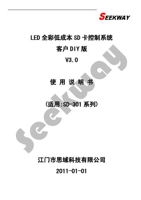
LED全彩低成本SD卡控制系统客户DIY版使用说明书V3.0
灯具类型 思域灯具 通用灯具
点光源
自定义 其它
PCB结构 思域-H16/H08/G16
思域-K06 F68/J68-思域两线6段
J69-思域两线6段 J08-思域两线8段 J12-思域两线12段 J16-思域两线16段 F16-思域两线16段
普通-8段/16段 普通-6段/12段 6803/705/6909/F01-点光源 2801-点光源 2803-点光源 9813-点光源 8806-点光源 1803-点光源 1804/1809-点光源 0805-点光源 3001-点光源 3002-点光源
LED 全彩低成本 SD 卡控制系统 客户 DIY 版 V3.0
使用说明书 (适用:Sຫໍສະໝຸດ -301 系列)江门市思域科技有限公司 2011-01-01
目录
第一章 概 述 ............................................................................... 3 1.1 思域 LED 全彩低成本 SD 卡控制系统适用方案 .................................................... 3 1.2 适用的 PCB 板类型 ........................................................................... 5 1.3 编播软件的组成 ............................................................................. 6 第二章 编辑软件说明 ............................................................................ 7 2.1 各功能按钮和区域说明 ....................................................................... 7 2.2 系统设置 ................................................................................... 8 2.2.1 第一步:软件设置 ......................................................................... 8 2.2.2 第二步:灯板设置 ........................................................................ 10 2.2.3 第三步:硬件设置 ........................................................................ 13 第三章 效果制作步骤及例子 ..................................................................... 14 3.1 编播软件主要特点 .......................................................................... 14 3.1.1 界面说明 ................................................................................ 14 3.2 软件使用说明 .............................................................................. 15 3.2.1 实时播放 ................................................................................ 15 3.2.2 动画播放 ................................................................................ 15 3.2.3 录像播放 ................................................................................ 16 3.2.4 录制功能(录像开始及录像结束) .......................................................... 17 3.2.5 录像合成 ................................................................................ 18 3.2.6 系统设置 ................................................................................ 18 3.2.7 其它功能按钮使用说明 .................................................................... 19 第 4 章 硬件调试 ............................................................................... 26 4.1 测试目的 .................................................................................. 26 4.2 更换 SD 卡内容 ............................................................................. 26 4.3 调试 ...................................................................................... 27
爱国者移动存储王3代(加速度感应安全型)
2-4 性能特点 .....................................................5
2-5 技术规格 ....................................................6
2-6 质量认证 ....................................................6
定。配合高速 USB2.0 接口和高品质,1 分钟可传输 1.3G 数据*。本产品由于具
有以上易用、安全的特性和体积小重量轻等特点,将带给您最佳的移动存储体
验。
* 本数据为爱国者实验室测试数据,用户使用时的实际速度因具体环境而不同
2-2 产品结构图
4
电源指示灯
独有黑晶凝尘标记
数据指示灯
*产品以包装内实物为准,如有改变恕不另行通知
第三章 安装说明 ................................................7
3-1 安装前注意事项 ..............................................7
3-2 Windows 98SE 下的安装过程 ....................................7
4. 速度快,移动存储王Ⅲ代的理论极限传输速率可达 480Mb/s,实际测试速 度也具有明显优势。使用顶级 USB-to-IDE 方案,传输数据安全稳定,兼 容性好。
5
5. 容量大,提供各种规格的存储容量,满足不同人士的移动存储需要。 6. 兼容性好,可同时在 USB1.1 与 USB2.0 接口下使用。 7. 携带轻便,体积小重量轻。 8. 数据可以长期保存,无须任何的特别保存环境,就可以长期的保留宝贵的
SD200-30伺服驱动器用户手册

3.5.1 开关量输入接口 ............................................................. 11 3.5.2 开关量输出接口 ............................................................. 11 3.5.3 脉冲量输入接口 ............................................................. 12 3.5.4 编码器信号差分输出接口 ..................................................... 13 3.5.5 编码器 Z 信号集电极开路输出接口 ............................................. 13 3.5.6 伺服电机光电编码器输入接口 ................................................. 13
— II —
第一章 规 格
Ⅰ 规格 -1.1(伺服驱动器规格)
1
第一章 规 格
1.1 伺服驱动器规格
型号
SP301E可编程SD卡控制器使用说明
SP301E 可编程SD卡控制器使用说明一、特点:1、上位机软件编辑花样,SD卡播放效果文件;2、多台控制器同步级联,操作人性化,接线简单方便;3、支持定制市面上常见的单线或双线的LED驱动IC;4、自带99种花样效果,炫丽灵动;5、掉电保存用户设置功能;6、电源具有防反接功能。
二、功能说明:1、供电:SP301E 支持宽电压工作DC5~24V;灯具的负极(GND)需与控制器的GND相连接;2、信号:四个信号输出口输出的TTL信号是一致的;3、运行SD效果文件:SD卡上需存储由本公司提供的上位机软件(LedSense)生成的正确才能正常工作;4、同步功能:差分信号实现多台控制器远距离级联同步运行效果;5、四个功能按键:IC :按下此键进入设置IC状态,可选择支持哪种灯具IC,重复按此键切换选择IC;M/S :重复按此键交替进入设置模式(文件)或速度状态,当数码管显示P- -XX 或Sd-XX 代表的是第XX种模式或第XX个文件,当数码管显示S- - XX 代表当前是第XX种速度;UP :在相应设置状态下,按下此键可以向上切换IC,模式,文件,速度;DOWN :在相应设置状态下,按下此键可以向下切换IC,模式,文件,速度;三、推荐接线方式:SP301E Programmable SD Card controller operating instructions 1. Features:1. With computer software for editing patterns,play patterns from files in SD card;2. Multiple controllers can be work synchronously.3. Support almost every kind of one-wire or two-wire LED-DRIVER-IC in the market;4. With 99 kinds of internal patterns,which are vivid and beautiful;5. With user setting saving functionality;6.Preventing reverse connection of power supply.2.Functions:1. Wide working voltage :DC5-24V,notice that must connect the GNDs of Controller and LED together;2. Out put signals:There are four set of out put TTL signals,all of them are the same;3. Playing files: Files in SD card must be correctly generated by our company’s LED editor software(LedSense);4. Synchronous function:Support long distance synchronous mode using differential signal.5.Four buttons:IC: Pressing this button to access in IC-setting mode,press sequentially to switch the IC types;M/S: Pressing this button sequentially to access in pattern-setting(file-setting)mode or speed-setting mode;UP: In the particular mode,pressing this button to switch IC type, mode, files or speed forwardly.DOWN: In the particular mode,pressing this button to switch IC type, mode, files or speed backwardly.3.Wire Connection:。
SP301E-M SD卡迷你编程

SP301E-M可编程MINI控制器使用说明一、特点:1.支持上位机编辑效果并播放效果文件;2.支持直接与电脑连接下载效果文件;3.支持市面上几乎所有单线或双线驱动IC;4.内置99种花样效果;5.DC5-12V宽工作电压,电源防反接功能。
二、功能说明:控制器无效果文件时将自动播放内置的99种效果,用户配合LedScene软件,可以制作无限可能的精美效果。
配合LedScene使用的方法如下:1.制作效果文件可以通过使用内置或者导入的Flash文件实现,也可以通过使用录屏功能实现;2.使用LedScene软件生成效果文件时,用户可以按需要配置:灯具类型(驱动IC型号)、像素点数、帧频、RGB顺序等参数;3.在不连接任何连线的情况下,用MicroUSB线将控制器与电脑连接,此时控制器自动切换为U盘模式,将制作好的效果文件xxx.sc(xxx为文件名)下载至控制器;4.断开控制器与电脑的连接,正确连接到灯具并正确供电,控制器将自动播放上位机软件制作的花样效果文件;5.控制器可通过MODE+与MODE-两个按键切换效果文件(无效果文件时切换内置效果),通按SPEED按键调节效果跑动速度。
三、接线方式:SP301E-M Programmable MINI controller operating instructions1.Features:ing a computer software to create vivid patterns,play patterns files inside of the controller;2.Download pattern files directly from computer to controller using MicroUSB cable;3.Support almost every kind of one-wire or two-wire LED-DRIVER-IC in the market;4.99kinds of internal patterns build inside;5.DC5-12V wide range of working voltage,preventing reverse connection of power supply.2.Functions:Controller will play the build-in patterns when there is no any pattern file in the controller;User can create vivid pattern whatever user want by using LedScene software:1.Build-in Flash files and import Flash files can be use to Make pattern files easily,user can also using the screen shooting function to capture the video form computer;2.Making sure to set the parameters right before generate the files:IC-type,Number of pixels,Frame rate,RGB order......;3.Connecting the controller to computer using a MicroUSB cable,then controller switch into Disk mode,download pattern file xxx.sc(xxx is the name of the file)into the controller and disconnect the controller;4.Connecting the controller to the LED and power it on to play pattern file;5.Patterns can be switch by pressing MODE+and MODE-buttons,Pressing SPEED button to adjust speed.3.Wire Connection:。
罗克韦尔 ControlLogix 系统 说明书

准备事宜 . . . . . . . . . . . . . . . . . . . . . . . . . . . . . . . . . . . . . . . . . . . . . . . . . . 19 1756-L7x 控制器部件. . . . . . . . . . . . . . . . . . . . . . . . . . . . . . . . . . . . . . 19
未随 1756-L6x 控制器提供的部件. . . . . . . . . . . . . . . . . . . . . . 33 1756-L6x 控制器安装. . . . . . . . . . . . . . . . . . . . . . . . . . . . . . . . . . . . . . 34 CF 卡的安装和取出 . . . . . . . . . . . . . . . . . . . . . . . . . . . . . . . . . . . . . . . 34 电池的连接与更换 . . . . . . . . . . . . . . . . . . . . . . . . . . . . . . . . . . . . . . . . 38 将控制器插入机架 . . . . . . . . . . . . . . . . . . . . . . . . . . . . . . . . . . . . . . . . 40 将控制器从机架拆下 . . . . . . . . . . . . . . . . . . . . . . . . . . . . . . . . . . . . . . 42
安装 1756-L7x 控制器 安装 1756-L6x 控制器
控制器使用入门
东方电气 CP301 扩展卡使用说明书

⏹
外形图
⏹
RJ-45脚位定义
插座
⏹
⏹
型号:SNKCBLxxGTN2 (xx 表示1R5,3,5,10)
⏹
CANopen 拨动开关设定
拨动开关SW1默认设置为OPEN ,当多机通讯时,应将离上位机最远端的CP301的拨动开关设置为120Ω,其他CP301的SW1维持出厂默认状态(OPEN )。
⏹ 安装说明(SA3)
步骤1:将PGXX 按图示方向插入控制板SLOT 2插槽;
步骤2:用螺丝刀以4-6kgf-cm 的转矩将2颗M3螺丝锁紧。
⏹
安装说明(SE3)
步骤1:关闭变频器电源。
步骤2:打开变频器上盖。
步骤3:如下图所示,以选卡架前端为支点,下压将两个卡勾卡入中壳卡槽。
图一
步骤4:将配件卡连接器对准控制板上的连接器,下压将配件卡安装到选卡架上。
图二
步骤5:用螺丝刀以4-6kgf.cm的扭力,将配件卡对角锁上两颗M3的螺丝加强固定配件卡。
配线后即可盖上上盖。
图三
图三
其它
SA3系列详细说明书、型录资料可至我司以下官网下载:
1.苏州官网:
SA3系列详细说明书、型录资料可至我司以下官网下载:
1.苏州官网:
2.台湾总部官网:
如有问题,请拨打技术服务专线:4008-566-088。
SD卡接口定义

SD卡接口定义特性:◎兼容规范版本1.01 ◎卡上错误校正◎支持CPRM◎两个可选的通信协议:SD模式和SPI模式◎可变时钟频率0-25MHz◎通信电压范围:2.0-3.6V工作电压范围:2.0-3.6V◎低电压消耗:自动断电及自动睡醒,智能电源管理◎无需额外编程电压◎卡片带电插拔保护◎正向兼容MMC卡◎高速串行接口带随即存取---支持双通道闪存交叉存取---快写技术:一个低成本的方案,能够超高速闪存访问和高可靠数据存储---最大读写速率:10Mbyte/s◎最大10个堆叠的卡(20MHz,Vcc=2.7-3.6V)◎数据寿命:10万次编程/擦除◎CE和FCC认证◎PIP封装技术◎尺寸:24mm宽×32mm长×1.44mm厚说明:本SD卡高度集成闪存,具备串行和随机存取能力。
可以通过专用优化速度的串行接口访问,数据传输可靠。
接口允许几个卡垛叠,通过他们的外部连接。
接口完全符合最新的消费者标准,叫做SD卡系统标准,由SD卡系统规范定义。
SD卡系统是一个新的大容量存储系统,基于半导体技术的变革。
它的出现,提供了一个便宜的、结实的卡片式的存储媒介,为了消费多媒体应用。
SD卡可以设计出便宜的播放器和驱动器而没有可移动的部分。
一个低耗电和广供电电压的可以满足移动电话、电池应用比如音乐播放器、个人管理器、掌上电脑、电子书、电子百科全书、电子词典等等。
使用非常有效的数据压缩比如MPEG,SD卡可以提供足够的容量来应付多媒体数据。
框图:SD卡上所有单元由内部时钟发生器提供时钟。
接口驱动单元同步外部时钟的DAT和CMD信号到内部所用时钟。
本卡由6线SD卡接口控制,包括:CMD,CLK,DAT0-DAT3。
在多SD卡垛叠中为了标识SD卡,一个卡标识寄存器(CID)和一个相应地址寄存器(RCA)预先准备好。
一个附加的寄存器包括不同类型操作参数。
这个寄存器叫做CSD。
使用SD卡线访问存储器还是寄存器的通信由SD卡标准定义。
DiGiCo SD Rack 说明书

DiGiCo SD Rack Provisional - October 2010Contents1.1 Introduction.......................................................................................1-41.1.1 Product Overview................................................................1-41.2 SD Rack Power.................................................................................1-5 1.3 SD Rack Clocking.............................................................................1-51.4 SD Rack Cards..................................................................................1-51.4.1 Analogue Mic/Line Input card (ADC).................................1-61.4.2 Analogue Line Output card (DAC).....................................1-61.5 Splits & Gain Tracking......................................................................1-61.5.1 Split Options........................................................................1-61.5.2 Gain Tracking......................................................................1-61.6 Using the SD Rack Menu System....................................................1-71.6.1 PSU Readings......................................................................1-91.6.2 I/O Card Code Versions......................................................1-91.6.3 MADI Card Code Versions..................................................1-91.6.4 Rack Defaults.......................................................................1-91.6.5 Main Display........................................................................1-91.6.6 Optocore ID & Fibre Speed...............................................1-101.6.7 USB Rack Control.............................................................1-101.6.8 Rack Sync Source.............................................................1-101.6.9 Rack Sample Rate.............................................................1-101.6.10 Rack Routing Mode.........................................................1-101.6.11 Rack Main and Aux Splits...............................................1-111.6.12 Rack Card Splits..............................................................1-111.1 Introduction1.1.1 Product Overview.................................................................The DiGiCo SD Rack is........Hot Swappable Dual Redundant PSU Hot Swappable Dual Redundant PSURack MADI/OPTOPod Input or Bidirectional CardsOutput Cards Optocore InterfaceWord ClockIN/OUTAUX MADI Split MAIN MADI SplitExternal USB Control Port SystemSettingsControlsMAIN MADI AUX MADI1.2 SD Rack PowerThe SD rack has dual redundant hot swappable power supplies. The rack should be operated with both powersupplies on whenever possible.1.3 SD Rack ClockingThe SD Rack will receive clock sync from the connected console in normal operation. It can run run at 48KHz or 96khz when clocked by the console. It is capable of running at 192KHz but this has not yet been implemented in current console software.The SD Rack can also receive sync from its own internal clock at several different sample rates - see section 1.6.9 Rack Sample Rate Additionally the rack can receive sync from an external word clock source when the word clock is connected to the rack's word clock in port.1.4 SD Rack CardsSeveral rack I/O card options are available - I/O cards normally provide blocks of 8 signals.A rack can be fitted with up to 14 I/O cards providing up to 56 inputs and 56 outputs.Card options are:Analogue Mic/Line Input card on XLRAnalogue Line Output card on XLRAES Input card on XLR or BNCAES Output card on XLR or BNCAES Bidirectional I/O card on XLR or BNCAviom card (16 outputs occupying 2 rack slots) - CAT5 connectorAES42 Mic Input card on XLR1.4.1 Analogue Mic/Line Input card (ADC)..................................The 8 Mic/Line input ADC card has 2 indicators on each socket.The orange indicator shows the status of +48V Phantom Power On/Off.The green indicator shows signal present and this turns red when the signal is close to clipping.1.4.2 Analogue Line Output card (DAC)......................................The 8 Line output DAC card has 2 indicators at the bottom of the card.The red indicator shows the status of Gain Tracking On/Off.The yellow indicator shows the status of the card Split On/Off.1.5 Splits & Gain Tracking1.5.1 Split Options........................................................................The SD Rack has several different Split options.1) Each input slot (block of 8 sockets on an input card) can be split to its relevant output slot. So slot 1 would be split to slot 8, slot 2 to slot 9 and so on. These split signals can be automatically Gain Tracked so that any change in the analogue gain on the input socket is compensated by the opposite change in digital trim on the relevant output socket.The output cards have LED indicators showing Split ON/OFF and Gain Tracking ON/OFF status.2) There are 2 dedicated MADI split ports on BNC connectors labelled MADI Split Main (MadiSM) and MADI Split Aux (MadiSX).These ports can provide either 2 independent split signals at 48KHz or a pair of split signals that contain MADI channels 1-28 and 29-56 at 96KHz.These outputs can also have automatic Gain Tracking applied to them on a per split basis. Eg. Main Split with Gain Tracking On and Aux Split with Gain Tracking Off1.5.2 Gain Tracking.......................................................................Gain Tracking can be controlled from the Rack LCD Menu system or optionally by an SD Series console.With Gain Tracking switched ON the digital trim on the split outputs works in direct relation to the analogue gain that is applied to the relevant (same numbered) input socket. Any change in the analogue gain at the input results in the opposite change being applied to the digital trim of the output split socket.If the analogue gain of an input socket starts at 0dB and with Gain Tracking On is raised to +10dB, the output split level will remain constant because it will have had a -10dB change applied to it in real time.The correct procedure to follow is to set an acceptable level of analogue gain on each input before switching the Gain Tracking function on. Once the Gain Tracking function is active it should not be switched off without careful consideration.There is also a Gain Track Reset function which sets the split output digital trim to zero. This function should also be treated with due care because using it on an active split will potentially change the output level by a large amount.1.6 Using the SD Rack Menu SystemThe LCD Menu System on the rack MADIPod is normally in a locked state and cannot be accessed.The main display will be visible and if the rack is not connected to an SD console the background colour will be light blue.If an SD console is connected and the rack is correctly receiving control data from it, the display will flash green.Pressing and holding the 2 buttons marked with left and right arrows for 2 seconds unlocks the Menu System. During the 2 seconds the display will be red and say "Locked" and when unlocked, the display will turn green and say "Unlocked".The Up/Down buttons scroll through the pages in the Menu System and the Left/Right buttons are used to select each item within pages that have multiple items. When an item's value can be changed the Up/Down arrows are used for this.If the rack is left in an idle state for 2 minutes, it will relock itself.Please refer to the following diagram for menu navigation details.1.6.1 PSU Readings.......................................................................This page shows readings for all rack PSU voltages. No adjustment is possible from the menu.1.6.2 I/O Card Code Versions.......................................................This page shows the type of card detected in each rack slot and the firmware version installed on the card.SLx indicates slot number in the range SL1 to SL14 reading left to right in the rack. Date codes are DD/MM/YY.No adjustment is possible from the menu.1.6.3 MADI Card Code Versions...................................................This page shows the MADIPod firmware versions installed on the rack. HOST, FPGA and FONT date codes are DD/MM/YY.No adjustment is possible from the menu.1.6.4 Rack Defaults........................................................................This page allows the user to set all rack parameters to their DEFAULT values.When the display shows Default Rack - Yes>, press the Right arrow button to confirm.The display will now show Default Rack - Sure>, press the Right arrow button to confirm.Using the Left arrow button will navigate back from Sure> to Yes>.1.6.5 Main Display.........................................................................The main display is always visible when the Menu System is in a locked state.It indicates:r: = The type of input/output being routed (M=MADI, O=Optocore)s: = The rack sync source (M=MADI, O=Optocore, Int=Internal, W=Word Clockidxx = The Optocore ID of the rackxxK = The sample rate being used by the rack (eg 48KHz)WMXO = The sync priority order which defaults to Word Clock, MADI Main, MADI Aux, OptocoreAn upward arrow (^) will appear underneath each of the available sources of sync.Thus if there is no valid Word Clock or MADI input to the rack, it will automatically sync to Optocore if present.If a valid Word Clock input is then connected to the rack, this will automatically become the sync source for the entire Optocore system.If multiple valid Word Clock inputs are connected to different racks, the rack with the lowest optocore ID that is receiving a Word Clock will become the sync source for the entire Optocore system.1.6.6 Optocore ID & Fibre Speed.................................................These pages show the Optocore ID of the rack in range of 11 to 24 and the fibre speed which is either 1GB or 2 GB.Each rack requires a unique ID so that it can be recognised by the rest of the Optocore system. To change the ID, scroll with the Left/ Right buttons until you reach the required number.The rack fibre speed needs to be set to the same value as all other devices in the Optocore system. The Default is 2GB and this should not be changed unless you have special requirements. There are two possible reasons to change the fibre speed to 1GB:1) If you require distances of optical fibre greater than 350M between individual devices.2) You require compatibility with Optocore's own I/O units, some of which will only operate at the 1GB fibre speed. Please consult your Optocore device documentation for the fibre speed specifications.NOTE: Using a fibre speed of 1GB will restrict the system's Optocore fibre channel count to 224 I/O at 96KHz.1.6.7 USB Rack Control................................................................This page allows selection of which rack component can be addressed by the rack USB port.When set to Opto >, the internal Optocore board can be addressed for the reprogramming of Optocore firmware - this is not required unless under specific instruction from your distributor or DiGiCo Support.When set to < Rack, the general rack control system can be addressed - this feature is not yet implemented (Nov 2010).The Default setting is < Rack.1.6.8 Rack Sync Source................................................................This page allows selection of the rack sync source.The Default setting is <AUTO> which allows automatic sync selection in the order WMXO as detailed in Main Display above.This setting can be manually overridden and a specific sync source can be set as either:<INT> = Internal sync - Rack is Master<WCLK> = External Word Clock sync - Word Clock input is Master<RxM> = MADI Main sync - MADI Main input is Master<RxX> = MADI Aux sync - MADI Aux input is Master<OPTO> = Optocore sync - Optocore is Master (normally the lowest numbered Optocore ID on the system)1.6.9 Rack Sample Rate................................................................This page allows selection of the rack sample rate.This is only possible if the Rack Sync Source is set to internal.Available options are 44.1KHz, 48KHz, 88.2KHz, 96KHz, 176KHz and 192KHz1.6.10 Rack Routing Mode...........................................................This page allows selection of the rack routing mode - which external source (MADI or Optocore) is being routed in and out of the rack. The Default setting is <AUTO> which allows automatic routing selection where the routing mode follows the sync source setting.This setting can be manually overridden and a specific sync source can be set as either:<RxM> = MADI Main routing - Input and output routing via MADI Main<RxX> = MADI Aux routing - Input and output routing via MADI Aux<OPTO> = Optocore routing - Input and output routing via OptocoreSD Rack1-111.6.11 Rack Main and Aux Splits .................................................This page controls the Main (MadiSM) and Aux (MadiSX) MADI Split functions.1) Each split can be < OFF >, < ON > or ON with automatic Gain Tracking enabled (< GT >).2) The sample rate of the split signal can also be set to be either the same as the rack's current sample rate < SYS > eg 96Khz or < SYS/2 > which is half of the rack's current sample rate. eg Rack at 96KHz and split at 48KHz.3) The MADI Type of the split can be set to standard 56 channel < 56ch >, 64 channel < 64ch > or < SD rck > which will emulate the output of the SD rack and be recognised as such by the receiving MADI device. This last type would be useful if the split was feeding anSD series console.1.6.12 Rack Card Splits.................................................................This page controls the individual output card Split functions.Each card split can be < OFF >, < ON > or ON with automatic Gain Tracking enabled (< GT >).Each input slot (block of 8 sockets on an input card) can be split to its relevant output slot. So slot 1 would be split to slot 8, slot 2 to slot 9and so on.。
301系列整合门禁说明书V1.5
目录第一章产品概述 (2)1.1 系统特点 (2)1.2 产品外观 (3)1.2.1 门禁主机外观及尺寸 (3)1.2.2 门禁读头 (3)1.2.3 产品参数 (3)1.2.4 系统基本功能 (4)第二章设备安装 (5)2.1 接口定义 (5)2.1.1 主板接口S301 (5)2.1.2 主板接口S304 (6)2.1.3 读头接口 (6)2.2 设备连接 (7)2.2.1 电锁连接 (7)2.2.2 读头连接 (9)2.2.3 开门按钮 (10)2.2.4 门磁接线 (10)2.2.5 联动报警 (11)2.2.6 报警输出 (11)2.2.7 刷卡结果指示 (11)2.2.8 通讯连接 (11)2.2.9 电源连接 (14)2.2.10 门铃连接 (14)2.3 门禁系统安装 (15)2.3.1 S301外接设备图 (15)2.3.2 S304外接设备图 (16)2.4 系统安装要求及注意事项 (16)第三章使用方法 (18)3.1 运行状态说明 (18)3.2 刷卡提示说明 (18)3.3 刷卡开门 (18)3.4 按扭开门 (18)3.5 密码开门 (19)3.6 卡+密码开门 (19)3.7 多卡开门 (19)第一章产品概述S301系列门禁机是西奥科技有限公司自主研发的新一代智能卡分体门禁系统,终端设备有门禁控制器和读卡器两部分组成,控制安全。
具有RS485/232、TCP/IP多种联网方式,适合工厂、学校、企事业单位、家庭等场所,取代传统的机械钥匙锁,一张卡代替成串的钥匙,极大的方便了现场使用。
延续S301系列门禁,S302&S304为S301的多门控制版本,说明正文中括号内参数为S302及S304参数。
无特殊说明则正文描述参数功能为S301系列S301、S302、S304共有,正文中不再分类阐述。
1.1 系统特点1.大容量储存S301(S302、S304)系统采用20M数据存储器,可以存储数据12万条(7.3万条,最多可扩展到44万条),名单量2.5万条(4.5万条),可以满足大型的门禁系统要求2.接口丰富门禁主机有维根读头接口、常开常闭电锁接口、按钮接口、门磁接口、报警输入输出接口等,方便使用,并且可以与其它防盗报警系统、消防报警系统对接联动。
方正爱微数码相框V301 说明书

方正爱·微数码相框V301用户使用手册(V1)1目录1安全使用说明 (4)2数码相框功能 (7)3硬件信息 (8)3.1数码相框接口定义 (10)4功能介绍......... (12)4.1开机画面 (11)4.2图片 (14)4.3音乐..... ..... .. (16)4.4时钟+图片 (18)4.5日历 (20)4.6设置 (21)24.6.1设置时间 (23)4.6.2闹钟 (24)4.7 Sleep/Snooze介绍 (25)5电源打开和关闭及与PC机连接 (26)5.1电源打开和关闭... .. (26)5.2与PC机连接 (27)5.3连接U盘 (27)6简单故障处理办法 (28)7 有毒有害物质说明 (29)3■为保证您的数码相框在最佳状态,请在使用前仔细阅读本手册。
■请遵守安全使用说明。
■手册中使用的图片仅作为功能示意图,可能与数码相框实物的显示有所不同,请以您的数码相框实物为准。
11.1为了防止触电,请勿暴露此数码相框在有雨或者潮湿的环境下。
禁止私自打开外壳,内部电压可能对人体造成伤害。
如数码相框有故障,请到专业维修点维修。
41.2不要晃动或敲击数码相框,可能会造成数据损坏、丢失,导致文件不可以正常播放。
请勿将数码相框暴露于潮湿环境或雨水中。
如果数码相框进水或受潮,可能会导致数码相框故障,甚至无法维修。
不要自行拆卸数码相框。
不要把数码相框暴露于沙粒或尘埃环境中。
请勿在靠近会产生强烈无线电波或放射线的场所使用数码相框,可能导致数码相框无法正常运行。
为了预防触电,请将插头完全插入插座。
保持所有电缆安全、整洁连接到数码相框,以免数码相框因为电缆排布杂乱导致跌落而被损坏。
请勿用力按压LCD屏幕。
请勿将LCD屏暴露在太阳光下,因可能导致数5码相框故障。
请使用柔软的绒布清洁荧屏表面,清除灰尘。
数码相框有故障,请送到专业维修点进行修理。
避免数据丢失,请将数码相框中的数据备份到电脑上。
ISA-301D系列通讯接口设备技术使用说明书V1.00-081229
Ver 1.00
编写: 审核: 批准:
黎强 侯 林 陈远生 徐成斌
长园深瑞继保自动化有限公司 二〇〇八年九月
本说明书由长园深瑞继保自动化有限公司编写并发布,并具有对相关产品的最终解释权。 相关产品的后续升级可能会和本说明书有少许出入,说明书的升级也可能无法及时告知阁下, 对此我们表示抱歉!请注意核对实际产品与说明书的版本是否相符。 更多产品信息,请访问互联网:
7 装置软件功能 ..................................................................................................... 8
7.1 完善的规约库 ................................................................................................................. 8 7.2 遥控允许检查 ................................................................................................................. 9 7.3 遥控闭锁检查 ................................................................................................................. 9 7.4 遥测归一化转换 ............................................................................................................. 9 7.5 信号转换和合成 ........................................................................................................... 10 7.6 事件记录....................................................................................................................... 10 7.7 打印功能....................................................................................................................... 10 7.8 调试功能....................................................................................................................... 10 7.9 远程维护....................................................................................................................... 11
AIG-301-T-CN-AZU-LX和AIG-301-CN-AZU-LX快速安装指南:高级物联网门

P/N: 1802003015020 *1802003015020*AIG-301-T-CN-AZU-LX andAIG-301-CN-AZU-LX Quick Installation GuideAdvanced IIoT gateway with Arm® Cortex™-A7 dual-core 1 GHz processor, 1 CAN port, 4 DIs, 4 DOs, ThingsPro Edge and AzureIoT Edge software, -20 to 70°C and -40 to 70°C operatingtemperature rangesVersion 1.0, December 2021Technical Support Contact Information/support2021 Moxa Inc. All rights reserved.Package ChecklistBefore installing the device, verify that the package contains the following items: • AIG-300 Series CN model advanced IIoT gateway • Power jack• DIN-rail mounting kit• Quick installation guide (printed) • Warranty cardPanel ViewsThe following figures show the panel layouts of the device.NOTEThe CN models do not come preinstalled with the LTE module. Contact Moxa’s distributor in China for more information.Top PanelFront PanelBottom Panel ViewLED IndicatorsLED Name Status FunctionPWR1/PWR2 Green Power is onOff No power is suppliedSIM Green SIM2 in useYellow SIM1 in useUSR Green/Yellow Green: System is operating normallyYellow: System is initializing and runningthe initial boot-up processL1/L2/L3 Yellow Cellular signal strengthL1+L2+L3: StrongL2+L3: NormalL3:WeakW1/W2/W3 Yellow WLAN signal strengthW1+W2+W3: StrongW2+W3: NormalW3: WeakLAN1/LAN2 (RJ45 connector) Green Steady on 1000 Mbps Ethernet linkBlinking Data is being transmitted Yellow Steady on 100 Mbps Ethernet linkBlinking Data is being transmitted Off No Ethernet connection or 10 MbpsEthernet linkMounting InstructionsDIN-rail MountingThe aluminum DIN-rail attachment plate is already attached to the product’s casing. To mount the device on to a DIN rail, make sure that the stiff metal spring is facing upwards and follow these steps.1.Pull down the bottom slider ofthe DIN-rail bracket located atthe back of the unit2.Insert the top of the DIN railinto the slot just below theupper hook of the DIN-railbracket.tch the unit firmly on to theDIN rail as shown in theillustrations below.4.Push the slider back into place.Wall Mounting (optional)The device can be mounted on to a wall using a wall-mounting kit. The optional wall-mounting kit should be purchased separately.Follow these steps to mount the device on to a wall:Step 1Use four screws to fasten the wall-mounting brackets on the left panel of the device.Step 2Use another four screws to mount the device on to a wall or in a cabinet.NOTE •Test the screw head and shank size by inserting the screws into one of the keyhole shaped apertures of the wall-mounting plates before attaching the plate to the wall. •Do not drive the screws in all the way—leave a space of about 2 mm to allow room for sliding the wall mount panel between the wall and the screws.Wiring Requirements•Use separate paths to route wiring for power and devices. If power wiring and device wiring paths must cross, make sure the wires are perpendicular at the intersection point.•You can use the type of signal transmitted through a wire todetermine which wires should be kept separate. The rule of thumb is that wiring that shares similar electrical characteristics can be bundled together.• Keep input wiring and output wiring separate.•When necessary, it is strongly advised that you label wiring to all devices in the system.NOTE Do not run signal or communication wiring and power wiring in the same wire conduit. To avoid interference, wires with different signal characteristics should be routed separately.Grounding RequirementsThere is a grounding connector located on the top panel of the device. Connect it to an appropriate grounded metal surface. Grounding and wire routing help limit the effects of noise due to electromagnetic interference (EMI).Connecting the Power SupplyConnect the power jack (in the package) to the DC terminal block (located on the top panel), and then connect the poweradapter. It takes about 3 minutes for the system to boot up. Once the system is ready, the Power LED will light up. Both models support dual power inputs for redundancy.Use wires with 12 to 26 AWG wire size to connect to V+, V-, and GND.The wire size of the power input and the earthing conductor should be the same. Remove 8 to 9 mm of the DC wires’ protective cover and use a torque of 4.5lb-in/0.51Nm to connect the wire. The max. wire temperature should not exceed 100°C. The terminal blocks do not accommodate more than one conductor wire per clamping point.Wiring the I/OsThere are four digital inputs and four digitaloutputs on the top panel. Refer to the figureon the left for detailed pin definitions.Use wires with 16 to 28 AWG wire size toconnect to DI, DO, and GND.The exposed conductor wire length should be7-8 mm and the max. wire temperatureshould not exceed 100°C. The terminal blocksdo not accommodate more than oneconductor wire per clamping point.DI Dry Contact DO Channel (Sink Type)Communication ConnectionsConnecting to the NetworkThe two 10/100/1000 Mbps Ethernet ports (LAN 1 and LAN 2) use RJ45 connectors. The pin assignments are shown in the following table:Pin 10/100 Mbps1000 Mbps 1 Tx+ TRD(0)+ 2 Tx- TRD(0)- 3 Rx+ TRD(1)+ 4 – TRD(2)+ 5 – TRD(2)- 6 Rx- TRD(1)- 7 – TRD(3)+ 8 – TRD(3)-Connecting to Serial PortsThe two serial ports (P1 and P2) use DB9 interface. Each port can be configured by software for RS-232, RS-422, or RS-485. The pin assignments for the ports are shown in the following table:Pin RS-232 RS-422/ RS-485 4w RS-485 2w 1 – TxD-(A) – 2 RxD TxD+(B) –3 TxD RxD+(B) Data+(B)4 DTR RxD-(A)Data-(A) 5 GND GND GND 6 DSR – – 7 RTS – – 8CTS––Inserting the microSD CardThe device comes with a micro-SD slot for storage expansion. The microSD slot is located at the lower part of the front panel. To install the card, remove the screw and the protection cover to access the slot and insert the microSD card into the slot.You will hear a click when the card is in place. To remove the card, push the card in before releasing it.Connecting to the Console PortThe console port is an RS-232 port located on the top panel, and can be connected to a 4-pin pin header cable. You can use this port for debugging or firmware upgrade.Pin Signal 1 TxD 2 RxD 3 NC 4GNDConnecting a USB DeviceThe device comes with a USB port located on the lower part of the front panel, allowing users to connect to a device with an USB interface. The USB port uses a type-A connector. Connecting a CAN DeviceA CAN port with a DB9 interface is located on the bottom panel. Refer to the figure below for detailed pin definitions.Pin Definition1 – 2CAN_L3CAN_GND4 –5 (CAN_SHLD)6 (GND)7 CAN_H8 –9(CAN_V+)Inserting a SIM CardThe device comes with two SIM card slots to install up to two SIM cards for cellular communication.Step 1Remove the screw on the SIM card holder cover located on the bottom panel of the device.Step 2Insert the SIM card into thesocket. Make sure you insert it in the right direction. To remove the SIM card, press the SIM card in to release and then pull out the SIM card.Connecting the AntennasThere are two cellular antennaconnectors (C1 and C2) on the front panel of the device. In addition, a GPS connector is provided for the GPS module. All three are SMA type connectors. Connect the antennas to these connectors as indicated.The device also comes with two Wi-Fi antenna connectors (W1 and W2) on the top panel of the device. Connect the antennas on the connectors as shown below. Both W1 and W2 connectors are of RP-SMA type.NOTE The optional Wi-Fi wireless module is not included in theproduct package and must be purchased separately. Refer to the “AIG-300 Series hardware manual ”, which can bedownloaded from https:// , to install the Wi-Fi module for the device.Connecting the Device to a PCYou can use a PC to access the AIG-300 Series by one of the following methods: A.Access the web console of ThingsPro Edge via LAN 2 by https://192.168.4.127:8443/. Default Username : admin Password: admin@123.B. Using SSH over the network.Refer to the following IP addresses and login information:Default IP Address Netmask LAN 1 DHCPLAN 2192.168.4.127255.255.255.0Login: moxaPassword: moxaNOTE For security reasons the SSH port is disabled by default. Youcan enable it via the ThingsPro Edge web console.TroubleshootingRebootTo reboot the device, press the Function (FN) button for 1 second. Reset to DefaultPress and hold the Function (FN) button between 7 to 9 seconds to reset the device to the factory default settings. When the reset button is held down, the USR LED will blink once every second and become steady after 7 to 9 seconds. Release the button within this period to load the factory default settings.Real-time ClockThe real-time clock is powered by a lithium battery. We strongly recommend that you do not replace the lithium battery without the help of a Moxa support engineer. If you need to change the battery, contact the Moxa RMA service team.Product SpecificationsInput Current 0.5 A @ 12 VDCInput Voltage 12 to 48 VDCPower Consumption 6.0 WOperating Temperature AIG-301-CN-AZU-LX:-20 to 70°C (-4 to 158°F) AIG-301-T-CN-AZU-LX:-40 to 70°C (-40 to 158°F)Storage Temperature(package included)-40 to 85°C (-40 to 185°F)The latest specifications for Moxa's products can be found at https://.。
301报警说明及整错指示灯连接

301报警说明及整错指示灯连接
联动报警
1.联动报警类型
与门禁系统联动的一般有防盗系统和火警系统,一般情况下,防盗系统发生时,要求门禁机关闭电锁,不让开锁,以保证财产的安全。
当有火警发生时,需要将门锁自动打开,以方便人员撤离,以保证人身安全。
所以两种报警系统发生的情况下,门禁的动作也不相同,在使用该功能时,需要用软件工具,设置启用,并指定报警输入类型。
2.报警输入接线方法
报警输入信号要求为有源信号,根据输入接口功能定义,将报警信号正极接在接口的“报警+”上,将报警信号负极接在接口的“报警-”上。
3.报警输入信号要求
电压范围为DC10V-24V,200mA。
报警输出
1.报警输出类型
当门禁机检测到有门磁报警,或输入报警有效时,就输出报警信号,驱动外接报警设备报警。
同时,门禁主板上报警指示灯发光提示有报警信号输出。
2.报警输出接线方法
报警输出信号是无源的开关量信号,如果报警设备是有源设备,可以直接将报警输出的公共端和常开端直接接入报警设备的控制接口。
报警设备是无源设备,则需要接入电源,再接报警设备。
3.报警输出信号说明
该报警输出信号是开关量信号。
外接刷卡结果指示
刷卡结果指示输出信号可以外接指示灯等设备,反应刷卡结果,如果刷卡正常开门通行,输出一路控制信号,如果刷卡不能开门通行,则输出另一路控制信号,两路信号分别接不同设备,可以明确提示刷卡结果。
如下图接线方法,绿色灯指示刷卡正常开门通行,红色灯指示刷卡不能开门通行。
AX301 黑金开发平台 用户手册说明书

文档版本控制版权申明:本手册版权归属芯驿电子公司(上海)有限公司所有, 并保留一切权力。
非经本公司(书面形式),同意,任何单位及个人不得擅自摘录或修改本手册部分或全部内容,违者我们将追究其法律责任。
感谢您购买黑金开发板,在使用产品之前,请仔细地阅读该手册并且确保知道如何正确使用该产品,不合理的操作可能会损坏开发板,使用过程中随时参考该手册以确保正确使用。
此手册不断更新中,建议您使用时下载最新版本。
软件版本:本手册使用ALTERA官方提供的Quartus12.1版本,请从ALTERA网站下载正确的版本或使用我们提供的软件版本安装。
黑金官网:黑金动力社区:黑金官方淘宝店:联系方式:************黑金微信公众号:ALINX-HEIJIN目录一、简介 (5)二、电源 (8)三、FPGA (9)四、50M有源晶振 (11)五、QSPI Flash (12)六、SDRAM (14)七、EEPROM 24LC04 (16)八、实时时钟DS1302 (17)九、USB转串口 (18)十、VGA接口 (20)十一、SD卡槽 (22)十二、LED (24)十三、按键 (24)十四、摄像头接口 (25)十五、数码管 (27)十六、蜂鸣器 (29)十七、扩展口 (30)FPGA 黑金开发平台AX301全新改版了,开发板在原来的基础上增加了一个黑金AX 标准40针的扩展口,提高了开发板的可扩展性。
这款开发板是隶属ALTERA FPGA 的入门级产品,主要针对FPGA 初学者。
AX301全新版的其它设计基本兼容原来老的AX301,使用的是ALTERA 公司的Cyclone IV 系列芯片,型号为EP4CE6F17C8,是256脚的FBGA 封装。
整个开发板的配置实用,有两路黑金标准的40针2.54标准的扩展口,一共有34*2=68个IO ,另外也引出了5V 电源,3.3V 电源,还有多路GND ,对于喜欢DIY 的玩家来说,是个非常不错的选择。
CPRM读卡器软件sd-jukebox v5中文使用说明书
硬件
中央处理器: Intel® Pentium® III 500 MHz 或更高
内存:
256 MB 或更多
可用硬盘空间: 100 MB 或更多 (依据 Windows 的版本或音频数据,会需要追加更多的可用硬盘空间。)
显示器:
高色彩 (16 位)或更高
800 x 600 像素的桌面分辨率或更高 (推荐使用 1024 x 768 像素或更高)
高级操作
播放列表 ..................................... 24
• 播放列表概述 ................................... 24 • 创建用户播放列表 ............................... 25 • 根据乐曲名和艺术家搜索结果创建用户播放列表 ..... 26 • 编辑播放列表 ................................... 27
MSC0151CD_CS_ZA MS0206KH0
SD-Jukebox 注意事项
SD-Jukebox 包含了使用加密手段的版权保护技术,以保障音乐人和音乐事业的合法权益,并保护音乐版权合法所有人 的权益。因此,使用 SD-Jukebox 时会带有下述限制。
• SD-Jukebox 在您计算机的硬盘上以加密形式录制音频数据。 如果您将文件移动或复制到其他文件夹,驱动器或者计算机上,加密的音乐数据不能被使用。
个人环绕声 ................................... 32
• 个人环绕声概述 ................................. 32 • 指定欣赏环境和音响效果 ......................... 32
用户手册v1.0

ZBKS0329|新一代工控机用户手册V1.0 北京航兴盛经贸有限公司1 随盒标准配置:附件类型数量描述Micro SD 存储卡 1 SanDisk 16G-Class4 3G 天线 1 增益3dB, 馈线长2米 WIFI 天线1增益3dB, 馈线长2米2 硬件说明:A B C D E F H I JGA: USB2.0/1.1 B: RS232 C: LAN 口/USB2.0/1.1 D: Micro USB E: 转换开关(切换维护模式) F: 耳机G: 话筒 H: 电源开关I: HDMI 座 J: 系统工作灯(绿色)/电源灯(红色)A B C D E F G3G天线端子A:跳线座(用于调试) B:C:Micro SD插槽 D:RS232E:USIM插槽 F:WIFI天线端子G:12V电源输入端子3硬件连接1.将HDMI电缆一端连入显示设备,另一端连入工控机HDMI端子2.将随机附送的Micro SD卡插入Micro SD插槽(注意顺着丝印方向金手指朝下插入)3.如有必要,插入USIM卡4.如有必要,连接3G天线和WIFI天线(注意天线的类型和接入位置)5.如有必要,连接USB设备(如键盘,鼠标,USB麦克风,USB蓝牙)6.如有必要,连接RS232线缆7.在确认所有外围设备均可靠连接后,插入12V电源适配器,并接通电源。
通电1分钟左右系统会完成自举,并点亮HDMI显示屏。
4详细参数项目 参数操作系统 Android4.0CPU 双核1.2GHz内存 1GB DDR硬盘 4GB EMMC,16GB SD卡,可支持32GB SD卡音视频 HDMI Type A接口,支持音视频输出支持麦克输入网络 射频:WCDMA,CDMA2000WIFI: 2.4GHz以太网:RJ45IO接口 USB:4路USB2.0接口,支持OTG串口:6路标准RS232串口扩展接口 抽屉式的标准SIM插口Push-Push的标准Micro SD卡插口电源需求 产品电源输入:直流12V 4A功耗 平均功耗:6 W最大功耗:24 W环境 工作温度:0℃ ~ 55℃存储温度:-10℃~ 65℃相对湿度:10 ~ 90%机械规格 铝制机箱机箱尺寸:183mm * 180mm * 50mm5主机尺寸图` 理念:品质领先,用户至上,为用户创造价值。
海康威视存储设备快速使用手册(Ver1.0)
IP SAN/NAS 存储产品快速使用手册(Version 1.0)杭州海康威视数字技术有限公司地址:浙江省杭州市马塍路36号电话:86(571)-88075998传真:86(571)-88805843网址:目录一. 硬件安装 (1)1. 硬件子系统 (1)2. 开机和关机 (2)二. 设定海康威视IP SAN/NAS的访问IP (3)三. DVR存储空间使用说明 (3)四. 建立对海康威视IP SAN/NAS存储系统iSCSI的连接 (11)五. 建立对海康威视IP SAN/NAS 的NAS连接 (16)六. 常见疑问解答 (18)七. 备注 (19)一. 硬件安装1.硬件子系统海康威视网络存储设备包括硬件子系统和软件子系统两部分,它们的安装可以独立进行,不需要按照固定的顺序去实施。
软件子系统是海康威视公司为网络存储设备而开发出来的网络存储管理系统,在网络环境中部署海康威视网络存储设备就可以正常地完成对存储的管理功能。
硬件子系统主要采用机架式机箱,以DS-A1008R为例,它内含8个硬盘槽位,通过状态指示灯可以很直观的查看系统电源,网络和磁盘等状态。
详见下图:DS-A1008R前面板图安装准备:在开始安装前,请检查以下物品是否齐全:1. 海康威视网络存储设备2. 电源线3. 千兆(百兆)网线(网线推荐用超五类(CAT 5e)线)4. 产品合格证5. 产品保修卡6. 快速使用手册以下物品需自备或选配:1. 千兆交换机(用户自备,普通的二层交换机即可)2. 机架导轨(选配件,标配不含)磁盘安装:为了保证运输安全,建议您将磁盘和海康威视网络存储设备分开包装。
请按照以下步骤安装磁盘:1. 向左按压磁盘固定弹簧扣,打开拉杆,将磁盘架沿导轨从机箱中拔出来;2. 用4个螺丝把硬盘固定到硬盘架上;3. 将硬盘架插入机箱,沿导轨推到底,并按压拉杆,以确保硬盘放到位并锁好;4. 重复以上操作,直到所有的硬盘安装完成。
- 1、下载文档前请自行甄别文档内容的完整性,平台不提供额外的编辑、内容补充、找答案等附加服务。
- 2、"仅部分预览"的文档,不可在线预览部分如存在完整性等问题,可反馈申请退款(可完整预览的文档不适用该条件!)。
- 3、如文档侵犯您的权益,请联系客服反馈,我们会尽快为您处理(人工客服工作时间:9:00-18:30)。
576
48
40
—
—
A68
—
—
—
120
—
90
240
180
※各类灯具详细参数请查阅思域护栏管介绍资料。
2、附送专业效果制作软件,用户可自行制作任意效果放入SD卡中使用。 3、可自动或手动选择效果,可调速度,可调音量(选装),可选交流同步。 4、可选音控、声控、加密、DMX512解码功能。
◆硬件参数 尺寸: 192L×122W×45H(mm) 功率: 小于3W 输入电压:交流 220V 工作温度:-20℃ ~ 70℃ 输出端口:1路 / 2路 / 8路
DMX/级联端口
GND
信号输出
信号输入
GND D-/BO D+/AO D-/BI D+/AI
◆DMX控制
◆级联方案
带D M X主控盒
控D制M台X
◆连线示意图 在不同的应用场合,电路有调整。出货前已根据工程实际要求作好相应电路设定, 用户不可随意更换其用途。灰色字体表示不使用此端口。
两线TTL电平输出,直接接思域两线灯具。
A1 B1 A2 B2 TX1 GND TX2 GND TX3 GND TX4 GND TX5 GND TX6 GND TX7 GND TX8 GND
AI BI 分控 GND
※数据重复: ※传输距离:
A68 / C11之间可串联,复制多路输出 使用优质网线,一般情况下主控与分控/信号 转换板之间可达200米到300米。分控/信号转换板 到灯具之间就近连接,优质网线可达50米。
思域科技有限公司
声控手动模式
音控手动模式
图案手动模式
模式显示值
0
※ 一般音控/声控模式都会处于前面的编号。
※ 若按【自动/音量】,则转为图案自动模式(所有图案模式轮流播放,不断循环)
SD卡使用:未关闭控制器电源前请不要插拔SD卡,以免 烧坏SD卡.
SD卡录制:具体方法请参照《SD卡录制说明书》。
RXD GND
两线
SD简易主控盒——SD-30系列
思域科技有限公司
版权所有
SD简易主控盒——SD-30系列
LED CONTROL SYSTEM
TTL电平输出,直接接灯具。
SD-301-L
单线灯具:支持1803/1809/1804/1812等芯片。
支持3001/3002/3005/3008等芯片。
2
◆基本操作 速度调节:按控制盒面板【速度】键调节播放的速度,数值越大,速度越慢。
速度显示值
普通模式 1 2 3 4 5 6 7 8 9 10 11 12
同步模式
22
24
26
28
30
※ 此速度是根据客户负载护栏管米数而定,小于实际速度的数值不显示。
※ 速度值大于20自动进入交流同步模式
模式选择:手动按控制盒面板【模式-】【模式+】按钮,选择音控或图案模式。
1
STB CLK DATA GND STB CLK DATA GND
DA GND 单线
SD-301-E
三线灯具:支持D705/6803/6909
,2801/2803,9813,8806等芯片。
2
1
STB CLK DATA GND STB CLK DATA GND
SD-301-N
四线灯具:支持595,TT6016/134
※所有输出数据相同
输出信号:TTL电平信号 / RS-485信号
※出货前根据实际要求选好相应输出端
附件: 【SD卡】 1张; 【接线端子】每路配一个;
◆安装环境 请安装在干燥的室内环境中,避免潮湿及雨水。
◆音控方案
CD
音频线
音频输入
左
右
音控端口
音频输入
左
右
GND
信号输出
信号输入
GND D-/BO D+/AO D-/BI D+/AI
/135/5026/5024等芯片
2
1
STB CLK DATA GND STB CLK DATA GND
CLK DATA GND 三线灯具
STB CLK DATA GND 四线灯具
三线RS-485输出,加A68信号转换器/C11分控控制护栏管或点光源。
SD-301F
485#1 485#2 TTL#1 TTL#2 TTL#3 TTL#4 TTL#5 TTL#6 TTL#7 TTL#8
加密解密:在加密主控试用期到期后,主控停止工作,显示窗显示跳动的“PP PP”。
利用面板按键可进行解密。具体方法请参照《主控盒解密说明书》。
控制盒错误提示说明:
代码
错误说明
原因
E01
无SD卡
E02
SD卡无响应
卡座接触不良/无SD卡 卡坏/卡不支持连续读取
音量/速度
模式
E03
无法复位SD卡
卡坏/卡不支持连续读取
E04
无法激活SD卡
卡坏/卡不支持连续读取
E05
无法读取SD卡
卡部分扇区不能读取/接触不良
E06
搜索不到特征码
录像合成未完成/卡未格式化/没有文件
自动/音量 速度 模式+ 模
E07
SD卡文件序列与控制盒不匹配
E09
控制序列与文件序列不匹配
错误SD卡文件 播放器设置与上盖显示编号不对应
主控错误提示 E01
SD-301F
485#1 485#2 TTL#1 TTL#2 TTL#3 TTL#4 TTL#5 TTL#6 TTL#7 TTL#8
A1 B1 A2 B2 TX1 GND TX2 GND TX3 GND TX4 GND TX5 GND TX6 GND TX7 GND TX8 GND
※传输距离: 使用优质网线其中一组双绞线, 一般情况下主控与灯具之间可达50米。
SD简易主控盒——SD-30系列
LED CONTROL SYSTEM
◆概述
1、SD-30控制器适用于各类LED护栏管或点光源楼宇轮廓。
灰度 256级
32级
256级
8级
16级
16级
32级
64级
16级
64级
灯具 单线(点) 三线灯具(点)
四线灯具(米)
思域两线8段/12段/16段
思域两线6段
C11
—
864
