EBV电动球阀说明书(骑马订拼版)
电动蝶阀球阀使用说明书

2.不 要在下述场所保管:
(1)有 雨水处
⑵ 超过 ω ℃的高温场所
o)灰 尘多的场所
(4)湿 度高的场所
3.验 收时因检查性能而拆开了包装必须重新包装好 ,直 到开始安装 。 4.空 气配管接 口及 电气配线接 口的塞子和盖等 ,在 空气配管工程及 电气配线工程开始 以前 ,
请 不要打开 。
5.对 于使用后再进行保管 的情况 ,请 按下述事项进行处理 :
‘
紫请预 留进线 ,手 动 时所需的空 间;
来注意 :室 外 阳光直射会造成高温 ,加 速元器件 的老化 ,甚 至失效 ;
雨水会加速胶垫 的老化 ,并 在万一防水操作不 当时,瞬 间损坏产 品;
环境温度 、流体温度条件
紫环境温度应在-25℃ ~60℃ 范 围 内;
注意 :在 零度 以下使用 时,应 使用带有 防止结露 的除湿加热器 的机 型;
可实现各种腐蚀性 、非腐蚀性 的气体 、液体 、胶状体 、颗粘物 的流量控制 。
★ 其安装与维修需注意 :
1.蝶 阀可 以安装在空 间任意角度管路上 。
2.安 装位置必须保证使用维修更换方便 。
3.允 许双 向使用 ,可 换 向使用 (安 装 时无方 向要求 )。
4.购 回阀门后将蝶 阀开启 务50,置 于室 内干燥处存放 。
★ 性能特 点:
⒈ 功能强劲 一△智能型、比例式 、开关式 、各类信号输 出型应有尽有 ;
⒉ 体积小巧一∵体积仅相当于同类产品的 35%左右: 3.轻便宜人——重量仅相当于同类产品∷的 30%左右; 4.美观大方——铝合金压铸外壳,精 细流畅、且可减少电磁干扰;
5,安 全保证——通过 AC!sO0V耐 压检测,F级 绝缘电机,安 全有保障; ⒍ 酡套简∷单——采用单相电源、外接线路简单,也 可做 3sOV直流电源;
V型球阀说明书

V型球阀使用及维护目录1.0范围┄┄┄┄┄┄┄┄┄┄┄┄┄┄┄┄┄┄┄┄┄┄┄┄32.0采用规范及标准┄┄┄┄┄┄┄┄┄┄┄┄┄┄┄┄┄┄┄33.0阀门的型号及说明┄┄┄┄┄┄┄┄┄┄┄┄┄┄┄┄┄┄34.0阀门的设计和制造┄┄┄┄┄┄┄┄┄┄┄┄┄┄┄┄┄ 35.0结构特点总结┄┄┄┄┄┄┄┄┄┄┄┄┄┄┄┄┄┄┄┄46.0测试标准┄┄┄┄┄┄┄┄┄┄┄┄┄┄┄┄┄┄┄┄┄┄51.0范围本技术说明书适用于污水处理、环保设备、电站排灰系统、矿业等行业介质易结垢、沉淀、纤维、固体颗粒、粘附密封面类介质的输送、排放。
,本技术规范书所提出的提出的是一般的技术要求,并未对一切技术细节作出规定,充分引述有关标准和规范的条文。
并有成功业绩和高效可靠的符合招标书和有关最新工业标准的产品。
同时满足国家的有关安全、环保等强制性法规、标准的要求。
2.0 采用规范及标准阀门满足下列所有最新版本的规范、规定和标准的要求:-GB12237-1989 阀门的制造标准- GB12237-89 法兰和对焊连接钢制阀门- GB12221-89 阀体长度参照标准- GB/T 9113.1 国家部法兰标准- GB/T13927-1992 阀门检验与试验- API 6FA 阀门耐火试验- ASTM A-370 钢制产品机械性能试验标准- NACE MR0175 油田设备抗硫化应力裂纹的金属材料要求- ANSI B16.47 法兰钻孔参照标准3.0 阀门的型号及说明阀门型号的说明:VQ647Y表示阀门为V型切断球阀,6表示气动传动装置,4表示法兰连接,7表示球芯形式为V型固定式,Y表示阀门的球面密封面堆焊合金钢的厚度在阀门组装完成时不小于2mm。
连接形式适合法兰。
驱动形式适合手柄、蜗轮传动、气动、电动。
压力范围0.6Mpa~6.4Mpa使用温度-70C ~500C口径范围DN25 ~DN3504.0 阀门的设计和制造气动V型切断球阀在开关时,可以自动括除密封带上的粘附的残留物,保证密封带的清洁和光滑。
球阀—产品使用说明书

Ball valves球阀使用说明书Ball Valve Operating Manual浙江石化阀门有限公司Zhejiang Petrochemical Valve Co., Ltd.二O一一年 Year 2011一用途Application球阀是一种管线阀门产品,用于接通或截断管路中的介质。
一般是处于全开或全关状态,在微开状态下可作流量的调节使用。
广泛适用于工况条件下水、气、油品等介质的各种管路中。
Ball valve is pipeline valve, used for connecting or cutting off medium in the pipelines. Normally it is at the state of opening or closing. And it couldfunction as regulating the flow when it is at the state of slightly open. It isused on the pipeline such as water, gas, oil etc.二性能规范 Performance Specification压力等级: Class150; Class300; Class600;Pressure: Class150; Class300; Class600;公称尺寸:NPS 2 ~NPS24;Nominal Size: NPS 2 ~NPS24阀体材料: ASTM A216 WCB; ASTM A351 CF8;Body Material:ASTM A216 WCB;ASTM A351 CF8;产品的设计、制造按API6D的规定;检查试验按API6D的规定;法兰连接尺寸按 ASME 的规定;结构长度按API6D的规定;Designed and manufactured according to API6D; Inspected and tested accordingto API6D;Flange ends according to ASME ; Face to face according to API 6D适用介质:水、蒸汽、油品等。
电动球阀使用说明书

型
-15Y -20Y -25Y -50Y -15Q -20Q -25Q -50Q
号 Q961F Q961F Q961F Q961F Q961F Q961F Q961F Q961F
-15Y -20Y -25Y -50Y -15Q -20Q -25Q -50Q
通径(mm) φ15 φ20 φ25 φ50 φ15 φ20 φ25 φ50
故障现象
故障原因
不 能 正 常 启 动 电机过热
1、电源不通 2、电压低 3、操作回路不通 4、切换装置复位不正确 5、污物卡死 6、微动开关触点损坏 7、电容器损坏
阀启闭过度频繁
排故措施
接通电源 调整电压 检查电路 检查复位情况 清除污物 更换开关 更换电容器 按ε=10%
咸阳三星机电科技有限责任公司
咸阳三星机电科技有限责任公司
电动机。电动机通过其齿轮式减速机构驱动输出轴,输出轴通过十字接 头去驱动阀杆,阀杆驱动球体转动而实现阀的开关。
3.1.3 减速器 为一齿轮式减速器,减速比为 291.3:1 3.1.4 行程控制机构 其形式为凸轮块式。行程控制凸轮有开向和关向之分,分别通过相应 的微动开关控制开向和关向行程。即左下凸轮通过左下微动开关控制开 向行程,右下凸轮通过右下微动开关控制关向行程。球阀行程 90°。此 机构同时附有同步信号输出机构,它的左右凸轮及相应的微动开关同时 为远(近)距离控制输出阀门状态信号(见图 1)。 3.1.5 手动—电动切换装置 其形式为全手动切换装置,仅限于安装调试或电控失灵时使用。请严 格按使用说明书操作,否则将损坏内部机构。 3.1.5.1 由电动变手动的切换方法 切断电源,手用力向上拉起手柄(见图 2),然后用扳手按盖子上规定的 90°范围和方向转动传动轴(注意:绝不可超范围操作),使传动轴上的离 合销从传动齿轮的轴向槽中滑出,使之和减速器脱离,从而可以以 1:1 的传动比操作阀门的开启和关闭。 3.1.5.2 由手动变电动的切换方法 切断电源,手用力向上拉起手柄,按盖子上规定的范围和方向用扳手 转动传动轴使手柄上指针复位到原来的位置,松开手柄,使传动轴上的离
3500-5 系列 EBV Electromatic
3500-5 系列EBV Electromatic™ 球阀系统说明手册(修订版 F)Baker Hughes 数据分类:公开除正常的操作和维护程序外,本操作手册还为用户/操作员提供重要的特定项目参考信息。
由于操作和维护理念不同,BAKER HUGHES(及其子公司和附属公司)并不打算规定具体程序,而是提供由所提供设备类型产生的基本限制和要求。
本操作手册假定操作员已经对潜在危险环境中安全操作机电设备的要求有了大致的了解。
因此,应结合适用于现场的安全规范和条例以及现场其他设备操作的特殊要求对本操作手册进行解释和应用。
本操作手册并不能囊括设备中的所有细节或变化,也不期望规定安装、操作或维护中可能遇到的每一种可能发生的意外情况。
如果客户/操作员需要更多信息或遇到具体问题,但本说明手册中并未进行充分阐述,则应将此事宜提交给 BAKER HUGHES。
BAKER HUGHES 与客户/操作员的权利、义务和责任严格限于设备供应相关合同中明确规定的权利、义务和责任。
BAKER HUGHES 并未通过发布这些说明提供或暗示与本设备或其使用有关的任何其他声明或保证。
本操作手册仅为用户/操作员提供,旨在帮助其对所述设备进行安装、测试、操作和/或维护。
未经 BAKER HUGHES 的书面批准,禁止全部或部分复制本文档。
ii | Baker Hughes© 2020 Baker Hughes 公司。
保留所有权利。
Consolidated 3500-5 系列 EBV 手册 | iii© 2020 Baker Hughes 公司。
保留所有权利。
换算表注:将 USCS 值乘以转换系数以获得公制值。
iv | Baker Hughes© 2020 Baker Hughes 公司。
保留所有权利。
目录换算表 ���������������������������������������������������������������������������������������������������������������������������������������������������������������������������������iii产品安全标示和标签系统�����������������������������������������������������������������������������������������������������������������������������������������������������2安全警告�������������������������������������������������������������������������������������������������������������������������������������������������������������������������������3安全预防措施 �����������������������������������������������������������������������������������������������������������������������������������������������������������������������4安全注意事项 �����������������������������������������������������������������������������������������������������������������������������������������������������������������������5搬运和储存 ���������������������������������������������������������������������������������������������������������������������������������������������������������������������������6保修信息�������������������������������������������������������������������������������������������������������������������������������������������������������������������������������7阀门术语�������������������������������������������������������������������������������������������������������������������������������������������������������������������������������7 3500-5 系列 EBVA. 设计特征和命名 (9)B. 环境条件 (10)C. 简介 (10)D. 3500-5 EBV 典型法兰入口 (11)E. 3500-5 EBV 典型对焊入口 (11)F. 3500-5 EBV 执行机构组件 (12)G. 压力调节器和过滤器 (14)H. 辅助供应歧管 (14)操作原理 (15)建议的安装规范 (16)一般操作说明 (18)维护说明 (19)检验和部件更换 (23)提升和搬运 (24)焊接说明 (25)拆解 (28)重新组装 (33)设置和测试 (40)操作 (43)快速参考指南 (45)维护 (46)故障检修 (47)© 2020 Baker Hughes 公司。
电动阀操作说明
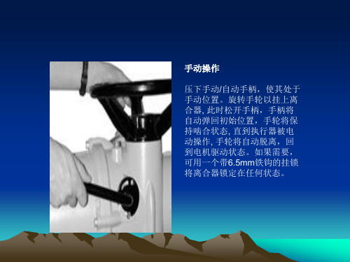
手动操作
压下手动/自动手柄,使其处于 手动位置。旋转手轮以挂上离 合器, 此时松开手柄,手柄将 自动弹回初始位置,手轮将保 持啮合状态, 直到执行器被电 动操作, 手轮将自动脱离,回 到电机驱动状态。如果需要, 可用一个带6.5mm铁钩的挂锁 将离合器锁定在任何状态。
电动操作
选择现场/停止/远程操作
执行器报警
执行器报警图标,图4.6是在一 个执行器报警实际存在时显 示。 当报警存在时,电动操作将被 禁止。 可能的原因是: • 电机温度保护跳断 • 断电时电池电量过低* • 电源故障 • 执行器控制系统报警 * 见电池报警
• 电池报警
电池报警图标,在执行器检测到电池电量过 低、完全没电或丢失时显示。 在电源接通时,执行器检测到电池没电,且 执行器电源掉电禁止操作功能[OS]有效时, 电池报警和执行器报警图标都将显示,电动 操作将被禁止。
示屏的淡黄色背景灯和一个指示阀位的指示灯也将点亮,
显示屏上可看到阀门打开的百分数或表示行程末端的符
号。
• 全开 由红灯指示灯和开启符号表示
由绿色指示灯和关闭符号表示
主电源关闭后,液晶显示器由电池供电,继续显示执行器 的阀位。无论何种情况,电池都不向背景灯和阀位指示灯 供电。
显示 – 就地指示
显示器的组成:
1. 红色 - 阀位指示灯 2. 黄色 - 阀位指示灯
2
3. 绿色 - 阀位指示灯 4. 液晶显示屏 (LCD) 5. 红外线传感器
3
1
4
6. 红外线信号确认指示灯
电动球阀使用说明书

D1
75 90 100 110 125 135 160 170 200 240 280 345 400 460
D6
40 51 58 66 76 88 110 121 150 176 204 260 313 364
n-φd
4-14 4-18 4-18 4-22 4-22 4-22 8-22 8-22 8-26 8-30 8-33 12-36 12-36 16-36
上海川沪阀门有限公司
电动球阀使用说明书
■ 主要性能指标
公称通径 允许压差 动作范围 泄露量 Q 基本误差
回差 死区 可调范围
15
20
25
32
40
50
65
80
100
125
150
≤ 公称压力(MPa)
0~90°,0~360°
按 GB/T4213-92,小于额定 KV0.01%
±1%
±1%
≤1%(可调)
125 145 160 180 210 240 295 355 410 470 525
46
56
65
76
84
99
118 132 156 184 211
根据阀门压力大小而定。配置机型不同,外形尺寸也不相同。可进入电动执行器页面查阅。
销售电话:021-5186 3046
图文传真:021-5186 3049
PN2.5MPa 法兰连接尺寸
D
95 105 115 140 150 165 185 200 235 270 300 360 425 485
D1
65 75 85 100 110 125 145 160 190 220 250 310 370 430
电动阀操作说明范文

电动阀操作说明范文电动阀是一种自动控制的阀门设备,通过电机或马达驱动阀门来打开和关闭。
它广泛应用于工业生产和家庭生活中的流体控制领域,如供水、排水、液压、气动等。
本篇文章将详细介绍电动阀的操作说明。
一、仪表和设备准备在操作电动阀之前,需要准备一些必要的仪表和设备,以确保操作的安全和顺利进行。
主要包括以下几项内容:1.阀门本体:确保阀门本体正常工作,没有渗漏或损坏。
2.电源:为电动阀供电,通常包括插座和电源线。
3.控制器:控制器通常装在电动阀上方,用于控制电动阀的开关和调节。
4.电源线和信号线:将电动阀与电源和控制器连接起来。
5.仪表设备:如电压表、电流表等,用于检测电动阀的电源电压和电流。
二、操作步骤在准备完成之后,可以按照以下步骤来操作电动阀:1.检查电源电压:首先,使用电压表等仪表设备检测电源电压是否符合电动阀的额定电压要求。
如果电压过高或过低,应及时采取措施进行调整。
2.连接电源:将电源线插入电动阀的插座中,并确保电源线与插座牢固连接。
3.连接信号线:根据电动阀和控制器的信号线接口要求,将信号线连接到相应的接口上。
通常,有两根信号线,一根用于控制阀门开关,一根用于开度调节。
4.打开电源开关:接通电源开关,电动阀将进入工作状态。
此时,可以通过观察电动阀的状态指示灯来判断电动阀是否正常工作。
5.控制开关:通过控制器上的开关按钮来控制电动阀的开关。
通常,开关按钮有开和关两个状态,分别用于打开和关闭电动阀。
6.调节开度:如果电动阀支持开度调节,可以通过控制器上的相应按钮来调节阀门的开度。
具体的开度范围和调节方式可能因电动阀的型号和厂家而异。
7.监测工作状态:在使用电动阀的过程中,应始终监测电动阀的工作状态。
可以通过观察阀门的开关情况、流体流动情况和噪音等来判断电动阀是否正常工作。
如发现异常情况,应及时采取措施进行检修和维护。
三、注意事项在操作电动阀时,需要注意以下几点事项,以确保操作的安全和有效性:1.定期检查和维护:电动阀是机械设备,需要定期进行检查和维护。
EBV说明书全文(PCV阀)1
Consolidated®安装、操作与维护手册带有2537控制台和3539控制器的Consolidated®电动球阀系统德莱塞测量与控制部美国路易斯安那州亚历山大市71309-14302002年10月修订版目录章题目页Ⅰ.安全注意事项 (4)Ⅱ. 安全防护措施 (5)III.产品安全标识系统 (6)IV.安全警告 (6)V.质量保证 (9)VI.介绍 (10)VII.系统的设计特点 (10)VIII.操作原理——电气系统 (11)Ⅸ. 安装前的保管及搬运 (14)Ⅹ. 安装操作建议 (15)A.主阀 (15)B. 3539型控制器 (16)Ⅺ. 水压试验 (17)Ⅻ. 系统的启动 (17)A. 启动前的检查 (17)B.系统启动 (17)C.调整设定压力及回座 (17)D.最低的回座设定 (19)B. 执行机构组件的拆卸 (22)C. 阀杆的拆卸 (23)ⅩⅣ. 清洗 (24)ⅩⅤ. 检查 (24)ⅩⅥ. 维护 (24)A. 阀座泄漏 (24)C. 填料泄漏 (27)D. 电气系统 (28)ⅩⅦ. 重新装配 (31)A.润滑 (31)B.所需工具 (31)C. 阀门装配 (31)ⅩⅧ. 库存 (33)A.概要 (33)B.库存计划-替换零件列表 (33)C.建议使用的备件 (34)D.识别并定购要件 (34)XIX.维护工具 (35)XX.厂商现场服务与维修计划 (38)A.厂家设定与现场设定 (38)B.现场服务 (38)C.厂家的维修设施 (38)Ⅰ.安全注意事项正确地安装, 使用及维护对於阀门产品的安全和可靠运行是必不可少的。
由德莱赛阀门业务部推荐和本说明书中所述的有关程序是完成所需作业的有效方法。
重要的一点应指出,本说明书包括了应仔细阅读的各种"安全信息",使对人身伤害危险性降至最低,或使采用不正确的程序而损坏德莱赛阀门产品的可能性降至最低,或降低使产品不安全的因素。
Series EVA电动阀控制器说明书

POWER CONNECT CONNECTOR ACTUATOR BRACKET
U-TYPE CONNECTOR
4-57/64 [124.22]
3-15/16 [100]
EVA2 & EVA3 Series
EVA1
EVA2/EVA3
The Series EVA Electric Actuators are designed to mount directly onto the Series GV globe valves, creating a complete, low cost, and compact control valve package. Floating or modulating control inputs are available, and the 24 VAC synchronic motor includes a magnetic clutch to protect the motor in stall conditions. Actuators are ruggedly constructed with a fire-proof ABS housing and robust aluminum bracket. Features include a visual position indicator and manual override to make this actuator an excellent choice for any size area, large or small.
VALVES
Valves, Globe
CONTACT US | U.S. 219/879-8000 | U.K. (+44) (0)1494-461707 | A.U. (+61) (0) 2 4272 2055 | China +852-23181007
球阀使用说明书英文版(ball valve)
Product Manual- Operation and Maintenance Manual Product Name:API 6D Ball ValveJanuary 20121ScopeThis manual covers manually/motor/pneumatic operated seat supported /trunnion supported ball valve having tow/three pieces body with nominal sizes DN 15mm-1200mm (1/2”-48”) and class ranges PN1.6MPa-10MPa(ANS1 class 150-2500).Valve ends may be threaded, flanged, butt-welded or socket2 Applications2.1 Ball valves are used to open/close the flow in pipeline.2.2 The nature of applicable fluid depends on valve material:2.2.1 Carbon steel valve applies to non-corrosive fluid, such as water, vapor or oil etc. 2.3 Temperature range depend on sent material:PTFE ≤130℃RPTFE ≤160℃PPL ≤300℃NYLON ≤121℃3. standard:Basic design API 6D-2008Inspe crlon tesring BS EN 12266.1-2003End flange ASME B16.5-2009TEMP. & PRESSURE ASME B16.34-2009Face toface ASME B16.10-2009Main parts and materials ASME materials, see Table 1Figure 1:Trunnion Ball Valve4 Structure4.1 Ball Valve structure is shown in Fig. 1.4.2 List the major components and materials shown in Table 1:Table 1: Major Parts and Materials-29℃~38℃working pressure(bar)50℃working pressure(bar)100℃working pressure(bar)121℃working pressure(bar)6 OperationThe valve can be manually operated by using the handle for manually operated valves or motor-operated by the electric actuator for motor operated valves or pneumatic operated by pneumatic actuator for pneumatic operated valves. The valve open or closes by turning the ball. Clockwise turning to 90ºresults in valve open.6.1 The manually operated valve is opened when the handle and the position mark on stem end are parallel to pipeline. When that is perpendicular to the pipeline, the valve is closed.6.2 For motor/pneumatic operated valves, valve open/close is indicated by the positioner on the electric/pneumatic actuator.7 Storage, maintenance, installation and service7.1 The valve should be stored in dry room with good ventilation. Valve ends should be covered.7.2 For valve stored for a long period of time, regular checkup is required to ensure that the valves are in good conditions. Foreign particles should be removed and special care should be taken to keep the valve seat sealing surface clean and prevent any damage of sealing surface.7.3 Check the conformance of valve identification to the service requirements prior to installation.7.4 Check the cleanness of the valve cavity and sealing surface and sealing surface and wipe off any dirt with white cloth prior to installation.7.5 Before installation, the tightness of packing should be checked to ensure that sealing is secured without affecting the turning of stem.7.6 The valve shall be in full open position when conducting system or pip line pressure test after the valve installation.7.7 Ball valve shall be in full open or full close position while in service. partial opening for controlling the flow is not allowed.7.8 Manually operated valve should be operated by using the handle. Use of lowers or other tools is not allowed.7.9 Valve in service should be examined at prescribed intervals to see whether the wear of sealing surface or stem occurs and the gasket or packing fails. Repair or replacement shall be carried out timely if necessary.7.10 “Electric valve actuator instruction manual” and “Pneumatic valve actuator instruction manual” should be referred with regard to the storage, maintenance, installation and service for motor-operated valve and pneumatic-operated valve respectively.8 Possible troubles, causes and solutions see table9 GuaranteeGuarantee period is one year after service date no later than 18 months after delivery date. Valve failure due to material defectives, manufacturing problems, design unreasonable or any damage under normal operating conditions will be repaired or parts replaced free of charge by manufacturer within the guarantee period.。
电动球阀使用说明书

n-φd
4-14 4-14 4-14 4-18 4-18 4-18 8-18 8-18 8-22 8-26 8-26 12-26 12-30 16-30
PN4.0MPa 法兰连接尺寸
D
95 105 115 140 150 165 185 200 235 270 300 375 450 515
D1
65 75 85 100 110 125 145 160 190 220 250 320 385 450
H
44.5 49 55 65 65 75 90 95 115 127 140 172.5 310 350
H1、A1
根据所配气动执行机构而定
PN1.6MPa 法兰连接尺寸
D
95 105 115 140 150 165 185 200 220 250 285 34010 125 145 160 180 210 240 295 355 410
PN2.5MPa 法兰连接尺寸
D
95 105 115 140 150 165 185 200 235 270 300 360 425 485
D1
65 75 85 100 110 125 145 160 190 220 250 310 370 430
D2
46 56 65 76 84 99 118 132 156 184 211 274 330 389
● 阀内件
阀芯形式 流量特性
O 型球体阀芯 近似快开型
● 执行机构
执行器型号
CHR 系列角行程执行机构
电源:AC200/220V,50/60Hz、输出力矩:50N·M~2000N·M、动作范围:0~90°,0~360°
主要技术参数
动作时间:15 秒/30 秒/60 秒 保护装置:过热保护、手动操作:同附带手柄操作、限位:电气、机械二重限位
Taco 电子球阀(EBV)分区阀规格说明书
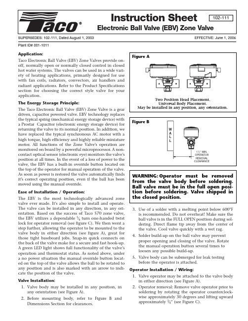
Application:Taco Electronic Ball Valve (EBV) Zone Valves provide on-off, normally open or normally closed control in closed hot water systems. The valves can be used in a wide vari-ety of heating applications, primarily designed for use with fan coils, radiators, convectors, air handlers and radiant applications. Refer to the Product Specifications section for choosing the correct style valve for your application.The Energy Storage Principle:The Taco Electronic Ball Valve (EBV) Zone Valve is a gear driven, capacitor powered valve. EBV technology replaces the typical spring (mechanical energy storage device) with a Prostar Capacitor (electronic energy storage device) for returning the valve to its normal position. In addition, we have replaced the typical synchronous AC motor with a high torque, high efficiency and highly reliable miniature motor. All functions of the Zone Valve’s operation are monitored on board by a powerful microprocessor. A non-contact optical sensor (electronic eye) monitors the valve’s position at all times. In the event of a loss of power to the valve, the EBV has a built-in override button located on the top of the operator for manual operation of the valve.As soon as power is restored the valve automatically finds it’s correct operating position, even if the ball has been moved using the manual override.Ease of Installation / Operation:The EBV is the most technologically advanced zone valve ever made. It’s also simple to install and operate.The valve can be installed in any direction, in any ori-entation. Based on the success of Taco 570 zone valve,the EBV utilizes a dependable 1⁄4turn one-handed twist lock for operator removal (see figure C). We then went a step further, allowing the operator to be mounted to the valve body in either direction (see figure A), great for those tight baseboard jobs. Snap-in quick connects on the back of the valve make for a secure and fast hook-up.A green LED light shows full functionality of the valve’s operation and thermostat status. As noted above, under a no power situation the manual override button locat-ed on the top of the valve allows the ball to be rotated to any position and is also marked with an arrow to indi-cate the position of the valve. Valve Installation:1.Valve body may be installed in any position, inany orientation (see Figure A).2.Before mounting body, refer to Figure B andDimensions Section for clearances.e of a solder with a melting point below 600°Fis recommended. Do not overheat! Make sure the ball valve is in the FULL OPEN position during sol-dering. Direct flame tip away from the center of the valve. Cool valve quickly with a wet rag.4.Solder build-up on the ball valve may preventproper opening and closing of the valve. Rotate the manual operation button several times to loosen any possible build-up.5.Valve body can be submerged for leak testingbefore the operator is attached.Operator Installation / Wiring:1.Valve operator may be attached to the valve bodyin either direction (see Figure A).2.Operator removal: Remove valve operator prior tosoldering by rotating the operator counterclock-wise approximately 30 degrees and lifting upward approximately 3⁄4” (see Figure C).SUPERSEDES: 102-111, Dated August 1, 2003EFFECTIVE: June 1, 2006Plant ID# 001-10113.To re-assemble operator to valve body: Positionoperator such that the “D” shaped valve stem aligns properly with the “D” shaped operator drive cavity (Note: The “D” shaped stem design allows for correct insertion every time). Next, slide valve stem into operator cavity and rotate until the oper-ator slips over the valve’s locking posts (see Figure C), once the operator is flush with valve body, turn operator clockwise and lock into position.4.Wire valve in accordance with system require-ments, see wiring diagrams.5.The plug-in quick connects can be disconnectedfrom the valve operator for ease of wiring. Insert the corresponding wire into the quick connects (see wiring diagrams) and tighten by turning the screw. 6.On a 24v system do not jumper power/motor (24VAC) connection terminals, even temporarily.This may cause damage to the thermostat’s heat anticipator.Mode of Operation, Start-Up:1.Upon initial field installation the capacitorrequires a full charge, approximately 30 seconds before the valve starts to turn. Do not disconnect power to the actuator for at least 1 minute after valve turns.2.When the capacitor is charging the green LEDlight will FLASH.3.Once the capacitor is charged the green LED willstop flashing but remain ON, at this point the valve’s operator will rotate the ball valve until it finds its “home” (the valves position when the thermostat is calling). The “home” position, either open or closed, is dependent on the style of valve purchased (either normally opened or normally closed).NOTE: As the valve finds its “home” it may need to travel almost 180°, depending on the initial ball position. If it rotates past a 90°point it will close the end switch (T T terminals) to verify connec-tion. This may make it seem as if the device (i.e.boiler) connected to the end switch terminals has short cycled while the valve finds its “home”. This will only occur once on initial start-up.4.Once the valve finds its “home” the green LED willremain ON as long as the thermostat is calling.5.Once the thermostat is satisfied the green LED willturn OFF and the Prostar Capacitor will discharge some of its stored energy to rotate the valve 90°into its normal position. For example: If the actu-ator is an NC (normally closed) version, the oper-ator would open the valve when the thermostat calls. Once the thermostat is satisfied the operator would then rotate the valve 90°to its normally closed position. Mode of Operation:1.When the thermostat calls, the green LED will startto FLASH for a short period of time as the Prostar Capacitor completely refills its charge.2.The green LED will then turn ON and the operatorwill rotate the valve 90°into position.3.The green LED will stay ON as long as the ther-mostat is calling.4.Once the thermostat is satisfied, the green LEDwill turn OFF and the valve will rotate 90°to its normal position.VALVE SIZECv (Kv)/Ft.of PIPE EQUIV.*CLOSE-OFF PSI (kPa)1⁄2”4.9 (4.3) / 9.50-125 psi (0-862 kPa)3⁄4”10.3 (8.9) / 8.40-125 psi (0-862 kPa)1”8.9 (7.7) / 47.40-125 psi (0-862 kPa)Flow Coefficients and Maximum Close-Off Pressure:*At 4' per second (max.recommended residential flow rate).Product Specifications:Maximum Operating Pressure:300 PSI (2,100 kPa)Maximum Shutoff Pressure:125 PSI (875 kPa)Fluid Temperature Range:20°to 240°F, (-7°to 115°C) @ 135°F (57°C) ambientInstallation must be in a non-condensing application.Service:Closed systemsHot Water, up to 50% GlycolBall Rotation Speed:Full Open to Full Close (90°turn), 4 secondsFull Close to Full Open (90°turn), 6 seconds Seat Leakage:Drop-Tight Close-OffElectrical Rating: 24 VAC, 60 HZ, 0.54 AmpsDo not exceed number of valves per transformer rating. Example:Do not use more than 12 zone valves per 40VA transformer.Power Consumption, Charging:12.84 Watts, 0.54 Amps MaxPower Consumption, Power On: 1.44 Watts, 0.06 Amps MaxHeat Anticipator Setting:0.5 AmpsEnd Switch Rating: 3 Amps @ 24 VACMaterials of Construction, Actuator:Body:High Performance Engineered PolymerGears:High Performance Internally Lubricated Engineered PolymerMaterials of Construction, Valve:Body:Forged BronzeStem:BrassPress Ring:BrassBall:Brass (Chrome Plated)Seat:Modified TeflonO-rings:EPDM“QUICK ORDER” PART NUMBERSE050C2-1 > 1⁄2" 2-Way, Sweat, 24 VAC, Normally Closed, 4 Input Quick ConnectsE075C2-1 > 3⁄4" 2-Way, Sweat, 24 VAC, Normally Closed, 4 Input Quick ConnectsE100C2-1 > 1" 2-Way, Sweat, 24 VAC, Normally Closed, 4 Input Quick ConnectsE050T2-1 > 1⁄2" 2-Way, Threaded, 24 VAC, Normally Closed, 4 Input Quick Connects E075T2-1 > 3⁄4" 2-Way, Threaded, 24 VAC, Normally Closed, 4 Input Quick Connects E100T2-1 > 1" 2-Way, Threaded, 24 VAC, Normally Closed, 4 Input Quick ConnectsD O IT O NCE. D O IT R IGHT.™TACO, INC., 1160 Cranston Street, Cranston, RI 02920T elephone: (401) 942-8000FAX: (401) 942-2360.TACO (Canada), Ltd., 6180 Ordan Drive, Mississauga, Ontario L5T 2B3.T elephone: 905/564-9422.FAX: 905/564-9436. Visit our web site at: Printed in USA Copyright 2006 TACO, Inc.Electronic Ball Valve (EBV) Zone Valve Wiring Diagrams。
EBV(T)-PR系列的气压防护球阀说明说明书

Page 2 – Bulletin 50-10-1FEATURES • Allows for positive shut-off in one direction and flow in the other direction whenever pressure differential is present. (The integrated pressure relief feature is one direction only.)• Protects system from pressure spikes when servicing equipment.• Welded body joint. Factory tested to ensure positive, leak-free performance. Forged brass body construction with extended copper fittings. Optional access fitting versions available.• Full size ports for unrestricted flow on most sizes, 3/8” (10 mm) through 1-1/8” (28 mm).• Dual Teflon seals surround the polished, brass ball to prevent leakage. Stem seal and stem washer provide the primary stem seal. Bottom load stem for safety.BALL VALVE WITH INTEGRAL PRESSURE RELIEFEBV(T)-PR SeriesFor greater system design flexibility and increasedproductivity, specify the EBV(T)-PR Ball Valvewith Integrated Pressure Relief . This compactsolution eliminates the check valve and associatedbrazing involved when piping a ball valve andcheck valve in parallel to protect a system fromover pressurization.• Compact design simplifies installation• Eliminates the check valve and associated piping,resulting in significant material cost savings• Decreases braze joints resulting in labor savingsand increased productivity• Minimizes the potential for leaks and decreasesnuisance call-backs • Stainless steel stop plate ensures fully open to fully closedwith a 1/4 turn.• All EBV(T)-PR ball valves may be installed in any position.• All EBV(T)-PR ball valves use C19400 (K65) copper fittingmaterial.SPECIFICATIONS• Continuous temperature range: -40 deg F to 248 deg F (-40 deg C to 120 deg C)• Installation temperature (15 minutes max.) limit: 300 deg F (149 deg C)• Design working pressure: 1,305 psig (90 barg)• Integral Pressure Relief - Crack open pressure: <5 psid - Full open pressure: 50 psid - Wide open flow: 1.93 gpm H 2O @ 50 psid • For refrigeration or air conditioning systems • Suitable for use with Class A1 refrigerants: HFC, HCFC, HFO (nontoxic and nonflammable), and CO 2.• U.S. Patent 10,107,406; EP3295067; and other International Patents Pending • U.L. Recognized, File No SA5460 (SFJQ2) • CE and RoHS Compliant • Date code is YYMMDD The EBV(T)-PR valve will close in one direction and relieve pressure in the other direction. This single valve would replace a current ball valve plus a check valve plumbed around the ball valve. Allows evaporator coil to be isolatedwithout over pressurizing due to warm up. May also haveneeds in loop piping and at the rack.The symbol ‘A’ indicates the pressure relief side of the valve.Any pressure build up on the ‘A’ side with the ball valve in theclosed position can relieve to the other side of the ball valve.When used on an evaporator coil, the ‘A’ side of the valveshould always be on the coil side of the valve.(See Figure 1.)This symbol indicates the direction of pressure relief anddirection of check valve feature. Flow from left to right ischeck direction. Flow from right to left is pressure relief direc-tion.IMPORTANT: This valve has a pressure relief feature inone direction only. If installed incorrectly, pressures maydrastically increase causing rupture of valve, piping and/or other components exposed to such pressure. Thiscould cause damage to equipment and cause injury orpossible death to anyone in the area.Bulletin 50-10-1 – Page 3DIMENSIONS EBV(T)-PR Series - InchesNOMENCLATUREInches - Example: EBVT-PR1030Millimeters - Example: EBVT-PR 12MM EBV T -PR 1030Valve Type Access Fitting Pressure Relief Series:1 = Full Port 2 = Reduced Port Fitting Size:(In eighths of an inch):03 = 3/8”Fitting Configuration:0 = ODF x ODF 502200EBV-PR10401/2 6.500.380.50 1.56 3.087.0502201EBV-PR10505/8 6.500.500.50 1.56 3.0813.9502202EBV-PR10603/47.250.610.75 1.79 3.5921.0502203EBV-PR10707/87.250.750.75 1.79 3.5930.3502204EBV-PR10901-1/88.500.91 1.00 2.13 4.1161.3502205EBVT -PR1030*3/8 6.500.310.50 1.56 3.08 4.3502206EBVT -PR1040*1/2 6.500.380.50 1.56 3.087.0502207EBVT -PR1050*5/8 6.500.500.50 1.56 3.0813.9502208EBVT -PR1060 *3/47.250.610.75 1.79 3.5921.0502209EBVT -PR1070*7/87.250.750.75 1.79 3.5930.3502210EBVT -PR1090*1-1/88.500.91 1.00 2.13 4.1161.3502400EBV-PR 12MM 12 mm 165.11012.739.678.2 6.0502401EBV-PR 16MM 16 mm 165.11312.739.678.212.0502402EBV-PR 18MM 18 mm 184.11719.145.591.318.1502403EBV-PR 22MM 22 mm 184.12019.145.591.326.2502405EBV-PR 28MM 28 mm 216.02425.454.2104.353.0502406EBVT -PR 10MM*10 mm 165.1812.739.678.2 3.7502407EBVT -PR 12MM*12 mm 165.11012.739.678.2 6.0502408EBVT -PR 16MM*16 mm 165.11312.739.678.212.0502409EBVT -PR 18MM*18 mm 184.11719.145.591.318.1502410EBVT -PR 22MM*22 mm 184.12019.145.591.326.2502411EBVT -PR 28MM*28 mm 216.02425.454.2104.353.0* With access fitting.EBV(T)-PR Series - MillimetersEBV T -PR 12mm Valve Type Access Fitting Pressure Relief Metric Fitting SizeFitting Configuration:ODF x ODFPage 4 – Bulletin 50-10-1⚠WARNING – USER RESPONSIBILITYFailure or improper selection or improper use of the products described herein or related items can cause death, personal injury and property damage.This document and other information from Parker Hannifin Corporation, its subsidiaries and authorized distributors provide product or system options for further investigation by users having technical expertise.The user, through its own analysis and testing, is solely responsible for making the final selection of the system and components and assuring that all performance, endurance, maintenance, safety and warning requirements of the application are met. The user must analyze all aspects of the application, follow applicable industry standards, and follow the information concerning the product in the current product catalog and in any other materials provided from Parker or its subsidiaries or authorized distributors.To the extent that Parker or its subsidiaries or authorized distributors provide component or system options based upon data or specifications provided by the user, the user is responsible for determining that such data and specifications are suitable and sufficient for all applications and reasonably foreseeable uses of the components or systems.OFFER OF SALEThe items described in this document are hereby offered for sale by Parker Hannifin Corporation, its subsidiaries or its authorized distributors. This offer and its acceptance are governed by the provisions stated in the detailed “Offer of Sale” elsewhere in this document or available at .For safety information see the Safety Guide at /safety or call 1-800-CParker.Bulletin 50-10-1 / 42021© 2021 Parker Hannifin Corporation Parker Hannifin CorporationSporlan Division206 Lange Drive • Washington, MO 63090 USAphone 636 239 1111fax 636 239 9130 INSTALLATION Brazing Instructions 1. DO NOT DISASSEMBLE.2. WRAP THE BODY OF THE VALVE WITH A WET RAG (todissipate heat-overheating causes damage).3. Bleed dry nitrogen or CO 2 through the valve while brazing.4. Use flux with silver brazing alloys.5. Flux not required with phoscopper alloys, on copper tocopper joints, but flux is recommended for deeper pen-etration and more uniform results with all alloys.6. Use large enough torch to rapidly heat joint to brazing tem-perature. Direct flame away from existing copper to brassjoints.7. Quench to reduce heat spread after brazing.OPERATION NOTES1. Remove seal cap. CAUTION: Pressure may be under sealcap, remove slowly.2. Rotate stem using adjustable wrench. Turn 90° against themechanical stops. Align open arrow with refrigerant linefor non-directional flow. Turn clock-wise to close; counter-clockwise to open.3. This valve contains mechanical stops. DO NOT USE EX-CESSIVE FORCE AGAINST STOPS OR PERMANENTDAMAGE MAY OCCUR.4. Install seal cap.5. Valves are designed for use with Class A1 refrigerants:HFC, HCFC, HFO (nontoxic and nonflammable), and CO 2.NOTICE: DO NOT DISASSEMBLE VALVE FOR ANY REASON. IF THE STOP PLATE IS DAMAGED OR MISSING, REMOVE THE VALVE FROM SERVICE.NOTE:WARRANTY IS VOID IF THESE INSTRUCTIONS ARE NOTFOLLOWED.3/8 - 5/81833903/4 - 1-1/8183391REPLACEMENT STEM CAPS。
EBV和EBVT型号球式阀门的公告说明书

Page 2 – Bulletin 50-10n Welded body joint. Factory tested to ensure positive, leak-free performance. Forged brass body construction with extended copper fittings and optional access fittings.n Full size ports for unrestricted flow on most sizes 1/4” (6 mm) through 2-1/8” (54 mm).n Dual T eflon seals surround the polished, brass ball to prevent leakage. Stem seal and stem washer provide the primary stem seal. Bottom load stem for safety.n Stainless steel stop plate ensures fully open to fully closed with a 1/4 turn.n Ball internal relief port design ensures positive shut-offin either flow direction, even during system evacuation.Valve Type Valve Typewith Access Connection(ODF)OverallLengthDSocket Depth B L Overall Height M Port Size C Mounting Holes E Mounting Hole SizeH Cv Weight EBV & EBVTValve Type Valve Type with Access Connection(ODF)mmOverallLengthDSocket Depth B L Overall Height M Port Size C Mounting Holes E Mounting Hole SizeH Kv Weight EBV & EBVT EBV and EBVT SERIES (with Access Fitting)** EBV-1020 and EBVT-1020 are not stock items. Minimum order quantity is required.** EBV-6MM and EBVT-6MM are not stock items. Minimum order quantity is required.Millimetersn All EBV(T) ball valves are bi-directional and may be installed in any position.n Full refrigeration service temperature range: -40°F to +300°F (-40°C to +150°C).n Design working pressure: 700 psig (49 bar).n U.L. Listed File No. SA13413 (SF JQ)n EBV(T) ball valves are suitable for use with R-22, R-134a, R-404A, R-407A, R-407C, R-407F , R-410A, R-422D, R-448A, R-449A, R-450A, R-507 and R-513A.n Date code stamped into valve body Y r/Mo/Day n SPECIFICATIONSInchesand RoHS CompliantBulletin 50-10 – Page 3DBMLHEØCNOMENCLATUREInches – Example:EBVT-1030mm – Example:EBVT-10MMEBV(T) SeriesINSTALLATIONBrazing Instructions1. DO NOT DISASSEMBLE.2. WRAP THE BODY OF THE VALVE WITH A WET RAG (to dissipate heat-overheating causes damage).3. Bleed dry nitrogen or CO 2 through the valve whilebrazing.4. Use flux with silver brazing alloys.5. Flux not required with phoscopper alloys, on copper tocopper joints, but flux is recommended for deeper pen-etration and more uniform results with all alloys.6. Use large enough torch to rapidly heat joint to brazing temperature. Direct flame away from existing copper to brass joints.7. Quench to reduce heat spread after brazing.ZoomLock InstructionsFor ball valve installation compatible with ZoomL ock TMbraze-free fittings, see Parker Catalog H-1, EBVP-PZK BallValve Series.OPERATION NOTES1. Remove seal cap. CAUTION: Pressure may be under seal cap, remove slowly.2. Rotate stem using adjustable wrench. Turn 90° against the mechanical stops. Align open arrow with refrigerantline for non-directional flow. Turn clock-wise to close; counter-clockwise to open.3. This valve contains mechanical stops. DO NOT USE EXCESSIVE FORCE AGAINST STOPS OR PERMANENT DAMAGE MA Y OCCUR.4. Install seal cap.5. Valves are designed for use with R-22, R-134a, R-404A, R-407A, R-407C, R-407F , R-410A, R-422D, R-448A, R-449A,R-450A, R-507 and R-513A.NOTICE: DO NOT DISASSEMBLE VAL VE FOR ANYREASON.For use with CFC, HFC, and HCFC refrigerants listed in CAN/CSA B52 and ANSI/ASHRAE 15 Sec. 9.2 where the satura-tion vapor pressure at 125°F (52°C) (high side) and 80°F (27°C) (low side) is less than the maximum design work-ing pressure. After charging, mark unit with refrigerant type and oil type.NOTE: WARRANTY IS VOID IF THESE INSTRUCTIONS ARE NOT FOLLOWED.⚠WARNING – USER RESPONSIBILITYFailure or improper selection or improper use of the products described herein or related items can cause death, personal injury and property damage.This document and other information from Parker Hannifin Corporation, its subsidiaries and authorized distributors provide product or system options for further investigation by users having technical expertise.The user, through its own analysis and testing, is solely responsible for making the final selection of the system and components and assuring that all performance, endurance, maintenance, safety and warning requirements of the application are met. The user must analyze all aspects of the application, follow applicable industry standards, and follow the information concerning the product in the current product catalog and in any other materials provided from Parker or its subsidiaries or authorized distributors.To the extent that Parker or its subsidiaries or authorized distributors provide component or system options based upon data or specifications provided by the user, the user is responsible for determining that such data and specifications are suitable and sufficient for all applications and reasonably foreseeable uses of the components or systems.OFFER OF SALEThe items described in this document are hereby offered for sale by Parker Hannifin Corporation, its subsidiaries or its authorized distributors. This offer and its acceptance are governed by the provisions stated in the detailed “Offer of Sale” elsewhere in this document or available at .Bulletin 50-10, July 2016 supersedes Bulletin 50-10, October 2009 and all prior publications.© 2016 Parker Hannifin CorporationBulletin 50-10 / 72016Parker Hannifin CorporationSporlan Division206 Lange Drive • Washington, MO 63090 USAphone 636 239 1111fax 636 239 9130。
电动V型陶瓷球阀 使用说明书(1)
产品使用说明书阀类:电动陶瓷调节球阀型号:VQ941TCXX 阀门有限公司XX V ALVE CO., LTD.1.主要用途和使用范围1.1用途该阀主要使用在电站排灰、矿山、化工等诸多工业管线上,特别固体颗粒管线上使用更广泛。
该类阀门可做开关阀或调节使用。
V形通道具有线性调节功能,流量与开度呈等比关系。
1.2使用范围温度(℃)-29~200 ;压力等级(MPa) ≤1.6 ;介质:干灰、渣浆等2.产品采用标准□ GB/T12237□ API 6D□ ASTM□ NACE 01754.主要结构特点:1.1 球体:球体沿垂直轴线廻转运动,浮动球结构。
4.2 阀座:□浮动式□压配式□其它4.3 阀杆:□暗杆旋转式□明杆升降式□阀杆旋转式□其它4.4阀门连接:□法兰式□焊接式□螺纹式□其它4.5中法兰连接:□法兰式□焊接式□内压自紧式□其它4.6阀杆密封:□填料+隔环□填料+“0”橡胶圈□“O”橡胶圈□其它4.7是否具有排放装置:有□无4.8阀门操作:□手动□电动□气动□液动□光杆□其它4.9手动时顺时针旋转为关,逆时针旋转为开。
其它型式驱动开关要与控制箱开关按钮和指示相一致,避免误操作。
如果有注入塞定期加注润滑油(脂)、密封脂、软质填料,确保阀门完好无渗漏。
通过排泄阀排放体腔多余介质和沉积物确保安全和设备完好运行。
4.10阀门结构紧凑,密闭,备有开关指示和机械限位,浮动阀座进口密封,阀门扭矩小。
阀座及通道内部衬陶瓷,密封可靠,耐磨损腐蚀。
5..2.3检查球面和阀座有无擦伤。
如有擦伤,需修复研合。
按方位重新装配好。
结构和外型(参考)6.主要零件及材料序号零件名称材料碳钢合金钢不锈钢1 阀体(左阀体)□ A 516 Gr70□A 216 WCB□ A 352 LCB□A105N□其它□ A 487-4Q□ A 352-LC3□ A 217 GrCA15□其它□ A 351 CF8□ A 351 CF8M□ A 744 CF3□ A 744 CF3M□其它7.安装和使用7.1.1 阀门安装位置要有利于操作和维护。
电动动力电动阀数字指南说明书

EYSA7AJE01F
Actuator
Size
Valve Series Porting End Type
Electric Actuator Options
Valve Material
Seats & Seals
Actuator V - Manual (no actuator) E - Electric P - Pneumatic
Size 1 - 1/4 inch 2 - 3/8 inch 3 - 1/2 inch 4 - 3/4 inch 5 - 1 inch 6 - 1 1/4 inch 7 - 1 1/2 inch 8 - 2 inch 9 - 2 1/2 inch A - 3 inch B - 4 inch
End Type A - Threaded C - Socket Weld D - Sch 40 BVL BW x BW E - 150# Flange F - 300# Flange N - O-Ring Boss SAE S - Tube Buttweld T - “T” Clamp (Tubing) U - “T” Clamp (scd 10)
Voltage/Modulating Options
www Visit:
16
for specifications and technical data.
Viton® is a registered trademark of the DuPont Corporation.
Pneumatic DynaMatic Numbering Guide
PHS27EJSO54AB
Actuator
V型球阀说明书

V型球阀使用及维护目录1.0范围┄┄┄┄┄┄┄┄┄┄┄┄┄┄┄┄┄┄┄┄┄┄┄┄32.0采用规范及标准┄┄┄┄┄┄┄┄┄┄┄┄┄┄┄┄┄┄┄33.0阀门的型号及说明┄┄┄┄┄┄┄┄┄┄┄┄┄┄┄┄┄┄34.0阀门的设计和制造┄┄┄┄┄┄┄┄┄┄┄┄┄┄┄┄┄ 35.0结构特点总结┄┄┄┄┄┄┄┄┄┄┄┄┄┄┄┄┄┄┄┄46.0测试标准┄┄┄┄┄┄┄┄┄┄┄┄┄┄┄┄┄┄┄┄┄┄51.0范围本技术说明书适用于污水处理、环保设备、电站排灰系统、矿业等行业介质易结垢、沉淀、纤维、固体颗粒、粘附密封面类介质的输送、排放。
,本技术规范书所提出的提出的是一般的技术要求,并未对一切技术细节作出规定,充分引述有关标准和规范的条文。
并有成功业绩和高效可靠的符合招标书和有关最新工业标准的产品。
同时满足国家的有关安全、环保等强制性法规、标准的要求。
2.0 采用规范及标准阀门满足下列所有最新版本的规范、规定和标准的要求:-GB12237-1989 阀门的制造标准- GB12237-89 法兰和对焊连接钢制阀门- GB12221-89 阀体长度参照标准- GB/T 9113.1 国家部法兰标准- GB/T13927-1992 阀门检验与试验- API 6FA 阀门耐火试验- ASTM A-370 钢制产品机械性能试验标准- NACE MR0175 油田设备抗硫化应力裂纹的金属材料要求- ANSI B16.47 法兰钻孔参照标准3.0 阀门的型号及说明阀门型号的说明:VQ647Y表示阀门为V型切断球阀,6表示气动传动装置,4表示法兰连接,7表示球芯形式为V型固定式,Y表示阀门的球面密封面堆焊合金钢的厚度在阀门组装完成时不小于2mm。
连接形式适合法兰。
驱动形式适合手柄、蜗轮传动、气动、电动。
压力范围0.6Mpa~6.4Mpa使用温度-70C ~500C口径范围DN25 ~DN3504.0 阀门的设计和制造气动V型切断球阀在开关时,可以自动括除密封带上的粘附的残留物,保证密封带的清洁和光滑。
- 1、下载文档前请自行甄别文档内容的完整性,平台不提供额外的编辑、内容补充、找答案等附加服务。
- 2、"仅部分预览"的文档,不可在线预览部分如存在完整性等问题,可反馈申请退款(可完整预览的文档不适用该条件!)。
- 3、如文档侵犯您的权益,请联系客服反馈,我们会尽快为您处理(人工客服工作时间:9:00-18:30)。
徐林杰
UnRegistered
EBV 电 动 球 阀 使 用 说 明 书
一.设备结构及工作原理
1.1 设备概述
EBV 系列电动球阀是我公司最新开发的,适用于低压流体控制的快速启闭阀 门。具有启闭速度快、使用寿命长、维护方便、结构紧凑等特点。在水泥生产线 的生料均化库及水泥库充气系统中得到了广泛的应用。
EBV 电 动 球 阀 使 用 说 明 书
目录
一.设备结构及工作原理.................................................................................................................... 1.1 设备概述............................................................................................................................... 1.2 工作原理............................................................................................................................... 1.3 设备结构...............................................................................................................................
地址:温州瓯北五星工业园阀门路东首
电话:0577-67959001 传真:0577-67959090
EBV 电 动 球 阀 使 用 说 明 书
三.阀门的安装
安装步骤: 1. 先将进气端连接法兰焊接在进气管道上; 2. 清理管内的焊渣及其他杂物; 3. 用螺栓将 EBV 与进气端法兰相联接,两法兰间需加 3~5mm 厚的橡胶或石棉
二.EBV系列球阀技术参数................................................................................................................ 三.阀门的安装.................................................................................................................................... 四.附图................................................................................................................................................
1.2 工作原理
EBV 系列电动球阀在无外来开启信号的情况下,电动开关头将阀芯保持在全 闭的位置,此时阀位的反馈信号也是全闭状态;当接到开启信号后,电动开关头 电机将朝阀门开启方向旋转,当开度达到 90 度时,限位臂触碰到限位行程开关, 电机停止运转并保持锁定,同时开启信号开关也被触发,此时阀位显示为开。当 接到关闭信号时,电机开始反转,当阀芯位置达到完全关闭时,限位开关被触发, 电机停止运转并保持锁定,同时关闭信号开关也被触发,此时阀位显示为关。
二.EBV系列球阀技术参数
公称通径
工作电源 反馈信号 动作次数
DN15,DN20,DN25,DN40,DN50,DN65,DN80,
DN100,DN125,DN150,DN200
AC220V,50HZ 控制电源
AC220V0.5MPa
100 万次
启闭时间
2S
温州瑞阀阀门制造有限公司
温州瑞阀阀门制造有限公司
地址:温州瓯北五星工业园阀门路东首
电话:0577-67959001 传真:0577-67959090
EBV 电 动 球 阀 使 用 说 明 书
1.3 设备结构
设备零部件构成
1、外罩; 2、限位臂、开关指示; 3、微特同步电机; 4、微动限位开关; 5、电容; 6、继电器; 7、电阻; 8、减速箱 9、连接座; 10、阀体
温州瑞阀阀门制造有限公司
地址:温州瓯北五星工业园阀门路东首
电话:0577-67959001 传真:0577-67959090
EBV 系列电动球阀主要由低阻力球阀阀体和电动开关头两部分组成。低阻力 球阀阀体采用了不锈钢的阀芯、聚四氟乙烯密封圈,不仅大大延长了阀芯的使用 寿命,而且使得阀芯的动作阻力非常的小,保证了阀门的快速启闭。电动开关头 采用了永不烧坏的微特同步电机,结构紧凑;阀门的启闭限位及阀位信号的反馈 均采用了日本 Omron 的产品,开关寿命可达 100 万次。电动开关头采用全封闭 式的设计,杜绝了粉尘的进入,更能适应水泥均化库底恶劣的工况。
垫板密封; 4. 用螺栓联接出气端法兰,两法兰间需加 3~5mm 厚的橡胶或石棉垫板密封; 5. 将法兰与出气端管道焊接,阀门在管道上的安装完毕; 6. 按照接线端子图连接好各线路,阀门安装完毕。 EBV 系列阀门,一般在出厂前已经做好了调试工作,只需在安装后检查各接线是 否正确,通电后是否转动正常即可。
温州瑞阀阀门制造有限公司
地址:温州瓯北五星工业园阀门路东首
电话:0577-67959001 传真:0577-67959090
温州瑞阀阀门制造有限公司
技术部
1:40
220VAC 0.56A 220VAC 0.56A 220VAC 4.8mA 220VAC 4.8mA EBV-100
mm
Mpa
EBV电动球阀
