模具保护器
冲压机床的安全防护(4篇)
冲压机床的安全防护冲压机床是一种常用的金属加工设备,广泛应用于汽车、航空航天、电子、家电等行业。
由于冲压机床的操作操作性较强,涉及到较高的工作速度和力度,因此在使用过程中必须严格遵守安全操作规程,确保工作人员的安全。
本文将详细介绍冲压机床的安全防护措施。
一、操作人员安全防护1.操作人员必须穿戴符合相关标准的个人防护装备,如安全帽、防护眼镜、防护耳罩、防护手套等。
2.操作人员必须经过冲压机床的培训和操作规程的指导,熟悉机床的结构和操作方法。
3.操作人员必须保持专注,不得在操作过程中进行任何与工作无关的行为。
4.操作人员在操作过程中应保持正确的姿势,避免身体部位进入冲压区域。
5.操作人员要定期接受职业健康检查,确保身体健康状况符合工作要求。
二、机床结构的安全防护1.冲压机床必须符合国家相关安全标准,同时机床的设计、制造和安装必须经过合格单位的审核和验收。
2.冲压机床必须配备完善的安全装置,如电气保护装置、机械保护装置等,确保在发生故障时能够及时停机,并保护操作人员的安全。
3.冲压机床的压力系统必须正常运行,防止发生压力过大或压力波动等情况。
4.冲压机床的润滑系统必须正常运行,确保机床各部位的润滑和冷却。
5.冲压机床应配备智能化的报警系统,能够及时发现故障并进行提醒,确保及时排除故障。
三、工作环境的安全防护1.冲压机床的工作环境必须保持整洁、清爽,避免杂物和油污等物料对机床的干扰。
2.冲压机床的工作区域应设有安全警示标识,提醒操作人员注意安全。
3.冲压机床的工作区域应设有紧急停机按钮,操作人员在发现危险情况时可以立即停机。
4.冲压机床的工作区域应设有足够的照明设备,确保操作人员能够清晰地看清工作区域。
5.冲压机床的工作区域应保持良好的通风,避免因机床运行产生的热量和废气对操作人员的不舒适和安全造成影响。
四、故障处理和维修1.冲压机床发生故障时,应立即停机,并及时通知维修人员进行处理。
2.维修人员在处理故障时必须佩戴个人防护装备,如防护眼镜、防护手套等。
艾登Moeller系列NZM模具电路保护器技术数据表说明书

Eaton 281299Eaton Moeller series NZM - Molded Case Circuit Breaker. Circuit-breaker, 3p, 20A, H2-M20General specificationsEaton Moeller series NZM molded casecircuit breaker thermo-magnetic281299149 mm184 mm105 mm2.345 kg RoHS conformIEC/EN 60947 IEC NZMH2-M20Product Name Catalog NumberProduct Length/Depth Product Height Product Width Product Weight Compliances Certifications Model Code20 AIs the panel builder's responsibility. The specifications for the switchgear must be observed.5 kA130 kAMeets the product standard's requirements.Is the panel builder's responsibility. The specifications for the switchgear must be observed.Built-in device fixed built-in techniqueFixed20 ADoes not apply, since the entire switchgear needs to be evaluated.Max. 10 segments of 24 mm x 0.8 mm at rear-side connection (punched)Max. 8 segments of 24 mm x 1 mm (2x) at box terminal Min. 2 segments of 9 mm x 0.8 mm at box terminalMin. 2 segements of 16 mm x 0.8 mm at rear-side connection (punched)Max. 10 segments of 16 mm x 0.8 mm at box terminalRocker leverMeets the product standard's requirements.40 °C eaton-circuit-breaker-let-through-current-nzm-mccb-characteristic-curve-005.epseaton-circuit-breaker-characteristic-power-defense-mccb-characteristic-curve-037.epsMH2-M20il01206006z2015_11.pdfVorstellung des neuen digitalen Leistungsschalter NZMDas neue digitale NZM-Sortiment - In Kurze verfugbar DEDA-CD-nzm2_3pDA-CS-nzm2_3peaton-manual-motor-starters-starter-msc-r-reversing-starter-wiring-diagram.epseaton-manual-motor-starters-starter-nzm-mccb-wiring-diagram.epseaton-nzm-technical-information-sheeteaton-circuit-breaker-nzm-mccb-dimensions-019.epsRated operational current for specified heat dissipation (In) 10.11 Short-circuit ratingRated short-circuit breaking capacity Ics (IEC/EN 60947) at 690 V, 50/60 HzRated short-circuit breaking capacity Icu (IEC/EN 60947) at 400/415 V, 50/60 Hz10.4 Clearances and creepage distances10.12 Electromagnetic compatibilityMounting MethodAmperage Rating10.2.5 LiftingTerminal capacity (copper strip)Handle type10.2.3.1 Verification of thermal stability of enclosuresAmbient storage temperature - min Characteristic curveeCAD model Installationsanleitung Installationsvideos mCAD modelSchaltpläneTechnische Datenblätter ZeichnungenFitted with:Thermal protectionProtection against direct contactFinger and back-of-hand proof to VDE 0106 part 100Terminal capacity (copper busbar)Max. 24 mm x 8 mm direct at switch rear-side connectionM8 at rear-side screw connectionMin. 16 mm x 5 mm direct at switch rear-side connection10.8 Connections for external conductorsIs the panel builder's responsibility.Special featuresMaximum back-up fuse, if the expected short-circuit currents at the installation location exceed the switching capacity of the circuit breaker (Rated short-circuit breaking capacity Icn) Rated current = rated uninterrupted current: 20 A Tripping class 10 A IEC/EN 60947-4-1, IEC/EN 60947-2 The circuit-breaker fulfills all requirements for AC-3 switching category.Ambient operating temperature - max70 °CClimatic proofingDamp heat, cyclic, to IEC 60068-2-30Damp heat, constant, to IEC 60068-2-78Terminal capacity (aluminum stranded conductor/cable)25 mm² - 50 mm² (1x) direct at switch rear-side connection25 mm² - 185 mm² (1x) at tunnel terminal25 mm² - 50 mm² (2x) direct at switch rear-side connectionTerminal capacity (copper stranded conductor/cable)25 mm² - 70 mm² (2x) direct at switch rear-side connection25 mm² - 185 mm² (1x) direct at switch rear-side connection25 mm² - 185 mm² (1x) at box terminal25 mm² - 70 mm² (2x) at box terminal25 mm² - 185 mm² (1x) at 1-hole tunnel terminalLifespan, electrical7500 operations at 690 V AC-15000 operations at 690 V AC-310000 operations at 415 V AC-16500 operations at 400 V AC-310000 operations at 400 V AC-16500 operations at 415 V AC-3Electrical connection type of main circuitScrew connectionShort-circuit total breaktime< 10 msRated impulse withstand voltage (Uimp) at main contacts8000 VRated short-circuit breaking capacity Ics (IEC/EN 60947) at 400/415 V, 50/60 Hz130 kA10.9.3 Impulse withstand voltageIs the panel builder's responsibility.Utilization categoryA (IEC/EN 60947-2)Number of polesThree-poleAmbient operating temperature - min-25 °C10.6 Incorporation of switching devices and componentsDoes not apply, since the entire switchgear needs to be evaluated.10.5 Protection against electric shockDoes not apply, since the entire switchgear needs to be evaluated.Terminal capacity (control cable)0.75 mm² - 1.5 mm² (2x)0.75 mm² - 2.5 mm² (1x)Equipment heat dissipation, current-dependent5.1 WInstantaneous current setting (Ii) - min350 A10.13 Mechanical functionThe device meets the requirements, provided the information in the instruction leaflet (IL) is observed.10.2.6 Mechanical impactDoes not apply, since the entire switchgear needs to be evaluated.10.9.4 Testing of enclosures made of insulating materialIs the panel builder's responsibility.Rated operational current16 A (400 V AC-3)Rated short-circuit breaking capacity Ics (IEC/EN 60947) at 230 V, 50/60 Hz150 kAApplicationUse in unearthed supply systems at 690 V10.3 Degree of protection of assembliesDoes not apply, since the entire switchgear needs to be evaluated.Rated short-circuit making capacity Icm at 240 V, 50/60 Hz330 kARated short-circuit breaking capacity Ics (IEC/EN 60947) at 440 V, 50/60 Hz130 kADegree of protection (IP), front sideIP40 (with insulating surround)IP66 (with door coupling rotary handle)Rated short-circuit making capacity Icm at 525 V, 50/60 Hz105 kARated short-circuit making capacity Icm at 690 V, 50/60 Hz40 kAInstantaneous current setting (Ii) - max350 AOverload current setting (Ir) - min16 A10.2.3.2 Verification of resistance of insulating materials to normal heatMeets the product standard's requirements.10.2.3.3 Resist. of insul. mat. to abnormal heat/fire by internal elect. effectsMeets the product standard's requirements.Lifespan, mechanical20000 operationsOverload current setting (Ir) - max20 AVoltage rating690 V - 690 VTerminal capacity (copper solid conductor/cable)6 mm² - 16 mm² (2x) at box terminal6 mm² - 16 mm² (2x) direct at switch rear-side connection16 mm² (1x) at tunnel terminal10 mm² - 16 mm² (1x) at box terminal10 mm² - 16 mm² (1x) direct at switch rear-side connectionDegree of protection (terminations)IP10 (tunnel terminal)IP00 (terminations, phase isolator and strip terminal)10.9.2 Power-frequency electric strengthIs the panel builder's responsibility.Short-circuit release non-delayed setting - min350 ADegree of protectionIP20 (basic degree of protection, in the operating controls area) IP20Overvoltage categoryIIIRated short-time withstand current (t = 1 s)1.9 kARated impulse withstand voltage (Uimp) at auxiliary contacts 6000 VTerminal capacity (aluminum solid conductor/cable)10 mm² - 16 mm² (2x) direct at switch rear-side connection10 mm² - 16 mm² (1x) direct at switch rear-side connection16 mm² (1x) at tunnel terminalSwitch off techniqueThermomagneticRated short-time withstand current (t = 0.3 s)1.9 kAAmbient storage temperature - max70 °CRated short-circuit breaking capacity Ics (IEC/EN 60947) at 525 V, 50/60 Hz37.5 kAOptional terminalsBox terminal. Connection on rear. Tunnel terminalRelease systemThermomagnetic releasePollution degree310.7 Internal electrical circuits and connectionsIs the panel builder's responsibility.Rated operating power at AC-3, 230 V5.5 kW10.10 Temperature riseThe panel builder is responsible for the temperature rise calculation. Eaton will provide heat dissipation data for the devices.FunctionsMotor protectionShort-circuit release non-delayed setting - max350 AStandard terminalsScrew terminalRated short-circuit making capacity Icm at 400/415 V, 50/60 Hz 330 kARated operating power at AC-3, 400 V7.5 kWTypeCircuit breaker10.2.2 Corrosion resistanceMeets the product standard's requirements.10.2.4 Resistance to ultra-violet (UV) radiationMeets the product standard's requirements.10.2.7 InscriptionsMeets the product standard's requirements.Rated short-circuit making capacity Icm at 440 V, 50/60 Hz 286 kAIsolation500 V AC (between auxiliary contacts and main contacts)300 V AC (between the auxiliary contacts)Number of operations per hour - max120Circuit breaker frame typeNZM2Direction of incoming supplyAs requiredShock resistance20 g (half-sinusoidal shock 20 ms)Eaton Konzern plc Eaton-Haus30 Pembroke-Straße Dublin 4, Irland © 2023 Eaton. Alle Rechte vorbehalten. Eaton ist eine eingetrageneMarke.Alle anderen Warenzeichen sindEigentum ihrer jeweiligenBesitzer./socialmedia1000 VRated insulation voltage (Ui)。
模具各零件总汇
模具各零件的作用总汇1、唧咀(浇口套):与啤机射嘴直接接触,啤机射胶时须经过唧咀才进入模芯;2、定位环(圈):用于模具上啤机(模架)时方便对位;3、面板:与底板共同支撑整套模具;4、顶针保护开关:在顶针板未退回到位时,开关未接通,此时线路断开,前后模不能合模,从而保证前模不会因顶针没退到位而撞到顶针,这样避免了模具的损坏;5、顶棍孔:在成形完成后,顶棍推顶针板,顶针板向前推进,从而将产品顶出;6、水口拉杆:用于开模时将水口板拉开,从而使水口易取出;7、导柱:在前后模合模时起到导向作用(共4支);模具中的“导柱”也叫“导向柱”,作用就是导向。
模具的导向装置的作用是引导上模与下模以正确位置对合。
最常见的导向装置就是导柱导套。
8、运水接口:当模具在生产时模具温度不断升高,运水可让模具在一个恒温下生产,从而保证产品的稳定性;9、斜导柱:在开模时若行位的弹簧不起作用时,则斜导处会带动行位向后退出(斜导处固定在前模上的)又叫斜边或弯销:用作动滑块做反复运动;10、铲机:在合模时依靠斜面将行位向前推进,铲机固定在前模上(铲机与行位的配合面为斜面);11、行位:装于后模上;12、行位垫片:用于增加行位的耐磨性;(产品有扣位,所以需要做行位)13、回针:在顶针顶出和后退时起导向作用,并保证在前后模合模后,因回针和前模模胚接触,所以可以顶针板退到位(共4支);(产品在顶出时是依靠顶针,斜顶,司筒顶出的)14、司筒针:固定于底板上,顶针板顶出时,司筒针保持不动;在司筒针杯头处锁上一个无头螺丝,无头螺丝的直径视模具的大小而定,如小模具,即取5MM的距离,大模具即10MM。
15、司筒:当产品上有环形骨位,而且骨位的深度比较高,出模时易粘模时,则要考虑做司筒;司筒有顶出作用,司筒是固定在顶针板上的。
16、斜顶:出模时,斜顶沿着斜方向向上顶(角度90°),斜顶出模后,斜顶与产品扣位之间距离要有0.5MM以上,才能保证产品出模不会扣到斜顶;17、司筒(顶管):将产品从模芯顶出,作用与顶针相同,但一般用于制品中心带有细孔的圆柱时的脱模;18、司筒针:用于制品的柱位孔成型,配合司筒使用,并不是脱模用途;19、支撑柱(撑头):承托B板,因注塑时受压变型;从面板底部锁螺丝到B板底部;20、垃圾钉:承托着顶针板,由于其面积较少,可防止垃圾积在上面,令顶针板不平或变形;从顶针板底部画起;21、运水孔:用于模具的有效冷却,使模温保持在一定的范围内;22、喉咀:安装在模具运水孔上的,用来连接啤机的冷却水喉,一般用铜制造;23、拉料杆:A、分流道拉料杆:因分流道中所存的塑料不易脱落,便于开模时冷料脱落;B、浇口拉料杆:在开模时从浇口套内拉出主流道凝料便于与注塑机喷嘴分离,一般在冷料穴的尽端,拉料杆直径等于浇口内径大端的直径,以便沟住冷料;24、滑块:是完成侧面抽芯的重要零件,配合导滑槽使用,用斜导柱带动其进行侧抽芯;25、行位(滑块槽):是滑动横模,一般在制品侧面有凹凸形状时使用,分矩行( T 型槽)和燕尾型,使滑块带动成型芯平稳而准确侧抽芯,其宽度公差可放宽;26、弹簧:起复位作用;27、小拉杆:同拉杆作用相同,起限位作用,为双分型面模具(细水口)中主要配件;28、限位钉(止动块):起限位作用,模架中常用于顶板限位(于B板反面或顶板正面);限位针:限制顶针板的顶出行程;29、排气槽:用于排出模具内本身的空气以及因塑料受热而产生的气体。
冲压模具结构最清晰讲解图文原创

3真空热处理+深冷处理 增加硬度,同时防锈。 最后消除残留应力。
4大水磨
5线割
〔粗〕磨掉热处理引起慢走丝加工通孔。
的变形量,确保平整度。
6精磨 用45°斜砂轮研 磨各个位置倒角。
7刻字 在模板上做标志 便于区分。客户 付费模具最好带
更多请点击
--排样及估价
冲模工站排样图例如
1裁边/冲孔2冲孔
4下料5下料7倒角 9下料 11折弯 13折弯14下料
引导针带动。数量越多那么精度越高。
材质: SLD,硬度HRC58~62 。
加工顺序= 锯床
铣床
粗磨
线割〔慢〕
大水磨 精磨
真空热处理 深冷处理
--模板简介
下模板+下垫板
下模板,1.放置导料板+凹模镶件+内导 套+浮料块,并保证位置的准确性;2. 承受冲剪时的旁侧力。
定位销,将下模板和下垫板连接,保证 准确性。
准确性;2.当模具下行,脱料板生先成预坯压料冲压铣材孔料和;槽 外表平整加工
增加硬度与防锈
冲子冲剪完成后外,表借粗由平卸整料弹快簧走提丝供加的工力孔将冲确子保平整 折与弯冲镶压件材,料尾别部离紧。靠脱料垫板,合模时与料带接 触从而成型。
压卸料镶件,尾部紧靠脱料垫板,包裹下料冲子,
预引压导和针卸,料冲。 裁形成延边料的定位孔,料带行进靠
--模具构造概览
冲压模具构造
上模 下模
限高柱
外导套
定位销
内导柱
内导套
1
滚珠套 外导柱
2 3
4
引导针
冲子
5
冲压板料 刀口
6 7
定位销 8
--模具构造概览
【浙江省自然科学基金】_异常系统_期刊发文热词逐年推荐_20140811

科研热词 高速电路 骨髓增生异常综合征 预后 非接触式 阿尔茨海默病 长江口 融合与分裂 营养盐结构 脑损伤 绝对限制 线粒体 系统受累 突变 稀疏 神经变性疾病 研究进展 睡眠检测系统 疾病活动度评分 生殖毒性 潜在相对限制 治疗方法 模型 模具保护器 植物雌激素 染料木黄酮 放射性 快速角点检测 异柠檬酸脱氢酶 干燥综合征 图像配准 发病因素 压缩传感 卵母细胞 动物 免疫指标 信道估计 作用机制 zigbee无线网络 mimo arm
2008年 序号 1 2 3 4 5 6 7 8 9 10 11 12 13 14 15 16 17 18
科研热词 推荐指数 高压直流输电 1 青霉素发酵过程 1 过程监测 1 调节性t细胞 1 网络性能 1 神经网络 1 直流电压控制 1 白血病 1 电压源换流器 1 甩负荷 1 独立元分析 1 特征空间 1 流量预测 1 母胎免疫 1 报警 1 信号转导 1 依赖于直流电压的电流限制单元 1 tgf-β /smads 1
推荐指数 1 1 1 1 1 1 1 1 1 1 1 1 1 1 1 1 1 1 1 1 1 1 1 1 1 1 1 1 1 1 1 1 1
2013年 序号 1 2 3 4 5 6 7 8 9 10 11 12 13 14 15 16 17 18 19 20 21 22 23 24 25 26 27 28 29 30 31 32 33 34 35 36 37 38 39 40
2009年 序号 1 2 3 4 5 6 7 8 9 10 11 12 13 14 15 16 17 18 19 20 21 22 23 24 25 26 27 28 29
科研热词 人工免疫系统 高碳酸血症 阴性选择 软件自修复 转化生长因子β 1 自适应 自治计算 腺苷a2a 肿瘤坏死因子α 线粒体dna 线粒体 生长模型 炎症 温度 检测器 异常粗糙 干扰素γ 小鼠 多种群遗传算法 否定选择 变压器 反常动力学标度 单片机 匹配区域模型 功能点切片模型 入侵检测 低氧 rs485 leber遗传性视神经病变
【浙江省自然科学基金】_图像匹配_期刊发文热词逐年推荐_20140811
科研热词 重构 双目视觉 颜色量化 颜色转移矩阵 鞋楦 错误掩盖 逆向工程 运动矢量估计 边界匹配 识别 表观模型 脸型匹配 纹理描绘子 神经网络 矢量量化 相似度 目标识别 特征匹配 注册 比对 模具保护 最近邻码字搜索 最大匹配法 整帧丢失 散布图 微钙化簇检测 异物检测 局部颜色直方图 尺度不变特征变换算法 尺度不变特征变换 小波多分辨分析 多控制矢量 图像编码 图像合成 哈德码变换 双视角乳腺x线图像 卡尔曼滤波 匹配导向 分类因子 人脸轮廓 人脸衰老 个性化原型 三维头部姿态跟踪 三维人脸
2012年 序号 1 2 3 4 5 6 7 8 9 10 11 12 13 14 15 16 17 18 19 20 21 22 23 24 25 26 27 28 29 30 31 32 33 34 35 36 37 38 39 40 41 42 43 44
科研热词 非侵入式眼动跟踪 通用隐写分析 运动补偿 超定方程 视觉抖动 虹膜定位 置信传播 类曲率 立体匹配 相关性 相似性度量 相似性 特征点 特征匹配 点模式 核磁共振图像 核映射 样条曲线 林业工程 机器人 木材图像 最大和最小预测误差 无障碍技术 支撑向量机 指纹识别 指纹匹配 抖动补偿 左右一致性检测 局部自适应权重 在线生物文献 图表标题 图像配准 图像检测 图像处理 加性噪声 光谱匹配 光流 信息处理技术 surf k均值聚类 kalman滤波 delaunay三角剖分 camshift算法 adaboost算法
推荐指数 2 2 1 1 1 1 1 1 1 1 1 1 1 1 1 1 1 1 1 1 1 1 1 1 1 1 1 1 1 1 1 1 1 1 1 1 1 1 1 1 1 1 1 1
2010年 序号 1 2 3 4 5 6 8 9 10 11 12 13
说明书m350-3

第一章概要感谢惠购本公司的M350型罐体在线检测机。
M350罐体在线检测机是准确度高且信赖度高的金属罐内部在线检测系统。
应用高性能及高解析度的数字相机在生产线上检测罐体底部及罐体内壁落入的蚊子,苍蝇或其它异物,并通过将异常品剔除出去以保证生产线上罐体内的品质本设备还可以检测罐体内部喷涂不良。
保证罐内喷涂的品质。
本设备采用高强度LED照明,光源寿命长。
本设备操作简单,维护方便,亦能满足24小时工作的需求第二章系统组成1.系统组成1.分流系统:分流整理框架:用于把传送带上散乱的罐体分流整理为预定的队列,以便于下一步检测的执行2.触发传感器:对射式激光传感器:为视觉传感器拍照时的触发提供精确信号3.主控制箱:内部装有视觉传感器,控制器,照明光源,以及其它的辅助设施:用于拍照检测,并为不合格品的剔除提供触发信号.4.不合格品剔除系统:电磁控制阀,气嘴:用于不合格品的剔除2.关于各线缆网线电源线电源侧本体侧3.面板说明指示灯电源开关电源插口保险网线端口第三章安装1. 安装操作流程安装分流系统安装触发传感器安装剔除系统安装主控制箱连接线缆开启电源设定软件参数启动检测第四章设备参数及联机操作1.设备参数:控制箱外形尺寸:800*625*302; 电源:AC220V;解析度:640*480像素;传感器类型:CMOS;色彩模式:黑白;环境温度:0-50℃;周围湿度:20-80% (未结露);2.控制器说明:在控制器中有指示灯和按钮开关,它们的作用分别是:电源开关:控制目前检测机是否在开启状态。
指示灯准备:黄色亮时,告知检测机已经进入准备状态,时刻可以触发拍照。
检测:绿色亮时,说明经过检测,判断检测合格不良品剔除:红色亮时,说明经过检测,判断制品内部有异物,并进行剔除动作第五章 软件画面设定1.起始画面各项参数说明设置:用于获得模板画面,设定触发方式和完成自动曝光。
(详见软件设置面板)。
工具:用于设定模具保护器的各种监测条件,及数据连接(详见软件工具面板)。
模具各零件的作用总汇【范本模板】
模具各零件的作用总汇零件作用1、唧咀(浇口套):与啤机射嘴直接接触,啤机射胶时须经过唧咀才进入模芯2、定位环(圈):用于模具上啤机(模架)时方便对位;3、模板:与底板共同支撑整套模具;4、顶针保护开关:在顶针板未退回到位时,开关未接通,此时线路断开,前后模不能合模,从而保证前模不会因顶针没退到位而撞到顶针,这样避免了模具的损坏;5、顶棍孔:在成形完成后,顶棍推顶针板,顶针板向前推进,从而将产品顶出;6、水口拉杆:用于开模时将水口板拉开,从而使水口易取出;7、导柱:在前后模合模时起到导向作用(共4支);模具中的“导柱"也叫“导向柱”,作用就是导向。
模具的导向装置的作用是引导上模与下模以正确位置对合。
最常见的导向装置就是导柱导套.8、水路接口:当模具在生产时模具温度不断升高,运水可让模具在一个恒温下生产,从而保证产品的稳定性;9、斜导柱:在开模时若行位的弹簧不起作用时,则斜导处会带动行位向后退出(斜导处固定在前模上的)又叫斜边或弯销:用作动滑块做反复运动;10、铲机:在合模时依靠斜面将行位向前推进,铲机固定在前模上(铲机与行位的配合面为斜面);11、行位:装于后模上;12、行位垫片:用于增加行位的耐磨性;(产品有扣位,所以需要做行位)13、回针:在顶针顶出和后退时起导向作用,并保证在前后模合模后,因回针和前模模胚接触,所以可以顶针板退到位(共4支);(产品在顶出时是依靠顶针,斜顶,司筒顶出的)14、司筒针:固定于底板上,顶针板顶出时,司筒针保持不动;在司筒针杯头处锁上一个无头螺丝,无头螺丝的直径视模具的大小而定,如小模具,即取5MM 的距离,大模具即10MM。
15、司筒:当产品上有环形骨位,而且骨位的深度比较高,出模时易粘模时,则要考虑做司筒;司筒有顶出作用,司筒是固定在顶针板上的。
16、斜顶:出模时,斜顶沿着斜方向向上顶(角度90°),斜顶出模后,斜顶与产品扣位之间距离要有0.5MM以上,才能保证产品出模不会扣到斜顶;17、司筒(顶管):将产品从模芯顶出,作用与顶针相同,但一般用于制品中心带有细孔的圆柱时的脱模;18、司筒针:用于制品的柱位孔成型,配合司筒使用,并不是脱模用途;19、支撑柱(撑头):承托B板,因注塑时受压变型;从面板底部锁螺丝到B板底部;20、垃圾钉:承托着顶针板,由于其面积较少,可防止垃圾积在上面,令顶针板不平或变形;从顶针板底部画起;21、运水孔:用于模具的有效冷却,使模温保持在一定的范围内;22、喉咀:安装在模具运水孔上的,用来连接啤机的冷却水喉,一般用铜制造;23、拉料杆:A、分流道拉料杆:因分流道中所存的塑料不易脱落,便于开模时冷料脱落;B、浇口拉料杆:在开模时从浇口套内拉出主流道凝料便于与注塑机喷嘴分离,一般在冷料穴的尽端,拉料杆直径等于浇口内径大端的直径,以便沟住冷料;24、滑块:是完成侧面抽芯的重要零件,配合导滑槽使用,用斜导柱带动其进行侧抽芯;25、行位(滑块槽):是滑动横模,一般在制品侧面有凹凸形状时使用,分矩行( T 型槽)和燕尾型,使滑块带动成型芯平稳而准确侧抽芯,其宽度公差可放宽;26、弹簧:起复位作用;27、小拉杆:同拉杆作用相同,起限位作用,为双分型面模具(细水口)中主要配件;28、限位钉(止动块):起限位作用,模架中常用于顶板限位(于B板反面或顶板正面);限位针: 限制顶针板的顶出行程;29、排气槽:用于排出模具内本身的空气以及因塑料受热而产生的气体。
模具设备安全操作规程

模具设备安全操作规程前言为了保障人身安全和设备正常运行,制定本规程。
本规程适用于模具设备的操作及维护,具体操作的具体细则以设备的使用说明书为准。
在操作和维护设备时,必须严格遵守本规程,加强安全意识,确保设备的安全运行。
一、操作准备1. 设备检查在使用设备之前,必须仔细检查设备运行状态,确认设备运行正常,如有异常状况,必须立即停止使用,及时进行检修,直至故障被排除。
2. 保护装置模具设备配有各种保护装置,不得擅自更改或拆卸,如发现故障或异常,应立即停机检查,保证安全生产。
3. 操作人员要求1.在设备运行时,不得进行从事其它业务,注意集中精力操作设备;2.操作时的衣着应符合劳动安全要求,不得穿拖鞋、高腰裤及过于宽大的衣服等等,以免丝袜、裤腿、衣角或其它杂物被卷入运转部件造成伤害;3.操作之前要认真学习使用说明书,掌握设备使用方法,准确定位和调整模具,避免操作不当产生安全隐患。
4. 注意事项1.严禁使用不良品、假冒伪劣产品和使用不合格的配件;2.操作人员应遵守安全生产法律法规,相互监督、提醒,发现违章现象应及时制止和上报;3.在设备运行之前应清理干净、加油及换取安全保护装置、开停机、紧急停止开关及紧急停止绳网等,检测设备是否符合操作状态;4.在设备运转中,禁止随意改变模具、压模、捏模,严禁在设备上放置电池、手机等物品,以免产生电磁干扰给设备带来伤害;5.在设备停止运行后,要及时清理未用物品和卸下模具,关闭主电源开关并关闭压缩空气阀门,注意维护和保养设备。
二、安全操作1. 开机过程打开设备电源,检查限位开关是否灵敏或者碰撞。
载入模板文件,检查料盘、模板、进出口等是否正常放置。
模具合装到位后,仔细检查线路是否正常,确认无误后按启动键,设备正常运行。
2. 设备操作1.操作时不能随意拆卸设备零部件,修改原有设置或更改设备型号等。
操作人员必须得到有关部门发给的相应操作证后方能进行操作;2.在正常的模具装配和取出过程中,操作者必须站好稳,操作台必须明确标示出操作时各类动力的位置、位置范围和运行方向。
【国家自然科学基金】_异物检测_基金支持热词逐年推荐_【万方软件创新助手】_20140730

推荐指数 9 2 2 2 2 1 1 1 1 1 1 1 1 1 1 1 1 1 1 1 1 1 1 1 1 1 1 1 1 1 1 1 1 1 1 1 1 1 1 1 1 1 1 1 1 1 1 1 1 1 1
2011年 序号 1 2 3 4 5 6 7 8 9 10 11 12 13 14 15 16 17 18 19 20 21 22 23
2008年 序号 1 2 3 4 5 6 7 8 9 10 11 12 13 14 15 16 17 18 19 20 21 22 23 24 25 26
科研热词 相似异物 波长优选 机器视觉 图像检测 颗粒检测 透反射图像检测 透反射 透/反射光谱成像 运动目标检测 转化生长因子β 1 质量检测 表型转化 肿瘤早期检测 肾小管间质纤维化 红外多波长 热声成像 治疗监控 异物检测 尿酸性肾病 大输液 增殖 同色异谱破坏特性 医药生产线 凋亡 假设检验 人工免疫算法
推荐指数 3 2 2 2 1 1 1 1 1 1 1 1 1 1 1 1 1 1 1 1 1 1 1 1 1 1
2009年 序号 1 2 3 4 5 6 7 8 9 10 11 12 13 14 15 16 17 18 19 20 21 22 23 24 25 26 27 28 29 30 31 32 33 34 35 36 37 38 39 40 41 42
科研热词 机器视觉 轨迹关联 视觉检测 异物检测 图像差分 边缘检测 输液检测 跑道异物 质心迭代算法 视觉传感器 装配参数 致伤物推断与认定 纹理 粒子滤波算法 目标识别 癌症 生物标记物 猪树突状细胞 灌装药品 检测机器人 机械性损伤 最小二乘支持向量机 数字图像处理 快速图像配准 心血管疾病 微粒检测 微痕量检验 微小异物检测 序列图像 局部灰度均方测度 安瓿 安全隐患 大输液检测 在线检测 图像处理 可见异物检测 医用输液 医用大输液 区域生长 免疫生物学特性 代谢综合征 代谢组学 丝阵负载 μ m级颗粒检测 z箍缩 mean shift kirsch算子 kalman滤波器 gabor滤波器 dm642 cd分子
【浙江省自然科学基金】_匹配设计_期刊发文热词逐年推荐_20140811

2014年 序号 1 2 3 4 5 6 7 8 9 10 11 12 13 14 15 16 17 18 19 20 21 22 23 24 25 26 27 28 29 30 31 32 33 34
2008年 序号 1 2 3 4 5 6 7 8 9 10 11 12 13 14 15 16 17 18 19 20 21 22 23 24 25 26 27 28
科研热词 音频匹配 阻抗匹配 铁氧体移相器 贴近度 计算机应用 自感知 自动阅卷 自动分词 纹理合成 纹元分割 积分器 相关检测 特征提取 服装计算机辅助设计 曲率 智能广告监播 微动工作台 开放式图形库 工程材料数据库 复合控制 圆极化 压电执行器 全文搜索 全信息管理 主观题 三角网格 三维试衣 fft变换
科研热词 阶梯电容 支撑介质 屏蔽效能 回波损耗 阻抗匹配 锥形过渡器 配置选型 资源搜索 谱重排 语义网络 语义包容关系 词法散列 节点关联 线性调频信号 篡改检测 等强度悬臂梁 温度补偿 本体 服务查找 有向带环加权多图 振动传感器 意图捕获 快速匹配 小波尺度谱 小尺度目标 复制-移动伪造 图像篡改 反馈模型 区域分割 光纤布拉格光栅 傅里叶-梅林变换 任务链重构 产品模型 主动探测
推荐指数 2 2 2 2 1 1 1 1 1 1 1 1 1 1 1 1 1 1 1 1 1 1 1 1 1 1 1 1 1 1 1 1 1 1
2011年 序号 1 2 3 4 5 6 7 8 9 10 11 12 13 14 15 16 17 18 19 20 21 22 23 24 25 26 27 28 29 30 31 32 33 34 35 36 37 38 39 40 41 42 43 44 45 46 47 48 49
推荐指数 1 1 1 1 1 1 1 1 1 1 1 1 1 1 1 1 1 1 1 1 1 1 1 1 1 1 1 1
埃森·电源防御模具型电路保护器PDG54N0800P4YM说明说明书

Eaton PDG54N0800P4YMEaton Power Defense molded case circuit breaker, Globally Rated, Frame 5, Four Pole (100% N), 800A, 85kA/480V, PXR25 ARMS LSI w/ Modbus RTU, CAM Link, ZSI and Relays, No Terminals (Metric Tapped Conductors)Eaton Power Defense molded case circuit breakerPDG54N0800P4YM 786679873106139.7 mm 406.4 mm 282.7 mm 21.32 kg Eaton Selling Policy 25-000, one (1) year from the date of installation of theProduct or eighteen (18) months from thedate of shipment of the Product,whichever occurs first.RoHS Compliant UL 489CSAIEC 60947-2CCC MarkedProduct NameCatalog Number UPCProduct Length/Depth Product Height Product Width Product Weight WarrantyCompliancesCertifications800 AComplete breaker 5Four-pole (100% N)PD5 GlobalClass APXR 25 LSI w/ARMS Modbus RTU and CAM Link600 Vac600 V100% neutral protectionNo Terminals85 kAIC at 480 Vac35 kAIC Icu/ 25 kAIC Ics/ 73.5 kAIC Icm @525V South Africa (IEC)65 kAIC Icu/ 40 kAIC Ics/ 143 kAIC Icm @480V Brazil (IEC) 20 kAIC Icu/ 10 kAIC Ics/ 42 kAIC Icm @690V (IEC)70 kAIC Icu/ 50 kAIC Ics/ 154 kAIC Icm @440V (IEC)50 kAIC @600/347V (UL)150 kAIC @240V (UL)150 kAIC Icu/ 100 kAIC Ics/ 330 kAIC Icm @240V (IEC)85 kAIC @480/277V (UL)70 kAIC Icu/ 50 kAIC Ics/ 154 kAIC Icm @380-415V (IEC)Eaton Power Defense PDG54N0800P4YM 3D drawingConsulting application guide - molded case circuit breakers Power Xpert Protection Manager x64Power Xpert Protection Manager x32StrandAble terminals product aidPower Defense molded case circuit breaker selection poster Power Defense brochurePower Defense technical selling bookletAmperage RatingCircuit breaker frame type FrameNumber of poles Circuit breaker type ClassTrip Type CommunicationVoltage ratingVoltage rating - maxProtectionTerminalsInterrupt rating Interrupt rating range 3D CAD drawing package Application notesBrochuresCatalogsPower Defense molded case circuit breakers - Frame 5 product aid Power Xpert Release trip units for Power Defense molded case circuit breakersMolded case circuit breakers catalogCertification reportsPDG6 CSA certificationPDG6 CCC certificatePDG5 CCC certificationPDG5 CSA CertificationPDG5 CB reportPDG5 UL authorizationEU Declaration of Conformity - Power Defense molded case circuit breakersInstallation instructionsPower Defense Frame 5 aux, alarm, shunt trip and uvr instructions(IL012201EN).pdfPower Defense Frame 2/3/4/5/6 voltage neutral sensor module wiring instructions – IL012316ENPower Defense Frame 4_5 flex shaft handle mech assembly instructions - IL012284ENPower Defense Frame 5 key interlock installation instructions -IL012294ENPower Defense Frame 5 walking beam installation instructions -IL012290ENPower Defense Frame 4_5_6 high performance flex shaft handle mech assembly instructions - IL012296ENPower Defense Frame 5 vertical padlockable handle lock hasp installation instructions - IL012283ENPower Defense Frame 5 breaker status module installation instructions – IL012307ENPower Defense Frame 5 interphase barrier kit 4 pole installation instructions - IL012293ENInstallation videosPower Defense Frame 5 Trip Unit Upgrade Relays Board, Animated Instructions.rhPower Defense Frame 5 Shunt Trip, Aux and Alarm Trip How-To Video Power Defense Frame 5 Aux, Alarm, ST and UVR Animated Instructions.rh1Power Defense Frame 5 UVR Trip How-To VideoPower Defense Frame 5 Trip Unit Replacement Animated Instructions Power Defense Frame 5 Trip Unit Upgrade Wire Harnesses, AnimatedEaton Corporation plc Eaton House30 Pembroke Road Dublin 4, Ireland © 2023 Eaton. All Rights Reserved. Eaton is a registered trademark.All other trademarks areproperty of their respectiveowners./socialmediaInstructions.rh Power Defense Frame 2 Variable Depth Rotary Handle Mechanism Installation How-To VideoPower Defense molded case circuit breakers Power Defense Frame 5 Trip Unit How-To VideoPower Defense Frame 3 Variable Depth Rotary Handle Mechanism Installation How-To Video Power Defense BreakersEaton Power Defense for superior arc flash safety Power Defense Frame 6 Trip Unit How-To Video Eaton Specification Sheet - PDG54N0800P4YM Power Defense time current curve Frame 5 - PD5Making a better machineImplementation of arc flash mitigating solutions at industrial manufacturing facilitiesIntelligent circuit protection yields space savings Intelligent power starts with accurate, actionable data Single and double break MCCB performance revisited Molded case and low-voltage power circuit breaker health Molded case and low-voltage breaker health Safer by design: arc energy reduction techniquesMultimediaSpecifications and datasheetsTime/current curvesWhite papers。
智觉模具监控器作用与功能上课讲义

——为您保驾护航
Zhijie Mold protection——protect your siness
2022/3/13
2022/3/13
注塑行业特点:
近年来由於塑胶原料大幅涨价,人工成本 逐年上涨,行业的竞争日益加剧,以往那种“ 只要开机就赚钱”的时代一去不复返了,如果 再加上管理不善,很容易导致生产效率低下, 良率失控、原材料损耗巨大、经常性的批次报 废或客户退货、模具问题影响正常生产、不能 按期交货及安全生产事故等等一系列问题,从 而经营无利润可言。
1、生产周期紧
production cycle is tight
2、节约人工成本
Save labor costs
3、易粘模产品的模具
Easy sticky mould product mould
4、生产车间需全自动
Production workshop should be fully automatic
准确性:抗干扰的百万像素工业相机,检测精 度高达5微 米,处理时间0.04秒
稳定性:去噪功能——设定合理的瑕疵个数避 免误报警 动模漂移——修正开模位置变化
适应性:对各种复杂的模具可设定任意形状数 量的监视 2022/3/13
使用效果 Using result
2022/3/13
模具保护器的特点:
5、模具损坏,维修成本高
Mold damage, the maintenance cost is high
2022/3/13
2022/3/13
2022/3/13
详情咨询 智觉光电科技
王一强
2022/3/13
2022/3/13
2022/3/13
详情咨询智觉光 电科技王一强
智觉模具保护器

智觉模具监视器简介
模具监视器,监控器,或模具保护器,又称模具电子眼,能有效保护价值昂贵的模具。
注塑机模具保护系统,安装在注塑机上,可以直接检查产品是否合格,并且在合模前检查有无残留物,以防止模具夹损。
注塑机运行时,每个周期内,昂贵的模具都可能因为塑料残留或滑块错位而有损坏的危险,模具监视器可以防止这些情况发生,在异常发生时自动防止闭模并报警。
功能特点:
保护昂贵的模具,降低生产成本,避免压模停机修模,提高产品质量保证交货期,模具监视器能为您代替人员做些事。
1. 开模后确认塑件是否粘在定模(母模),粘在定模报警停机。
2. 锁模前确认产品是否残留在模面,未脱落报警停机。
3. 锁模前确认滑块位置、顶针位置、抽芯位置、斜顶(推方)位置,防止因错位断裂情况引起压坏模具。
4. 对埋入式射出成型(Insert Molding)的嵌件确认,如有嵌件位置放错、嵌件漏放、嵌件(料带)变形,监视器报警并控制注塑机不合模,达到保护模具。
5. 防止残次品连续出现,例如色差、缺料(短射)、飞边(披锋)。
6. 减少多余的顶针动作,降低周期时间。
模具保护器操作手册(新版)

模具保护器操作说明书
安全须知
1.关于使用环境,使用条件 本器具是屋内使用的,不可在屋外使用,如果在屋外使用,会引起触电,火 灾。 本器具请在容许温度范围内使用,否则会引起破损,变形,火灾和灯管的破 类 请不要在潮湿和有水的地方使用,否则会引起触电,火灾。 请不要在不安定的场所或易燃物的附近使用,否则会引起掉落,造成火灾, 受伤。 请使用指定的灯管,如果使用指定以外(不合适)的灯管,会造成器具的破 损,灯管的破裂。 请不要在带有强磁界, 强磁场装置的附近使用, 由于电磁波会造成器具工作 错误及动作画像混杂。 本器具内部以电子原件构成, 请在指定条件下使用。 没有严格遵守使用条件, 会造成器具破损,触电,火灾。 请使用指定的照相机座,照明磁力坐。如果选择错误,会造成颠倒,器具的 破损,受伤事故。
6.关于保管 请不要在多灰尘的温度高, 易结水珠的环境下保管, 否则会造成器具的故障, 绝缘不良。 再使用时请务必点检后在使用,否则可能会引起触电。火灾。
第6页 共 29 页 中国厦门伟迪康科技有限公司 TEL:0592-2102891
模具保护器操作说明书
硬件构成
主机-------------------------------------------------------------------------1 台 触摸屏-----------------------------------------------------------------------1 台 CCD 相机-------------------------------------------------------------------1 台 标准镜头--------------------------------------------------------------------1 台 相机用线缆-----------------------------------------------------------------1 条 相机用机架-----------------------------------------------------------------1 套 电源--------------------------------------------------------------------------1 套 红外照明光源--------------------------------------------------------------1 套 触摸屏线缆------------------------------------------------------------------1 条 1/0 线盒-----------------------------------------------------------------------1 套
注塑模具压模技术

模具压模技术在没有做模具保护的情况下,模具被压、撞坏可能会出现下列问题:1、模具因结构较简单,压不坏。
2、模具被压,致使模具精密度下降,使注塑成形条件发生变化,给工艺参数的调试加大难度。
.3、模具被压,致使模具精密度下降,使成形产品的毛边加大、加多,加大了生产工人的工作强度与工作量,加速工人工作的疲劳,产品的产量、质量、效率往下降。
员工对工作的好感下降,员工流动可能会因此而有少许加大。
4、模具被压,致使模具精密度下降,使成形产品的毛边加大、加多。
原定的人员已经无法满足工作对劳动力的需要,需要增加人手,使劳动力密集的注塑行业,劳动力更加密集,增加人工支出,提高了产品生产制造成本。
5、模具被压、撞,致使模具受损害至无法生产的程度,耽误生产,需要时间与费用将模具进行维修。
6、模具型腔面被撞兼压伤,不管如何修补,也无法躲避留下一个补痕,在成形产品上留下一个印记,对于组合成品起来属于在直视面的塑料件的,- -个光滑的产品表面有一个修过的痕迹,这就是一个瑕疵,产品质量与档次将因此受影响。
7、模具被压、撞坏。
对坏模具进行烧焊、驳接、修修补补。
模具的质量与性能加速下降,坏模的发生率,上升,增加模具的运作维护的成本支出。
随着修多、补多以及精密度的逐步下降,模具使用的寿命最终会因在工作中没有得到好好地保护,而受到工作中意外撞压地的推残,最终寿命因此而缩短。
综上所述,这些都对质量、产量、成本、效率、造成不少影响的东西,我们是不是应该为避免其发生而作努力呢?!.在注塑成型过程中对模具保护是一个保证正常生产、产品质量等的重要技术手段。
注塑机模具保护方法主要有以下几种。
1)选择合适的材料或在模具表面喷涂特殊材料。
模具表面经常直接接触到高温胶料的冲击及磨损,长期处于冷热交变的环境下因此对于材料的选择尤为重要。
为了满足工况要求和保证塑料制品成型质量,塑料注塑模具的材料需要满足一定的力学性能和加工工艺性能的要求:①具有可加工性和易抛光性;②优良的耐蚀性和耐磨性;③良好的塑性、韧性匹配;④优良的高温性能;⑤优良的化学性能。
EATON EG-DC电路保护器和模具式开关安装说明说明书
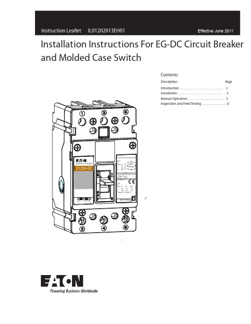
ContentsDescriptionPageIntroduction . . . . . . . . . . . . . . . . . . . . . . . . . . . . . . 2Installation . . . . . . . . . . . . . . . . . . . . . . . . . . . . . . . . 3Manual Operation . . . . . . . . . . . . . . . . . . . . . . . . . 5Inspection and Field Testing . . . . . . . . . . . . . . . . .6Installation Instructions For EG-DC Circuit Breaker and Molded Case SwitchInstruction Leafl et IL01202013EH01Installation I nstructions F or EG-DC Circuit B reakerand Molded Case SwitchEATON CORPORATION 1. IntroductionGeneral InformationIn this document, the term circuit breaker includes molded case switches. The E-frame Series G circuit breaker type ED-DC (Fig. 1) is rated 500 Vdc maximum and from 25A to 100A continuous current. (Refer to Table 1 for all available trip unit ratings.)The circuit breaker is listed in accordance with Underwriters Laboratories, Inc. Standard UL489. The type EG-DC circuit breaker is for use in grounded and ungrounded applications where multiple poles are connected in series (Figures 2-5)A 3-pole breaker may be wired as a 2-pole with ratedvoltage and interruption based on the number of poles wiredT able 1. Available C urrent Ratings.Circuit Breaker Types Current RatingsEG-DC253035404550607080Figure 2. Load Connected to Power Source. Grounded or Ungrounded Systems.WARNINGDO NOT ATTEMPT TO INSTALL OR PERFORM MAINTENANCE ON EQUIP-MENT WHILE IT IS ENERGIZED. DEATH, SEVERE PERSONAL INJURY OR SUBSTANTIAL PROPERTY DAMAGE CAN RESULT FROM CONTACT WITH ENERGIZED EQUIPMENT. ALWAYS VERIFY THAT NO VOLTAGE IS PRESENT BEFORE PROCEEDING WITH THE TASK, AND ALWAYS FOLLOW GENERALLY ACCEPTED SAFETY PROCEDURES.EATON IS NOT LIABLE FOR THE MISAPPLICATION OR MISINSTALLATION OF ITS PRODUCTS.The user is cautioned to observe all recommendations, warnings, and cautions relating to the safety of personnel and equipment as wellas all general and local health and safety laws, codes, and proce-dures.Figure 1. T ype EG-DC Series C DC Circuit BreakerThe recommendations and information contained herein are based on Eaton experience and judgement, but should not be considered to be all-inclusive or covering every application or circumstance which may arise. If any questions arise, contact Eaton for further information or instructions.Fixed Thermal90100in series. This instruction lea et (IL) gives procedures forinstallation and eld testing of the types EG-DC Series GDC circuit breaker.23Instruction LeafletInstallation I nstructions F or EG-DC C ircuit B reaker and Molded Case SwitchEATON CORPORATION Figure 3. Load Isolated from Power Source. Grounded orUngrounded Systems. If System Voltage Exceeds 300 Vdc, then Ungrounded Systems Only.Figure 4. Load Connected to Power Source. Grounded or Ungrounded Systems.Figure 5. Load Isolated from Power Source. Grounded orUngrounded Systems. If System Voltage Exceeds 125 Vdc, then Ungrounded Systems Only.PowerLoadPowerLoadBreaker Breaker 3 Pole3 PoleBreaker Load PowerBreaker LoadPower2 Pole2 PoleLoad Connected to Power Source.Fig. 5-3Breaker PowerLoad2 Pole2. InstallationThe installation procedure consists of inspecting the circuitbreaker and, as applicable, installing accessories, interphasebarriers and terminals, mounting the circuit breaker, connecting the line and load conductors, torquing terminals, and attaching terminal shields. Circuit breakers, accessories,mounting hardware, and unmounted terminals may be supplied in separatepackages. To install the circuit breaker, perform the following steps.If required, internal accessory installation in any type of circuit breaker should be done before the circuit breaker is mounted and 2-1. Make sure that the circuit breaker is suitable for theintended installation by comparing name-plate data with existing ratings and system requirements. Inspect the circuit breaker for completeness,and check for damage before mounting.2-2. Remove installed cover screws and cover.CAUTIONWHEN REMOVED AND REINSTALLED, THREAD-FORMING SCREWS WILL TRY TO REFORM THE THREADS IN THE BASE. CARE SHOULD BE TAKEN EVERY TIME A THREAD-FORMING SCREW IS USED TO ENSURE THE SCREW STARTS IN THE ORIGINAL THREADS. DAMAGED THREADS CAN RESULT IN IMPROPER CIRCUIT BREAKER COVER RETENTION.IL01202013E H014Instruction Leaflet IL01202013EH01Installation I nstructions F or E G-DC C ircuit B reakerand Molded Case SwitchEATON CORPORATION Figure 6. Cover Screw Installation Positions.2-5. If not already installed, mount terminals as shown in (Fig. 7).Figure 7. T erminal Installation.Terminal BreakerCollarT125EF TerminalWARNINGBEFORE MOUNTING THE CIRCUIT BREAKER IN AN ELECTRICAL SYSTEM, MAKE SURE THERE IS NO VOLTAGE PRESE NT WHERE WORK IS TO BE PERFORMED. SPECIAL ATTENTION SHOULD BE PAID TO REVERSE FEED APPLICATIONS TO ENSURE NO VOLTAGE IS PRESE NT. THE VOLTAGES IN ENERGIZED EQUIPMENT CAN CAUSE DEATH OR SEVERE PERSONAL INJ URY.NOTICEDEPENDING ON THE EQUIPMENT CONFIGURATION, THE CIRCUIT BREAKER CAN BE MOUNTED USING DIFFERENT STYLES OF HARDWARE. THE FOL-LOWING STEPS DESCRIBE HOW TO MOUNT THE CIRCUIT BREAKER USING STANDARD HARDWARE. WHEN SPECIAL HARDWARE IS NEEDED (FOR EXAMPLE, WITH THE ELECTRICAL OPERATOR), THE INSTRUCTION LEAFLET DESCRIBI NG THE ACCESSORY ALSO DESCRIBES THE SPECIAL MOU NTING ARRANGEMENTS.2-6. To mount the circuit breaker, perform the following steps:a. For individual surface mounting, drill mounting panel using the drilling plan shown in (Fig. 8). For panelboard mounting, only load end support mounting holes are required. For dead front cover applications, cut out cover to correct escutcheon dimensions.Figure 8. Circuit Breaker Mounting Bolt Drilling Plans and Escutcheon Dimensions.2-4. As shown in Figure 6, install secondary cover with screws (6 screws) and torque as speci ed in this gure.5Instruction Leaflet IL01202013EH01Installation I nstructions F or EG-DC Circuit B reaker and Molded Case SwitchEATON CORPORATION sories, make sure that accessory wiring can be reached when the circuit breaker is mounted.NOTICELABELS WITH ACCESSORY CONNECTION SCHEMATIC DIAGRAMS ARE PROVIDED O N THE SIDE OF THE CIRCUIT BREAKER. A NOTE SHOULD BE MADE OF THE DIAGRAMS IF THE LABELS CANNOT BE SEEN WHEN THE CIRCUIT BREAKER IS MOUNTED.d. Position circuit breaker on mounting surface.e.Install circuit breaker mounting screws and washers. TightenWHEN ALUMINUM CONDUCTORS ARE USED, THE APPLICATION OF A SUITABLE J OINT COMPOU ND IS RECOMMENDED TO REDUCE THE POSSIBILIT Y OF TERMINAL OVERHEATING. OVERHEATING CAN CAUSE NUISANCE TRIPPI NG AND DAMAGE TO THE CIRCUIT BREAKER.2-7. Connect line and load conductors and accessory leads.2-8. If required, install terminal shield on circuit breaker cover with mounting screws provided.2-9. After the circuit breaker is installed, check all mounting hard-ware and terminal connecting hardware for correct torque loading. Torque values for line/load terminals are given in Table 2 and on the circuit breaker nameplate.T able 2. Terminal T ypesTerminal Catalog Number Terminal Material Body Screw Head TypeAWG Wire RangeMetric Wire Range Wire Type Torque Valuelb-in (N.m.)T125EFSteelSlotted #14-3/0 2.5-95CuSeeNameplate3. Manual Operation and T hermal-Magnetic AdjustmentManual OperationManual operation of the circuit breaker is controlled by the circuit breaker handles and the PUSH-TO-TRIP button in the trip unit. The circuit breaker handle has three positions, two of which are shown on the cover with raised lettering to indicate ON and OFF . On the sliding handle barrier, ON, OFF , and trip. They are shown by a color-coded strip for each circuit breaker handle position: red for ON, white for tripped, and green for OFF , ON/OFF is also shown with the international symbols l/0 (Fig. 9Figure 9. Circuit Breaker Manual Controls.Circuit Breaker ResetAfter an automatic or accessory initiated trip, or a manual PUSH-TO-TRIP operation, the circuit breaker is reset by moving the circuitbreaker handle to the extreme OFF position.NOTICEIN THE EVENT OF A THERMAL TRIP IN A THERMAL MAGNETIC TYPE TRIP UNIT, THE CIRCUIT BREAKER CA NNOT BE RESET UNTIL THE THERMAL ELEMENT IN THE TRIP UNIT COOLS. NO CIRCUIT BREAKER SHOULD BE RECLOSED UNTIL THE CAUSE OF TRIP IS K NOWN AND THE SITUATION RECTIFIED.PUSH-TO-TRIP ButtonThe PUSH-TO-TRIP button checks the circuit breaker tripping func-tion and is used to periodically exercise the operating mechanism in thermal-magnetic trip units. The button is designed to be operated by a small screwdriver.).c. make poles in series conenctions as required for system (refer to g. 2-5).6Instruction Leaflet IL01202013EH01Installation I nstructions F or EG-DC C ircuit B reakerand Molded Case SwitchEATON CORPORATION 4. Inspection and Field T estingSeries G molded case circuit breakers are designed to provide years of almost maintenance-free operation. The following procedure describes how to inspect and test a circuit breaker in service.InspectionCircuit breakers in service should be inspected periodically. Theinspection should include the following checks (4-1 through 4-7):BEFORE INSPECTING THE CIRCUIT BREAKER IN AN ELECTRICAL SYSTEM, MAKE SURE THE CIRCUIT BREAKER IS SWITCHED TO THE OFF POSITION AND THAT THERE IS NO VOLTAGE PRESE NT WHERE WORK IS TO BE PERFORMED. SPECIAL ATTENTION SHOULD BE PAID TO REVERSE FEED APPLICATIONS TO ENSURE VOLTAGE IS PRESE NT. THE VOLTAGES IN ENERGIZED EQUIPMENT CAN CAUSE DEATH OR SEVERE PERSONAL INJ URY.CAUTIONMAKE SURE THAT CLEANING AGENTS OR SOLVENTS USED TO CLEAN THE CIRCUIT BREAKER ARE SUITABLE FOR THE J OB. SOME COMMERCIAL CLEANING AGENTS WILL DAMAGE THE NAME PLATES OR MOLDED PARTS.4-1. Remove dust, dirt, soot, grease, or moisture from the surface of the circuit breaker using a lint-free dry cloth, brush, or vacuum cleaner. Do not blow debris into circuit breaker. If contamination is found, look for the source and eliminate the problem.4-2. Switch circuit breaker to ON and OFF several times to be sure that the mechanical linkages are free and do not bind. If mechanical linkages are not free, replace circuit breaker.4-3. With the circuit breaker in the ON position, press the PUSH TO-TRIP button to mechanically trip the circuit breaker. Trip, reset, and switch circuit breaker ON several times. If mechanism does not reset each time the circuit breaker is tripped, replace the circuit breaker.4-4. Check base, cover, and operating handle for cracks, chipping, and discoloration. Circuit breakers should be replaced if cracks or severe discoloration is found.4-5. Check terminals and connectors for looseness or signs of over-heating. Overheating will show as discoloration, melting, or blister-ing of conductor insulation, or as pitting or melting of conductor sur-faces due to arcing. If there is no evidence of overheating or loose-ness, do not disturb or tighten the connections. If there is evidence of overheating,terminations should be cleaned or replaced. Before reenergizing the circuit breaker, all terminations and cable should be refurbished to the condition when originally installed.4-6. Check circuit breaker mounting hardware, tighten if necessary.4-7. Check area where circuit breaker is installed for any safety haz-types of chemicals can cause deterioration of electrical connections.Field TestingNEMA Standards.7Instruction Leaflet IL01202013EH01Installation I nstructions F or EG-DC C ircuit B reaker and Molded Case SwitchEATON CORPORATION Notes:E ective June 2011Instruction Leaflet IL01202013EH01Installation Instructions For EG-DC Circuit Breakerand Molded Case SwitchEaton CorporationElectrical Group1000 Cherrington ParkwayMoon Township, PA 15108United States877-ETN-CARE (877-386-2273)© 2011 Eaton CorporationAll Rights ReservedPrinted in USAPublication No. IL01202013EH01 Part No. IL01202013EH01June 2011PowerChain Management is a registered trademark of Eaton Corporation.All other trademarks are property of theirrespective owners.The instructions for installation, testing, maintenance, or repair herein are provided for the use of the product in general commercial applications and may not be appropriate for use in nuclear applica-to replace, amend, or supplement these instructions to qualify them for use with the product in safety-related applications in a nuclear facility.The information, recommendations, descriptions, and safety nota-tions in this document are based on Eaton’s experience and judg-al literature is published solely for information purposes and should not be considered all-inclusive. If further information is required, you should consult an authorized Eaton sales representative.The sale of the product shown in this literature is subject to the terms and conditions outlined in appropriate Eaton selling policies or other contractual agreement between the parties. This literature is not intended to and does not enlarge or add to any such contract. The sole source governing the rights and remedies of any purchaser of this equipment is the contract between the purchaser and Eaton. NO WARRANTIES, EXPRESSED OR IMPLIED, INCLUDING WARRANTIES OF FITNESS FOR A PARTICULAR PURPOSE OR MERCHANTABILITY, OR WARRANTIES ARISING FROM COURSEOF DEALING OR USAGE OF T RADE, ARE MADE REGARDINGTHE INFORMATION, RECOMMENDATIONS, AND DESCRIPTIONS CONTAINED HEREIN. In no event will Eaton be responsible to the purchaser or user in contract, in tort (including negligence), strict liability or otherwise for any special, indirect, incidental or conse-quential damage or loss whatsoever, including but not limited to damage or loss of use of equipment, plant or power system, costof capital, loss of power, additional expenses in the use of existing power facilities, or claims against the purchaser or user by its cus-tomers resulting from the use of the information, recommendations and description contained herein.E ective June 2011。
模具存放安全管理制度
第一章总则第一条为确保模具在生产、运输、存放过程中的安全,防止事故发生,保障员工生命财产安全,根据国家有关安全生产法律法规,结合我司实际情况,特制定本制度。
第二条本制度适用于公司所有模具的存放管理,包括模具的设计、制造、使用、维修、保养、报废等环节。
第三条模具存放安全管理应遵循“安全第一、预防为主、综合治理”的方针,确保模具存放安全。
第二章模具分类及存放要求第四条模具按以下类别进行分类:1. 按用途分类:冲压模具、注塑模具、压铸模具等;2. 按材料分类:钢模具、铝模具、铜模具等;3. 按精度分类:高精度模具、中精度模具、低精度模具等。
第五条模具存放要求:1. 模具应按照分类存放,不得混放;2. 模具存放区域应保持整洁、通风、干燥,防止模具生锈、变形;3. 模具存放架应稳固,承重能力符合要求;4. 模具存放时,应将模具放置在合适的支撑架上,避免因重力导致模具变形;5. 模具存放时,应避免与其他物品接触,防止碰撞、划伤;6. 模具存放区域应设有明显的警示标志,禁止非操作人员进入。
第三章模具存放管理职责第六条模具存放管理职责如下:1. 模具管理部门负责模具存放的总体规划和监督实施;2. 模具操作人员负责模具的日常存放和保养;3. 设备管理部门负责模具存放区域的设备维护和安全检查;4. 安全管理部门负责模具存放安全工作的监督和指导。
第四章模具存放安全措施第七条模具存放安全措施:1. 模具存放区域应配备消防器材,确保消防设施完好有效;2. 模具存放区域应定期进行安全检查,发现安全隐患及时整改;3. 模具存放人员应定期接受安全教育培训,提高安全意识;4. 模具存放区域应设置安全通道,确保人员在紧急情况下能够迅速撤离;5. 模具存放时,应确保模具与存放架之间的距离符合安全要求,防止因碰撞、挤压导致事故发生;6. 模具存放区域应定期进行防潮、防尘处理,确保模具存放环境良好。
第五章模具存放事故处理第八条模具存放事故处理原则:1. 事故发生后,立即停止作业,保护现场;2. 及时上报事故情况,启动应急预案;3. 对事故原因进行调查分析,制定整改措施;4. 对事故责任人进行责任追究。
- 1、下载文档前请自行甄别文档内容的完整性,平台不提供额外的编辑、内容补充、找答案等附加服务。
- 2、"仅部分预览"的文档,不可在线预览部分如存在完整性等问题,可反馈申请退款(可完整预览的文档不适用该条件!)。
- 3、如文档侵犯您的权益,请联系客服反馈,我们会尽快为您处理(人工客服工作时间:9:00-18:30)。
®
模具保护器
®
模具监控器在一个完整的成型周期内对所关心的模具型腔面进行两次拍照,即一检和二检,通常一检所选择的时机为型开刚刚完成,顶出动作还没有进行的时刻,这时的型腔多附有刚成型出的产品,即有品腔,这时拍照通常会检出所成型的产品是否不良,是否有留定模的产品;通常二检所选择的时机为顶出回退到位(不使用机械手时)或机械手已到安全区域且顶出回退到位,在合模动作还没有动作之前。
这时的模具型腔内不含有成型品,即无品腔,这时拍照会检出是否有未脱落的制品,还能帮助判断镶件、顶杆和滑块的位置或状态是否正常。
当一检失败时,会有报警灯提示,又可以加入不顶出的连锁保护,当二检失败时,也有报警灯提示,并指示注塑机不准合模,这样就有效地保护了模具,避免不必要的损失。
模具保护器工作原理:
模具保护器的安装方式:
安祺模具保护器,或模具监视器,又称模具电子眼,能有效保护价值昂贵的模具。
安
祺牌
安装实例图片:
系统功能特点:
1. 近红外(NIR)光线和摄像头结合技术解决了工厂四周环境光线明暗造成的潜在问题。
2. 可随生产的需要进行任意监测区域设定,可以应付多型腔及特殊镶件位置的监测;
3. 每个区域独立调整敏感度,适合深型腔及多穴的调整,避免误报警;
4. 软件精确定位,大大减少系统的误报警;
5. 可设置存储程序,进行多程序界面切换(换模无需调整参数);
6. 具有不良品输出信号,可以配合机械手及注塑机翻转阀以自动控制不良品的置放;
7. 具有监视区域放大功能,适合微型零件的生产监视及警报查看;
8. 提供统计和图像报告,并且这些数据可以直接从USB接口下载,以供模具维修时进行分析;
9. 监测结果可以手机短信的形式提供报警 (可选);
10. 脱离PC运行,保证了系统的稳定性。
应用范围 :
1.用于成型品留定模检
当有成型品留定模时,会在动模侧形成空穴,这空穴会被模具保护器觉察并报警。
2. 用于插件放置检测
当成型中有插件需要放置时,模具保护器会自动检测插件数量及位置是否正确。
3. 用于顶针或镶件断裂检测
顶杆或细小的镶件折断会对模具造成损伤或造成大的批次不良,模具保护器能洞察这一切,并能立即阻止合模,马上报警。
4. 用于滑块在位情况检测
开模后检查滑块是否回位,合模前检查滑块有无在位。
5. 用于填充不足的检测
填充不足现象发生时,会改变产品的形状或表面光泽。
6. 用于毛边的检测
有毛边出现时,产品会变大。
7. 用于落下不良检测
一次或几次顶出以后,仍有产品未脱落,这时合模是非常危险的,尤其是贵重的模具。
模具保护器能在这千钧一发之际大显身手、发出禁止合模指示,以防止损坏模具的事故发生。
8. 用于减少不必要的顶出次
有些注塑机有再次顶出功能,模具保护器能配合注塑机的这一功能,来减少顶出次数。
我们可以把顶出次数设定为单次或两次(本应该设定为更多次)经过顶出以后仍有未脱落的产品时,模具保护器会发出再次顶出指令,直至完全脱落再进行下一动作。
9. 用于生产线或组装线
可以完成部件的识别、选别或纠错任务,帮您实现自动化生产。
10.用于品质管理
可以把各个产品的标准样板存档,保存在控制器里,质检员可以实时地或者不定期地把现产品与样板比对,能既准确又及时地发现不良品。
操作界面示意图:
系统配置:
典型的模具保护器系统可以根据实际需要配置一个或多个检测头,系统硬件包括: (2)百万像素工业镜头、工业LED 光源等视觉器件;
(3)工控机:〉3.0G CPU,2048M 内存,160G硬盘,7”LCD显示器等。
(1)日本进口工业智能相机;
型号 mProtect‐1 mProtect‐2 mProtect‐3 mProtect‐4
监测功能 1.检测短射或废边产
品;
2.监视模具顶针、滑块
定位;
3.监视镶件产品的正确
位置;
4.落下不良检测;
1.检测短射或废边产品;
2.监视模具顶针、滑块定位;
3.监视镶件产品的正确位置;
4.落下不良检测;
5.对两个工位的复杂模具检测;
6.大型模具及动定模的特殊监
测;
1.检测短射或废边产品;
2.监视模具顶针、滑块定位;
3.监视镶件产品的正确位置;
4.落下不良检测;
5.对三个工位的复杂模具检测;
6.大型模具及动定模的特殊监
测;
1.检测短射或废边产品;
2.监视模具顶针、滑块定位;
3.监视镶件产品的正确位置;
4.落下不良检测;
5.对四个工位的复杂模具检测;
6.大型模具及动定模的特殊监
测;
相机数量 1台 2台 3台 4台
检测速度 <300ms/视场 <300ms/视场 <300ms/视场<300ms/视场光源 近红外(NIR)LED 近红外(NIR)LED 近红外(NIR)LED近红外(NIR)LED 光源模式 频闪 频闪 频闪频闪镜头 工业百万像素 工业百万像素 工业百万像素工业百万像素不良提示 2输入/2输出,图像保
存
2输入/2输出,图像保存 2输入/2输出,图像保存2输入/2输出,图像保存
PC配置 P43.0/2G内存17”触
模LCD显示器 P43.0/2G内存/17”触模LCD显
示器
P43.0/2G内存/17”触模LCD显
示器
P43.0/2G内存/17”触模LCD显
示器
界面切换程序 支持 支持 支持 支持 适应温度 ‐5℃-45℃ ‐5℃-45℃ ‐5℃-45℃ ‐5℃-45℃
通讯接口 RS-232
Ethernet连接
RS-232
Ethernet连接
RS-232
Ethernet连接
RS-232
Ethernet连接
适用范围 塑胶模具/金属模具 塑胶模具/金属模具 塑胶模具/金属模具 塑胶模具/金属模具 安祺模具保护器产品规格:。
