S350说明书(大)20100804B
SAJ三晶变频器S350系列说明书知识讲解

三晶变频器 S350 系列说明书(大)
仅供学习与参考
学习资料 仅供学习与参考
学习资料 仅供学习与参考
学习资料 仅供学习与参考
学习资料 仅供学习与参考
学习资料 仅供学习与参考
学习资料 仅供学习与参考
学习资料 仅供学习与参考
学习资料 仅供学习与参考
学习资料 仅供学习与参考
学习资料 仅供学习与参考
学习资料 仅供学习与参考
学习资料 仅供学习与参考
学习资料 仅供学习与参考
学习资料 仅供学习与参考
学习资料 仅供学习与参考
学习资料 仅供学习与参考
学习资料 仅供学习与参考
学习资料 仅供学习与参考
学习资料 仅供学习与参考
学习资料 仅供学习与参考
学习资料 仅供学习与参考
Hale Waihona Puke 学习资料 仅供学习与参考学习资料 仅供学习与参考
学习资料 仅供学习与参考
学习资料 仅供学习与参考
学习资料 仅供学习与参考
学习资料 仅供学习与参考
学习资料 仅供学习与参考
学习资料 仅供学习与参考
学习资料 仅供学习与参考
学习资料 仅供学习与参考
学习资料 仅供学习与参考
学习资料 仅供学习与参考
s350焊机英文说明书
Connect the front connector to the control cable of a wire feeder and connect the interface connector to control cable of a robot.
2.3 Wind Shielding and Ventilation For outdoor use or in cases where a fan is used, take wind protecting measures to prevent direct wind on the arc.
2.4 Required Power Supply Conditions and Cable Sizes The rated power supply voltage for this welder is three-phase 200/220V(AJ -Switch type), 220V(1E), 380V(2E), 415V(3E), 440V(4E).The welder supports a voltage compensation
(1) Connecting power supply Junctions should be securely insulated. See fig.2-1.
(2) Connecting blocks in the welder See fig.2-2. For CO2 gas or MAG gas arc welding , connect the base metal to the minus cable and connect the torch (wire) to the plus cable. (This is called reverse polarity or electrode positive.)
S350六方位介绍
一,车头1. 立标及品牌内涵2. 车辆的造型及气质3. 智能大灯4. 驻车定位系统5. 雨量感应式雨刮6. 红外大灯及车道保持功能二,车侧1.腰线及风阻2.后视镜3.自适应制动4.空气悬挂5.B柱钢材6.关门辅助级开门角度三,车尾1.尾灯2.倒车影像3.行李箱空间4.备用胎5.电动尾门四,后排1.空间2.座椅3.空调系统4.后座娱乐系统5.电动遮阳帘6.全景天窗五,驾驶室1.多功能方向盘2.行车电脑3.夜视系统4.定速巡航5.分屏显示6.导航系统NDE六,引擎室1.发动机2.溃缩区--贝拉博瑞尼3.隔音板4.注意事项,保养常识您好,我是欧龙奔驰的销售顾问XXX,很荣幸由我来为您介绍这款S350轿车,请问您贵姓?噢,X总,您看到的是我们S级的350车型,奔驰S级车型在他诞生之日起就备受瞩目,一直以来,都在引领豪华车的发展潮流,各界名流,各国政要,也多选择奔驰的S级轿车为座驾。
您看,这个三叉星辉标志也从来都是身份和地位的象征。
包括我本人,也以拥有一辆奔驰轿车作为我目前努力的目标。
从设计角度来看,这辆S350非常高贵优雅,很好的秉承并发扬了奔驰品牌的贵族血统,这个宽大的进气格栅配以鹰眼大灯,显得非常大气,而下面的这个LED日间行车灯,则在尊贵中增添了几分灵气。
当然,我们的大灯绝不是一种外在的摆设,这是目前最先进的智能大灯,在汽车大灯设计领域,复式氙气,随动转向,光线感应都已经普遍应用,而能称之为智能大灯的,只有我们奔驰一家。
因为我们这款大灯的输出功率是可以根据速度自动调节的,并在此基础上设计出了高速公路模式,乡村模式,主动转向照明,转角灯及增强型雾灯五种模式,可以适应各种路况。
另外,该车配备了驻车定位系统,前6个雷达探头,后4个,为您停车提供全方位的保护。
还有,您来看这边,我们为这辆车配备了间歇式无骨雨刮,它可以根据雨量自动调节,还有这边,红外线大灯及道路偏离警示系统,也为您的行车安全提供更多保障。
X总,您再来看这边,这辆S350的侧面设计同样高贵,给人一种优雅的享受。
荣威350用户手册(通用)

仪表和控制装置 ........................................................................................................................ 6 组合仪表 ................................................................................................................................... 7
喇叭......................................................................................................................................... 24
后视镜 ..................................................................................................................................... 25 电动外后视镜 ........................................................................................................................... 25 外后视镜折叠 ........................................................................................................................... 26 内后视镜 .................................................................................................................................. 26
S350大版说明书

S350系列
安全及注意事项
安全注意事项
安装、运行、维护或检查之前要认真阅读本说明书。 说明书中有关安全运行的注意事项分类成“警告”或“当心”。
警告 指出潜在的危险情况,如果不避免,可能会导致人身伤亡。
当心 指出潜在的危险情况,如果不避免,可能会导致人身轻度或中度的
伤害和设备损坏。这也可用来对不安全操作进行警戒。
SANJING INVERTER
S350
广州三晶电气有限公司 GUANGZHOU SANJING ELECTRIC CO.,LTD
电话:400 -678 -6091 网 址 :w w w . s a j b p . c o m
I nv er t e r
A-350.12
安全注意事项 概况
拆卸和安装 接线 操作
1
S350系列
第一章 概 况
第一章 概 况
1.1 变频器的综合技术特性
●输入输出特性 ◆输入电压范围:380V/220V±15% ◆输入频率范围:47~63Hz ◆输出电压范围:0~额定输入电压 ◆输出频率范围:0~600Hz ●外围接口特性 ◆可编程数字输入:6 路输入 ◆可编程模拟量输入:VI:0~10V输入,CI:0~20mA 输入 ◆开路集电极输出:1 路输出 ◆继电器输出:2 路输出(7.5kw以下 1 路输出,可扩展) ◆模拟量输出:2 路输出 FM 可选 0/4~20mA 或 0~10V,AM 0~10V(7.5kw以下只 有FM、AM需带扩展卡) ◆可编程高速脉冲HM1输入:1路输入0~50kHz ●技术性能特性 ◆控制方式:无 PG 矢量控制、V/F 控制、转矩控制 ◆过载能力:150% 额定电流 60s;180% 额定电流10s ◆启动转矩:无 PG 矢量控制(SVC):0.5Hz 150% ◆调速比:无 PG 矢量控制:1:100 ◆速度控制精度:无 PG 矢量控制:±0.5%最高速度 ◆载波频率:1.0k~15.0kHz ●功能特性 ◆频率设定方式:数字设定、模拟量设定、串行通讯设定、多段速、PID设定等。 ◆PID 控制功能 ◆多段速控制功能:16 段速控制 ◆摆频控制功能 ◆瞬时停电不停机功能 ◆自动电压调整功能:当电网电压变化时,能自动保持输出电压恒定 ◆提供多达 25 种故障保护功能:过流、过压、欠压、过温、缺相、过载等保护 功能。
奔驰S350保养复位

请[转]奔驰车回零解码新款奔驰ML350 W164机油保养灯回零-奔驰w1641、焚烧开关转到1档位置2、按压系统选择确认键S110s3直到仪表呈现A1p13呈现里程或温度呈现3、急剧按压里程复位按键A1s3 3次。
在呈现屏A1p13会呈现蓄电池信息4、按压进步/撤退键S110s1,直到呈现SERVICE MENU5、按压和-键S11正文:1、焚烧开关转到1档位置2、按压系统选择确认键S110s3直到仪表呈现A1p13呈现里程或温度呈现3、急剧按压里程复位按键A1s3 3次。
在呈现屏A1p13会呈现蓄电池信息4、按压进步/撤退键S110s1,直到呈现SERVICE MENU5、按压和-键S111s1,选择CONFIRMATION6、按压选择确认按键S110s3,选择COMPLETE SERVICE7、按压选择确认按键S110s3。
选择SERVICE CONFIRMED8、按压选择确认按键S110s3。
选择SERVICE MENU9、按压和-键S111s1,选择SPECIAL WORK10、按压选择确认按键S110s1 11、按压和-键S111s1,选择SERVICE 312、按压选择确认按键S110s3 13、按压和-键S111s1,选择OIL QUALITY 229.514、按压选择确认按键S110s3,A1p13呈现POSITION CONFIRMED15、按压选择确认按键S110s3。
A1p13呈现里程或温度16、封闭焚烧开关,保养回零结束。
.A1s3里程复位按钮A1p13仪表呈现区S110s3确认键S110s1进步/撤退键S111s1和-键奔驰W211轿车保养完毕后重设保养周期的方法如下:(1)将焚烧开关转到ON位置。
(2)一贯按↓或↑钮,知道呈现器上呈现保养呈现为止。
(3)按住仪表板上的R钮约5 s,在多效用呈现器上会呈现SERVICE MENU。
(4)按或-按钮。
选择CONFIRMATION。
LG 3D 眼镜 AG-S350 用户手册说明书

OWNER’S MANUALPlease read this manual carefully before operating and keep it for future reference.3D GLASSES AG-S350ENGLISH!NOTE ▶The pictures shown in this manual may differ from the actual appearances.3D GlassesNose Pad8-pin mini USB cableManual CDQuick Start GuidePouchesFEATURESAG-S350 are 3D glasses that use RF(2.4GHz) wireless communication.■If the device is connected to the TV that supports the RF glasses, you can enjoy the vivid 3D images. ■You can enjoy movies or pictures made as 3D.■If you are using your 3D glasses for the first time, make sure that the battery is fully charged.ACCESSORIESPART NAMESPairing 3D Glasses with Your 3D TV *1Pairing means establishing a wireless connection between the 3D TV and 3D glasses.If there is more than one TV in range, please place the 3D glasses within 10 cm of the 3D TV you want to pair the glasses with. The 3D glasses will pair with the 3D TV which has the strongest wireless signal.*1▶The device recognizes the unique ID of the TV to which it is connected. Thus, IDs of other TVs are not recognized by theCHARGING THE GLASSES1 Connect the USB port located under the power button on the glasses to the USB port of the TV or PC using the supplied 8-pin mini USB cable as shown by the fi gure.2Charge the glasses until the LED is green. The glasses will fully charge in about 1 hours 50 minute .3Battery life and charging time▶ 5 min charge : Approximately 7 hours ▶ 30 min charge : Approximately 40 hours※ Battery life may vary depending on the user’s environment.HOW TO WEAR THE 3D GLASSESENGLISH!NOTE ▶While charging: The LED is red.▶When charging is complete: The LED is green.▶When the battery is discharged: The Red LED blinks for 1 minute and turns off automatically. ▶The 3D glasses can still be used while charging via a USB device.CAUTION ▶ If you use a USB cable other the one (8-pin mini USB) supplied with the product, the product may be damaged.▶ This equipment shall be powered with USB 2.0 or higher.▶Avoid twisting or dropping the 3D glasses as this may cause damage or break them.Using 3D glasses may not be convenient for users wearing regular glasses. Adjusting the nose pad can improve your viewing comfort.USING 3D GLASSESHow to adjust the nose pad 1ENGLISH CAUTIONPlease read these safety instructions carefully toensure your personal safety and to prevent damage.1If you experience difficulty while viewing 3Dimages with the 3D glasses, you may havesome problems with your eyesight.2You may experience headaches or fatiguewhen viewing 3D images through the glassesfor too long.If you experience headaches, •• fatigue, ordizziness, stop watching immediately.3Do not drop objects onto the product orimport force to the product.This may result in electric shock or fire.4Do not use your product near a humidifier orkitchen counter.This may result in electric shock or fire.5Do not disassemble, repair or modify theproduct or its parts.Failing to do so may result in damage to theproduct or a malfunction.6The product may be easily taken off afterputting on for some people.7The following people should not use thisproduct: Pregnant women, infirm persons,persons with heart issues, as well as personsthat become nauseous easily.People with these conditions should notuse this product.8When watching 3D video, do not placeanything nearby that can be easily broken.You may mistake a 3D image for an actualobject and move your body, causing you tobreak nearby objects and hurt yourself.9Use this product for watching 3D video only.Do not use it for any other purpose.Do not use the 3D Glasses as sunglassesor reading glasses.10Do not spray cleaner directly onto the surfaceof the product.This may result in discoloration andcracks and may cause the screen displayto peel off.11Do not let water come into contact with theproduct when cleaning it. Ensure that waterdoes not enter the product.This may result in electric shock or fire.12Since the lens of the product is easilyscratched, make sure to clean the productwith a soft cloth.As the product may be scratched if thereis any foreign material on the cloth, makesure to shake off any dust before using it.13Do not scratch the surface of the Liquidcrystal shutters with a sharp tool and donot clean it using chemicals.14Do not apply force to the 3D Glasses’ Lenses.Do not drop or bend the product.15When watching 3D video, ensure that youare viewing the video within the specifiedreceiving range. (For more information, pleaserefer to the user manual of the TV.)If the receiving range is out of thespecified range, the screen may not beviewable as 3D video.16Flickering may be generated by the 3Dglasses (60 Hz) when watching the 3Dscreen when a magnetic fluorescent lamp(50 Hz) is on.If you encounter this symptom, please turnoff the light and continue watching.17The 3D glasses are a wireless communicationsdevice that use the 2.4GHz frequency bandand may be interfered by devices, such as themicrowave oven or the wireless LAN.Wireless performance may also be interferedwhen there is a physical barrier between the 3Dglasses and the 3D TV.18Children should be closely supervised whenusing the 3D glasses and should stop usingthem in the cases of fatigue, twitching of theeye or face muscles, or other involuntary move-ments.19Do not use the 3D glasses with the nose pad ifyou are not wearing regular glasses. Otherwise,this may hurt your eyes.TROUBLESHOOTINGSPECIFICATIONSENGLISHimprovement purposes.Class B ITE (Information Technology Equipment)This equipment satisfi es the EMC requirements and is intended for use in all environments, including thedomestic environment.Warranty Period1 year. (Europe :2 Years)If it proves to be defective with regards to the materials or workmanship under normal operating conditions during the warranty period, please contact the retailer where you purchased it. This war-ranty is only valid for the original purchaser of the product and is only effective locally.。
S350系列变频器用户手册
1
S350系列
第一章 概 况
第一章 概 况
1.1 变频器的综合技术特性
●输入输出特性 ◆输入电压范围:380V/220V±15% ◆输入频率范围:47~63Hz ◆输出电压范围:0~额定输入电压 ◆输出频率范围:0~600Hz ●外围接口特性 ◆可编程数字输入:6 路输入 ◆可编程模拟量输入:VI:0~10V输入,CI:0~20mA 输入 ◆开路集电极输出:1 路输出 ◆继电器输出:2 路输出(7.5kw以下 1 路输出,可扩展) ◆模拟量输出:2 路输出 FM 可选 0/4~20mA 或 0~10V,AM 0~10V(7.5kw以下只 有FM、AM需带扩展卡) ◆可编程高速脉冲HM1输入:1路输入0~50kHz ●技术性能特性 ◆控制方式:无 PG 矢量控制、V/F 控制、转矩控制 ◆过载能力:150% 额定电流 60s;180% 额定电流10s ◆启动转矩:无 PG 矢量控制(SVC):0.5Hz 150% ◆调速比:无 PG 矢量控制:1:100 ◆速度控制精度:无 PG 矢量控制:±0.5%最高速度 ◆载波频率:1.0k~15.0kHz ●功能特性 ◆频率设定方式:数字设定、模拟量设定、串行通讯设定、多段速、PID设定等。 ◆PID 控制功能 ◆多段速控制功能:16 段速控制 ◆摆频控制功能 ◆瞬时停电不停机功能 ◆自动电压调整功能:当电网电压变化时,能自动保持输出电压恒定 ◆提供多达 25 种故障保护功能:过流、过压、欠压、过温、缺相、过载等保护 功能。
1.3 变频器系列机型
变频器型号 输入电压
SR40G1 SR75G1 S1R5G1 S2R2G1 SR75G3 S1R5G3 S2R2G3 S004G3/5R5P3 S5R5G3/7R5P3 S7R5G3/011P3 S011G3/015P3 S015G3/018R5P3 S018R5G3/022P3 S022G3/030P3 S030G3/037P3 S037G3/045P3 S045G3/055P3 S055G3/075P3 S075G3/093P3 S093G3/110P3 S110G3/132P3
六方位绕车S350
六方位绕车介绍先生(女士)您好!我是庞大之星梅赛德斯-奔驰授权4S店的销售顾问XX,这是我的名片,很高兴为您服务。
我会从六个方位为您介绍这款车,这大约需要30分钟的时间。
如果您有任何疑问,可以随时打断我,我会为您做详细的介绍。
现在我们可以开始了吗?第一方位车辆正前方(车左前方45度)您现在看到的这款车是梅赛德斯奔驰S级轿车。
从车辆前端的这个角度我们会看到这款轿车的整体布局。
整车显得大气庄重。
全新的S级轿车更有肌肉感,凸显了它的力量和健美的线条。
独特的三叉星辉立标,象征着奔驰在海陆空三大领域机械化的卓越成就和广泛应用。
该车车宽1.871米。
前机盖的V型设计,象征着成功与荣耀,彰显了该车的稳重和大气,并且符合空气动力学的设计,风阻系数只有0.26。
家族传承的中网设计,让您能一眼就能认出它来。
前方的六个雷达传感器,在您停车时,为您提供很大的方便。
全新的复合式的氙气大灯就像人的双眼显得更加深邃,一路注视着前方,象征着我们的客户的高瞻远瞩,下方白色的LED日间行车灯增强了驾驶的安全性,也已经成为了奔驰家族的血统特征。
并且该车配备了智能照明系统(五种模式),它会随着路况,车速及方向盘转动自动来调节灯光的明暗,远近和左右。
一切都由车载电脑完成,您只需轻松驾驶就可以了。
您是否有相同的感受呢?如果您没有问题的话我们进入下一个方位。
第二方位车辆右侧在这方位我主要向你介绍梅赛德斯奔驰的安全和舒适(接下来,我们来到车的右侧)这款车的车长是5.23米,他的轴距更是达到了3.165米,在同级别中它是最长的,配上这样的肩线和腰线,再加上车窗周围的镀铬设计,给人稳重、时尚的视觉冲击。
打开前车门,您可以看到舒适的真皮座椅,非常柔软的座椅配以顶级的皮饰,并且座椅可以做多方位的调节,能够给乘客全方位的支撑,并且他是无压力座椅,他是一种记忆座椅,里面的填充物是管状物,不管什么身材的人坐都能形成很好的包裹性,做多久都不会变形,不会影响内饰的美观。
三晶变频器S系列说明书大
1
S350系列
第一章 概 况
第一章 概 况电压范围:380V/220V±15% ◆输入频率范围:47~63Hz ◆输出电压范围:0~额定输入电压 ◆输出频率范围:0~600Hz ●外围接口特性 ◆可编程数字输入:6 路输入 ◆可编程模拟量输入:VI:0~10V输入,CI:0~20mA 输入 ◆开路集电极输出:1 路输出 ◆继电器输出:2 路输出(7.5kw以下 1 路输出,可扩展) ◆模拟量输出:2 路输出 FM 可选 0/4~20mA 或 0~10V,AM 0~10V(7.5kw以下只 有FM、AM需带扩展卡) ◆可编程高速脉冲HM1输入:1路输入0~50kHz ●技术性能特性 ◆控制方式:无 PG 矢量控制、V/F 控制、转矩控制 ◆过载能力:150% 额定电流 60s;180% 额定电流10s ◆启动转矩:无 PG 矢量控制:0.5Hz/%(SVC) ◆调速比:无 PG 矢量控制:1:100 ◆速度控制精度:无 PG 矢量控制:±0.5%最高速度 ◆载波频率:1.0k~15.0kHz ●功能特性 ◆频率设定方式:数字设定、模拟量设定、串行通讯设定、多段速、PID设定等。 ◆PID 控制功能 ◆多段速控制功能:16 段速控制 ◆摆频控制功能 ◆瞬时停电不停机功能 ◆自动电压调整功能:当电网电压变化时,能自动保持输出电压恒定 ◆提供多达 25 种故障保护功能:过流、过压、欠压、过温、缺相、过载等保护 功能。
在某些情况下,甚至在
中所述的内容也会导致重大的事故。所以在
任何情况下要遵守这些重要的注意事项。
★
为了确保正确的运行而采取的步骤。
警告标记呈现在变频器的 上。 使用变频器时要遵守这些指导。
WARNING
Read the user manual before operation. Risk of electrical shock.Wait 10 minutes after removing power before servicing. Do not connect AC power to output terminals U/T1,V/T2 and W/T3.
G-S350SU绿色USB2.0 eSATA 3.5英寸硬盘外壳用户手册说明书
Green USB2.0/eSATA Combo Enclosure for 3.5” Serial ATA Hard Drivewith One-touch BackupG-S350SUUser’s ManualCONTENTSINTRODUCING GREEN USB2.0/ESATA3.5” Hard Drive ENCLOSURE 3 About this Guide3 System Requirements3 Package Contents4Safety Precautions 4HARDWARE BASICS6HARDWARE INSTALLATION710HARD DRIVE PARTITION andFORMAT PROCEDURES in PC WINDOWS 2000/XP/VISTA 12ONE-TOUCH BACKUP IN PC16Main Interface Screen 16Task Configuration 17Example of a backup task 18USB Connection for Mac 10Software Installation for PC 11Software Installation for Mac SATA Connection for MacOS X 10.2 and above 10SATA Connection for Windows 2000/XP/Vista 11USB Connection For Windows 2000/XP/Vista 11Frequently Asked Questions 20Introducing Green USB2.0/eSATA 3.5” Hard Drive EnclosureThank you for choosing the G-S350SU, a Green USB2.0/eSATA 3.5” SATA Hard Drive Enclosure with One-touch Backup. Its smart power management will power down the Hard Drive automatically after the Hard drive is idle for 5 minutes (or when it detects USB cable is disconnected). Since the enclosure drive maintains the presence in the system, users can still access the drive anytime they want to. The G-S350SU handles the drive power down and spin up seamlessly to save electricity and money, which makes it an environment-friendly Green product.The One-touch Backup button and included IniBackup software allows Windows 2000/XP/Vista users to backup their critical data easily and restore them quickly when needed. The One-touch Backup only supports USB connection under Windows environment. eSATA connection and Mac do not support One-touch Backup. However, the enclosure can still support a third-party backup software such as Apple Time Machine etc.About This GuideBefore you begin using the G-S350SU, be sure to read this manual in its entirety.This guide contains: Introducing Green USB2.0/eSATA 3.5” Hard Drive Enclosure Hardware Basics Hardware Installation USB connection for Mac USB connection for PC Hard drive partition and format procedure in PC One-touch backup in PCSystem RequirementsBased on SATA II, SATA I, USB2.0 and USB1.1 specifications the transfer rates are up to:SATA II- 3.0Gb/sSATA I- 1.5Gb/sUSB2.0 - 480Mb/sUSB1.1 - 12Mb/sG-S350SU can support the speed specification listed above, however its transfer rates are likely to be lower, and will vary depending upon the type of SATA and USB host controller, SATA Hard Drive and computer hardware.•Windows PC, Macintosh desktop or NoteBook computer with available eSATA and/or USB port •MacOS X 10.2 and above for SATA connection, MacOS 9.2 and OS X for USB connection •Windows 2000/ Windows XP/ Windows Vista •Pentium II/ compatible and above with 128MB RAM •Both SATAII host port and SATAII hard drive are required for SATAII transfer speed •USB2.0 host port is required for Hi-Speed USB2.0 transfer speedPackage ContentsThe G-S350SU package includes the followings:Green eSATA/USB2.0 3.5” Hard Drive EnclosureQuick Installation GuideThe software CD contains the manual and backup softwareUSB2.0 cableAC/DC adaptereSATA cable(optional)Safety PrecautionsON INSTALLATION1. To reduce the risk of fire or electric shock, do not expose this product to rain,water or moisture.2. Do not place any containers with liquids (drinking glass, flower vase, etc.) or containers with small metal parts (paper clips, etc.) on top of the unit.3. According to standard industry practice, surge protection is recommended for all telecommunications devices. Surge suppressors and/or line conditioning should be used on the input power supply.ON OPERATIONDo not move the chassis during operation. Doing so may cause a malfunction.Protect the unit from shocks and vibrations.Do not use the subsystem in areas exposed to oily smoke or steam, such as a kitchen or close to a humidifier.Do not use the subsystem in locations exposed to rain or splashes of water, such as outdoors, in a bathroom, or close to a window.Do not use the subsystem on an unstable or slanted surface without proper support.Do not expose the unit to direct sunlight or hot air where the temperature could exceed 45℃or very cold locations where the temperature is below 0℃.Keep the power cord away from hot appliances.Do not touch the power cord with wet hands.ON TRANSPORTATIONSave the packing materials as you may need to repack and transport the unit at a later date. Always remove the disc before moving the unit.ON POWER SOURCESWhen you are not using the unit for a long time, disconnect the power cord from the unit.To unplug the AC power adapter from the wall outlet, grasp the adapter itself. Do not pullthe cord.WarningIf any of the following conditions occur, immediately disconnect the power cord from the wall outlet and contact your dealer or an authorized service station. Continuing to use the computer involves the risk of fire and electric shock.•Smoke or unusual smell is coming from the subsystem.•Water has entered the unit, or the unit has become wet.• A foreign object has entered the unit.•The unit has been dropped or the front panel or frame has been damaged.•The power cable is damaged, causing wire breakage or exposed leads.Hardware BasicsPrecaution:Please make sure your hand is dry and remove static from your body by touching metal parts of your computer chassis.Power/One-touch Backup button:--- Back Panel--- 2 -6mm Screws --- 6 -5mm Screws --- 8 -4mm Screws --- Base Tray bridge--- Front Panel --- Base Tray --- Power/One-touch Backup button --- Enclosure Sleeve 1, Press and hold the button for 1 second to turn on the enclosure, LED turns to blue;2, While the enclosure is powered on and connected to the PC through USB cable, press the button for1 second to start the preconfigured backup task in IniBackup;3, To shut down G-S350SU, press and hold the buton for 3 seconds;4, The hard drive will spin down and enter sleep mode to save power automatically after 5 min idle.Hardware Installation1. Unscrew to loosen the Enclosure back panel. Remove the back panel.2. Use your figers to push the Base Tray out.Front PanelBack Panelk c a B t n o r F Note:The diagrams below are using the G-S350U Enclosure as an example.3. Pull the enclosure sleeve out from the Base Tray and place it aside.4. Align the black Power/SATA connector on the hard drive to the black female SATA connector on the Base plate bridge, and push the drive into the connector completely.5. Secure the HDD to the Base Tray with 2 hard drive screws.6. Push the Base Tray into the Enclosure Sleeve.7. Secure the Base Tray and Enclosure Sleeve with two 6mm screws.8. Plug the AC/DC adapter into the Enclosure, and connect the unit to your computer using a USBcable or eSATA cable. Then press the power button to turn it on.Software Installation for MacSATA Connection for MacOS X 10.2 and aboveG-S350SU has built in eSATA port for you to take advantage of high throughput performance. At the moment when this manual is written, none of Mac computers has built-in external SATA port accessible to connect G-S350SU enclosure. Current solution is to add a third-party Mac compatible PCI or ExpressCard to SATAII or SATAI host controller adapter with eSATA port or SATA port (with “L” shaped key type). When SATA port is available, please get a SATA cable with proper eSATA and/or SATA connectors on both ends to connect G-S350SU to your Mac, then follow steps below to use G-S350SU enclosure:1. When computer is powered off, attach G-S350SU to the SATA port of the computer.2. Turn on G-S350SU first, then power on your Mac.3. After Mac OS boots up, it will recognize it automatically, ask you to initialize the newdrive if it was not initialized yet, and mount the drive on desktop.Above described connection and power sequence is referred to as Hot Boot. There aretotal five power sequence modes by which an external hard drive can possibly be usedwith a computer system. They are defined as follows:Hot Boot – Computer is off, enclosure is on and is attached to computer. Boot up system.Cold Boot – Computer is off, enclosure is off and is attached to computer.Boot up system completely, then turn on the enclosure.Hot Plug – System is up and running, enclosure is turned on then attached to computer.Cold Plug – System is up and running, enclosure is off then attached to computer. Enclosureis turned on.Power Cycle – System is up and running, enclosure is on and mounted on the computer.Then,power off the enclosure, wait for several seconds and turn the enclosure back on.It is important to note that different SATA host adapters handle the power sequence in different way. Some support all five power sequence modes, the other can only support Hot Boot.G-S350SU supports all five power sequence modes. To find out what your SATA host adapteris capable of, please contact the manufacturer of SATA host adapter, or simply try all power sequence mode yourself.USB Connection for MacWhen the Enclosure is connected to the computer, MacOS X will recognize it automatically, initialize it (if the drive is not initialized) and mount the drive to desktop. All five power sequence modes are supported in USB connection. Note: MacOS X provides a Disk Utility to create multiple volumes, which is located in Utilities folder inside Applications folder.Software Installation for PCSATA Connection for Windows 2000/XP/ VistaSome PC computers nowadays are equipped with external SATA ports for peripheral connectivity,or provide a SATA cable and bracket to route internal SATA port on motherboard to external port. Otherwise, to take advantage of high performance SATA connection, you need to add a third-party SATA II or SATA I host controller adapter with external eSATA port or SATA port (with the “L” shaped key type). When external SATA port is available, please get a SATA cable with proper eSATA and/or SATA connectors on both ends to connect G-S350SU to your PC, and follow steps below to use G-S350SU enclosure:1. When computer is powered off, attach G-S350SU to the SATA port of the computer.2. Turn on G-S350SU first, then power on your PC.3. After Windows boots up, it will load the driver and recognize the enclosure automatically. If youdon’t see a new(SATA) drive in My Computer, probably the SATA drive needs to be partitionedand formatted first. Please refer to next section to partition and format the drive if necessary. Above described connection and power sequence is referred to as Hot Boot. There are total five power sequence modes, Hot Boot, Cold Boot, Hot Plug, Cold Plug, and Power Cycle, by which an external hard drive can possibly be used with a computer system. Please refer to the section “SATA Connection for MacOS X 10.2 and above” for definition.It is important to note that different SATA host adapters handle the power sequence in different way. Some support all five power sequence modes, the other can only support Hot Boot. G-S350SU supports all five power sequence modes. To find out what your SATA host adapter is capable of, please contact the manufacturer of SATA host adapter, or simply try all power sequence mode yourself.USB Connection For Windows 2000/XP/VistaWhen the enclosure is connected to the computer and power on, the system will start installing for the proper driver. Please follow the on-screen instruction to complete the driver installation.If you do not see the new drive letter added in My Computer after the driver finishes loading, the reason could be the hard disk such as a brand new one has no partition and format yet. In this case, please follow the procedures in next section to partition and format it before using.Hard Drive Partition and Format procedures in PC Windows 2000/XP/Vista:If a new hard disk icon dose not appear in “My Computer”, check device manager under system in the control panel. Then double click on “Disk Drives” to see if a new entry appears.If you can see a new entry as shown (Example, WDC WD80 OBB-32BSA0) above, you are ready to partition and format the drive.1. Open Control panel, “Administrative Tools” and “Computer management”.Step 22. Click on “Disk Management”.Step 33. “Write Signature and Upgrade Disk Wizard” windows will show up and click “Next”.Step 4 4. Write a signature to the new drive, click “Next”.Step 5 5. Click “Finish” to close the wizard.Step 66. Select the new “Unallocated” disk, and then right click to choose “Create partition”.Step 77. Follow the onscreen instruction to partition and fully format the drive.Note: If it assigns a new hard drive letter but format dose not run automatically, please exit “Computer Management”, and find the new drive letter in My computer and right click it to select format.One-touch Backup in PCAfter the drive is partitioned and formatted, it should mount as a new drive letter in the PC Windows 2000, XP or Vista. Next, insert the included CD into the system, locate and open a folder named G-S350SU, find and double click the ButtonManager.exe installation file, follow the on-screen instruction to complete the process. Restart the computer, you are ready to configure the backup task and use the One-touch Backup function as described next.Note:The One-Touch Backup function only works in USB connection under Windows PC.Main Interface ScreenPlease launch the IniBackup software, the following description of the program will help you to understand how to use it.Area 1 -- Task menu, listing all preconfigured backup tasks.Button 2 -- Open the task file previously saved.Button 3 -- Save the task list to a file *.iniBackup.Button 4 -- Display the drive property.Button 5 -- Add a new task.Button 6 -- Open a new list of task.Button 7 -- Delete the task selected.Button 8 -- Modify the setting of a task.Button 9 -- Execute all the tasks in the menu area.Button10 -- Exit the program.Area 11 -- It displays the path of auto-loading task file when the square box is checked, and One-touch Backup button is pressed.Task ConfigurationArea 1 -- Source Directory, to specify the file and folder path to backup/restore/copy from. Area 2 -- Destination Directory, to specify the destination path of the backup/restore/copy task. Option 3 – Active. If checked, the task will be executed when you execute the backup utility by pressing One-touch button or through the “Execute” icon in task list screen. Option 4 -- All Files including subdirectory will be in backup/restore/copy if checked. Option 5 – Newer. If checked, only new file will be saved in the backup compared with previous backup. Option 6 – Archive. If checked, only archive files will be copied. Option 7 -- Back up. If you choose the selection of “Backup”, the backup function will backup file system from source directory to target directory.Option 8 -- Restore. If you choose the selection of “Restore”, the restore function will restore file system from source directory to replace the existing files of target directory.Option 9 -- Copy. If you choose the selection of “Copy”, the copy function will copy file systemfrom source directory to target directory.12345689Example of a backup taskStep 11. Click the “Add” button in the IniBackup main screen.Step 22. Click the “Browse” buttons to set the path of source and destination.3. Configure the options and click OK.Step 3Step 44. Return to the main screen and then click the “Save” button to save the task to a file. Assign a name to the task file.Step 55. In the IniBackup main screen,(1), Open a task file previously saved;(2). Check the option “Loaded Task File” in order to launch this backup task automatically when One-touch button is pressed.(3). Exit the program.6. Press the front backup button for 1 second to start the backup.Frequently Asked QuestionsQ1,What are SATA,SATA I,SATA II,eSATA any way?How are they related to G-S350SU enclosure?A1: SATA stands for Serial ATA, in contrast to old Parallel ATA (IDE, EIDE, ATA and ATAPI) technology. SATA starts with 1.5Gb/s specification, and evolves to 3.0Gb/s specification, which is commonly referred to as SATA II. Hence, original SATA 1.5Gb/s is called SATA I to distinguish with SATA II 3.0Gb/s.Initially SATA was designed as an internal or inside-the-box interface technology for storage device like HDD. Both SATA I and SATA II hard drives use plug and receptacle interface with “L” shaped key as shown below.This connectors and cable(flat) with “L” shaped key support both SATA 1.5Gb/s and 3.0Gb/s, however the cable length is limited to 1m(around 3.3 feet) maximum.As shown above, it is more and more common to find a new type of SATA receptacle in the system or PCI/ExpressCard host card and plug(without “L” shaped key), called eSATA. eSATA becomes a standard for external SATA peripherals. Our G-S350SU has eSATA port built in. Depending on the type of SATA port you have in the computer, please get the proper SATA cable to connect them.Q2. How should I disconnect G-S350SU safely from the computer? After I disconnect the SATA enclosure, why does the drive icon still stay on the desktop of MacOS X?A2: In USB connection, in Windows PC, please click “Safely remove USB mass storage device –Drive letter” line inside Safely Remove Hardware icon on the System Tray; In Mac computer, please trash the external drive icon. Then disconnect G-S350SU from the system.In SATA connection, depending on the SATA host controller(and sometimes OS) you use, some controllers support hot plug and unplug function, some don’t. You have to find out its capability. To prevent data corruption, the safest way to disconnect SATA cable or power off G-S350SU isto shut down computer first.SATA drive (or SATA connection) is not treated essentially as removable device to the most of systems if not all. That is why there is no eject icon associated to SATA drive in Finder of Mac OS X, and System Tray in Windows has no Remove Hardware option for SATA drive. Therefore, when the SATA drive is connected, some system still keeps SATA drive icon, you just won’t be able to use the drive until you connect it back.Q3. How is SATA compared to USB and Firewire in speed? What performance gain can one expect by using SATA connection?A3: Following chart shows the specification data rate(MBps) and Overhead among USB, Firewire and SATA.Next table compares real world benchmark between USB,Firewire and SATA drives:Table: Comparison of interface speeds and data transferrates external disk drive interfacesAbove data are quoted from . The performance of G-S350SU in your application might be higher or lower depending upon the hard drive used, SATA and USB host and computer hardware. In our test, we have seen over 60MB/s sequential read and write speed in SATA connection. SATA is the better choice for storage device.。
s350_360_370_manual_v30
珠海施诺电力科技有限公司
1、产品标识及产品型号对照表
1.1、本说明书查阅方法
本说明书的内容主要是本公司产品的使用说明,随本公司产品一起提供给用户。 本说明书将几种系列的产品使用说明编撰在一起,叙述中没有特别指明型号的即为各 系列共同的部分;特别指明型号的叙述为该型号特有部分。 几种不同系列产品不同之处主要在于功能区别,需要了解各种功能的参数设置、试验 方法等内容时,首先按照产品标识的型号对照查阅“产品型号与功能对照表”,从对照表 上可以查到该型号所具备的功能。 对于一项具体的功能,如何设置参数、如何试验等使用方法可以从对应的章节查到, 按照查到的内容介绍,即可了解、掌握其使用方法。 用户也可以直接接通产品电源,按照产品人机界面显示的菜单名目,查找本说明书的 相关内容,从而达到了解、掌握产品使用方法的目的。
2、搬运、储存、开箱检查…………………………………..……..…5 3、安装……………………………………………………………….….……6 4、接线……………………………………………………………….….……7 5、端子图
5.1、S350 系列端子图…………………………..……………………8 5.2、S360 系列端子图…………………………..……………………9 5.3、S370 系列端子图……………………….......…………………10
●
●
●
●
●
●
●
●
●
●
●
●
●
●
●
●
●
●
●
●
●
●
驭胜S350导航4S店送(华阳)CE4K01212A通用机说明书
图标移动
按住单个图标 ( 约 1 秒 ),呈选中状态,拖动选中的图标到任意 ( 或另一个图标 ) 的位置, 此时图标位置移动 ( 或交换 ),便于用户对功能图标的重新排序。
218
基本操作
时间设置
1、轻触主桌面的 [ 设置 ] 图标。 2、轻触 [ 时间 ]。
将显示日期、时间模式、时间、关机时钟设置 菜单。
CDDA、CD+/-R、CD-RW、VCD、SVCD 将光盘插入光盘插槽,令印刷面朝上,播放将自动开始。
※ 提示 :本机不保证兼容所有碟片,只支持规格为 12CM 光碟,不支持 8CM 光碟。
弹出碟片
轻按面板上的 [ ] 键出碟。 光盘弹出后,本机将切换至光盘进入前的模式。
视频播放触摸按键分布
当播放图片或视频时,在屏幕上的功能区域分布如下图所示 :
手动调台
手动调台时,逐步选择频率。 轻触 [ ] 或 [ ] 图标,可以调到频率更高 / 更低的电台。
自动调台
长按 [ ] 或 [ ] 图标,自动搜索更高 / 更低的有效电台。
手动输入电台频率
1、轻触 [ ] ,进入数字键盘输入界面。 2、轻触数字以输入有效频率。 3、轻触 [OK ] 确认。
轻触 [ ] 清除输入的数字。
· 关机时钟 轻触 [ 关机时钟 ] 可设置为打开或关闭。
※ 提示 : ① 在设置界面下,用手拖动右侧的混动条可以上下移动设置菜单。 ② 设置完成后,轻触屏幕左上角可返回主桌面。
228
收音
进入收音机播放
进入主桌面,轻触的 [ 收音机 ] 图标,进入收音机模式。
※ 提示 :
① 如 当前播放的电台是立体声时,[ 立体声 ] 图标呈高亮,
· 设置日期
ABB ACS350 变频器 (0.37 ~ 18.5 kW) 说明书

ACS350用户手册ACS350变频器 (0.37~18.5kW)ACS350 变频器0.37~18.5kW用户手册3ABD00018670 版本D中文PDM:30020798BASED ON:3AFE68462401版本D英文生效日期: 2007-12-26©北京ABB 电气传动系统有限公司5安全须知概述本章介绍了在对变频器进行安装、操作和维护时必须遵守的安全须知。
如果忽视这些安全须知可能会造成人身伤亡或者变频器、电机或执行机构的损坏。
警告标志本手册中有下面两种警告标志:危险电压信号;可能会造成人身伤害或者设备损坏的高电压。
一般警告;除电之外的因素引起的可能会造成人身伤害或者设备损坏情况的警告。
安装和维修工作下面这些警告适用于需要对变频器、电机电缆或者电机进行安装和维护工作的人员。
警告!忽视下面这些警告可能会造成人身伤亡或者设备损坏。
只有具备资质的电气工程师才可以对变频器进行安装和维修!•通电情况下不能对变频器、电机电缆或者电机进行维修。
在断开电源后,对变频器、电机或者电机电缆进行检查和维修之前,必须等待至少5分钟,让变频器的中间直流电路电容器放电完毕。
通过用万用表测量的方法来确认(电阻至少为1MΩ):1. 变频器的输入U1, V1 和 W1 三相与地之间没有电压。
2. BRK+ 和 BRK- 端与地之间没有电压。
•在变频器或者外部控制电路通电时,不要对控制电缆进行任何操作。
即使变频器的电源已经切断,由外部电源供电的控制电路也会将危险电压引入变频器内部。
•不要对变频器或者变频器模块进行任何绝缘或者耐压测试。
注意:•当电源接通时,不管电机是否转动,在端子 U1、 V1、W1 、 U2、V2、W2 、BRK+ 和 BRK-上都会带有危险电压。
警告!忽视下面这些安全须知可能会造成人身伤亡或者设备损坏。
•变频器不是现场就能修复的。
不要企图在现场修复一台故障的变频器;请联系当地的ABB代表处或者授权的维修中心进行更换。
施耐德电气 350 360系列 电磁制动器 说明书
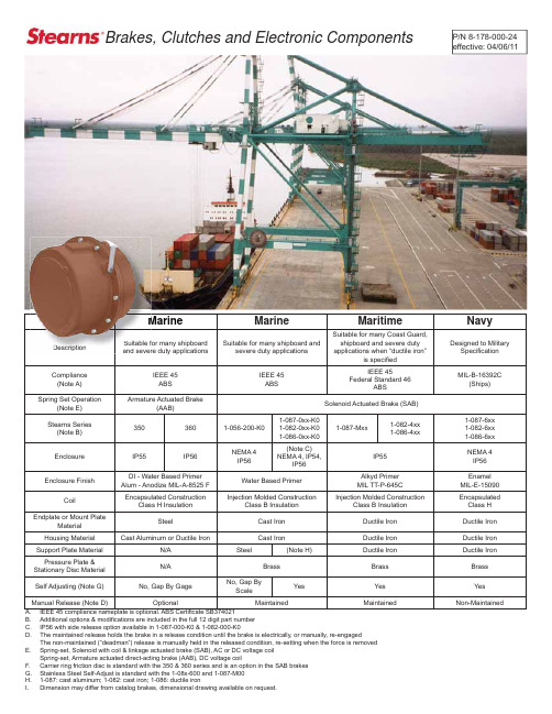
Brakes, Clutches and Electronic ComponentsP/N 8-178-000-24effective: 04/06/11Marine MarineMaritimeNavySuitable for many shipboardand severe duty applications Suitable for many shipboard andsevere duty applicationsSuitable for many Coast Guard, shipboard and severe duty applications when “ductile iron”is speci fi edDesigned to MilitarySpeci fi cationCompliance(Note A)IEEE 45ABSIEEE 45ABS IEEE 45Federal Standard 46ABSMIL-B-16392C(Ships)Spring Set Operation(Note E)Armature Actuated Brake(AAB)Solenoid Actuated Brake (SAB)Stearns Series (Note B)3503601-056-200-K01-087-0xx-K01-082-0xx-K01-086-0xx-K01-087-Mxx1-082-4xx 1-086-4xx1-087-6xx 1-082-6xx 1-086-6xx Enclosure IP55IP56NEMA 4IP56(Note C) NEMA 4, IP54,IP56IP55NEMA 4IP56Enclosure FinishDI - Water Based Primer Alum - Anodize MIL-A-8525 F Water Based Primer Alkyd Primer MIL TT-P-645CEnamel MIL-E-15090CoilEncapsulated ConstructionClass H InsulationInjection Molded ConstructionClass B InsulationInjection Molded ConstructionClass B InsulationEncapsulated Class H Endplate or Mount PlateMaterialSteelCast Iron Ductile Iron Ductile Iron Housing Material Cast Aluminum or Ductile IronCast IronDuctile IronDuctile Iron Support Plate Material N/A Steel(Note H)Ductile Iron Ductile Iron Pressure Plate & Stationary Disc Material N/ABrassBrass Brass Self Adjusting (Note G)No, Gap By GageNo, Gap By ScaleYes Yes Yes Manual Release (Note D)OptionalMaintainedMaintainedNon-MaintainedIEEE 45 compliance nameplate is optional. ABS Certi fi cate SB374021A. Additional options & modi fi cations are included in the full 12 digit part number B. IP56 with side release option available in 1-087-000-K0 & 1-082-000-K0C. The maintained release holds the brake in a release condition until the brake is electrically, or manually, re-engagedD.The non-maintained (“deadman”) release is manually held in the released condition, re-setting when the force is removed Spring-set, Solenoid with coil & linkage actuated brake (SAB), AC or DC voltage coilE. Spring-set, Armature actuated direct-acting brake (AAB), DC voltage coilCarrier ring friction disc is standard with the 350 & 360 series and is an option in the SAB brakes F. MDescriptionSuitable f and severBrake OperationSolenoid Actuated Brakes (SAB) are spring set power released brakes, acting through a solenoid and lever mechanism.The 1-087-x00, 1-082-x00 and 1-086-x00 series brakes are self-adjusting for friction disc wear.The endplate mounts to a C-face register & bolt circle, usually on the non-drive end of a motor. The brake hub is attached to the keyed shaft. The friction discs fi t closely onto the splined outside diameter of the hub. When the coil is de-energized, the spring pulls the lever arm about a pivot point. This action applies spring force against the pressure plate compressing the pressure plate and friction discs within the brake endplate. The disc pack, hub and shaft are unable to rotate. A small single-phase AC, or DC, solenoid coil is used with the design’s mechanical advantage to remove the spring force and allow shaft rotation. Coil pull in and holding amper-age requirements are listed in Stearns Catalog #200.Armature Actuated Brakes (AABs) are spring set power released direct acting brakes.The brake hub is attached to a shaft. A carrier ring style fric-tion disc fi ts closely to the outside diameter of the splined hub. The magnet body contains compression springs and an electrical coil. When electrical power is applied to the coil, the armature is drawn to the magnet body, the springs are compressed and the hub and friction disc are able to rotate. When electrical power is removed, the brake is spring set. The spring force moves the armature across a small preci-sion air gap to clamp the carrier style friction ring between the armature and the mount surface which prevents hub and shaft rotation. The AAB coil requires DC voltage which can be supplied by a DC power source or an AC recti fi er.Stearns brakes operate at the selected voltage and frequency. Wire separately for use with a variable frequency motor drive (VFD).Catalog brakes can be modi fi ed with additional modi fi cations for use in severe duty or industry speci fi c applications.The full product catalog #200, sizing and selection charts, installation and part information is available at .HubFriction & Stationary DiscsTorque SpringEndplateMagnetCoilAir Gap Hub StoppedNavy Brakes - built to the former MIL-B-16392CDuctile Iron Enclosure, brass stationary and pressure plates in the disc pack.SAB Style: Power released spring set brakeAdditional modi fi cations will change the eighth through twelfth character of the part number.Modi fi cation necessary for vertical above or below mount.Adapters available for other C-face mount requirements.The Master Plan details materials, construction and dimensional informationSeries Plan R633 Carrier Plan 1-087-600N1-1087-602-A N1-087-602-D 1-082-600N1-1082-602-A N1-082-602-C 1-086-600N1-1086-602-AN1-086-602-CWeapon and cargo elevators specifying MIL-E-17807B are constructed with bronze carrier ring style friction discs, ductile iron stationaryand pressure plates. Due to weight, the carrier rings are horizontal use only.Torque (lb-ft)Model Number*NEMA Frame SizeList Price1015253550751051-087-612-001-087-622-001-087-632-001-087-642-001-087-652-001-087-662-001-087-682-00182-256TC$8,925.00$8,975.00$9,050.00$9,200.00$9,500.00$10,000.00$10,700.001251752303304401-082-612-001-082-622-001-082-632-001-082-642-001-082-652-00324-405TC$19,100.00$19,350.00$19,850.00$20,450.00$21,350.0037050075010001-086-612-XO 1-086-622-XO 1-086-632-XO 1-086-642-XO 444-445TSC$27,500.00$27,500.00$29,000.00$30,500.0050075010001-086-662-XO 1-086-672-XO 1-086-682-XO505SC$27,500.00$29,000.00$30,500.00Obsolete Navy Brake Interchange ListStatic Torque (lb-ft)StyleObsolete Brake Model NumberNEMA Frame SizeObsolete Brake MasterPlanReplacement Brake ModelNumberStatic Torque (lb-ft)3NA-82-91-028-311-00182-256TC N1037-A NO Direct Replacement310NA-82A-91-028-321-00182-256TC 1-087-612-001015NA-82C-91-028-331-00182-256TC 1-087-622-001525NA-82B-91-028-341-00182-256TC 1-087-632-002535NA-84A-91-028-351-00182-256TC 1-087-642-003550NA-84B-91-028-361-00182-256TC 1-087-652-005075NA-86B-91-028-381-00182-256TC1-087-662-007590NA-1006B 1-021-111-00Special pre-NEMA Frame N1190ANO Direct Replacement ---135NA-1008B 1-021-121-00Special pre-NEMA FrameNO Direct Replacement---180NA-1304C-131-023-111-00324-405TC N322H 1-082-622-00175270NA-1306C-131-023-121-00324-405TC 1-082-642-00330360NA-1308C-131-023-131-00324-405TC 1-082-652-00440180NA-1304C-161-023-141-00444-445TSC N322H1-082-622-00 with adapter. See ordering Information175270NA-1306C-161-023-151-00444-445TSC 1-082-642-00 with adapter. See ordering Information 330360NA-1308C-161-023-161-00444-445TSC 1-086-612 the full part numberis a de-rated torquederated to 37010-1051-087-400182-256TC1-087-M0010-105Marine Duty Spring Set BrakeCast Iron Enclosure, brass stationary and pressure plates in the disc pack.SAB style: Power released spring set brake.Additional modi fi cations will change the eight through twelfth characters of the part number. Options are listed on the pamphlet back cover and in the catalog.Additional options and modi fi cations are recorded in the 8-12 position.Lb-Ft AC Part Number List Price DC Part Number List Price 31-056-212-K0$1,6751-056-216-K0$1,97561-056-222-K0$1,9901-056-226-K0$2,290101-056-232-K0$2,0951-056-236-K0$2,065151-056-242-K0$2,1951-056-246-K0$2,495201-056-252-K0$2,5301-056-256-K0$2,830251-056-262-K0$2,6251-056-266-K0$2,9251-056-200-K056TC - 145TC mount: 5-7/8” bolt circle, 4-1/2” register IP56 (close mount), NEMA 4X, side release Dimensional drawing side release 1-056-202-D1-087-000-K0182TC - 256TC mount: 7-1/4” bolt circle, 8-1/2” registerIP56 (close mount), NEMA 4 & 4X. IP56 with side release optionDimensional drawing pull release 1-087-002-D; side release: 1-087-002-ZDLb-Ft AC Part Number List Price DC Part Number List Price 101-087-012-K0$2,1251-087-016-K0$2,695151-087-022-K0$2,1751-087-026-K0$2,745251-087-032-K0$2,2501-087-036-K0$2,820351-087-042-K0$2,4001-087-046-K0$2,970501-087-052-K0$3,1501-087-056-K0$3,720751-087-062-K0$3,6501-087-066-K0$4,2201051-087-082-K0$4,8001-087-086-K0$5,3701-082-000-K0324TC - 405TC mount: 11” bolt circle, 12-1/2” register IP54, NEMA 4 & 4X. IP56 with side release optionDimensional drawing pull release 1-082-002-D; side release 1-082-002-ZDLb-Ft AC Part Number List Price DC Part Number List Price 1251-082-012-K2$8,8501-082-016-K2$10,4151751-082-022-K2$9,1001-082-026-K2$10,6652301-082-032-K2$10,2001-082-036-K2$11,7653301-082-042-K2$10,8001-082-046-K2$12,3654401-082-052-K2$12,3001-082-056-K2$13,8651-086-000-K0324TC - 405TC mount: 14” bolt circle, 16” register Cast Iron Enclosure, IP54, NEMA 4Dimensional drawing pull release 1-086-002-DLb-Ft AC Part Number List Price DC Part Number List Price 5001-086-022-K2$17,3001-086-026-K2$19,9257501-086-032-K2$19,5501-086-036-K2$22,17510001-086-042-K2$21,8001-086-046-K2$24,425Marine Duty Spring Set BrakeAAB: Armature Actuated Style Spring Set BrakesDuctile Iron Cover, DC Coil, IP56 Rating•Corrosion resistant fi nish over steel magnet body, armature and splined hub•Sizes range from 35 lb-ft to 300 lb-ft•Typical options listed on the pamphlet back cover•Rectifi ers are listed in catalog•The 350 & 360 series enclosures are rated IP56, NEMA 4. The magnet body and coil are designed as a Class H insulation system. No modifi cation for vertical use is needed. Selection is made through a series of material and construction choices and options. A full part number is provided after all specifi cations are considered. The AAB style brake has a long per-formance life when the small, precision air gap is properly maintained. Coil engage and release times are listed in the catalog. The 350 series is pressure plate mountedThe magnet body is farthest from the mount surface. The carrier ring style friction disc is close to the mount surface.Cover plugs are removed to reach the under-cover threaded retracting style maintained release bolts.Conduit box option•Mechanical status switch available•Six bolt adjustment by feeler gage•Viton fl at gasket between housing and pressure plate mount•Covers available in die cast aluminum or ductile iron•The 360 series is magnet body mountedThe magnet body is closest to the mount surface. The carrier ring style friction disc farthest from the mount surface. The fric-tion disc can be changed without removing the magnet body.External non-maintained release•Under-cover threaded retracting style maintained release bolts with optional external yoke release•Conduit box option•Mechanical status switch available•Longer hub with four set screws accepts larger•diameter shaftThree bolt adjustment by feeler gage•Viton O-ring between housing & pressure plate•mountCovers available in die cast aluminum or ductile•ironBasic SelectionThe full part number is assigned at purchase orderBore Size?•Torque Required?•Magnet Body Mount (360) or Pressure Plate Mount (350)•Mounting Dimensions: NEMA C-face or metric bolt circle?•Factory de-rate torque for longer wear life or due to shaft diameter?•AC voltage selection? Rectifi er choice will determine the DC coil voltage.•Conduit Box?•AAB Model Torque(lb-ft)Shaft Bore (Min/Max)(in / mm)List Price*350-6 350-7 350-8 350-917019623027835-6050-110100-180175-3001-1/8 - 1-3/81-3/8 - 1-5/81-5/8 - 1-7/81-7/8 - 2-1/830-3530-4835-4530-70$3,195 - $4,283$4,266 - $5,353$4,909 - $5,897$6,605 - $7,603360-6 360-7 360-8 360-917019623027822-6050-110100-180175-3001-1/8 - 1-5/81-3/8 - 1-7/81-5/8 - 21-7/8 - 2-3/830-4030-4835-5040-60$3,195 - $4,533$4,266 - $5,653$4,909 - $6,197$6,605 - $7,903* List Price varies by torque, mount, options, conduit box & external yoke releaseMaritime Duty Spring Set BrakeDuctile Iron Enclosure, brass stationary & pressure plates in the disc pack SAB style: Power released spring set brakeAdditional modi fi cations will change the eighth through twelfth character of the part number.Options are listed on the pamphlet back cover and in the catalog.All SAB brakes are rated for fi xed frequency & voltage. Wire separate from a variable frequency drive (VFD).Modify for vertical above or below use.1-087-M00182TC - 256TC mount: 7-1/4” bolt circle, 8-1/2” register IP56 (close mount), NEMA 4 and pull release Dimensional drawing: 1-087-M02-DLb-Ft Model Number List Price 101-087-M12-001-087-M16-00AC DC $4,332$4,762151-087-M22-001-087-M26-00AC DC $4,360$4,790251-087-M32-001-087-M36-00AC DC $4,416$4,846351-087-M42-001-087-M46-00AC DC $4,472$4,902501-087-M52-001-087-M56-00AC DC $4,560$4,990751-087-M62-001-087-M66-00AC DC $4,708$5,1381051-087-M82-001-087-M86-00AC DC$4,892$5,322The 1-087-400 is out of production.1-087-400 OD was 9.47 OD; the 1-087-M00 is 11.88 OD1-082-400324TC-405TC mount: 11” bolt circle, 12-1/2” register IP56 (close mount), NEMA 4 and pull release Dimensional drawing: 1-082-402-DLb-Ft Model Number List Price 1251-082-412-001-082-416-00AC DC $9,672$9,6721751-082-422-001-082-426-00AC DC $9,800$9,8002301-082-432-001-082-436-00AC DC $9,948$9,9483301-082-442-001-082-446-00AC DC $10,214$10,2144401-082-452-001-082-456-00AC DC$10,518$10,518500-1000 Lb-ft, see the 1-086-600 Navy series (page 7)Mount adapters are available for use with:182-256TC, 7-1/4” AJ Bolt Circle 284-286TC, 9” AJ Bolt Circle444-505TC, 14” AJ & 14.5” AJ Bolt CircleMount adapters are available for use with:56-145TC, 5-7/8” AJ Bolt Circle 284-286TC, 9” AJ Bolt Circle 324-405TC, 11” AJ Bolt CircleStainless Steel Spring Set BrakesSevere Wash Down Enclosure IP56, NEMA 4x SAB style: Power released spring set brake NEMA 56C to 145TC5-7/8” bolt circle (AJ), 4-1/2” register (AK)1-056-900 SeriesOptimum Corrosion Protection• NEMA 4x, IP56, IP57 rating with close couple mount • 300 Series stainless steel enclosure and hardware • Viton • ® gaskets and o-rings No exposed paint surface• Universal horizontal / vertical mount• External maintained side release rests with voltage application • Options list on the pamphlet back cover • Dimensional, inrush and amperage information available at • Non-Drive End Motor MountDimensional Drawing: 1-056-904-D Select torque, shaft bore, voltage Drive End Coupler MountDimensional Drawing: 1-056-904-5DSelect torque, 5/8 or 7/8 shaft & bore, voltage Nominal Static Torque lb-ft (Nm)Basic Model Number and List Price*AC AC List Price*DC DC List Price*3 (4)1-056-914-00$3,4251-056-916-00$3,7256 (8)1-056-924-00$3,4901-056-926-00$3,79010 (14)1-056-934-00$3,5951-056-936-00$3,89515 (20)1-056-944-00$3,6951-056-946-00$3,99520 (27)1-056-954-00$3,7801-056-956-00$4,08025 (34)1-056-964-00$3,8751-056-966-00$4,175Nominal StaticTorque lb-ft (Nm)TypeBasic Model Numberand List Price Wt. Lbs. (kg)3AC 1-056-71S-0X $2,47422 (10)6AC1-056-72S-0X$2,53922 (10)10AC 1-056-73S-0X $2,63922 (10)15AC 1-056-74S-0X $2,73922 (10)20AC 1-056-75S-0X $2,82422 (10)25AC1-056-76S-0X$2,91922 (10)5/8” or 7/8” shaft/bore size• (for 5/8”, use “05” in place of “0X” in model number)• (for 7/8”, use “07” in place of “0X” in model number)• Nominal Static Torque Lb-ft (Nm)No. of Friction DiscsCoil Size MaximumSolenoid Cycle Rate (1)Thermal Capacity (2)Inertia (Wk 2)AC DC cycles/min hp-sec/min (watts)Lb - Ft (kgm 2 x 10⁻⁴)AC DC Horizontal Vertical 3 (4)244+36109 (11.2) 6.5 (80).014 (5.88)6 (8)2K4K4+36109 (11.2) 6.5 (80).014 (5.88)10 (14)2K4K4+36109 (11.2) 6.5 (80).014 (5.88)15 (20)2K4+M4+36109 (11.2) 6.5 (80).014 (5.88)20 (27)3K4+M4+36109 (11.2) 6.5 (80).020 (8.40)25 (34)3M4+P4+36109 (11.2)6.5 (80).020 (8.40)Engineering Speci fi cations Hub SelectionCharacterBore (in.)Keyway** (in. x in.)A*B C D 5/85/83/47/81/8 x 1/163/16 x 3/323/16 x 3/323/16 x 3/32E F*K L*1-1/81-1/41/211/4 x 1/81/4 x 1/81/8 x 1/161/4 x 1/8N*O*P*R*S*9/1611/161-1/1613/1615/161/8 x 1/163/16 x 3/321/4 x 1/83/16 x 3/321/4 x 1/8(1) Maximum solenoid cycle rate is based on ambient temperature of 72ºF (22ºC) with 50% duty cycle. Does not relate to brake cycle rate (see Thermal Capacity).(2) Thermal capacity rating is based on ambient temperature of 72ºF (22ºC), stop time of one second or less, with no heat absorbed from the motor.In Line drive end coupler styleBetween two C-face registers C-face Mount - non-drive endStearns Division of Rexnord Industries, LLC, has over 60 years experience with supporting marine, maritime, drilling, port and similar severe duty applications. Many options and modifi cations are available to adapt the SAB and AAB style spring set brakes to meet your application. The following list are common severe duty options. These modifi cations can be added to the standard industrial or hazardous duty brakes as detailed in the Stearns catalog. Design, application and fi eld support is readily available by phone, fax or e-mail to talk about your specifi -cation and additional options or brake solutions.Option Application SAB AAB IEEE 45 nameplate Add to Marine brakes, standard on Navy & Maritime X XCoil: Encapsulated construction, Class H Insulation Robust construction for temperature extremes & high cycle rates. Class H isstandard in the AABSeePage 1StdSpace Heater Maintain a consistent temperature to reduce brake condensation and resultingcorrosionX X Carrier ring friction disc Weapons lift and extreme inertia loads X Std Hardware, external: StainlessMountOutdoor saltwater or vapor exposure X X Gasket: Brake to Motor Neoprene gasket for close couple IP 56/57 mount X X Epoxy or Enamel paint fi nish Enclosure corrosion, compare to spec page one X X Internal endplate fi nish Corrosion control in disc pack area X N/A Stainless steel hub Extreme corrosion environments X X Stainless steel self-adjustmechanismPage one, Note G. All steel self adjust is an option also (no synthetic bushing)X N/A Manual adjust only Disable the self adjust feature in 1-08X-000 series X N/A Terminal strip Simplify wiring and maintenance X N/A Conduit box External conduit box with terminal strip X X Status switch Set as normally open or closed to confi rm set or release X X Proximity switch Confi rm brake set or release X N/A Encoder mounted inside brake Non-standard shaft requirements, brochure available detailing this optionHousing machining for externalencoder mountRigidly attach or tether an encoder to the brake X XCarrier ring friction disc con-struction Extreme duty applications, horizontal only SeePage 1StdAdapters Adapt brake to a larger or smaller C-face mount X X Through shaft Through bore & seal in housing X X Manual release alternatives Maintained, non-maintained, full, under-cover X X Vertical mount Specify mount above or below the motor X N/ASpecifyBasic brake part number (enclosure •rating & torque)Shaft bore & keyway•Leadwire position•Options & modifi cations including •vertical above or below mount Information that would be useful in •selecting the correct brake Lead Wire PositionsPosition FormABCFG1231,2,32,3 BBCView facing brake mounting register. Rexnord Industries, LLCStearns Division5150 S. International DriveCudahy, WI 53110414-272-1100 Fax: 414-277-4364。
林肯电子Power Wave S350进阶过程焊接器说明书
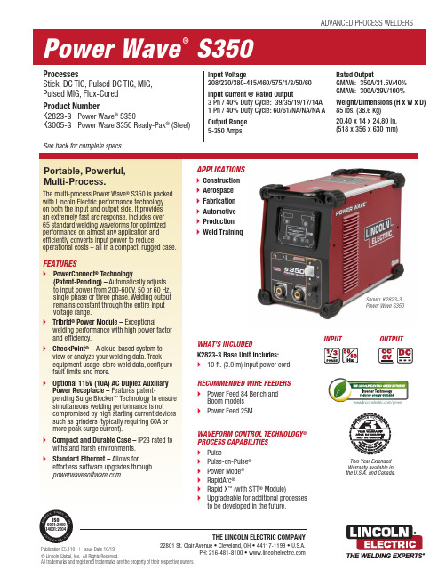
WHAT’S INCLUDEDK2823-3 Base Unit Includes:10 ft. (3.0 m) input power cordRECOMMENDED WIRE FEEDERSPower Feed 84 Bench andPower Feed 25MTHE LINCOLN ELECTRIC COMPANY22801 St. Clair Avenue • Cleveland, OH • 44117-1199 • U.S.A.PH: 216-481-8100 • © Lincoln Global, Inc. All Rights Reserved.All trademarks and registered trademarks are the property of their respective owners.ADVANCED PROCESS WELDERSProcessesStick, DC TIG, Pulsed DC TIG, MIG, Pulsed MIG, Flux-CoredProduct NumberK2823-3 Power Wave® S350K3005-3 Power Wave S350 Ready-Pak® (Steel) See back for complete specsInput Voltage208/230/380-415/460/575/1/3/50/60Input Current @ Rated Output3 Ph / 40% Duty Cycle: 39/35/19/17/14A1 Ph / 40% Duty Cycle: 60/61/NA/NA/NA AOutput Range5-350 AmpsRated OutputGMAW: 350A/31.5V/40%GMAW: 300A/29V/100%Weight/Dimensions (H x W x D)85 lbs. (38.6 kg)20.40 x 14 x 24.80 in.(518 x 356 x 630 mm)INPUT OUTPUT/greenWAVEFORM CONTROL TECHNOLOGY®PROCESS CAPABILITIESPulse-on-Pulse®(with STT® Module)Upgradeable for additional processesto be developed in the future.LI NC OL N E L E C TR ICTwo Year ExtendedWarranty available inthe U.S.A. and Canada.Shown: K2823-3Power Wave S350[ 2 ] | Power Wave S350To tap into the Power Wave S350 Stick, TIG and CV MIG process capability withouta Power Feed ® series wire feeder, add the K3001-2 S-Series User Interface Kit. This optional interface provides full control of welding parameters from the front panel of the power source for Stick and TIG processes.When used with a Power Feed series wire feeder, the feeder is typically used forcontrolling the system and the K3001-2 S-Series User Interface Kit meters can be used for viewing amps and volts. Kit also includes 12-pin Universal Remote Receptacle and TIG Gas Solenoid.FRONT1. Optional S-Series User Interface (K3001-2) for Stick,TIG and CV MIG with voltage sensing feeder 2. Status Light 3.Thermal Fault Indicator Light4. Tweco ®-Style Cam-Lock Output Terminals5. Optional Output Control Receptacle – 12-pin (included with K3001-2 S-Series User Interface)6. Work Sense Lead Receptacle7. Main Power Switch8.Reversible HandlesBACK9. 115V (10 Amp) AC Duplex Auxiliary Power Receptacle and Circuit Breaker(Optional - Order K2829-1 Kit)10. Arc L ink ® Welding System Component Communication Cable Receptacle 11. Circuit Breaker12. Sync Tandem/STT ® Receptacle 13. Input Power Cable Connection 14. TIG Solenoid Kit Knockout (optional TIG Solenoid included with K3001-2 S-Series User Interface) 15. Ethernet Cable Receptacle 16.Reversible Handles1234567910111213141516• Volts/Amps Control – Adjust volts in MIG and Flux-Cored welding or adjust amperage in Stick or TIG welding.• Welding Mode – Select the stick, TIG or CV wire process.• Advanced Process Options – Control pre- and post-weld settings to optimize arc starts and stops.• Arc Control – Adjust arc characteristics to match individual preferences.Reversible handles shownThe S-Series User Interface Kit allows control over:GENERAL OPTIONSWireless Connectivity Module Simple and secure machineconnectivity solution for monitoring and control capabilities without the hassle of costly network cables. Order K4352-1S-Series User Interface Kit This kit allows local control of stick, TIG and wire processes from the power source control panel. Includes TIG Solenoid and Remote Control Connector. Order K3001-2115V Auxiliary KitAdd a duplex 115V receptacle to the back of the machine. Includes PC board and harness which must be installed. Order K2829-1Inverter and Wire Feeder Cart Rear-wheeled cart with frontcasters and gas bottle platform. Convenient handles allow for easy cable storage. Small footprint fits through 30 in. (762 mm) door. Not intended for use with double head wire feeders. Order K3059-4Dual Cylinder Inverter & Wire Feeder CartRear-wheeled cart with frontcasters and dual cylinder platform. Convenient handles allow for easy cable storage. Small footprint fits through 30 inch (762 mm) door. Order K3059-5Tweco Style Cam-Lock Adapter Plug for Work & Electrode CablesCable plug for 2/0 (50 mm 2) cable. Order K2946-1Work Voltage Sense Lead Kit Required to accurately monitor voltage at the arc.Order K940-25 for 25 ft. (7.6 m) Order K1811-50 for 50 ft. (15.2 m)Order K1811-100 for 100 ft. 30.5 m)LC-40Tweco-Style Plug (male, 1/0 Thru 2/0) Order K3416-70LC-40Tweco-Style Receptacle (female, 1/0 Thru 2/0) Order K3417-70LC-40HDTweco-Style Plug (male, 3/0 Thru 4/0) Order K3416-90LC-40HDTweco-Style Receptacle (female, 3/0 Thru 4/0) Order K3417-90Deluxe Adjustable Gas Regulator & Hose KitAccommodates CO 2, Argon, or Argon-blend gas cylinders. Includes a cylinder pressure gauge, dual scale flow gauge and 4.3 ft.(1.3 m) gas hose. Order K586-1Power Wave S350 | [ 3 ]Power Wave S350 Ready-Pak (for Steel)• P ower Wave S350 Power Source (K2823-3)• P ower Feed 84 Wire Feeder (Bench Model) (K3328-13)• .035 in. (0.9 mm) Drive Roll and Split Wire Guide Kit (KP1505-035S)•M agnum ® PRO Curve ™ 400 Gun and Cable Package (K2952-2-10-45)• W ork Lead and Wire Feeder Power Source Cables Package – 350 amps, 60% duty cycle with Tweco style Cam-Lock connectors and Ground Clamp (K1803-2)• I nverter and Wire Feeder Cart (K3059-4)Ready-Pak PackagesReady-Pak packages are assembled and shipped on one pallet. Welding wire and shielding gas must be ordered separately.maintaining a high power factor and efficiency.generation. It also features 100Mbps Full Duplex Ethernet to support Lincoln Electric’s CheckPoint.Rugged ReliabilityTested under severe conditions:• Extreme Temperature Ranges • Extreme Humidity • Rain• Dirt and Dust• IP23 Rated PerformanceCheckPointCheckPoint, cloud server-based and mobile delivery solutions, is the welding industry’s most advanced weld data collection and monitoring tool, allowing fabricators to analyze their welding operations and processes. These tools can provide necessary data for customer ISO, Six Sigma, statistical process control (SPC), quality cost delivery (QCD), overall equipment effectiveness (OEE) and lean manufacturing efforts. CheckPoint is offered at no charge with every Power Wave purchase.RECOMMENDED ACCESSORIESShown:K1811-100General Options Continued Cool Arc 55 Water CoolerDesigned to integrate with Power Wave S350 and S500 power sources to cool water-cooled welding guns or torches rated up to 500 amps. Recommended for and hand-held MIG, TIG and Plasma cutting operations. 115V/1/60. The 55 S model includes an ArcLink communication flow sensor that detects water flow to prohibit welding when no flow is present. Order K3086-1 for Cool Arc 55 Order K3086-2 for Cool Arc 55 S STICK OPTIONSAccessory KitComplete kit for stick welding. Includes 30 ft. (9.1 m) electrode cable, 25 ft. (7.6 m) work cable, headshield, work clamp and electrode holder.Order K875 for 150 amps Remote Output Control with 12-pin Universal Connector Permits remote adjustment of output. Requires K3001-1 Stick/TIG User Interface.Order K857-2 for 25 ft. (7.6 m)12-pin to 6-pin AdapterAllows older 6-pin remote controls (K870, K963-3, K857) to be used with 12-pin Universal Connection. Order K2909-1TIG OPTIONS PTA-26FV 200 Amp Air-Cooled TIG Torch Order K1783-11 for 12.5 ft. (3.8 m) length, 1-cable. With Tweco-style adapter.Foot Amptrol ™ with12-pin Universal Connector Provides 25 ft. (7.6 m) of remote current control for TIG welding. Requires K3001-2 S-Series User Interface Kit. Order K870-2Parts KitsMagnum Parts Kits provide all the torch accessories you need to start welding. Parts kits provide collets, collet bodies, a back cap, alumina nozzles and tungstens in a variety of sizes, all packaged in an easy to carry reclosable box. Order KP508 for PTA-17 Order KP509 for PTA-26Hand Amptrol ™ with12-pin Universal Connector Provides 25 ft. (7.6 m) of remote current control for TIG welding. Requires K3001-2 S-Series User Interface Kit. Order K963-4Tweco Style TIG Torch Adapter Allows a one-cable TIG Torch to connect to the machine’s Tweco style output terminal. Order K960-3WIRE FEEDER OPTIONS Work and Wire Feeder 2/0 Weld PackageIncludes Tweco-style Cam-Lock connectors, work clamps, 15 ft. (4.5 m) work cable and 10 ft. (3.0 m) electrode cable. Rated 350 amps, 60% duty cycle. Order K1803-2Magnum PRO AL Air-Cooled & Water-Cooled Push-Pull Guns The Magnum PRO AL gooseneck style guns are designed to optimize a push-pull welding operation for aluminum. Uses Magnum PRO MIG Gun expendables. Available in 7-pin and 12-pin connections. Request Publication E12.14Power Wave STT Module This module allows easy connection and fast digitalcommunication with compatible Power Wave S-Series powersources, Power Feed wire feeders, and compatible water coolers. Add STT capability without having to purchase a second power source.Order K2902-1 US/Int’l (shown) Order K2921-1 CEPower Wave Advanced Module Provides multi-process reverse polarity (DC+), straight polarity (DC-), AC, high frequency TIG and STT functionality. Compatible with Power Wave S350 and S500.Order K2912-1C U S T O M E R A S S I S T A N C E P O L I C YThe business of The Lincoln Electric Company is manufacturing and selling high quality welding equipment, consumables, and cutting equipment. Our challenge is to meet the needs of our customers and to exceed their expectations. On occasion, purchasers may ask Lincoln Electric for information or advice about their use of our products. Our employees respond to inquiries to the best of their ability based on information provided to them by the customers and the knowledge they may have concerning the application. Our employees, however, are not in a position to verify the information provided or to evaluate the engineering requirements for the particular weldment. Accordingly, Lincoln Electric does not warrant or guarantee or assume any liability with respect to such information or advice. Moreover, the provision of such information or advice does not create, expand, or alter any warranty on our products. Any express or implied warranty that might arise from the information or advice, including any implied warranty of merchantability or any warranty of fitness for any customers’ particular purpose is specifically disclaimed.Lincoln Electric is a responsive manufacturer, but the selection and use of specific products sold by Lincoln Electric is solely within the control of, and remains the sole responsibility of the customer. Many variables beyond the control of Lincoln Electric affect the results obtained in applying these types of fabrication methods and service requirements. Subject to Change – This information is accurate to the best of our knowledge at the time of printing. Please refer to for any updated information.(1) Based on the U.S. National Electrical Code(2)On 230 Volt / 1 Phase inputs, the peak rating is at a duty cycle of 30%, except for GTAW processes (3)On 208 Volt inputs, the maximum output is limited to 300 ampsFor best welding results with Lincoln Electric equipment, always use Lincoln Electric consumables. Visit for more details.Shown: Cool Arc 55 S。
S350X烤箱使用说明书
切勿在安装烤箱时抬起烤箱门。 在打开烤箱门时,应避免用力过猛。
6.3 烤架烹调法 功能选择项目 温度调节范围
250℃
可以使食物迅速着色。建议将平底锅放在最高层的导轨上。如果是在短时间内 烤制少量食物,应将格栅放在由下面数第四层导轨上。如果是长时间使用烤架 进行烤制,应根据食物的体积将其放在最底部的导轨上。
防止烤箱内的蒸汽造成任何问题,应分两步将烤箱门打开:先半开(大约 5 厘 米)4 到 5 秒钟,在完全打开。尽可能快速的将食物取出,以免烤箱门打开,使 烤箱内部温度降低而影响食物的口味。
4.2 冷却系统 该烤箱装有冷却系统,并在烤箱开始工作后自动进入工作状态。 风扇将使空气稳定地从烤箱门的上方排出。排气在烤箱关闭后还将会继续持续 较短的时间。
2.3 炉灶面与烤箱间的连接方法 在安装完毕后,炉灶面应与烤箱间相连。在安装烤箱时,应预留足够空间,以 便顺利完成后面的操作。 按如图所示,将炉灶面的地线(黄-绿)与烤箱的接地端相连。 将炉灶面插头插入烤箱顶盖内适当的插座。确保接头的颜色和标志与烤箱插
座相符。 如果炉灶面装有余热指示器插头,必须将其插入右侧的活动插座。 现在将烤箱整个放入橱柜中;并确保电源线放在适当位置且不与烤箱的零部件 相接触。烤箱的零部件会在工作过程中变热。
在每次烤箱使用完毕后,注意检查控制旋钮总是处于零档位(关闭状态)。
不要在烤箱中放任何易燃物品:如果发生意外,可能导致起火。
在工作过程中,烤箱的温度会不断升高。注意不要触摸烤箱内部的发热装置。
CCD00000183759-2-橡胶金属装置——【动车组 CRH380B 用户手册】

1用途/功能 (5)2说明/操作 (6)2.1引言 (6)2.2使用条件/技术数据 (6)2.3技术说明 (7)2.3.1使用寿命和控制 (7)2.3.2抗介质腐蚀性 (7)2.3.3防火要求 (8)3操作和运行监控 (9)4安装和调试 (10)4.1运输/装运/储存 (10)4.1.1运输/装运 (10)4.1.2储存 (10)4.1.3储存后重新调试 (11)4.2安装 (12)4.3调试 (12)4.4维护 (12)4.4.1维护级 (12)4.4.2维护工作安排 (13)4.4.3检查 (13)4.4.4检修 (15)4.4.5维护说明 (16)4.5故障排除、更换概念/维修 (17)4.5.1故障排除 (17)4.5.2拆除 (17)4.5.3更换概念 (17)4.5.4拆卸 (24)4.5.5维修 (24)4.5.6组装 (24)4.5.7重新安装 (24)4.5.8设置和公差 (24)4.5.9清洁/喷漆 (25)4.5.10重启/功能试验 (25)4.6专用工具清单 (25)4.7处理 (25)5注有图解的零件清单(“LIP”) (26)6补充文件 (26)6.1软件文件 (26)6.2DP 硬件文件 (26)6.3安全数据表 (26)6.4批准文件 (26)7附录 (26)7.1缩写列表 (26)1用途/功能下面说明为使用橡胶-金属连接部件和天然橡胶制作的模制橡胶部件的通用指南。
此外,该说明也适用于部分为塑料的金属部件。
这些说明是按照标准 DIN 7716 (ISO 2230-1973) 编制,同时其通用条件也适用于合成橡胶制品。
2说明/操作2.1引言多数橡胶制品在不良储存条件或处理不当时物理属性将改变;由于过度硬化,软化,长期变形及脱皮,牵伸或其他表面性损坏造成不能使用。
臭氧、光、热、湿气、溶剂的影响或压力下存储也会使橡胶制品发生损坏。
橡胶部件正确储存和处理的情况下,其特性几年之内不会改变。
