AUX W6001联通版终端参数信息
实验三EZVoice6001电话互通配置实验

eBridge通信实验指导书(VOIP部分)深圳市讯方通信技术有限公司二零零七年八月实验三EZVoice 6001网关的应用一、实验目的:掌握VOIP业务基本原理,能够用WEB方式对VG设备基本业务进行调试,实现电话互通。
二、实验器材:EZV oice 6001语音网关若干台网线若干米串口调测线若干根PC若干台电话机若干部三、实验内容说明:基本组网图四、基本规划:⑴本实验可以把EZV oice 6001分成多组进行实验,每两台EZVoice 6001 一组。
每台设备只能设置一个号码,本次实验以一组为例,其它组号码可以自行规划。
⑵学生机1号EZV oice 6001 W AN口地址为:129.9.0.101 ,号码设置为8880001。
⑶学生机1号EZV oice 6001 WAN口地址为:129.9.0.102 ,号码设置为8880002。
说明:学生机1号至学生机40号的EZV oice 6001设备WAN口地址分别已设置为129.9.0.101-129.9.0.140。
学生做实验时只需登入WAN口地址就可以。
五、实验步骤:A、1号学生机EZVoice 6001的配置1、设置1号学生机的EZV oice 6001,先启动浏览器(建议使用IE4.0及以上版本),在地址栏中输入IP地址“129.9.0.101”,回车后出现登入界面。
2、用户可以在【用户名】和【密码】栏输入相应的用户名和密码,按【登录】按钮,就能进入主页面并对设备进行配置。
(默认登录用户名为admin和登录密码为123456。
)3、登入后,系统信息页面为用户提供EZVoice 6001语音网关基础的系统信息。
4、在左边菜单中选择【WAN口配置】,WAN口是上行端口,在设备后面板上标有WAN的网线插口。
在左边的菜单中用鼠标选择【WAN配置】,配置界面如下:(此处的WAN口地址已经修改过,不需要在进行配置)5、在左边的菜单中用鼠标选择【通道配置】,将出现如下所示界面,通道号默认选择1,通道别名就是需设置得号码8880001,其它选项选择默认,然后单击修改。
设备选型及主要性能技术指标

支持3级RRU级联
设备重量
< 25 kg
模块功率
双射频模块联接时
8/8/8* @每载频15W
12/12/12* @每载频10W
单射频模块联接时
1/1/1 @每载频60W
2/2/2 @每载频30W
3/3/3 @每载频20W
4/4/4 @每载频15W
6/6/6 @每载频10W
安装方式
室内模块堆叠摆放/壁挂安装
工作环境
作温度-35~+55摄氏度
1、单小区最大24载波,单站点最大72载波
2、最大配置为S24/24/24
频段支持
支持GSM 900,1800频段
连接方式
光纤接口连接系统模块,实现无馈线安装
级联级别
支持6级RRU级联,最大拉远距离40Km
机柜外形尺寸
高×宽×深:700mm×600mm×480mm(不含底座)
设备重量
APM30H:<76.5kg(不包括用户设备)
交流输入
输入电压
176V AC~290V AC
输入电压频率
50Hz/60Hz
输出电压
-48V DC
直流输出
直流输出路数
20A:6路
12A:2路
4A:2路
安装方式
室内模块堆叠摆放/壁挂安装
工作环境
-40℃~+50℃
在-20℃以下的环境里,需要配置交流加热器。
1.1.2
厂家名称
诺西
基站型号
NSN FlexiBTS Product Description
最大频数
1、1 … 6扇区
2、多达24载波/BCF
3、运用多重BCF特征,能同步多达9个BCF
金笛MG35 4频段工业级GSM GPRS MODEM商品说明书

公司介绍产品零缺陷,售后零服务。
不需要服务的产品才是更好的产品。
缺图01金笛是一家集硬件、软件研发、生产、销售一体的高科技企业,注册资金2000万元,产品行销海内外,业内享有极高的美誉度。
MU-106M1806-NC5M1806-ME MG301-FT MC323RS232MC323MG301M1206B-FTMG35-FT M1806-NC5M1806-ME M1806N-NC5MG35-N M1806N-ME MG301-N小一体机MN1604大一体机MN1408RJ45M1206BMG35产品概述03把方便留给客户,把麻烦留给我们。
能简单才不简单。
提供高可靠的短信软硬件,立志把可靠性做到极致。
产品经过十多年的技术积累和积淀,不断迭代升级,日趋完善。
产品选型图02金笛MG35是一款全球4频段工业级GSM/GPRS MODEM,是一款2G短信猫。
金笛MG35 GSM/GPRS Modem其工作频段是GSM850MHz,EGSM900MHz,DCS1800MHz,PCS1900MHz。
提供GSM短信,GPRS数传业务,可在全球大多数国家使用。
该产品采用射频基带一体化超小超薄核心芯片方案,具有超低功耗、超宽温度、更快的速度传输率,抗干扰能力强。
经过雷击、浪涌、电脉冲、温度冲击、跌落、盐雾等大量可靠性测试,可靠性达到99.99%,是短信监控、报警、通知和M2M应用的理想方案。
超小超薄核心芯片金笛MG35核心模块采用强劲的ESD保护,直接放电空气±10KV,接触±5KV,充分的FLASH保护机制和多重防呆机制,保证设备可以长期稳定运行。
强劲ESD保护金笛MG35网络兼容性强,发送速度快,另有基站定位、空中升级固件等专利技术,价格却比较亲民,有着超高性价比。
超高性价比串口款USB口款做高性能的短信猫金笛GSM MODEM MG35典雅、端庄,如同一件精致的艺术品,七分圆润三分刚硬每一个细节的品性、品质,都经过严格测试与检测,把可靠性做到极致外壳采用铝合金材质,防刮防指纹,坚固耐用磨砂工艺,高端时尚,质感十足USB款MG35产品配件您可能有这样的经历,插机箱前的USB不识别,插机箱后的USB就正常。
德力西9600变频器说明书(第二版)
前言感谢您选用德力西(杭州)变频器有限公司生产的CDI 9600系列小功率矢量变频器。
在使用CDI9600系列小功率矢量变频器之前,请您仔细阅读本手册,以保证正确使用。
不正确的使用可能会造成变频器运行不正常、发生故障或降低使用寿命,乃至发生人身伤害事故。
因此使用前应认真阅读本说明书,严格按说明使用。
本手册为标准附件,务必请您阅读后妥善保管,以备今后对变频器进行检修和维护时使用。
本手册除叙述操作说明外,还提供接线图供您参考。
如果您对本产品的使用存在疑难或有特殊要求,可以联系本公司各地办事处或经销商,当然您也可以直接致电我公司总部客户服务中心,我们将竭诚为您服务。
本手册包含0.75kW~5.5kW功率等级的CDI9600系列小功率矢量变频器使用说明,内容如有变动,恕不另行通知。
开箱时,请认真确认以下内容:1、产品在运输过程中是否有破损,零部件是否有损坏、脱落,主体是否有碰伤现象。
2、本机铭牌所标注的额定值是否与您的订货要求一致,箱内是否包含您订购的机器、产品合格证、用户操作手册及保修单。
本公司在产品的制造及包装出厂方面,质量保证体系严格,但若发现有某种检验遗漏,请速与本公司或您的供货商联系解决。
警告未经书面许可,不得翻印、传播或使用本手册及其相关内容,违者将对所造成的损害追究法律责任。
目录前言第一章安全运行及注意事项 (1)第二章产品信息 (3)2.1 铭牌数据及命名规则 (3)2.2 技术规范 (4)2.3 CDI9600系列小功率矢量变频器 (6)2.4 外型及安装尺寸 (7)2.5 日常使用的保养与维护 (8)第三章变频器的安装及接线 (12)3.1 变频器前盖与数字操作键盘的安装 (12)3.1.1 变频器前盖的安装 (12)3.1.2 数字操作键盘的安装 (12)3.2 安装地点及空间的选择 (13)3.3 安装地点及空间的选择 (15)3.3.1 主回路输入侧的接线注意事项 (15)3.3.2 主回路输出侧的接线注意事项 (16)3.3.3 主回路输出侧的接线注意事项 (18)3.4 控制电路的接线 (20)3.4.1控制电路端子排列及接线图 (20)3.4.2 控制电路端子的功能 (22)3.5 接地 (24)第四章键盘操作与运行 (25)4.1 操作方式的选择 (25)4.2 试运行及检查 (25)4.2.1 试运行前的注意事项及检查 (25)4.2.2 试运行 (26)4.2.3 运行时的检查 (26)4.3 键盘的操作方法 (27)4.3.1 键盘按键及功能 (27)4.3.2 键盘显示方式 (27)4.3.3 查看/设定参数的方法(用数字键盘) (29)4.3.4 键盘设定频率的方法 (30)第五章功能参数表 (31)第六章功能参数说明 (47)6.1 基本功能参数P00组 (47)6.2 辅助功能参数P01组 (64)6.3 输入输出端子与多段速运行功能P02组 (78)6.4多段速运行功能P03组 (97)6.5 其他功能参数P04组 (106)6.6 显示功能参数P05组 (110)第七章故障排除 (111)7.1 故障的诊断与排除措施 (111)7.2 报警显示和解释 (113)7.3 电机故障和排除措施 (113)附录RS-485通讯协议修正 (115)第一章 安全运行及注意事项CDI9600系列小功率矢量变频器安装、运行、维护和检查之前要认真阅读本说明书。
毛斯(Moxa)UC-8200系列双核ARM Cortex-A7 1GHz IIoT网关产品说明书
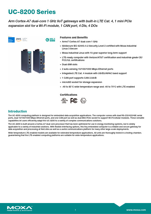
UC-8200SeriesArm Cortex-A7dual-core1GHz IIoT gateways with built-in LTE Cat.4,1mini PCIe expansion slot for a Wi-Fi module,1CAN port,4DIs,4DOsFeatures and Benefits•Armv7Cortex-A7dual-core1GHz•ISASecure IEC62443-4-2Security Level2certified with Moxa IndustrialLinux3Secure•Moxa Industrial Linux with10-year superior long-term support•LTE-ready computer with Verizon/AT&T certification and industrial-grade CE/FCC/UL certifications•Dual-SIM slots•2auto-sensing10/100/1000Mbps Ethernet ports•Integrated LTE Cat.4module with US/EU/APAC band support•1CAN port supports CAN2.0A/B•microSD socket for storage expansion•-40to85°C wide temperature range and-40to70°C with LTE enabledCertificationsIntroductionThe UC-8200computing platform is designed for embedded data acquisition applications.The computer comes with dual RS-232/422/485serial ports,dual10/100/1000Mbps Ethernet ports,and one CAN port as well as dual Mini PCIe socket to support Wi-Fi/cellular modules.These versatile capabilities let users efficiently adapt the UC-8200to a variety of complex communications solutions.The UC-8200is built around a Cortex-A7dual core processor that has been optimized for use in energy monitoring systems,but is widely applicable to a variety of industrial solutions.With flexible interfacing options,this tiny embedded computer is a reliable and secure gateway for data acquisition and processing at field sites as well as a useful communications platform for many other large-scale deployments.Wide temperature LTE-enabled models are available for extended temperature applications.All units are thoroughly tested in a testing chamber, guaranteeing that the LTE-enabled computing platforms are suitable for wide-temperature applications.AppearanceUC-8210UC-8220SpecificationsComputerCPU Armv7Cortex-A7dual-core1GHzDRAM2GB DDR3LSupported OS Moxa Industrial Linux1(Debian9,kernel4.4),2027EOLMoxa Industrial Linux31(Debian11,kernel5.10),2031EOLSee /MILStorage Pre-installed8GB eMMCExpansion Slots MicroSD(SD3.0)socket x13OS is selectable via Moxa Computer Configuration System(CCS)for CTO models.For the model names,see the Ordering Information section of thedatasheet PDF file.Computer InterfaceEthernet Ports Auto-sensing10/100/1000Mbps ports(RJ45connector)x2 Serial Ports RS-232/422/485ports x2,software selectable(DB9male) CAN Ports CAN2.0A/B x1(DB9male)Digital Input DIs x4Digital Output DOs x4USB2.0USB2.0hosts x1,type-A connectorsWi-Fi Antenna Connector UC-8220Models:RP-SMA x2Cellular Antenna Connector UC-8220Models:SMA x2GPS Antenna Connector UC-8220Models:SMA x1Expansion Slots UC-8220-T-LX:mPCIe slot x2UC-8220-T-LX US/EU/AP Models:mPCIe slot x1SIM Format UC-8220Models:NanoNumber of SIMs UC-8220Models:2Buttons Programmable buttonTPM TPM v2.0Ethernet InterfaceMagnetic Isolation Protection 1.5kV(built-in)Security FunctionsHardware-based Security TPM2.0Hardware Root of Trust Secure BootIntrusion Detection Host-based Intrusion DetectionSecurity Tools Security Diagnostic ToolSecurity Event AuditingSecure UpdateDisk Protection LUKS Disk EncryptionRecovery One-step recovery to the last known secure stateDual-system design with automatic failbackReliability Network Keep AliveNetwork Failover and FailbackSerial InterfaceBaudrate300bps to921.6kbpsData Bits7,8Stop Bits1,2Parity None,Even,Odd,Space,MarkFlow Control RTS/CTS,XON/XOFFADDC(automatic data direction control)for RS-485RTS Toggle(RS-232only)Console Port1x4-pin header to DB9console portRS-232TxD,RxD,RTS,CTS,DTR,DSR,DCD,GNDRS-422Tx+,Tx-,Rx+,Rx-,GNDRS-485-2w Data+,Data-,GNDCAN InterfaceNo.of Ports1Connector DB9maleBaudrate10to1000kbpsIndustrial Protocols CAN2.0ACAN2.0BIsolation2kV(built-in)Signals CAN_H,CAN_L,CAN_GND,CAN_SHLD,CAN_V+,GNDDigital InputsConnector Screw-fastened Euroblock terminalDry Contact Off:openOn:short to GNDIsolation3K VDCSensor Type Wet contact(NPN)Dry contactWet Contact(DI to COM)On:10to30VDCOff:0to3VDCDigital OutputsConnector Screw-fastened Euroblock terminalCurrent Rating200mA per channelI/O Type SinkVoltage24VDC nominal,open collector to30VDCCellular InterfaceCellular Standards LTE Cat.4Band Options US Models:LTE Band2(1900MHz)/LTE Band4(1700MHz)/LTE Band5(850MHz)/LTE Band13(700MHz)/LTE Band17(700MHz)UMTS/HSPA850MHz/1900MHzCarrier Approval:Verizon,AT&TEU Models:LTE Band1(2100MHz)/LTE Band3(1800MHz)/LTE Band5(850MHz)/LTE Band7(2600MHz)/LTE Band8(900MHz)/LTE Band20(800MHz)UMTS/HSPA850MHz/900MHz/1900MHz/2100MHzAP Models:LTE Band1(2100MHz)/LTE Band3(1800MHz)/LTE Band5(850MHz)/LTE Band7(2600MHz)/LTE Band8(900MHz)/LTE Band28(700MHz)UMTS/HSPA850MHz/900MHz/1900MHz/2100MHzReceiver Types GPS/GLONASS/GalileoState-of-the-art GNSS solutionAccuracy Position:2.0m@CEP50Acquisition Hot starts:1.1secCold starts:29.94secSensitivity Cold starts:-145dBmTracking:-160dBmTime Pulse0.25Hz to10MHzLED IndicatorsSystem Power x2Programmable x1SIM card indicator x1Wireless Signal Strength Cellular/Wi-Fi x6Power ParametersNo.of Power Inputs Redundant dual inputsInput Voltage12to48VDCPower Consumption10WInput Current0.8A@12VDCReliabilityAlert Tools External RTC(real-time clock)Automatic Reboot Trigger External WDT(watchdog timer)Physical CharacteristicsDimensions UC-8220Models:141.5x120x39mm(5.7x4.72x1.54in)UC-8210Models:141.5x120x27mm(5.7x4.72x1.06in)141.5x120x27mm(5.7x4.72x1.06in)Weight UC-8210Models:560g(1.23lb)UC-8220Models:750g(1.65lb)Housing SECCMetalIP Rating IP30Installation DIN-rail mountingWall mounting(with optional kit)Environmental LimitsOperating Temperature-40to70°C(-40to158°F)Storage Temperature(package included)-40to85°C(-40to185°F)Ambient Relative Humidity5to95%(non-condensing)Shock IEC60068-2-27Vibration2Grms@IEC60068-2-64,random wave,5-500Hz,1hr per axis(without USB devicesattached)Standards and CertificationsEMC EN55032/35EN61000-6-2/-6-4EMI CISPR32,FCC Part15B Class AEMS IEC61000-4-2ESD:Contact:4kV;Air:8kVIEC61000-4-3RS:80MHz to1GHz:10V/mIEC61000-4-4EFT:Power:2kV;Signal:1kVIEC61000-4-6CS:10VIEC61000-4-8PFMFIEC61000-4-5Surge:Power:0.5kV;Signal:1kV Industrial Cybersecurity IEC62443-4-1IEC62443-4-2Hazardous Locations Class I Division2ATEXIECExCarrier Approvals VerizonAT&TSafety UL62368-1EN62368-1Green Product RoHS,CRoHS,WEEEMTBFTime UC-8210-T-LX-S:708,581hrsUC-8220-T-LX:650,836hrsUC-8220-T-LX-US-S/EU-S/AP-S:528,574hrs Standards Telcordia(Bellcore)Standard TR/SRWarrantyWarranty Period5yearsDetails See /warrantyPackage ContentsDevice1x UC-8200Series computerDocumentation1x quick installation guide1x warranty cardInstallation Kit1x DIN-rail kit(preinstalled)1x power jack6x M2.5mounting screws for the cellular module Cable1x console cableDimensions UC-8210UC-8220Ordering Information12UC-8210-T-LX-SDefault:MIL1(-Debian9),2027EOLOrder WithModel UC-8210-T-LX-S(CTO):MIL3(Debian11)Secure/Standard,2031EOLWith MIL3Secure1GHzDual CoreBuilt in––-40to85°CUC-8220-T-LXDefault:MIL1(-Debian9),2027EOLOrder WithModel UC-8220-T-LX(CTO):MIL3(Debian11)Secure/Standard,2031EOLWith MIL3Secure1GHzDual CoreBuilt in Reserved Reserved-40to70°CUC-8220-T-LX-US-SDefault:MIL1(-Debian9),2027EOLOrder WithModel UC-8220-T-LX-US-S(CTO):MIL3(Debian11)Secure/Standard,2031EOLWith MIL3Secure1GHzDual CoreBuilt inUS region LTEmodulepreinstalledReserved-40to70°CUC-8220-T-LX-EU-SDefault:MIL1(-Debian9),2027EOLOrder WithModel UC-8220-T-LX-EU-S(CTO):MIL3(Debian11)Secure/Standard,2031EOLWith MIL3Secure1GHzDual CoreBuilt inEurope regionLTE modulepreinstalledReserved-40to70°CUC-8220-T-LX-AP-SDefault:MIL1(-Debian9),2027EOLOrder WithModel UC-8220-T-LX-AP-S(CTO):MIL3(Debian11)Secure/Standard,2031EOLWith MIL3Secure1GHzDual CoreBuilt inAPAC regionLTE modulepreinstalledReserved-40to70°CUC-8210-T-LX-S(CTO)MIL3(Debian11)Secure orStandard,2031EOLWith MIL3Secure1GHzDual CoreBuilt in––-40to85°CUC-8220-T-LX(CTO)MIL3(Debian11)Secure orStandard,2031EOLWith MIL3Secure1GHzDual Core–Reserved Reserved-40to70°CUC-8220-T-LX-US-S (CTO)MIL3(Debian11)Secure orStandard,2031EOLWith MIL3Secure1GHzDual CoreBuilt inUS region LTEmodulepreinstalledReserved-40to70°C12UC-8220-T-LX-EU-S (CTO)MIL3(Debian11)Secure orStandard,2031EOLWith MIL3Secure1GHzDual CoreBuilt inEurope regionLTE modulepreinstalledReserved-40to70°CUC-8220-T-LX-AP-S (CTO)MIL3(Debian11)Secure orStandard,2031EOLWith MIL3Secure1GHzDual CoreBuilt inAPAC regionLTE modulepreinstalledReserved-40to70°CAccessories(sold separately)Power AdaptersPWR-12150-EU-SA-T Locking barrel plug,12VDC,1.5A,100to240VAC,EU plug,-40to75°C operating temperature PWR-12150-UK-SA-T Locking barrel plug,12VDC,1.5A,100to240VAC,UK plug,-40to75°C operating temperature PWR-12150-USJP-SA-T Locking barrel plug,12VDC1.5A,100to240VAC,US/JP plug,-40to75°C operating temperature PWR-12150-AU-SA-T Locking barrel plug,12VDC,1.5A,100to240VAC,AU plug,-40to75°C operating temperature PWR-12150-CN-SA-T Locking barrel plug,12VDC,1.5A,100to240VAC,CN plug,-40to75°C operating temperature Power WiringCBL-PJTB-10Non-locking barrel plug to bare-wire cableCablesCBL-F9DPF1x4-BK-100Console cable with4-pin connector,1mWi-Fi Wireless ModulesUC-8200-WLAN22-AC Wireless package for UC-8200V2.0or later with Wi-Fi module,2screws,2spacers,1heat sink,1pad AntennasANT-LTEUS-ASM-01GSM/GPRS/EDGE/UMTS/HSPA/LTE,1dBi,omnidirectional rubber-duck antennaANT-LTE-ASM-04BK704to960/1710to2620MHz,LTE omnidirectional stick antenna,4.5dBiANT-LTE-OSM-03-3m BK700-2700MHz,multiband antenna,specifically designed for2G,3G,and4G applications,3m cable ANT-LTE-ASM-05BK704-960/1710-2620MHz,LTE stick antenna,5dBiANT-LTE-OSM-06-3m BK MIMO Multiband antenna with screw-fastened mounting option for700-2700/2400-2500/5150-5850MHzfrequenciesANT-WDB-ARM-02022dBi at2.4GHz or2dBi at5GHz,RP-SMA(male),dual-band,omnidirectional antennaDIN-Rail Mounting KitsUC-8210DIN-rail Mounting Kit DIN-rail mounting kit for UC-8210with4M3screwsUC-8220DIN-rail Mounting Kit DIN-rail mounting kit for UC-8220with4M3screwsWall-Mounting KitsUC-8200Wall-mounting Kit Wall-mounting kit for UC-8200with4M3screws©Moxa Inc.All rights reserved.Updated Jul18,2023.This document and any portion thereof may not be reproduced or used in any manner whatsoever without the express written permission of Moxa Inc.Product specifications subject to change without notice.Visit our website for the most up-to-date product information.。
国威WSA型程控交换机说明书

目录第一章用户手册简介............................................................................................ 第二章产品概述....................................................................................................2.1产品简介 .........................................................................................................2.2特点.............................................................................................................2.3交换机语音..................................................................................................... 第三章技术要求......................................................................................................3.1技术要求 .........................................................................................................3.1.1容量 ..........................................................................................................3.1.2接口类型 ..................................................................................................3.1.3外设接口 ................................................................. 错误!未定义书签。
Infineon 60 GHz雷达FF模块用户手册和集成说明说明书

60 GHz radar form factor module based on Infineon reference designUser manual and integration instructions for host product manufacturersAbout this documentScope and purposeThis document is the user manual with integration instructions for the radar embedded form factor (FF) module with presence detection software.Intended audienceManufacturers who intend to integrate the Infineon 60 GHz radar (BGT60TR13C) embedded form factor solution into their host product.Table of contentsAbout this document (1)Table of contents (2)1Introduction (4)1.1General features (4)1.2Presence detection features (4)2Hardware information (5)2.1Block diagram (5)2.2Module pin definitions (6)2.3Recommended operating conditions (7)2.4Module RF parameters (8)3UART interface connection (9)3.1Example command (9)4Radar radiation pattern (10)4.1Test setup (10)4.2Radiation pattern (10)5FCC considerations (12)5.1List of applicable FCC rules (12)5.2Specific operational use conditions (12)5.3Limited module procedures (12)5.4Trace antenna design (13)5.5RF exposure considerations (13)5.6Antennas (13)5.7Label and compliance information (13)5.8Information on test modes and additional testing requirements (13)5.9Test mode command (13)5.10Important notes (14)6Reference design (15)6.1Design recommendation (15)6.2Integration of module without RF shield into host product (15)7Module information (17)7.1Module dimensions (17)7.2Recommended land pattern (18)8SMT/baking information (19)8.1Baking recommendations (19)8.2SMT recommendations (19)9Revision history (21)Glossary Table 1Abbreviations1IntroductionMotion sensing is a standard feature present in many devices. Today’s devices become smarter by knowing if the user is around or not. Traditionally, motion sensors have been designed using passive infrared sensing (PIR). As simple as PIR is, there are performance limitations. For example, PIR sensors cannot detect micro motions. In addition, they require a lens, whereas radar sensors can be covered and disguised behind plastic enclosures. Infineon’s presence detection sensor module integrates 60 GHz mmWave technology. The module simplifies the implementation of mmWave sensors in the band of 61.0 to 61.5 GHz, and it includes the ARM® Cortex®-M4F based processor system, 1TX 3RX antennas and onboard regulator. This presence detection sensor module targets low-power and high-resolution presence detection in smart home, office, and diverse other use cases.1.1General features∙ARM® Cortex®-M4F 150 MHz, 1024 kB Flash, 288 kB RAM∙Built-in antennas (1TX 3RX)∙Built-in regulator∙UART interface and GPIOs∙ 3.6~5 V power input∙26-pin pitch 1.27 mm castellated holes∙Dimensions: 20 x 15 x 2.3 mmFigure 160 GHz radar form factor module1.2Presence detection features∙Low power and high resolution∙Presence sensing for home, office and commercial buildings∙Adjustable detection range∙Field of view of radar: azimuth: ±45 degrees/elevation: ±40 degrees∙Immune to environmental factors such as temperature, wind, sunlight and dust/debris∙Detection range:o Detection up to 10 m for macro motion (1)o Detection up to 5 m for micro motion (2)(1) Macro motion: Human movements.(2) Micro motion: Stationary human (normally breathing and blinking eyes) in sitting or standing position with no active movements for at least 30 s.2Hardware information2.1Block diagramFigure 2Module block diagramThe main components of the module are the 60 GHz radar chip, the ARM® based MCU and the 80 MHz oscillator. The module has its own power supply regulation. UART is the communication interface to the host device.2.2Module pin definitions Figure 3Components on the moduleTable 3P2 Pin definitions2.3Recommended operating conditions(1)Based on firmware 237a4fe version.(2)Means ambient temperature when working.2.4Module RF parameters1Fixed by firmware to comply with granted FCC certification. Figure 4Module – E- and H-planeUART interface connection3UART interface connectionA UART interface is used to communicate with the radar module through binary commands. The UART TX and RX pins operate at TTL 3.3 V level. A detailed configuration of the UART interface is shown in the table below.3.1Example commandExample command to get firmware version:Command send to UART_RXD9 00 00 00 B4 DFReply command receive at UART_TXD9 00 1E 00 50 72 65 73 65 6E 63 65 44 65 74 65 63 74 5F 31 2E 33 2E 30 20 28 31 35 36 61 34 62 63 29 52 EFThe binary command is in the format of header + length + payload + checksum. For detailed information please refer to the “Infineon BGT60TR13C embed MCU4 binary command protocol manual”.Radar radiation pattern4Radar radiation pattern 4.1Test setupE-planeFigure 54.2Radiation patternFigure 6Radiation pattern of the E-planeRadar radiation patternFigure 7Radiation pattern of the H-plane5FCC considerationsThe reference module has been certified at FCC according to the rules as stated in chapter 5.1.Host product manufacturers must immediately file a 2.933 Change-in-ID application to obtain their own FCC ID for the module, and then a C2P application to authorize the module in their specific host device(s).Host product manufacturers are advised to carefully read the whole of chapter 5 and follow the guidelines according to KDB 996369 D04, or the latest updates of it.5.1List of applicable FCC rulesThe modular transmitter was tested according to the following rules:∙FCC Rules and Regulations Part 15, Subpart A – General (September 2019)∙Part 15, Subpart A, Section 15.31 Measurement standards∙FCC Rules and Regulations Part 15, Subpart C – Intentional Radiators (September 2019)∙Part 15, Subpart C, Section 15.203 Antenna requirements∙Part 15, Subpart C, Section 15.204 External radio frequency power amplifiers and antenna modifications∙Part 15, Subpart C, Section 15.205 Restricted bands of operation∙Part 15, Subpart C, Section 15.207 Conducted limits∙Part 15, Subpart C, Section 15.209 Radiated emission limits, general requirements∙Part 15, Subpart C, Section 15.255 Operation within the band 57 to 71 GHz.The modular transmitter is only FCC authorized for the specific rule parts listed on the grant. The host product manufacturer is responsible for compliance with any other FCC rules that apply to the host not covered by the modular transmitter grant of certification.5.2Specific operational use conditions∙The module is classified for use in fixed equipment, refer to chapter 5.5.∙The module is FCC- certified for the operating frequency range 61 to 61.5 GHz.∙The application software (SW) has the firmware (FW) ID 1.0.0.5.3Limited module proceduresThe modular transmitter is approved by FCC as a “limited module” due to the following limitations: ∙The module does not have its own RF shielding.∙The module does not have an FCC ID label attached to it. FCC ID: 2AYSQ-6011Notes:∙See also chapter 5.5 for human exposure considerations.∙The module has not been tested for simultaneous transmission operations.∙Refer to chapter 6.2 for integration methods that address the limitation due to RF shielding.5.4Trace antenna designNot applicable.5.5RF exposure considerations∙The performed human exposure evaluation is described in the “Human exposure RF test report” No. : T46134-04-00HS∙The module is classified for use in fixed equipment.o The host product operating conditions must be such that there is a minimum separation distance of 20 cm (or possibly greater than 20 cm) between the module and nearby persons.o The host product manufacturer is required to provide the following text in its end user manual: “In order to comply with FCC RF Exposure requirements this device must be operated with aminimum separation distance of 20 cm between the equipment and a person’s body.”5.6AntennasThe antenna is integrated into the radar chip (on-chip antenna).Type: Linear polarized strip patch array antenna; gain 5 dBi.5.7Label and compliance informationThe module does not have a FCC label attached to it. The host product manufacturer is advised to provide a physical or e-label stating “Contains FCC ID: ….” with the finished product. The manufacturer is advised to read “Guidelines for Labeling and User Information for RF Devices – KDB Publication 784748.”5.8Information on test modes and additional testing requirementsInfineon provides software that enables the host module manufacturer to operate the module in certain test modes, including the modes that have been used for FCC certification of the module:∙CW low frequency: Operates the module in CW at 61.019 GHz.∙CW mid frequency: Operates the module in CW at 61.249 GHz.∙CW high frequency: Operates the module in CW at 61.479 GHz.∙FMCW: Chirp mode V 1.0.0 (presence detection SW) according to FW version 1.0.0.The SW also provides additional options that might be useful in testing the host system – e.g. a mode that puts the module into sleep mode. See the next chapter for information on initializing and using the SW.5.9Test mode commandThe UART interface can be used to set up the module in test mode. The following table show the commands for entering different test modes. After power-up or reset, the module will be in presence detection mode, which is sending FMCW chirps. An acknowledge command will be sent from the module after a valid command is received.To enable RFCW mode, please follow the below command sequence:Disable presence detection →Enable RFCW output (low/mid/high)To resume chirp mode from RFCW mode, please follow the below command sequence:Disable RFCW output →Enable presence detection5.10Important notesThe host product manufacturer must provide the below text to the end-user:a) Changes or modifications not expressly approved by the party responsible for compliance could void the user’s authority to operate the equipment.b) This device complies with Part 15 of the FCC rules. Operation is subject to the following conditions:∙This device may not cause interference.∙This device must accept any interference, including interference that may cause undesired operation of the device.6Reference design6.1Design recommendation∙Please reserve the test points of the UART for FW upgrade in the future.∙Please keep the module solder layer free of ground plane/trace rout in the “keep-out area” (shown in Figure 12).∙The power trace for DC_IN must be at least 20 mm wide.Figure 8Recommended layout of radar module6.2Integration of radar module into host productConsiderations when integrating are to ensure that the emissions from the host electronics are not advertently impacting the module and preventing proper operation. Conversely, the module emissions shall not prevent the rest of the host from operating properly. The complete host must still comply with applicable FCC regulations.Therefore, a verification of the final product must be done, by at least spot-checking emissions from the device while operating the host as a complete system. This testing should be performed with the host product configured in typical operational modes to check the fundamental frequency and spurious emissions for compliance with all applicable rules.To reduce the impact of the module on emissions, the host product manufacturer is advised to follow these guidelines:∙Ensure that the maximum amount of the radar signal is indeed leaving the host device by ensuring that the signal is not unnecessarily reflected inside the host. See the Infineon “60 GHz radar radome design guide” for proper distances to housing surfaces and recommended housing materials.∙Place the radar module inside the host as far away as technically feasible from other electronics that have been identified as susceptible to RF emissions, or identified to be a potential source of suchemissions. Such potential sources include other intentional transmitters or digital electronics operating at MHz clock rates.Put the PCB with the radar module soldered onto it within a separate section of the host, where it can be shielded from other host electronics. The shielding should be made of sheet metal, metal mesh or a metallic ink-coated material expressly designed as an effective shield. Any holes in the shield must be significantly smaller than the wavelength of the radiation that is being blocked. For 60 GHz radar that would mean maximum 0.5 mm.Whereas the first item should always be followed by the host manufacturer, the manufacturer can evaluate whether items two or three are suitable for the product and take measures to keep overall emissions below regulatory limits.7Module information7.1Module dimensionsTop view Side viewBottom viewFigure 9Module dimensions7.2Recommended land pattern Figure 10Recommended land pattern dimensions8SMT/baking information8.1Baking recommendationsBaking conditions:∙Follow MSL Level 4 to carry out the baking process.∙After the bag is opened, devices that will be subjected to reflow solder or other high-temperature processes must be:o mounted within 72 hours of factory conditions at less than 30°C/60 percent RHo stored at less than 10 percent RH.∙Devices require baking before mounting if the humidity indicator card reads more than 10 percent.∙If baking is required, devices may be baked for 8 hours at 125°C.8.2SMT recommendationsRecommended reflow profile:Figure 11Reflow profile of moduleNote: Add nitrogen during the reflow process to improve SMT solderability.∙Stencil thickness: 0.1~0.13 mm (recommended)∙Soldering paste (without Pb): SENJU N705-GRN3360-K2-V for best soldering effects.60 GHz Radar FF Module for Presence Detection based on InfineonReference DesignTable of contents9Revision history21Trademarks All referenced product or service names and trademarks are the property of their respective owners.Edition June 2021AppNote NumberPublished by Infineon Technologies AG 81726 Munich, Germany© 2021 Infineon Technologies AG. All Rights Reserved. Do you have a question about this document? Email: ******************** Document reference IMPORTANT NOTICE The information contained in this application note is given as a hint for the implementation of the product only and shall in no event be regarded as a description or warranty of a certain functionality, condition or quality of the product. Before implementation of the product, the recipient of this application note must verify any function and other technical information given herein in the real application. Infineon Technologies hereby disclaims any and all warranties and liabilities of any kind (including without limitation warranties of non-infringement of intellectual property rights of any third party) with respect to any and all information given in this application note. The data contained in this document is exclusively intended for technically trained staff. It is the responsibility of customer’s technical departments to evaluate the suitability of the product for the intended application and the completeness of the product information given in this document with respect to such application. For further information on the product, technology, delivery terms and conditions and prices please contact your nearest Infineon Technologies office ( ). WARNINGS Due to technical requirements products may contain dangerous substances. For information on the types in question please contact your nearest Infineon Technologies office. Except as otherwise explicitly approved by Infineon Technologies in a written document signed by authorized representatives of Infineon Technologies, Infineon Technologies’ products may not be used in any applications where a failure of the product or any consequences of the use thereof can reasonably be expected to result in personal injury.。
ONU设备资料
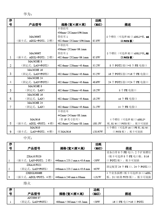
480mm×305mm×43.5mm <50W
描述
16 口 FE 电口+16 口 POTS
AN5006-09
2
(固定式,LAN+POTS)
450mm×300mm×45mm
AN5006-10
3
(固定式,LAN)
440mm×190mm×43.5mm
AN5006-15
(插卡式,ADSL+POTS,4 槽)
8 个 POTS 接口+8 个 FE 电接口
MA5620E-16
3
(固定式,LAN+POTS)
482.6mm×220mm×43.6mm 35.2W
16 个 POTS 接口+16 个 FE 电接口
MA5620E-24
4
(固定式,LAN+POTS)
482.6mm×220mm×43.6mm 40.6W
24 个 POTS 接口+24 个 FE 电接口
ZXDSL9806H 3 (插卡式,ADSL+POTS,4 槽) 440mm x 240 mm x 88mm
<131W
4 个业务插槽(板卡可选择 24 口 ADSL 板、24/48 路 POTS 板),板卡可混插
烽火
序
号
产品型号
规格(宽×深×高)
功耗 (MAX)
AN5006-07
1
(固定式,LAN+POTS)
436mm×232mm×86.1mm
MA5606T
带挂耳 1
1 (插卡式,ADSL+POTS,2 槽) 482.6mm×232mm×86.1mm 85.8W
2 个槽位(可选择 32 口 ADSL2+板,32 口 POTS 板)
WNM6001 单向 N 渠道 60V 0.5A 电源 MOSFET 数据手册说明书

WNM6001Single N-Channel, 60V, 0.50A, Power MOSFETDescriptionsThe WNM6001 is N-Channel enhancement MOS Field Effect Transistor. Uses advanced trench technology and design to provide excellent R DS (ON) with low gate charge. This device is suitable for use in DC-DC conversion, power switch and charging circuit. Standard Product WNM6001 is Pb-free and Halogen-free.Features● Trench Technology● Supper high density cell design● Excellent ON resistance for higher DC current ● Extremely Low Threshold Voltage ● Small package SOT-23Applications● Driver for Relay, Solenoid, Motor, LED etc. ● DC-DC converter circuit ● Power Switch ● Load Switch ● ChargingHttp//:SOT-23Pin configuration (Top view)W61*W61= Device Code*= Month (A~Z) MarkingOrder information3 12Absolute Maximum ratingsThermal resistance ratingsa Surface mounted on FR-4 Board using 1 square inch pad size, 1oz copperb Surface mounted on FR-4 board using minimum pad size, 1oz copperc Pulse width<380µsd Maximum junction temperature T J=150°C.Electronics Characteristics (Ta=25o C, unless otherwise noted)On-Resistance vs. Drain currentOn-Resistance vs. Junction temperatureOn-Resistance vs. Gate-to-Source voltageThreshold voltage vs. TemperatureI D -Drain Current(A)N o r m a l i z e d G a t e T h r e s h o l d V o l t a g eTemperature (oC)V GS -Gate-to-Source Voltage(V)R D S (o n )-O n -R e s i s t a n c eN o m a l i z e dTemperature(oC)CapacitanceSingle pulse powerBody diode forward voltageGate Charge CharacteristicsV G S -G A T E -t o -s o u r c e V o l t a g e (V )Q g (nC)C (p F )Time(s)S DV SD -Source-to-Drain Voltage(V)Safe operating powerI D - D r a i n C u r r e n t (A )VDS- Drain Source Voltage (V)V DS (V)1E-41E-30.010.111010010001020304050P o w e r (W )Transient thermal response (Junction-to-Ambient)Square Wave Pulse Duration (s)N o r m a l i z e d E f f e c t i v e T r a n s i e n t T h e r m a l I m p e d a n c ePackage outline dimensionsSOT-23TOP VIEW SIDE VIEW SIDE VIEWSymbolDimensions in Millimeters Min.Typ.Max.A0.89 1.10 1.30 A10.00-0.10 b0.300.430.55 c0.05-0.20D 2.70 2.90 3.10E 1.15 1.33 1.50 E1 2.10 2.40 2.70 e0.95Typ.e1 1.70 1.90 2.10TAPE AND REEL INFORMATIONReel DimensionsQuadrant Assignments For PIN1Orientation In Tape1User Direction of FeedQ1Q2Q3Q4Q1Q2Q3Q47inch 13inch 2mm 8mm 4mm Q1Q2Q3Q48mm12mm。
NCS6001系列单串口通讯服务器

参数介绍:
产品型号
产品描述
串口数量
处理器
内存
速率
校验位
数据位
串口 停止位
流量控制
串口形式
保护
网口
网口形式 速率
A
B
C
D
单口 RS-
单口 RS-
单口 RS-
单口 RS-
232
232/422/485
232
232/422/485
1个
32bits 100MHz
2M
50-460800bps
None,Even,Odd,Space,Mark
5,6,7,8
1,1.5,2
RTC/CTS,XON/XOFF
DB9 针
15KV ESD 保护
RJ45
10/100M
10M
保护
软件 电源 环境 认证
协议
实 COM 驱动
操作温度 操作湿度 存储温度 存储湿度
尺寸图:
2KV 电磁隔离 DHCP、Telnet、TCP、UDP、
IP、ICMP、ARP、PPP Windows NT/2000/XP/2003 实 COM 驱动
GND
6
DSR
7
RTS
8
CTS
RXD + TXD―
RXD + TXD―
9
以上产品均含一个串口服务器、一个输入为 220VAC 输出为 5VDC 2A 的电源适配器、软件 安装光盘。
DB9 针管脚定义:
PIN
RS-232
RS-485 HALF RS-485 FULL
422
Байду номын сангаас
1
DCD
达塔数据盘型PS6600WC商品说明书

Structure
IP66F, IP67F, UL 50/50E,Type 1, Type 4X (indoor use only),Type 12,Type 13 NOTE:On the front panel when properly installed in an enclosure.
Weight
Voltage Drop
5 ms or less
20 ms or less
5 ms or less
20 ms or less
Power Consumption*4
Panel Unit Only: 73 W When power is not supplied to external devices (Max 138 W) Box Unit Only: 56 W When power is not supplied to external devices (Max 121 W)
Projected capacitive (multi-touch)
261.12 x 163.2 mm (10.28 x 6.43 in)
White LED (not user replaceable. Please contact customer support.)
50,000 hours or more (continuous operation at 25 °C [77 °F] before backlight brightness decreases to 25%)
260-pin SODIMM socket x 2, DDR4-2133 (Up to 16 GB/socket, up to 32 GB for 2 sockets)
Intel® UHD Graphics 620 (built in CPU)
卡美欧 COMIO C6联通版终端参数信息

卡美欧 COMIO C6联通版终端参数信息
标准配置:单电单充、数据线
颜色:火山灰、香槟金
尺寸/体积:145×73.5×10mm
重量:138g
屏幕参数:5.0寸、854×480(FWVGA)、26万色、电容触摸屏
网络频率:卡1:GSM 900/1800MHz、UMTS 900/2100MHz、TD-LTE 2555-2575MHz、LTE FDD 2100/1800MHz(B1/B3)
卡2:GSM 900/1800MHz
HSPA上下行峰值:5.76/21Mbps
4GLTE上下行峰值:50/150Mbps
基带芯片型号、架构及主频:展讯SC9830、Cortex-A7、四核1.5GHz
AP芯片型号、架构及主频:芯片同上
操作系统:Android 4.4.4
SIM卡类型:双卡均为3FF卡
摄像头:200万像素FF
副摄像头:无
重力感应:支持
NFC:不支持
WIFI/WAPI:支持
GPS:支持
FM:支持
蓝牙:支持,BT4.0
RAM:512MB
ROM:4GB
用户可用内置存储:3400MB
扩展存储卡:最大可支持至32GB
语音解决方案:CSFB
电池容量:1850mAh;(TD-LTE待机200小时;LTE FDD待机200小时;3G待机210小时、通话3小时;2G待机220小时、通话4小时)。
Moxa AWK-1131A 产品说明书

AWK-1131A SeriesEntry-level industrial IEEE802.11a/b/g/n wireless AP/clientFeatures and Benefits•IEEE802.11a/b/g/n AP/client support•Millisecond-level Client-based Turbo Roaming1•Integrated antenna and power isolation•5GHz DFS channel supportCertificationsIntroductionThe AWK-1131A industrial wireless AP/client meets the growing need for faster data transmission speeds by supporting IEEE802.11n technology with a net data rate of up to300Mbps.The AWK-1131A is compliant with industrial standards and approvals covering operating temperature, power input voltage,surge,ESD,and vibration.The two redundant DC power inputs increase the reliability of the power supply.The AWK-1131A can operate on either the2.4or5GHz bands and is backwards-compatible with existing802.11a/b/g deployments to future-proof your wireless investments.The Wireless add-on for the MXview network management utility visualizes the AWK's invisible wireless connections to ensure wall-to-wall Wi-Fi connectivity.Improved Higher Data Rate and Channel Capacity•High-speed wireless connectivity with up to300Mbps data rate•MIMO technology to improve the capability of transmitting and receiving multiple data streams•Increased channel width with channel bonding technology•Supports flexible channel selection to build up wireless communication system with DFSSpecifications for Industrial-grade Applications•Redundant DC power inputs•Integrated isolation design with enhanced protection against environmental interference•Compact aluminum housing,IP30-ratedWireless Network Management With MXview Wireless•Dynamic topology view shows the status of wireless links and connection changes at a glance•Visual,interactive roaming playback function to review the roaming history of clients•Detailed device information and performance indicator charts for individual AP and client devicesSpecificationsWLAN InterfaceWLAN Standards802.11a/b/g/n802.11i Wireless SecurityModulation Type DSSSOFDMMIMO-OFDMFrequency Band for US(20MHz operating channels) 2.412to2.462GHz(11channels)5.180to5.240GHz(4channels)1.The Turbo Roaming recovery time indicated herein is an average of test results documented,in optimized conditions,across APs configured with interference-free20-MHz RF channels,WPA2-PSK security,and default Turbo Roaming parameters.The clients are configured with3-channel roaming at100Kbps traffic load.Other conditions may also impact roaming performance.For more information about Turbo Roaming parameter settings,refer to the product manual.5.260to5.320GHz(4channels)25.500to5.700GHz(11channels)25.745to5.825GHz(5channels)Frequency Band for EU(20MHz operating channels) 2.412to2.472GHz(13channels)5.180to5.240GHz(4channels)5.260to5.320GHz(4channels)25.500to5.700GHz(11channels)2Frequency Band for JP(20MHz operating channels) 2.412to2.484GHz(14channels)5.180to5.240GHz(4channels)5.260to5.320GHz(4channels)25.500to5.700GHz(11channels)2Wireless Security WEP encryption(64-bit and128-bit)WPA/WPA2-Enterprise(IEEE802.1X/RADIUS,TKIP,AES)WPA/WPA2-PersonalTransmission Rate802.11b:1to11Mbps802.11a/g:6to54Mbps802.11n:6.5to300MbpsTransmitter Power for802.11a23±1.5dBm@6to24Mbps21±1.5dBm@36Mbps20±1.5dBm@48Mbps18±1.5dBm@54MbpsTransmitter Power for802.11n(5GHz)23±1.5dBm@MCS0/820MHz18±1.5dBm@MCS7/1520MHz23±1.5dBm@MCS0/840MHz17±1.5dBm@MCS7/1540MHzTransmitter Power for802.11b26±1.5dBm@1Mbps26±1.5dBm@2Mbps26±1.5dBm@5.5Mbps25±1.5dBm@11MbpsTransmitter Power for802.11g23±1.5dBm@6to24Mbps21±1.5dBm@36Mbps19±1.5dBm@48Mbps18±1.5dBm@54MbpsTransmitter Power for802.11n(2.4GHz)23±1.5dBm@MCS0/820MHz18±1.5dBm@MCS7/1520MHz23±1.5dBm@MCS0/840MHz17±1.5dBm@MCS7/1540MHzTransmitter Power2.4GHz26dBm18dBm18dBm5GHz(UNII-1)23dBm21dBm21dBm5GHz(UNII-2)23dBm21dBm21dBm5GHz(UNII-2e)23dBm23dBm23dBm5GHz(UNII-3)23dBm––Note:Based on regional regulations,the maximum transmission power allowed onthe UNII bands is restricted in the firmware,as indicated above.Receiver Sensitivity for802.11a(measured at5.680 GHz)Typ.-90@6Mbps Typ.-88@9Mbps Typ.-88@12Mbps Typ.-85@18Mbps Typ.-81@24Mbps Typ.-78@36Mbps2.DFS(Dynamic Frequency Selection)channel support:In AP mode,when a radar signal is detected,the device will automatically switch to another channel.However,according to regulations,after switching channels,a60-second availability check period is required before starting the service.Typ.-74@48MbpsTyp.-72@54MbpsNote:Due to a limitation in the receiver sensitivity performance for channels153and 161,it is recommended to avoid using these channels in your critical applications.Receiver Sensitivity for802.11n(5GHz;measured at 5.680GHz)Typ.-69dBm@MCS720MHzTyp.-71dBm@MCS1520MHzTyp.-63dBm@MCS740MHzTyp.-68dBm@MCS1540MHzNote:Due to a limitation in the receiver sensitivity performance for channels153and 161,it is recommended to avoid using these channels in your critical applications.Receiver Sensitivity for802.11b(measured at2.437 GHz)Typ.-93dBm@1Mbps Typ.-93dBm@2Mbps Typ.-93dBm@5.5Mbps Typ.-88dBm@11MbpsReceiver Sensitivity for802.11g(measured at2.437 GHz)Typ.-88dBm@6Mbps Typ.-86dBm@9Mbps Typ.-85dBm@12Mbps Typ.-85dBm@18Mbps Typ.-85dBm@24Mbps Typ.-82dBm@36Mbps Typ.-78dBm@48Mbps Typ.-74dBm@54MbpsReceiver Sensitivity for802.11n(2.4GHz;measured at2.437GHz)Typ.-70dBm@MCS720MHz Typ.-69dBm@MCS1520MHz Typ.-67dBm@MCS740MHz Typ.-67dBm@MCS1540MHzWLAN Operation Mode Access point,Client,SnifferAntenna External,2/2dBi,Omni-directionalAntenna Connectors2RP-SMA femaleEthernet InterfaceStandards IEEE802.3for10BaseTIEEE802.3u for100BaseT(X)IEEE802.3ab for1000BaseT(X)IEEE802.1X for authentication10/100/1000BaseT(X)Ports(RJ45connector)1Ethernet Software FeaturesManagement DHCP Server/Client,DNS,HTTP,IPv4,LLDP,Proxy ARP,SMTP,SNMPv1/v2c/v3,Syslog,TCP/IP,Telnet,UDP,VLAN,Wireless Search Utility,MXview,MXview Wireless,MXconfigSecurity HTTPS/SSL,RADIUS,SSHTime Management SNTP ClientFirewallFilter ICMP,MAC address,IP protocol,Port-basedSerial InterfaceConsole Port RS-232,8-pin RJ45LED InterfaceLED Indicators PWR,FAULT,STATE,SIGNAL,WLAN,LANInput/Output InterfaceButtons Reset buttonPhysical CharacteristicsHousing MetalIP Rating IP30Dimensions58x115x70mm(2.29x4.53x2.76in)Weight307g(0.68lb)Installation DIN-rail mounting,Wall mounting(with optional kit)Power ParametersInput Current0.56A@12VDC,0.14A@48VDCInput Voltage12to48VDCPower Connector1removable4-contact terminal block(s)Power Consumption 6.96W(max.)Reverse Polarity Protection SupportedEnvironmental LimitsOperating Temperature Standard Models:0to60°C(32to140°F)Wide Temp.Models:-40to75°C(-40to167°F)Storage Temperature(package included)-40to85°C(-40to185°F)Ambient Relative Humidity5to95%(non-condensing)Standards and CertificationsEMC EN55032/24EMI CISPR32,FCC Part15B Class AEMS IEC61000-4-2ESD:Contact:4kV;Air:8kVIEC61000-4-3RS:80MHz to1GHz:10V/mIEC61000-4-4EFT:Power:2kV;Signal:1kVIEC61000-4-5Surge:Power:2kV;Signal:1kVIEC61000-4-6CS:3VIEC61000-4-8PFMFRadio EN300328,EN301489-1/17,EN301893,FCC ID SLE-WAPN008,MIC,NCC,RCM,SRRC,WPC,KC,RCM,ANATELSafety EN60950-1,UL60950-1Vibration IEC60068-2-6MTBFTime749,476hrsStandards Telcordia SR332WarrantyWarranty Period5yearsDetails See /warrantyPackage ContentsDevice1x AWK-1131Series wireless AP/clientInstallation Kit1x cap,plastic,for RJ45port1x DIN-rail kitAntenna2x2.4/5GHz antennaDocumentation1x quick installation guide1x warranty cardDimensionsOrdering InformationModel Name Band Standards Operating Temp. AWK-1131A-EU EU802.11a/b/g/n0to60°C AWK-1131A-EU-T EU802.11a/b/g/n-40to75°C AWK-1131A-JP JP802.11a/b/g/n0to60°C AWK-1131A-JP-T JP802.11a/b/g/n-40to75°C AWK-1131A-US US802.11a/b/g/n0to60°C AWK-1131A-US-T US802.11a/b/g/n-40to75°C Accessories(sold separately)AntennasANT-WDB-ONF-07097dBi at2.4GHz or9dBi at5GHz,N-type(female),dual-band,omnidirectional antennaANT-WDB-ANM-03063dBi at2.4GHz or6dBI at5GHz,N-type(male),omnidirectional antennaANT-WDB-ONM-070707dBi at2.4GHz and07dBi at5GHz,N-type(male),dual-band omnidirectional antennaANT-WDB-ANM-05025dBi at2.4GHz or2dBI at5GHz,N-type(male),omnidirectional antennaANT-WDB-ARM-022dBi at2.4GHz or2dBi at5GHz,RP-SMA(male)omnidirectional rubber-duck antennaANT-WDB-ARM-02022dBi at2.4GHz or2dBi at5GHz,RP-SMA(male),dual-band,omnidirectional antennaANT-WDB-PNF-101110dBi at2.4GHz and11dBi at5GHz,N-type(female),dual-band directional antennaMAT-WDB-CA-RM-2-0205 2.4/5GHz,ceiling antenna,2/5dBi,MIMO2x2,RP-SMA-type(male)MAT-WDB-DA-RM-2-0203-1m 2.4/5GHz,desktop antenna,2/3dBi,MIMO2x2,RP-SMA-type(male),1m cableMAT-WDB-PA-NF-2-0708 2.4/5GHz,panel antenna,7/8dBi,MIMO2x2,N-type(female)ANT-WSB5-PNF-1616dBi at5GHz,N-type(female),single-band directional antennaANT-WSB-PNF-12-0212dBi at2.4GHz,N-type(female),single-band directional antennaANT-WSB-AHRM-05-1.5m5dBi at2.4GHz,RP-SMA(male),omnidirectional/dipole antenna,1.5m cableWireless Antenna CablesA-CRF-RFRM-J1-60RP-SMA(male)to RP-SMA(female)with JSF-141cable,0.6mA-CRF-RFRM-R4-150RF magnetic base,RP-SMA(male)to RP-SMA(female)RG-174/U cable,1.5mA-CRF-RMNM-L1-300N-type(male)to RP SMA(male)LMR-195Lite cable,3mA-CRF-RMNM-L1-600N-type(male)to RP SMA(male)LMR-195Lite cable,6mA-CRF-RMNM-L1-900N-type(male)to RP SMA(male)LMR-195Lite cable,9mSurge ArrestorsA-SA-NFNF-020to6GHz,N-type(female)to N-type(female)surge arresterA-SA-NMNF-020to6GHz,N-type(male)to N-type(female)surge arresterWireless AdaptersA-ADP-RJ458P-DB9F-ABC01DB9female to RJ45connector for the ABC-01SeriesWireless Terminating ResistorsA-TRM-50-RM50-ohm terminating resistor with RP-SMA male connectorWall-Mounting KitsWK-51-01Wall mounting kit with2plates(51.6x67x2mm)and6screws©Moxa Inc.All rights reserved.Updated Aug17,2022.This document and any portion thereof may not be reproduced or used in any manner whatsoever without the express written permission of Moxa Inc.Product specifications subject to change without notice.Visit our website for the most up-to-date product information.。
世纪网通 中继网关 x6-2.1技术规格及功能说明

X6-2.1系统说明一、概述X6-2.1是一款小容量V oIP交换机。
它主要用于把基于IP技术的新一代语音业务网连接到传统的中继线设备上,如公共电话交换网(PSTN)的端局或汇接局,或者企业的小交换机(PBX)。
作为电信级的V oIP 网关设备,X6 是针对电信运营商、增值业务供应商以及大中型企业对V oIP 的要求而设计的。
与其他类似产品相比,在性能、系统可靠性、兼容性以及价格等方面的优势十分明显。
高效的软硬件设计和强大的处理能力,保证了X6在满负载流量状况下仍能实现PCM 语音信号与IP 分组包的转换,完成语音信号的编解码,以及回声消除等主要功能。
X6支持ISDN PRI信令(DSS1)、七号信令(SS7)、R2以及V5.2等多种信令,并同国内外市场上众多的软交换完成了互连互通测试(Interoperability Test)。
X6采用模块化结构,实时嵌入式操作系统,无阻塞交换,功耗低,可靠性高,是低成本高效率VOIP的最佳方案。
二、功能特性X6-2.1 IPPBX具有过载控制、黑白名单等多种功能特性。
主要功能特性如下表所示X6-2.1主要功能特性说明功能特性说明呼叫控制和处理具有本地电话和长途电话交换设备的功能,支持两方和多方呼叫的建立,可以控制媒体网关传送各种信号音。
黑白名单预制了两个限呼组:黑名单、白名单,两个限呼组之间存在固定的限呼关系,X6-2.1 IPPBX工具这个限呼关系来决定是允许或者拒绝一次呼叫。
支持的信令和协议支持SS7、PRI、Q.SIG信令,支持SIP协议。
业务功能可以提供PSTN/ISDN业务,包括基本业务和补充业务。
实现与SIP终端以及相邻的IPPBX互通智能路由在IP或TDM中继故障后自动重选,另外能够根据实际需求配置中继选路的策略以达到局间通信的可靠性和费用最低的要求。
虚拟IP-PBX 通过虚拟IP-PBX特性,同一台X6-2.1 IPPBX可以为多个小公司提供服务。
深安集团关于中国联通3G类运营商产品资料

功能特点录像功能外接无线防盗报警功能1,USB接孔,USB或无线手槟个性菜单设置。
130万像素摄象机,远程3G手机视频电话监控2,云台全方位左右360度上下90度旋转,夜间有8米红外夜视效果,内置U=3.7伏特锂电4,远程喊话,远程对讲功能5,无防盗报警功能,市电停电后云台无法转动但不影响视频通话,有SD卡本地存储功能两种情况下录像:1、远程主动指令录像开始和关闭,录在SD卡内,录到60分钟后,后面视频自动覆盖前面视频2、本地报警接通视频电话之前,自动录像。
无线防盗报警功能可接30个以上的无线配件(烟感,气感,水感,玻璃破碎探测器,遥控器等),不需要破坏原装修。
√√√√√√√√√√√√√√√√√√√√√√√√√√√可视摄像头功能,可控制摄像头左右360度,上下90度旋转,8米清晰红外夜视,USB接口设置,内置3.7V锂电可视摄像头功能,可控制摄像头左右360度,上下90度旋转,8米清晰红外夜视,USB接口设置,内置3.7V锂电可视摄像头功能,可控制摄像头左右360度,上下90度旋转,8米清晰红外夜视,USB接口设置,内置3.7V锂电可视摄像头功能,可控制摄像头左右360度,上下90度旋转,8米清晰红外夜视,USB接口设置,内置12V锂电可视摄像头功能,可控制摄像头左右360度,上下90度旋转,8米清晰红外夜视,USB接口设置,内置12V锂电SA-N-B83-W++√√√√√√√√√√所有设备都有的基本功能SA-N-B80-W SA-N-B80-W+SA-N-B80-W++√SA-N-B80-W++远程手机视频电话监控,130万像素全方位上下左右360度旋转摄像头,带视频通话喇叭接口,接上喇叭即可双向通话。
红外夜视监控图象质量好,内置U=3.7伏特锂电,可依需要提供TF/SD卡功能(可选,加30元),无防盗报警功能,市电停电后云台无法转动但不影响视频通话,配置:3G摄像机1台+电源1只增加电子变焦和亮度可调功能,增加全程语音提示操作SA-N-B81-W+远程手机视频电话监控,130万像素全方位上下左右360度旋转摄像头,带视频通话喇叭接口,接上喇叭即可双向通话。
EL31116CN EL31216CN EL31316CN EL31416CN 用户手册说明书

用户手册EL31116CN/EL31216CN/ EL31316CN/EL31416CN 数字无绳电话机无绳电话机欢迎欢迎购买 AT&T 产品。
在使用此 AT&T 产品前,请仔细阅读用户手册中第 53 至 54 页的重要安全信息。
为了更容易地安装和使用您的电话,也请仔细阅读用户手册中所有操作说明和常见问题的帮助信息。
您也可以浏览我们的网站或致电服务热线。
网站:服务热线:400-022-9929请保管好销货收据,以便在享受质保服务时作为相关证明。
产品名称: 数字无绳电话机中国专用型号:HWDCD2310(3)P/TSD企业型号: EL31116CN/EL31216CN/EL31316CN/EL31416CN© 2017-2018 伟易达通讯设备有限公司保留所有权利。
此使用手冊上所载述的 AT&T 商标及 AT&T 图标为 AT&T 拥有的商号,并在 AT&T 的品牌许可协议下授权予香港伟易达通讯设备有限公司使用。
中国印刷。
部件清单请保管好销货收据, 以便在享受质保服务时作为相关证明。
EL31116CN/EL31216CN/EL31316CN/EL31416CN 的包装盒中包括以下物品:无绳子机充电器(EL31116不含充电器)电话线主机电源适配器AAA 镍氢可充电电池无绳子机用户手册座机保修卡电池盖用戶手冊EL31116CN/EL31216CN/ EL31316CN/EL31416CN 2.4GHz 数字无绳电话机目录安装 (1)快速使用指南.-.子机 (2)快速使用指南.-.座机 (5)座机和充电座安装 (6)安装座机 (6)安装充电座 (6)安装电池和充电 (7)电话设置 (9)无绳子机设置 (10)设置日期 / 时间 (10)铃声音量 (12)内线通话的响铃音调 (12)外线通话的铃声音调 (13)闹钟设置 (13)重命名子机 (15)按键音 (16)电池提示音 (16)待机状态下的屏幕显示 (17)自动应答 (18)重设子机 (18)座机设置(使用无绳子机) (19)铃声音量 (19)铃声音调 (19)拨号模式 (20)闪断时间 (20)IP 号码 (21)更改 PIN 码 (22)电话操作 (23)拨打电话 (23)挂机拨号(预拨号) (23)接听来电 (23)结束通话 (23)免提通话 (24)安静模式 (24)重拨上次的号码 (25)通话时的操作 (26)音量控制 (26)静音 (26)内线通话 (27)拨打内线电话 (27)转移外线通话 (28)进行三方通话 (29)电话簿 (30)容量 (30)新增电话簿记录 (30)拨号键 (31)查看电话簿记录 (32)按姓名搜索 (33)搜索电话簿 (33)拨打、编辑或删除电话.簿记录 (34)显示拨号 (34)删除一个电话簿记录 (34)编辑电话簿记录 (35)删除所有电话簿记录 (36)查看电话簿使用情况 (36)来电显示 (37)来电显示操作 (38)查看来电清单 (38)查看来电清单记录的详细信息 (38)拨打来电清单的记录 (39)删除一个来电清单记录 (39)删除所有来电清单记录 (39)储存来电显示清单号码至电话簿 (40)来电信息缺失的原因 (41)增加及登记新子机 (42)登记子机到座机 (42)解除子机登记 (43)解除子机登记 (43)屏幕图标和提示音 (44)子机屏幕图标 (44)子机提示音 (45)常见问题 (46)维护 (52)重要安全信息 (53)安全信息 (53)特别注意 (54)产品中有毒有害物质或.元素的名称及含量表 (55)产品技术参数 (57)2.4GHz FHSS军用跳频扩频数字无绳通讯技术 (57)电话操作范围 (57)安装在电话线墙壁插口和非开关控制的电源插座附近安装您的座机。
牙克石人民广播电台采购设备参数
牙克石人民广播电台采购设备参数1. 背景随着牙克石地区的经济发展和社会进步,人民生活的各个方面都得到了极大的改善和提高。
而人民广播电台作为地区媒体的重要组成部分,在宣传和传播文化、促进社会信息的传递、维护社会稳定等方面发挥着举足轻重的作用。
为更好地履行自身职责,人民广播电台决定进行设备更新和升级,以适应信息技术的快速发展和广播媒体日益复杂的传输需求。
本文将详细介绍采购设备的参数要求,以供参考。
2. 采购设备参数2.1 收音机收音机作为广播电台的主要播放设备,质量的好坏直接影响到听众的收听效果。
因此,在采购收音机时需要考虑以下几个方面:•频段范围:收音机需要支持广播电台所使用的频段范围。
对于人民广播电台而言,需要支持FM和AM两种频段。
•接收信号质量:收音机的接收信号质量需要尽可能好,能够抵抗干扰和衰减,以保证听众能够收听到清晰的声音。
•功放效果:收音机需要具有较好的功放效果,能够产生适宜的音量和音效,以满足各种场合的需求。
•外接接口:收音机需要具备外接接口,能够与电脑等其他设备相连接,以方便录制和制作广播节目等操作。
2.2 话筒话筒是广播电台录制和制作节目的重要设备,其功效的优劣直接关系到广播节目的质量。
因此,在采购话筒时需要考虑以下几个方面:•灵敏度:话筒的灵敏度需要足够高,能够识别和捕捉声音的细微变化。
•噪音抑制:话筒的噪音抑制功能需要足够好,能够有效消除外界噪音的干扰。
•防震功能:话筒需要具有一定的防震功能,能够降低由外界震动造成的噪音干扰。
•类型选择:针对不同的讲话环境和应用场合,需要选择不同类型的话筒,例如无线麦克风、手持麦克风、麦克风阵列等等。
2.3 混音器混音器是广播电台录制和制作节目时的重要设备,它能够将多个输入信号进行混合、调整音量和音效,并输出到后级设备进行处理和播放。
因此,在采购混音器时需要考虑以下几个方面:•轨道数:混音器的轨道数需要与实际需要录制的节目和信号数量匹配,过多或过少都会影响使用效果。
P6001输出接口说明
P6001输出接口说明
首先,P6001输出接口拿到手要先了解它的按键,基本的按键包括,开关机键,暂停开始键,声音键、前进键、倒退键、FM\AM切换键和数字键,还有包括屏幕、天线等外置的一些部件,我们要熟悉这些按键。
P6001输出接口具体使用方法如下:
1、按键的具体功能,开关机键的方向,TUNING是调谐钮,就是你找台的旋钮,MW是中波,SW是短波,FM是调频,MW、SW、FM应该是一个多位开关或是电子开关切换的。
2、然后按下MW,P6001输出接口收中波,中波传送距离较远,比如中央广播电台、临省的广播电台都可收到,但音质不太好。
FM是调频广播,它的距离较近,但音质好,可传送立体声信号,比如你所在城市的都市调频、交通台、音乐台等等。
3、把P6001输出接口打到SW,拉出天线,最好接一个室外天线,可收听到短波,短波最远,可收听到国外电台。
除此之外,在使用时应当注意收听完毕,应及时关闭电源开关,如果在使用过程中觉得音质差或者音量突然变小,可能有一部分因素是因为耳机电池电量不足所导致的,应当及时更换电池;在电池选用方面建议使用“南孚”等高性能碱性电池; 除此之外,如果P6001输出接口长期不使用,
应当及时将电池取出,以免电池变成酸性流水从而损坏耳机。
