SoPC实例
SOPC技术在汽车电子领域的应用
全 部 内容 , 除 了 以 处 理 断发展, 现代汽车 逐步 电子化 、 多媒体 化和智能化, 电子技术 的应用越来越广泛 [] 专家预测汽车上装用的 电子 1。 装置成本将逐 年提 高, 汽车将 由单纯的机械产 品向高级 的机 电一体化产 品 方 向发展, 成为所谓 的“ 电子汽车 ” 传统 M U A I 。 C 、S C己很难满足汽车电子设 计 灵 活 性 、 定性 、 成 本 、 速 开 发 等 要 求 , S P 稳 低 快 而 O C技 术 能 提供 更 高 的 性 能和更多 的功能 , 成本 更低 、 风险更小 、 灵活性更高 , 而且在设计后 期更易 变更 , 甚至可对 己经投入应用的产品进行升级 , 因此基 于 S P OC技术 将成 为 未来汽车电子设计 的理想解决方案 。 1 Sp 、0 c简介 S s e O a P o r m a ] C i , 编 程 片 上 系 统 [] 它 是 用 ytm n rgambe hp 可 2, 可编程逻辑技术把整个系统放到一块硅片上, 来用于嵌入式 系统 的研 究和 电子 信 息 处理 。它 是 一 种 特 殊 的 嵌 入 式 系 统 , 是 片上 系 统 (O ) 即 由 单 它 SC , 个芯 片完成 整个 系统的主要逻 辑功能 , 但它不 是简单 的 S C 是可编程 系 O, 统 , 有 灵 活 的 设计 方 式 , 裁 减 、 扩 充 、 升 级 , 具 备 软 硬 件 在 系统 可 具 可 可 可 并
特点 。
S P 特 点 包 括 : 少 包 含 一 个 嵌 入 式 处 理 器 内核 ; 有 小 容 量 片 内 O C的 至 具 高 速 RM资源 :丰 富 的 I Cr A P o e资 源 可 供 选 择 ;足 够 的片 上 可 编 程 逻 辑 资 源 : 理器调试接 【和 FG 处 _ _ PA编 程 接 口 : 能 包 含 部 分 可 编 程 模 拟 电路 ; I 可 单 芯片、 功耗、 低 微封 装 。
SOPC流水灯实验

第1章SOPC流水灯实验实验步骤如下:1.1 实验目的熟悉使用QuartusII软件;熟悉使用SOPC Builder建立自己的Nios2系统;熟悉使用Nios II IDE软件进行编程、调试和下载程序。
1.2 实验设备硬件:PC机一台MagicSOPC教学实验开发平台一套软件:Quartus II7.0、Nios II IDE 7.01.3 实验内容本实验的内容是使用QuartusII中的SOPC Builder建立一个NiosII系统,并使用NiosII IDE编写C程序,在NiosII IDE中下载程序、调试程序。
1.4 实验预习要求预习《SOPC嵌入式系统实验教程二》第3章3.3节,熟悉建立带DDR SDRAM的NiosII 系统;熟悉PIO外设的使用。
1.5 实验步骤1.5.1使用Quartus II建立工程仿照Quartus II7.0软件使用的实验,建立一个Nios2_system的工程,并使工程名与实体名相同。
1.5.2建立Nios II 系统硬件(1)在Quartus II主界面中选择File→New打开新建文件对话框,如图1.1所示,在对话框中选择Block Diagram/Schematic File,单击OK建立一个空的顶层原理图设计文件。
图1.1 新建文件对话框(2)在Quartus II主界面中选择Tools→SOPC Builder打开如图1.2所示的对话框,在System Name一栏中填入Nios II 系统的名称nios2_ep2c35,然后单击OK进入到如图1.3所示的SOPC Builder的主界面。
图1.2 Create New System对话框图1.3 SOPC Builder的主界面(3)双击SOPC Builder主界面左侧中的“Nios II Processor-Altera Corporation”,出现Nios II CPU的配置向导对话框,如图1.4所示,在这果可以有三种Nios II CPU选择,我们选择快速型的Nios II/f,然后单击Next进入下一步配置。
《基于SoPC的盲人阅读器的设计与实现》范文
《基于SoPC的盲人阅读器的设计与实现》篇一一、引言随着科技的不断发展,盲人群体对于辅助阅读工具的需求日益增长。
为了满足这一需求,本文提出了一种基于SoPC(System on a Programmable Chip)的盲人阅读器设计与实现方案。
该方案旨在通过先进的SoPC技术,为盲人提供更加便捷、高效的阅读体验。
二、SoPC技术概述SoPC(System on a Programmable Chip)是一种可编程芯片系统,具有高度集成、低功耗、高性能等优点。
其核心技术在于将各种功能模块集成在单一芯片上,包括处理器、存储器、接口等,从而实现对复杂系统的集成与优化。
SoPC技术广泛应用于智能家居、工业控制、医疗设备等领域,具有很高的应用价值。
三、设计与实现1. 系统架构设计基于SoPC的盲人阅读器设计采用模块化架构,主要包括语音合成模块、文本识别模块、控制模块和电源管理模块等。
其中,语音合成模块负责将识别的文本转化为语音输出;文本识别模块负责读取并识别纸质或电子文档中的文字;控制模块负责协调各模块之间的通信与操作;电源管理模块负责为整个系统提供稳定的电源供应。
2. 硬件设计硬件设计是实现盲人阅读器的关键环节。
在硬件设计中,我们采用先进的SoPC技术,将各模块集成在单一芯片上。
其中,处理器选用高性能、低功耗的处理器芯片;存储器采用大容量、高速度的Flash存储器;接口包括USB、SD卡等,以便实现数据的传输与存储。
此外,为了满足盲人的使用需求,我们还特别设计了触摸屏和语音控制功能。
3. 软件设计软件设计是实现盲人阅读器的另一关键环节。
在软件设计中,我们采用嵌入式操作系统,以实现对各模块的协调与控制。
具体而言,我们开发了文本识别算法和语音合成算法,以实现对纸质或电子文档的识别与语音输出。
此外,我们还设计了用户界面和语音控制程序,以便用户能够方便地操作和使用该阅读器。
4. 实现过程在实现过程中,我们首先完成了硬件电路的搭建与调试,确保各模块能够正常工作。
Quartus II 8.0 SOPC实例讲解
在SOPC Builder主界面左侧组件列表中选中Interval Timer ,按鼠标右键,在弹出的菜单中选择Add New Interval Time,显示如图30所示的定时器配置界面。按照默认的设置。配置不作改变,即可生成一个初始周期为1ms的定时器,单击Finish按钮完成定时器的设置。
图1 sopc系统设计流程
2
用SOPC系统在DE2平台上实现一个计数器。先在DE2平台上建立SOPC系统的硬件,这个系统包括一个NIos II/s嵌入式处理器、存储器、一个JTAG UART及一个定时器,一个ID模块。另外,我们将加入一个自定义组件,实现对DE2平台上七段数码管的控制。
1.
启动Quartus II软件,用New>New Project Wizard…菜单在Quartus II中新建一个工程,本例中将工程的工作目录设定在G:\DE2,工程的名称为niosii,如图4所示,如果是希望使用自己已有的工程,则点击图4中所示的Using Existing Project Setting按钮,,但是在本例中不需要添加已有工程的配置。按下next后,器件中选择EP2C35F672C6,向导完成后的汇总界面如图8所示。
图24
图25
图26
图27
6.
在SOPC Builder主界面左侧的组件列表中,选择JTAG UART,按鼠标右键,在弹出的菜单中选择Add New JTAG UART,显示如图28所示的JTAG UART配置界面。按照默认设置,配置不作改变,单击Finish按钮完成JTAGUART的设置。
图28
图29
图13
图14
图15
4.
在SOPC Builder左侧的组件列表中,选择Nios II Processor,,按鼠标右键,在弹出的菜单中选择Add New Nios II Processor,显示如图17所示的Nios II处理器的配置界面。选择Nios II/s作为本设计的处理器,从界面上可以看到,Nios II/s占用约1200~1400个逻辑单元,2个M4K RAM块。由于可以添加指令缓存,缓存需要占用额外的M4K RAM块,因此Nios II/s比Nios II/e相比,增加了指令缓存、分支预测、硬件乘法器及硬件除法器。Nios II/s的最好性能可达25MIPS.
基于SoPC汽车安全监控系统设计

基于SoPC汽车安全监控系统设计基于SoPC的汽车平安监控系统采纳公司最新的SoPC(可编程片上系统)解决计划——Nios处理器软核为核心,协作和GSM系统,对汽车的停放和运行状态举行监控。
系统监测、记录和储存汽车在行驶过程中的各种数据,一旦浮现平安问题,立刻采纳GSM无线通信方式通知相关人员和单位,并随时发送通过GPS获得的汽车位置等数据,为问题的解决提供准时、精确和牢靠的信息,须要时通过GSM对汽车举行远程控制。
基于SoPC的汽车平安监控系统可广泛应用于汽车的防盗、日常维护和交通事故的处理,为车辆故障提供有效的测试手段。
1 系统硬件组成[/table]设计采纳Altera公司的SoPC开发工具。
系统的开发包括硬件和软件两大部分。
用法SoPC Builder生成Nios处理器,Nios嵌入式处理器开发工具允许用户配置一个或多个Nios CPU,从标准库中添加外围设备,综合处理自定义系统,与 II设计软件一起编译系统。
软件开发的步骤是:利用SoPC Builder生成的软件文件,用文本编辑器编写汇编语言或C/C++源程序,用GNUPro软件开发工具举行程序设计、连编和调试。
GNUPro将源程序连编(包括汇编/编译和衔接)成可执行程序,通过下载电缆对可执行程序举行调试和运行。
Quartus II设计软件提供全面有效的设计环境,将设计、综合、布局和验证以及第三方工具接口集成在一个无缝的环境中。
利用集成在Quartus II 3.0中的SoPCbuilder可以创建自己的Nios CPU系统。
Nios是Altera公司开发的16/32位嵌入式处理器软核。
Altera公司推出了新一代多种系列,本设计选用低成本的Cyclone系列器件EP1C12,其具有12 060个规律单元,52个M4K RAM块,239 616个RAM位和2个锁相环,最大用户I/O引脚249。
系统硬件组成框图由Nios系统和外部设备两部分组成,1所示。
《基于SOPC的目标跟踪系统设计》范文
《基于SOPC的目标跟踪系统设计》篇一一、引言随着科技的进步和计算机视觉技术的不断发展,目标跟踪系统在各个领域中的应用日益广泛,包括安防监控、自动驾驶、人机交互等。
而SOPC(System on a Programmable Chip,可编程芯片上的系统)技术以其高度的集成性、灵活性和可定制性,为目标跟踪系统的设计提供了新的可能。
本文将探讨基于SOPC的目标跟踪系统设计,分析其设计原理、方法及实现过程。
二、SOPC技术在目标跟踪系统中的应用SOPC技术是一种集成了处理器、存储器、外设及可编程逻辑的单芯片系统。
在目标跟踪系统中,SOPC技术可以提供强大的计算能力和灵活的硬件配置,以满足复杂的目标跟踪算法对计算资源和硬件接口的需求。
通过将目标跟踪算法与SOPC技术相结合,可以实现高效、实时的目标跟踪。
三、目标跟踪系统设计原理目标跟踪系统的设计主要包括硬件设计和软件设计两部分。
硬件设计主要涉及SOPC芯片的选型、电路设计、接口设计等;软件设计则包括目标跟踪算法的设计与实现、操作系统及驱动程序的开发等。
在硬件设计方面,需要根据目标跟踪系统的需求,选择合适的SOPC芯片,并设计相应的电路和接口,以保证系统的稳定性和可靠性。
在软件设计方面,需要针对目标跟踪算法进行优化和实现,以满足实时性的要求。
同时,还需要开发操作系统及驱动程序,以实现软硬件之间的良好交互。
四、目标跟踪系统设计方法基于SOPC的目标跟踪系统设计方法主要包括以下几个步骤:1. 需求分析:明确目标跟踪系统的应用场景、性能指标和功能需求。
2. 硬件选型与设计:根据需求选择合适的SOPC芯片,并设计相应的电路和接口。
3. 软件设计与实现:针对目标跟踪算法进行优化和实现,开发操作系统及驱动程序。
4. 系统集成与测试:将硬件和软件进行集成,进行系统测试和性能评估。
5. 优化与调试:根据测试结果进行优化和调试,提高系统的性能和稳定性。
五、实现过程及关键技术在实现基于SOPC的目标跟踪系统的过程中,需要掌握以下关键技术:1. SOPC芯片的选型与配置:根据系统需求选择合适的SOPC 芯片,并配置相应的硬件资源。
《基于SOPC的嵌入式系统架构及应用验证》范文

《基于SOPC的嵌入式系统架构及应用验证》篇一一、引言随着信息技术的迅猛发展,嵌入式系统已广泛应用于各类电子产品和系统中,发挥着日益重要的作用。
而系统级芯片(SOPC)的出现为嵌入式系统提供了新的解决方案。
SOPC将芯片上的各个功能模块集成在一个单一的芯片上,提高了系统的集成度和性能。
本文旨在探讨基于SOPC的嵌入式系统架构及其应用验证。
二、SOPC的嵌入式系统架构1. 硬件架构SOPC的嵌入式系统硬件架构主要包括处理器、存储器、接口和总线等部分。
其中,处理器是系统的核心,负责执行各种计算任务;存储器包括内存和外存,用于存储程序和数据;接口和总线用于连接各个硬件模块,实现数据的传输和交换。
2. 软件架构SOPC的嵌入式系统软件架构主要包括操作系统、中间件和应用软件等部分。
操作系统负责管理硬件资源,提供各种服务;中间件用于实现不同软件模块之间的通信和交互;应用软件则是根据具体应用需求开发的软件程序。
三、应用验证为了验证基于SOPC的嵌入式系统架构的有效性和可靠性,需要进行应用验证。
应用验证主要包括以下几个方面:1. 功能性验证功能性验证主要是验证系统的各项功能是否符合设计要求。
通过编写测试用例,对系统的各个功能进行测试,确保系统能够正常工作。
2. 性能验证性能验证主要是评估系统的性能指标,如处理速度、功耗等。
通过与同类产品进行对比,分析系统的性能优劣,为后续的优化提供依据。
3. 可靠性验证可靠性验证主要是通过模拟实际使用环境,对系统进行长时间的运行测试,以检验系统的稳定性和可靠性。
通过分析测试结果,找出潜在的问题和缺陷,为后续的改进提供依据。
四、应用领域及案例分析基于SOPC的嵌入式系统具有广泛的应用领域,如智能家居、工业控制、医疗设备等。
下面以智能家居为例,分析基于SOPC 的嵌入式系统的应用。
在智能家居系统中,SOPC的嵌入式系统负责控制各种智能设备的运行和通信。
通过与各种传感器和执行器相连,实现家居环境的智能监测和控制。
sopc 实验指导EP2C35

实验一Hello from Nios II一.实验目的1. 熟悉用Quartus II开发SOPC的基本流程。
2. 熟悉用SOPC Builder进行NiOS II CPU开发的基本流程。
3. 熟悉用NIOS II IDE进行C语言编译、下载的基本过程。
4. 掌握NIOS II 集成开发环境。
二.实验内容实验完成的是一个简单的系统设计,系统中包括NIOS CPU 、作为标准输入/输出的JTAG UART、存储器on chip memory和SDRAM、并行输入输出PIO。
通过SOPC 实现NIOS 系统配置、生成以及与NIOS II 系统相关的监控和软件调试平台的生成;在NIOS II IDE中完成系统软件开发和调试;通过Quartus II 完成NIOS 系统的分析综合、硬件优化、适配、配置文件编程下载以及硬件系统调试等。
实验最终实现在NIOS II IDE 窗口打印一条信息——―Hello from Nios II ‖。
三.实验平台硬件平台:SOPC 实验开发系统软件平台:Quartus II 7.0 NIOS II IDE四.实验原理Altera 公司提供的Nios II 嵌入式微处理器软核专为SOPC系统设计核优化,是一种面向用户、可以灵活定制的通用RISC嵌入式处理器。
它采用Avalon总线结构通信接口,带有增强的内存、调试和软件功能,可采用汇编或C、C++等进行程序优化开发。
Nios II具有32位指令集、32位数据通道和可配置的指令及数据缓冲。
与普通嵌入式CPU系统的特性不同,其外设可以灵活选择或增减,可以自定制用户逻辑为外设,可以允许用户定制自己的指令集。
由硬件模块构成的自定制指令可通过硬件算法操作来完成复杂的软件处理任务,也能访问存储器或Nios II 系统外的接口逻辑。
设计者可以使用Nios II及外部的Flash、ROM、SRAM等,在FPGA上构成一个嵌入式处理器系统。
基于NiOS II处理器软核的SOPC系统设计是一个软硬件协同开发的过程,在设计时可分为硬件核软件两部分,需要多款EDA软件和软件开发环境的相互协同配合。
《基于SOPC的目标跟踪系统设计》范文

《基于SOPC的目标跟踪系统设计》篇一一、引言随着科技的不断发展,目标跟踪系统在众多领域中发挥着越来越重要的作用,如安防监控、自动驾驶、智能机器人等。
SOPC (System on a Programmable Chip,可编程芯片上的系统)因其高性能、高集成度和灵活性等优势,成为目标跟踪系统设计的理想选择。
本文将介绍一种基于SOPC的目标跟踪系统设计方法,包括硬件架构设计、软件算法设计以及系统测试与性能评估等方面。
二、硬件架构设计1. 处理器选择SOPC的核心是处理器,其性能直接影响到整个系统的运行效率。
因此,在选择处理器时,应考虑其处理速度、功耗、集成度等因素。
通常,FPGA(Field Programmable Gate Array)因其可编程性和高并行处理能力,成为目标跟踪系统硬件架构设计的首选。
2. 传感器模块传感器模块是目标跟踪系统获取目标信息的重要途径。
根据实际需求,可选择摄像头、红外传感器、雷达等传感器。
其中,摄像头因其成本低、信息丰富等优点,在目标跟踪系统中得到广泛应用。
3. 数据传输与存储模块数据传输与存储模块负责将传感器采集的数据传输到处理器进行处理,并将处理结果存储或传输到其他设备。
该模块应具备高速、稳定的数据传输能力以及大容量、高可靠性的存储能力。
三、软件算法设计1. 目标检测算法目标检测是目标跟踪系统的关键技术之一。
常用的目标检测算法包括基于模板匹配的方法、基于背景减除的方法、基于深度学习的方法等。
在实际应用中,应根据具体场景和需求选择合适的算法。
2. 目标跟踪算法目标跟踪算法是实现目标持续追踪的核心。
常见的目标跟踪算法包括基于滤波的方法、基于相关性的方法、基于深度学习的方法等。
为了提高跟踪精度和实时性,通常采用多种算法相结合的方式。
3. 系统软件架构系统软件架构应具备模块化、可扩展、可维护等特点。
通常采用分层设计的思想,将系统分为硬件驱动层、算法层、应用层等层次结构。
SOPC课件SOPC技术

• 用户代码 • 库函数 • 操作系统(RTOS)
GNU Tools
硬件开发使用Quartus II和SOPC Builder
3.1 SOPC开发流程
软件开发
• 即使在没有软件开发的目 标板的情况下,也可以经过 编译、连接后通过Nios II指 令 仿 真 器 (ISS) 运 行 和 调 试 代码。
• Quartus II软件用来选取具 体的Altera FPGA器件型号, 然后为Nios II系统上的各I/O 口分配管脚。
处理器库 外设模块库
硬件开发
• HDL 源文件 • 测试台
SOPC Builder GUI
配置Nios II处理器 选择并配置外设.IP
连接各外设模块 分配外设地址和中断
生成系统
SDRAM 存储器
JTAG 调试模块
Nios II 处理器内核
SDRAM 控制器
Avalon
Flash 存储器
SRAM 存储器
片内ROM
总
线
三态桥
UART Timer1 Timer2 LCD显示驱动 通用I/O 以太网接口 CompactFlash 接口
用户自定义
TXD RXD
LCD Screen Buttons LED .etc Ethernet MAC/PHY Compact
SOPC课件SOPC技术
知识要点回顾
sopc
System On Programmable Chip,可编程的片上系统。 是Altera公司提出来的一种灵活、高效的SOC解决方案。
SOPC将处理器、存储器、I/O、LVDS、CDR等系统设 计需要的功能模块集成到一个可编程器件上,构成一个可 编程的片上系统。
《基于SOPC的目标跟踪系统设计》范文

《基于SOPC的目标跟踪系统设计》篇一一、引言随着科技的进步和智能化时代的到来,目标跟踪技术在军事侦察、安全监控、自动驾驶等领域有着广泛的应用。
系统性能的优化和硬件实现的可行性一直是研究的重点。
SOPC(System on a Programmable Chip)作为一种高度集成的可编程芯片系统,具有可定制性、灵活性和高性能等优点,使其成为目标跟踪系统设计的理想选择。
本文将详细探讨基于SOPC的目标跟踪系统设计,从设计需求、硬件架构、软件算法、系统实现及性能评估等方面进行全面分析。
二、设计需求目标跟踪系统的设计需求主要包括实时性、准确性、鲁棒性和可扩展性。
实时性要求系统能够快速响应并实时处理目标信息;准确性要求系统能够准确识别和跟踪目标;鲁棒性要求系统在复杂环境下仍能保持良好的性能;可扩展性则要求系统能够适应不同场景和需求的变化。
基于SOPC的目标跟踪系统设计应满足上述所有需求。
此外,考虑到系统实现的成本和硬件资源的限制,还需要考虑系统的功耗、体积和成本等因素。
三、硬件架构基于SOPC的目标跟踪系统硬件架构主要包括可编程逻辑器件、处理器、存储器等模块。
其中,可编程逻辑器件负责实现目标跟踪的硬件加速算法,处理器负责运行操作系统和上层应用软件,存储器则负责存储程序代码和数据。
通过合理的硬件架构设计,可以实现系统的实时性、准确性和鲁棒性要求。
四、软件算法软件算法是目标跟踪系统的核心部分,包括目标检测、特征提取、匹配跟踪等算法。
这些算法需要针对特定应用场景进行优化,以实现更好的性能。
在SOPC平台上,可以通过硬件加速的方式,提高算法的运行速度和准确性。
五、总结与展望基于SOPC的目标跟踪系统设计具有广泛的应用前景和重要的研究价值。
未来,随着技术的发展和需求的不断变化,我们需要继续研究更高效的算法和更优化的硬件架构,以实现更高性能的目标跟踪系统。
SOPC视频实验 附录

附录1:DE2‐70 通用管腿分配文件“pins‐de2‐70.tcl”#50MHz clock inputset_location_assignment PIN_AD15 -to iCLK_50set_location_assignment PIN_D16 -to iCLK_50_2set_location_assignment PIN_R28 -to iCLK_50_3set_location_assignment PIN_R3 -to iCLK_50_4#external SMA Clock inputset_location_assignment PIN_R29 -to iEXT_CLOCK#clock input for FPGA and TV Decoderset_location_assignment PIN_E16 -to iCLK_28#8 Green LEDset_location_assignment PIN_W27 -to oLEDG[0]set_location_assignment PIN_W25 -to oLEDG[1]set_location_assignment PIN_W23 -to oLEDG[2]set_location_assignment PIN_Y27 -to oLEDG[3]set_location_assignment PIN_Y24 -to oLEDG[4]set_location_assignment PIN_Y23 -to oLEDG[5]set_location_assignment PIN_AA27 -to oLEDG[6]set_location_assignment PIN_AA24 -to oLEDG[7]#18 Red LEDset_location_assignment PIN_AJ6 -to oLEDR[0]set_location_assignment PIN_AK5 -to oLEDR[1]set_location_assignment PIN_AJ5 -to oLEDR[2]set_location_assignment PIN_AJ4 -to oLEDR[3]set_location_assignment PIN_AK3 -to oLEDR[4]set_location_assignment PIN_AH4 -to oLEDR[5]set_location_assignment PIN_AJ3 -to oLEDR[6]set_location_assignment PIN_AJ2 -to oLEDR[7]set_location_assignment PIN_AH3 -to oLEDR[8]set_location_assignment PIN_AD14 -to oLEDR[9] set_location_assignment PIN_AC13 -to oLEDR[10] set_location_assignment PIN_AB13 -to oLEDR[11] set_location_assignment PIN_AC12 -to oLEDR[12] set_location_assignment PIN_AB12 -to oLEDR[13] set_location_assignment PIN_AC11 -to oLEDR[14] set_location_assignment PIN_AD9 -to oLEDR[15] set_location_assignment PIN_AD8 -to oLEDR[16] set_location_assignment PIN_AJ7 -to oLEDR[17]#VGAset_location_assignment PIN_D24 -to oVGA_CLOCKset_location_assignment PIN_B15 -to oVGA_SYNC_N set_location_assignment PIN_J19 -to oVGA_HSset_location_assignment PIN_H19 -to oVGA_VSset_location_assignment PIN_B16 -to oVGA_B[0]set_location_assignment PIN_C16 -to oVGA_B[1]set_location_assignment PIN_A17 -to oVGA_B[2]set_location_assignment PIN_B17 -to oVGA_B[3]set_location_assignment PIN_C18 -to oVGA_B[4]set_location_assignment PIN_B18 -to oVGA_B[5]set_location_assignment PIN_B19 -to oVGA_B[6]set_location_assignment PIN_A19 -to oVGA_B[7]set_location_assignment PIN_C19 -to oVGA_B[8]set_location_assignment PIN_D19 -to oVGA_B[9]set_location_assignment PIN_A10 -to oVGA_G[0]set_location_assignment PIN_B11 -to oVGA_G[1]set_location_assignment PIN_A11 -to oVGA_G[2]set_location_assignment PIN_C12 -to oVGA_G[3]set_location_assignment PIN_B12 -to oVGA_G[4]set_location_assignment PIN_A12 -to oVGA_G[5]set_location_assignment PIN_C13 -to oVGA_G[6]set_location_assignment PIN_B13 -to oVGA_G[7]set_location_assignment PIN_B14 -to oVGA_G[8]set_location_assignment PIN_A14 -to oVGA_G[9]set_location_assignment PIN_E23 -to oVGA_R[1] set_location_assignment PIN_E22 -to oVGA_R[2] set_location_assignment PIN_D22 -to oVGA_R[3] set_location_assignment PIN_H21 -to oVGA_R[4] set_location_assignment PIN_G21 -to oVGA_R[5] set_location_assignment PIN_H20 -to oVGA_R[6] set_location_assignment PIN_F20 -to oVGA_R[7] set_location_assignment PIN_E20 -to oVGA_R[8] set_location_assignment PIN_G20 -to oVGA_R[9]#Key(Button)set_location_assignment PIN_T29 -to iKEY[0] set_location_assignment PIN_T28 -to iKEY[1] set_location_assignment PIN_U30 -to iKEY[2] set_location_assignment PIN_U29 -to iKEY[3]#Switchset_location_assignment PIN_AA23 -to iSW[0] set_location_assignment PIN_AB26 -to iSW[1] set_location_assignment PIN_AB25 -to iSW[2] set_location_assignment PIN_AC27 -to iSW[3] set_location_assignment PIN_AC26 -to iSW[4] set_location_assignment PIN_AC24 -to iSW[5]set_location_assignment PIN_AD25 -to iSW[7]set_location_assignment PIN_AD24 -to iSW[8]set_location_assignment PIN_AE27 -to iSW[9]set_location_assignment PIN_W5 -to iSW[10]set_location_assignment PIN_V10 -to iSW[11]set_location_assignment PIN_U9 -to iSW[12]set_location_assignment PIN_T9 -to iSW[13]set_location_assignment PIN_L5 -to iSW[14]set_location_assignment PIN_L4 -to iSW[15]set_location_assignment PIN_L7 -to iSW[16]set_location_assignment PIN_L8 -to iSW[17]#I2Cset_location_assignment PIN_J18 -to oI2C_SCLKset_location_assignment PIN_H18 -to I2C_SDAT#Audio Codecset_location_assignment PIN_F19 -to AUD_ADCLRCK set_location_assignment PIN_E19 -to iAUD_ADCDAT set_location_assignment PIN_G18 -to AUD_DACLRCK set_location_assignment PIN_F18 -to oAUD_DACDAT set_location_assignment PIN_D17 -to oAUD_XCKset_location_assignment PIN_E17 -to AUD_BCLK#TV Channel 1(ADV7180)set_location_assignment PIN_G15 -to iTD1_CLK27 set_location_assignment PIN_D14 -to oTD1_RESET_N set_location_assignment PIN_E13 -to iTD1_HSset_location_assignment PIN_E14 -to iTD1_VSset_location_assignment PIN_A6 -to iTD1_D[0]set_location_assignment PIN_B6 -to iTD1_D[1]set_location_assignment PIN_A5 -to iTD1_D[2]set_location_assignment PIN_B5 -to iTD1_D[3]set_location_assignment PIN_B4 -to iTD1_D[4]set_location_assignment PIN_C4 -to iTD1_D[5]set_location_assignment PIN_A3 -to iTD1_D[6]set_location_assignment PIN_B3 -to iTD1_D[7]#TV Channel 2(ADV7180)set_location_assignment PIN_H15 -to iTD2_CLK27 set_location_assignment PIN_B10 -to oTD2_RESET_N set_location_assignment PIN_E15 -to iTD2_HSset_location_assignment PIN_D15 -to iTD2_VSset_location_assignment PIN_C10 -to iTD2_D[0]set_location_assignment PIN_A9 -to iTD2_D[1]set_location_assignment PIN_B9 -to iTD2_D[2]set_location_assignment PIN_C9 -to iTD2_D[3]set_location_assignment PIN_B8 -to iTD2_D[5]set_location_assignment PIN_A7 -to iTD2_D[6]set_location_assignment PIN_B7 -to iTD2_D[7]#8 Seven Segment Displayset_location_assignment PIN_AE8 -to oHEX0_D[0] set_location_assignment PIN_AF9 -to oHEX0_D[1] set_location_assignment PIN_AH9 -to oHEX0_D[2] set_location_assignment PIN_AD10 -to oHEX0_D[3] set_location_assignment PIN_AF10 -to oHEX0_D[4] set_location_assignment PIN_AD11 -to oHEX0_D[5] set_location_assignment PIN_AD12 -to oHEX0_D[6] set_location_assignment PIN_AF12 -to oHEX0_DP set_location_assignment PIN_AG13 -to oHEX1_D[0] set_location_assignment PIN_AE16 -to oHEX1_D[1] set_location_assignment PIN_AF16 -to oHEX1_D[2] set_location_assignment PIN_AG16 -to oHEX1_D[3] set_location_assignment PIN_AE17 -to oHEX1_D[4] set_location_assignment PIN_AF17 -to oHEX1_D[5] set_location_assignment PIN_AD17 -to oHEX1_D[6] set_location_assignment PIN_AC17 -to oHEX1_DP set_location_assignment PIN_AE7 -to oHEX2_D[0]set_location_assignment PIN_AB18 -to oHEX2_D[4] set_location_assignment PIN_AB19 -to oHEX2_D[5] set_location_assignment PIN_AE19 -to oHEX2_D[6] set_location_assignment PIN_AC19 -to oHEX2_DP set_location_assignment PIN_P6 -to oHEX3_D[0] set_location_assignment PIN_P4 -to oHEX3_D[1] set_location_assignment PIN_N10 -to oHEX3_D[2] set_location_assignment PIN_N7 -to oHEX3_D[3] set_location_assignment PIN_M8 -to oHEX3_D[4] set_location_assignment PIN_M7 -to oHEX3_D[5] set_location_assignment PIN_M6 -to oHEX3_D[6] set_location_assignment PIN_M4 -to oHEX3_DP set_location_assignment PIN_P1 -to oHEX4_D[0] set_location_assignment PIN_P2 -to oHEX4_D[1] set_location_assignment PIN_P3 -to oHEX4_D[2] set_location_assignment PIN_N2 -to oHEX4_D[3] set_location_assignment PIN_N3 -to oHEX4_D[4] set_location_assignment PIN_M1 -to oHEX4_D[5] set_location_assignment PIN_M2 -to oHEX4_D[6] set_location_assignment PIN_L6 -to oHEX4_DPset_location_assignment PIN_M3 -to oHEX5_D[0]set_location_assignment PIN_K1 -to oHEX5_D[4] set_location_assignment PIN_K4 -to oHEX5_D[5] set_location_assignment PIN_K5 -to oHEX5_D[6] set_location_assignment PIN_K6 -to oHEX5_DP set_location_assignment PIN_H6 -to oHEX6_D[0] set_location_assignment PIN_H4 -to oHEX6_D[1] set_location_assignment PIN_H7 -to oHEX6_D[2] set_location_assignment PIN_H8 -to oHEX6_D[3] set_location_assignment PIN_G4 -to oHEX6_D[4] set_location_assignment PIN_F4 -to oHEX6_D[5] set_location_assignment PIN_E4 -to oHEX6_D[6] set_location_assignment PIN_K2 -to oHEX6_DP set_location_assignment PIN_K3 -to oHEX7_D[0] set_location_assignment PIN_J1 -to oHEX7_D[1] set_location_assignment PIN_J2 -to oHEX7_D[2] set_location_assignment PIN_H1 -to oHEX7_D[3] set_location_assignment PIN_H2 -to oHEX7_D[4] set_location_assignment PIN_H3 -to oHEX7_D[5] set_location_assignment PIN_G1 -to oHEX7_D[6] set_location_assignment PIN_G2 -to oHEX7_DPset_location_assignment PIN_D2 -to LCD_D[2]set_location_assignment PIN_D3 -to LCD_D[3]set_location_assignment PIN_C1 -to LCD_D[4]set_location_assignment PIN_C2 -to LCD_D[5]set_location_assignment PIN_C3 -to LCD_D[6]set_location_assignment PIN_B2 -to LCD_D[7]set_location_assignment PIN_E2 -to oLCD_ENset_location_assignment PIN_F1 -to oLCD_ONset_location_assignment PIN_F2 -to oLCD_RSset_location_assignment PIN_F3 -to oLCD_RWset_location_assignment PIN_G3 -to oLCD_BLON#Two Expander Slotset_location_assignment PIN_T25 -to GPIO_CLKIN_N0 set_location_assignment PIN_T24 -to GPIO_CLKIN_P0 set_location_assignment PIN_H23 -to GPIO_CLKOUT_N0 set_location_assignment PIN_G24 -to GPIO_CLKOUT_P0set_location_assignment PIN_C30 -to GPIO_0[0]set_location_assignment PIN_C29 -to GPIO_0[1]set_location_assignment PIN_E28 -to GPIO_0[2]set_location_assignment PIN_E29 -to GPIO_0[6] set_location_assignment PIN_G25 -to GPIO_0[7] set_location_assignment PIN_E30 -to GPIO_0[8] set_location_assignment PIN_G26 -to GPIO_0[9] set_location_assignment PIN_F29 -to GPIO_0[10] set_location_assignment PIN_G29 -to GPIO_0[11] set_location_assignment PIN_F30 -to GPIO_0[12] set_location_assignment PIN_G30 -to GPIO_0[13] set_location_assignment PIN_H29 -to GPIO_0[14] set_location_assignment PIN_H30 -to GPIO_0[15] set_location_assignment PIN_J29 -to GPIO_0[16] set_location_assignment PIN_H25 -to GPIO_0[17] set_location_assignment PIN_J30 -to GPIO_0[18] set_location_assignment PIN_H24 -to GPIO_0[19] set_location_assignment PIN_J25 -to GPIO_0[20] set_location_assignment PIN_K24 -to GPIO_0[21] set_location_assignment PIN_J24 -to GPIO_0[22] set_location_assignment PIN_K25 -to GPIO_0[23] set_location_assignment PIN_L22 -to GPIO_0[24] set_location_assignment PIN_M21 -to GPIO_0[25] set_location_assignment PIN_L21 -to GPIO_0[26]set_location_assignment PIN_N21 -to GPIO_0[30]set_location_assignment PIN_N24 -to GPIO_0[31]set_location_assignment PIN_AH14 -to GPIO_CLKIN_N1 set_location_assignment PIN_AG15 -to GPIO_CLKIN_P1 set_location_assignment PIN_AF27 -to GPIO_CLKOUT_N1 set_location_assignment PIN_AF28 -to GPIO_CLKOUT_P1 set_location_assignment PIN_G27 -to GPIO_1[0]set_location_assignment PIN_G28 -to GPIO_1[1]set_location_assignment PIN_H27 -to GPIO_1[2]set_location_assignment PIN_L24 -to GPIO_1[3]set_location_assignment PIN_H28 -to GPIO_1[4]set_location_assignment PIN_L25 -to GPIO_1[5]set_location_assignment PIN_K27 -to GPIO_1[6]set_location_assignment PIN_L28 -to GPIO_1[7]set_location_assignment PIN_K28 -to GPIO_1[8]set_location_assignment PIN_L27 -to GPIO_1[9]set_location_assignment PIN_K29 -to GPIO_1[10]set_location_assignment PIN_M25 -to GPIO_1[11]set_location_assignment PIN_K30 -to GPIO_1[12]set_location_assignment PIN_M24 -to GPIO_1[13]set_location_assignment PIN_L29 -to GPIO_1[14]set_location_assignment PIN_P25 -to GPIO_1[18] set_location_assignment PIN_P27 -to GPIO_1[19] set_location_assignment PIN_M29 -to GPIO_1[20] set_location_assignment PIN_R26 -to GPIO_1[21] set_location_assignment PIN_M30 -to GPIO_1[22] set_location_assignment PIN_R27 -to GPIO_1[23] set_location_assignment PIN_P24 -to GPIO_1[24] set_location_assignment PIN_N28 -to GPIO_1[25] set_location_assignment PIN_P23 -to GPIO_1[26] set_location_assignment PIN_N29 -to GPIO_1[27] set_location_assignment PIN_R23 -to GPIO_1[28] set_location_assignment PIN_P29 -to GPIO_1[29] set_location_assignment PIN_R22 -to GPIO_1[30] set_location_assignment PIN_P30 -to GPIO_1[31]#IrD atransceiverset_location_assignment PIN_W22 -to iIRDA_RXD set_location_assignment PIN_W21 -to oIRDA_TXD#UARTset_location_assignment PIN_G22 -to oUART_CTS#PS2 Keyboard (first PS2 Device)set_location_assignment PIN_F24 -to PS2_KBCLKset_location_assignment PIN_E24 -to PS2_KBDAT#PS2 Mouse(Second PS2 Device)set_location_assignment PIN_D26 -to PS2_MSCLKset_location_assignment PIN_D25 -to PS2_MSDAT#Ethernet (25MHz Clock)set_location_assignment PIN_D27 -to oENET_CLKset_location_assignment PIN_B27 -to oENET_CMDset_location_assignment PIN_C28 -to oENET_CS_Nset_location_assignment PIN_C27 -to iENET_INTset_location_assignment PIN_A28 -to oENET_IOR_N set_location_assignment PIN_B28 -to oENET_IOW_N set_location_assignment PIN_B29 -to oENET_RESET_N set_location_assignment PIN_A23 -to ENET_D[0]set_location_assignment PIN_C22 -to ENET_D[1]set_location_assignment PIN_B22 -to ENET_D[2]set_location_assignment PIN_A22 -to ENET_D[3]set_location_assignment PIN_A20 -to ENET_D[7] set_location_assignment PIN_B26 -to ENET_D[8] set_location_assignment PIN_A26 -to ENET_D[9] set_location_assignment PIN_B25 -to ENET_D[10] set_location_assignment PIN_A25 -to ENET_D[11] set_location_assignment PIN_C24 -to ENET_D[12] set_location_assignment PIN_B24 -to ENET_D[13] set_location_assignment PIN_A24 -to ENET_D[14] set_location_assignment PIN_B23 -to ENET_D[15]#USB ISP1362set_location_assignment PIN_E9 -to oOTG_A[0] set_location_assignment PIN_D8 -to oOTG_A[1] set_location_assignment PIN_H10 -to OTG_D[0] set_location_assignment PIN_G9 -to OTG_D[1] set_location_assignment PIN_G11 -to OTG_D[2] set_location_assignment PIN_F11 -to OTG_D[3] set_location_assignment PIN_J12 -to OTG_D[4] set_location_assignment PIN_H12 -to OTG_D[5] set_location_assignment PIN_H13 -to OTG_D[6] set_location_assignment PIN_G13 -to OTG_D[7]set_location_assignment PIN_E7 -to OTG_D[11]set_location_assignment PIN_D7 -to OTG_D[12]set_location_assignment PIN_E8 -to OTG_D[13]set_location_assignment PIN_D9 -to OTG_D[14]set_location_assignment PIN_G10 -to OTG_D[15]set_location_assignment PIN_E10 -to oOTG_CS_Nset_location_assignment PIN_D10 -to oOTG_OE_Nset_location_assignment PIN_E11 -to oOTG_WE_Nset_location_assignment PIN_H14 -to oOTG_RESET_N set_location_assignment PIN_F13 -to iOTG_INT0set_location_assignment PIN_J13 -to iOTG_INT1set_location_assignment PIN_D12 -to oOTG_DACK0_N set_location_assignment PIN_E12 -to oOTG_DACK1_N set_location_assignment PIN_G12 -to iOTG_DREQ0set_location_assignment PIN_F12 -to iOTG_DREQ1set_location_assignment PIN_F7 -to OTG_FSPEEDset_location_assignment PIN_F8 -to OTG_LSPEED#2M bytes SRAM(512K*36)set_location_assignment PIN_AG17 -to oSRAM_ADSC_Nset_location_assignment PIN_AD16 -to oSRAM_ADV_N set_location_assignment PIN_AC21 -to oSRAM_BE_N[0] set_location_assignment PIN_AC20 -to oSRAM_BE_N[1] set_location_assignment PIN_AD20 -to oSRAM_BE_N[2] set_location_assignment PIN_AH20 -to oSRAM_BE_N[3] set_location_assignment PIN_AH19 -to oSRAM_CE1_N set_location_assignment PIN_AG19 -to oSRAM_CE2set_location_assignment PIN_AD22 -to oSRAM_CE3_N set_location_assignment PIN_AD7 -to oSRAM_CLKset_location_assignment PIN_AK9 -to SRAM_DPA[0] set_location_assignment PIN_AJ23 -to SRAM_DPA[1] set_location_assignment PIN_AK20 -to SRAM_DPA[2] set_location_assignment PIN_AJ9 -to SRAM_DPA[3]set_location_assignment PIN_AG18 -to oSRAM_GW_N set_location_assignment PIN_AD18 -to oSRAM_OE_N set_location_assignment PIN_AF18 -to oSRAM_WE_N set_location_assignment PIN_AG8 -to oSRAM_A[0]set_location_assignment PIN_AF8 -to oSRAM_A[1]set_location_assignment PIN_AH7 -to oSRAM_A[2]set_location_assignment PIN_AG7 -to oSRAM_A[3]set_location_assignment PIN_AG6 -to oSRAM_A[4]set_location_assignment PIN_AG5 -to oSRAM_A[5]set_location_assignment PIN_AE12 -to oSRAM_A[6]set_location_assignment PIN_AF14 -to oSRAM_A[10] set_location_assignment PIN_AG14 -to oSRAM_A[11] set_location_assignment PIN_AE15 -to oSRAM_A[12] set_location_assignment PIN_AF15 -to oSRAM_A[13] set_location_assignment PIN_AC16 -to oSRAM_A[14] set_location_assignment PIN_AF20 -to oSRAM_A[15] set_location_assignment PIN_AG20 -to oSRAM_A[16] set_location_assignment PIN_AE11 -to oSRAM_A[17] set_location_assignment PIN_AF11 -to oSRAM_A[18] set_location_assignment PIN_AG10 -to oSRAM_A[19] set_location_assignment PIN_AG9 -to oSRAM_A[20] set_location_assignment PIN_AH10 -to SRAM_DQ[0] set_location_assignment PIN_AJ10 -to SRAM_DQ[1] set_location_assignment PIN_AK10 -to SRAM_DQ[2] set_location_assignment PIN_AJ11 -to SRAM_DQ[3] set_location_assignment PIN_AK11 -to SRAM_DQ[4] set_location_assignment PIN_AH12 -to SRAM_DQ[5] set_location_assignment PIN_AJ12 -to SRAM_DQ[6] set_location_assignment PIN_AH16 -to SRAM_DQ[7] set_location_assignment PIN_AK17 -to SRAM_DQ[8] set_location_assignment PIN_AJ17 -to SRAM_DQ[9]set_location_assignment PIN_AK19 -to SRAM_DQ[13] set_location_assignment PIN_AJ19 -to SRAM_DQ[14] set_location_assignment PIN_AK23 -to SRAM_DQ[15] set_location_assignment PIN_AJ20 -to SRAM_DQ[16] set_location_assignment PIN_AK21 -to SRAM_DQ[17] set_location_assignment PIN_AJ21 -to SRAM_DQ[18] set_location_assignment PIN_AK22 -to SRAM_DQ[19] set_location_assignment PIN_AJ22 -to SRAM_DQ[20] set_location_assignment PIN_AH15 -to SRAM_DQ[21] set_location_assignment PIN_AJ15 -to SRAM_DQ[22] set_location_assignment PIN_AJ16 -to SRAM_DQ[23] set_location_assignment PIN_AK14 -to SRAM_DQ[24] set_location_assignment PIN_AJ14 -to SRAM_DQ[25] set_location_assignment PIN_AJ13 -to SRAM_DQ[26] set_location_assignment PIN_AH13 -to SRAM_DQ[27] set_location_assignment PIN_AK12 -to SRAM_DQ[28] set_location_assignment PIN_AK7 -to SRAM_DQ[29] set_location_assignment PIN_AJ8 -to SRAM_DQ[30] set_location_assignment PIN_AK8 -to SRAM_DQ[31]#Two 32Mbytes SDRAM(organizedas 16M*32)set_location_assignment PIN_AD1 -to DRAM_DQ[3] set_location_assignment PIN_AD2 -to DRAM_DQ[4] set_location_assignment PIN_AD3 -to DRAM_DQ[5] set_location_assignment PIN_AE1 -to DRAM_DQ[6] set_location_assignment PIN_AE2 -to DRAM_DQ[7] set_location_assignment PIN_AE3 -to DRAM_DQ[8] set_location_assignment PIN_AF1 -to DRAM_DQ[9] set_location_assignment PIN_AF2 -to DRAM_DQ[10] set_location_assignment PIN_AF3 -to DRAM_DQ[11] set_location_assignment PIN_AG2 -to DRAM_DQ[12] set_location_assignment PIN_AG3 -to DRAM_DQ[13] set_location_assignment PIN_AH1 -to DRAM_DQ[14] set_location_assignment PIN_AH2 -to DRAM_DQ[15] set_location_assignment PIN_U1 -to DRAM_DQ[16] set_location_assignment PIN_U2 -to DRAM_DQ[17] set_location_assignment PIN_U3 -to DRAM_DQ[18] set_location_assignment PIN_V2 -to DRAM_DQ[19] set_location_assignment PIN_V3 -to DRAM_DQ[20] set_location_assignment PIN_W1 -to DRAM_DQ[21] set_location_assignment PIN_W2 -to DRAM_DQ[22] set_location_assignment PIN_W3 -to DRAM_DQ[23]set_location_assignment PIN_Y2 -to DRAM_DQ[25] set_location_assignment PIN_Y3 -to DRAM_DQ[26] set_location_assignment PIN_AA1 -to DRAM_DQ[27] set_location_assignment PIN_AA2 -to DRAM_DQ[28] set_location_assignment PIN_AA3 -to DRAM_DQ[29] set_location_assignment PIN_AB1 -to DRAM_DQ[30] set_location_assignment PIN_AB2 -to DRAM_DQ[31] set_location_assignment PIN_AA4 -to oDRAM0_A[0] set_location_assignment PIN_AA5 -to oDRAM0_A[1] set_location_assignment PIN_AA6 -to oDRAM0_A[2] set_location_assignment PIN_AB5 -to oDRAM0_A[3] set_location_assignment PIN_AB7 -to oDRAM0_A[4] set_location_assignment PIN_AC4 -to oDRAM0_A[5] set_location_assignment PIN_AC5 -to oDRAM0_A[6] set_location_assignment PIN_AC6 -to oDRAM0_A[7] set_location_assignment PIN_AD4 -to oDRAM0_A[8] set_location_assignment PIN_AC7 -to oDRAM0_A[9] set_location_assignment PIN_Y8 -to oDRAM0_A[10] set_location_assignment PIN_AE4 -to oDRAM0_A[11] set_location_assignment PIN_AF4 -to oDRAM0_A[12]set_location_assignment PIN_AA9 -to oDRAM0_BA[0] set_location_assignment PIN_AA10 -to oDRAM0_BA[1]set_location_assignment PIN_W10 -to oDRAM0_CAS_N set_location_assignment PIN_AA8 -to oDRAM0_CKE set_location_assignment PIN_AD6 -to oDRAM0_CLK set_location_assignment PIN_W9 -to oDRAM0_WE_N set_location_assignment PIN_Y10 -to oDRAM0_CS_N set_location_assignment PIN_T5 -to oDRAM1_A[0]set_location_assignment PIN_T6 -to oDRAM1_A[1]set_location_assignment PIN_U4 -to oDRAM1_A[2]set_location_assignment PIN_U6 -to oDRAM1_A[3]set_location_assignment PIN_U7 -to oDRAM1_A[4]set_location_assignment PIN_V7 -to oDRAM1_A[5]set_location_assignment PIN_V8 -to oDRAM1_A[6]set_location_assignment PIN_W4 -to oDRAM1_A[7]set_location_assignment PIN_W7 -to oDRAM1_A[8]set_location_assignment PIN_W8 -to oDRAM1_A[9]set_location_assignment PIN_T4 -to oDRAM1_A[10]set_location_assignment PIN_Y4 -to oDRAM1_A[11]set_location_assignment PIN_Y7 -to oDRAM1_A[12]set_location_assignment PIN_T7 -to oDRAM1_BA[0] set_location_assignment PIN_T8 -to oDRAM1_BA[1] set_location_assignment PIN_M10 -to oDRAM1_LDQM0set_location_assignment PIN_L10 -to oDRAM1_CKE set_location_assignment PIN_G5 -to oDRAM1_CLK set_location_assignment PIN_M9 -to oDRAM1_WE_N set_location_assignment PIN_P9 -to oDRAM1_CS_N#8Mbyte Flash(8M*8)set_location_assignment PIN_AF24 -to oFLASH_A[0] set_location_assignment PIN_AG24 -to oFLASH_A[1] set_location_assignment PIN_AE23 -to oFLASH_A[2] set_location_assignment PIN_AG23 -to oFLASH_A[3] set_location_assignment PIN_AF23 -to oFLASH_A[4] set_location_assignment PIN_AG22 -to oFLASH_A[5] set_location_assignment PIN_AH22 -to oFLASH_A[6] set_location_assignment PIN_AF22 -to oFLASH_A[7] set_location_assignment PIN_AH27 -to oFLASH_A[8] set_location_assignment PIN_AJ27 -to oFLASH_A[9] set_location_assignment PIN_AH26 -to oFLASH_A[10] set_location_assignment PIN_AJ26 -to oFLASH_A[11] set_location_assignment PIN_AK26 -to oFLASH_A[12] set_location_assignment PIN_AJ25 -to oFLASH_A[13] set_location_assignment PIN_AK25 -to oFLASH_A[14]set_location_assignment PIN_AD21 -to oFLASH_A[18] set_location_assignment PIN_AK28 -to oFLASH_A[19] set_location_assignment PIN_AJ28 -to oFLASH_A[20] set_location_assignment PIN_AE20 -to oFLASH_A[21] set_location_assignment PIN_AJ24 -to oFLASH_A[22] set_location_assignment PIN_AK24 -to oFLASH_A[23] set_location_assignment PIN_AG27 -to oFLASH_A[24] set_location_assignment PIN_AG26 -to oFLASH_A[25] set_location_assignment PIN_AF29 -to FLASH_DQ[0] set_location_assignment PIN_AE28 -to FLASH_DQ[1] set_location_assignment PIN_AE30 -to FLASH_DQ[2] set_location_assignment PIN_AD30 -to FLASH_DQ[3] set_location_assignment PIN_AC29 -to FLASH_DQ[4] set_location_assignment PIN_AB29 -to FLASH_DQ[5] set_location_assignment PIN_AA29 -to FLASH_DQ[6] set_location_assignment PIN_Y28 -to FLASH_DQ[7] set_location_assignment PIN_AF30 -to FLASH_DQ[8] set_location_assignment PIN_AE29 -to FLASH_DQ[9] set_location_assignment PIN_AD29 -to FLASH_DQ[10] set_location_assignment PIN_AC28 -to FLASH_DQ[11] set_location_assignment PIN_AC30 -to FLASH_DQ[12]set_location_assignment PIN_AE24 -to FLASH_DQ15_AM1 set_location_assignment PIN_Y29 -to oFLASH_BYTE_N set_location_assignment PIN_AG28 -to oFLASH_CE_Nset_location_assignment PIN_AG29 -to oFLASH_OE_Nset_location_assignment PIN_AH28 -to oFLASH_RST_N set_location_assignment PIN_AH30 -to iFLASH_RY_Nset_location_assignment PIN_AJ29 -to oFLASH_WE_Nset_location_assignment PIN_AH29 -to oFLASH_WP_N#1bit Mode SD Card interfaceset_location_assignment PIN_T26 -to oSD_CLKset_location_assignment PIN_W28 -to SD_CMDset_location_assignment PIN_W29 -to SD_DATset_location_assignment PIN_Y30 -to SD_DAT3附录2:顶层设计模板“de2‐70‐top.v”注:顶层设计模板声明了DE2-70开发板上FPGA 芯片用到的所有管腿,其中“iSW[7]”和芯片预定义的LVDS功能冲突,需要在编译前取消LVDS功能。
第二章SOPC硬件开发环境及硬件开发流程实例

信息学院·李贞妮
二○一三年五月
第二章
SOPC开发流程及 Quartus II的使用
2.1 SOPC开发流程和开发工具
• SOPC设计包括硬件和软件两部分。
– 硬件设计:主要基于Quartus II和SOPC Builder。 – 软件设计:基于Nios II IDE。
•在进行SOPC开发之前,首先必 须确定系统的需求,如应用系统 •每个开发过程开始时都应建立 需求的计算性能、需要的带宽和 一个工程,Quartus II是以工程 吞吐量、需求的接口类型以及是 的方式对设计过程进行管理。在 否需求多线程的软件等。 工程中建立顶层模块文件 .bdf 相 当于传统电路设计中的 电路板 NiosII内核 &标准外设 (PCB)。 •在 SOPC Builder 中添加需要的功能 模块(Nios II及其 标准外设模块), 完成后生成一个系 统模块。
验证调试
JTAG
串口、以太网
Altera GPGA • 用户逻辑设计 • 其它的IP模块 • SOPC Builder的 顶层.bdf文件
Quartus II
片上调试 (软件跟踪、硬件断点 SignalTap II)
GNU Tools
硬件开发使用Quartus II和SOPC Builder
2.1 SOPC开发流程和开发工具
处理器库
SOPC Builder GUI
配置Nios II处理器 选择并配置外设.IP 连接各外设模块 自定义命令
外设模块库
IP 模块
软件开发
硬件开发
• HDL 源文件 • 测试台
硬件配置 文件
分配外设地址和中断 生成系统
Nios II IDE
EDA技术——SOPC设计“hello world”
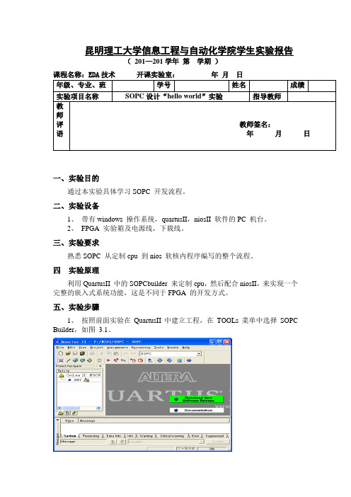
昆明理工大学信息工程与自动化学院学生实验报告( 201—201学年 第 学期 )课程名称:EDA 技术 开课实验室: 年 月 日 年级、专业、班 学号 姓名 成绩 实验项目名称 SOPC 设计“hello world ”实验 指导教师教师评语教师签名:年 月 日一、实验目的通过本实验具体学习SOPC 开发流程。
二、实验设备1、 带有windows 操作系统,quartusII ,niosII 软件的PC 机台。
2、 FPGA 实验箱及电源线,下载线。
三、实验要求熟悉SOPC 从定制cpu 到nios 软核内程序编写的整个流程。
四 实验原理利用QuartusII 中的SOPCbuilder 来定制cpu ,然后配合niosII ,来实现一个完整的嵌入式系统功能,这是不同于FPGA 的开发方式。
五、实验步骤1、 按照前面实验在QuartusII 中建立工程,在TOOLs 菜单中选择SOPC Builder ,如图 3.1。
图3.1 建立工程✧新工程名命名为SOPC。
✧建完这个工程后,首先建一个原理图文件。
✧File->new->Block Diagram/Schematic File,通过此操作建好一个原理图文件,如图3.2所示。
图3.2 建立原理图文件2、定制CPU,参照上图,有一个图标,点击它打开SOPC builder,打开后,在弹出的界面system name后填写名字,这里写的是cpu,自己可以起其他名字,然后点ok,如图 3.3。
图 3.3 SOPC builder 界面1) 构建处理器模块:处理器就是用来做解释程序,运算等操作,图中左栏可以看到,Nios II Processer选项,双击后弹出处理器的属性选项框,我们自己设置参数,来定制所需的处理器,如图 3.4。
图 3.4 处理器属性框✧这里为我们提供了三种类型的CPU,Nios II/e 占用资源最少600-800LEs,功能也最简单,速度最慢。
SOPC系统设计示例

SOPC系统设计示例
1.2 Nios II软件设计流程
SOPC系统设计示例
1.2 Nios II软件设计流程
SOPC系统设计示例
1.2 Nios II软件设计流程
SOPC系统设计示例
1.2 Nios II软件设计流程
SOPC系统设计示例
1.2 Nios II软件设计流程
SOPC系统设计示例
1.1 Nios II硬件系统设计流程
SOPC系统设计示例
1.1 Nios II硬件系统设计流程
SOPC系统设计示例
1.1 Nios II硬件系统设计流程
SOPC系统设计示例
1.2 Nios II软件设计流程
SOPC系统设计示例
1.2 Nios II软件设计流程
SOPC系统设计示例
SOPC系统设计示例
1.2 Nios II软件设计流程
SOPC系统设计示例
1.2 Nios II软件设计流程
SOPC系统设计示例
1.2 Nios II软件设计流程
SOPC系统设计示例
11.2 Nios II软件设计流程
EDA技术
EDA技术
SOPC系统设计示例
1.1 Nios II硬件系统设计流程
SOPC系统设计示例
1.1 Nios II硬件系统设计流程
SOPC系统设计示例
1.1 Nios II硬件系统设计流程
SOPC系统设计示例
1.1 Nios II硬件系统设计流程
SOPC系统设计示例
1.1 Nios II硬件系统设计流程
- 1、下载文档前请自行甄别文档内容的完整性,平台不提供额外的编辑、内容补充、找答案等附加服务。
- 2、"仅部分预览"的文档,不可在线预览部分如存在完整性等问题,可反馈申请退款(可完整预览的文档不适用该条件!)。
- 3、如文档侵犯您的权益,请联系客服反馈,我们会尽快为您处理(人工客服工作时间:9:00-18:30)。
等等。
/articles/linux-xilinx-tutorial/edk101-xup.html
/jevei01/blog/09-06/171878_ec23f.html
/Services/peixun/Xilinx/200902/1910.html
一、硬件平台设计和生成
1.图
2.图
3.
4.
5.
6.
二、生成的硬件平台
生成的VHDL代码
硬件平台即系统的HDL描述。
1.模块连接图:
2.总线连接图:
3.总线接口类型示范:
4.总线连接关系(Bus Interfaces):
5.总线的端口(Ports):
6.总线设备端口地址(Addresses):
三、软件库的生成和编译
软件库里包含的主要是总线设备的驱动程序。
四plication)的代码。
链接和下载:
默认情况下的linker设置:(没有用ddr,仅仅用了xps_bram,并且分配的空间大小是32k):
修改代码:
编译软件代码:
五、下载后的结果
小结
关于XUPV2P上实现SoPC的例子很多,如:
