TKScope嵌入式仿真开发平台讲座(12) TKScope嵌入式智能仿真开发平台率先支持Cortex—MO内核芯片的仿
TKScopeDK10率先支持TI DSP全系列快速仿真、烧写
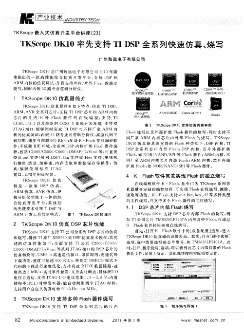
D 0仿 真 器 具 体 支 持 的 Fls K1 a h种 类 如 下 : P 内 核 , DS TI
DS P全 系 列 芯 片 内 部 F a h DS 内 核 , 片 外 部 扩 展 ls ; P 芯
烧 录 o t文 件 ( 对 D P 、 i 件 或 He u 针 S ) Bn文 x文 件 ; 独 执 单 行 擦除、 录 、 解 密 、 烧 加 内存 读 取 和 数 据 保 存 等 操 作 ;仿
K—F ah软 件 轻 松 实 现 在 线 烧 写 。 ls
首 先 , 开 K — l h软 件 中 的[ 备 配 置 ] 项 , 入 打 Fa s 设 选 进
T cp K1 真 器 的设 置 界 面 。其次 , 开 [ 件选 择 ] KS o eD 0仿 打 硬
选 项 , 中 需 要 烧 写 的 芯 片 型 号 , TMS 2 L 2 0 A。此 选 如 30 F 47
T S o e嵌 入 式 仿 真 开 发 平 台 讲 座 (3 K cp 2)
T So e K1 K cp D 0率 先 支 持 T S I P全 快 速 真 、 写 D 系列 仿 烧
广 州致 远 电子 有 限公 司
TKS o eDK1 cp 0是广 州 致 远 电子 有 限 公 司 2 1 0 0年 隆
重 推 出 的 一 款 高 性 能 综 合 仿 真 开 发 平 台 , 持 DS 和 支 P ARM 内核 的仿 真 调试 , 且 支 持 片 内/ 外 F ah的 独 立 并 R ls 烧 写 , 时 内嵌 3 同 2路 专 业 逻 辑 分 析 仪 。
。
1 T c p K1 KS o eD 0仿 真 器 简 介
如 TI 司 芯 片 TMS 2 L 4 7 内部 自带 Fls , 通 过 公 3 0 F2 0 A ah 可
TKScope嵌入式仿真开发平台讲座(57)—AK100Pro-4P量产在线编程器提高产品量产效率

TKScope嵌入式仿真开发平台讲座(57) AK100Pro-4P量产在线编程器提高产品量产效率在线编程具有后期升级方便、节省生产成本、操作灵活等优势,越来越多具有前瞻性眼光的公司转向采用一种全新的编程模式-在线编程。
因此,广州致远电子股份有限公司推出一款量产型AK100Pro-4P在线编程器,能实现4个通道同时在线编程,为工厂量产烧写提供完善的解决方案。
为了适应用户不同的应用需要,AK100Pro-4P在线编程器的每个通道提供4种下载接口:调试接口、USB接口、UART接口和以太网接口。
用户可以根据实际需要,灵活选择不同的下载方式,下载速度可高达数十M每秒。
图1 AK100Pro-4P在线编程器AK100Pro-4P与KFlashPro在线编程软件完美组合,目前已支持高达5000多种MCU和15000多种Flash器件任意组合的在线编程。
并且能实现WinCE、Android、Linux等系统烧写。
图2 AK100Pro-4P同时编程4块WinCE系统板1.功能特点⏹量产型在线编程器,同时编程4通道的目标板;⏹采用高效的烧写算法,极速Flash烧写,节省用户的宝贵的生产时间;⏹支持5000多种主流厂商的MCU,15000多种NorFlash、NandFlash、EEPROM、SPIFlash在线编程;⏹兼容性强,支持4种编程接口烧写(调试/UART/USB/以太网),方便用户使用不同的烧写方式;⏹一键烧写多个器件,可以同时烧写PCB板上的MCU和与之相连的何意Flash器件;⏹支持自动量产烧写,一个板子烧写完毕后,更换板子会自动开始下一板子烧写;⏹创新的云烧录组件,远程在线升级用户固件程序;⏹量身定做烧写方案,如有特殊需求,我们的工程师还可为您量身定制您所需求的烧录方案。
2.产品特色⏹图形化配置界面,方便直观;⏹柔性灵活的NandFlash高级配置;⏹各类BOOT启动代码(支持特殊格式)烧写;⏹WinCE、Android、Linux等系统烧写;⏹支持多通道同步/异步烧写,最大程度提高烧写效率;⏹调试端口及UART接口1000V隔离设计,更好保护用户目标板和编程器;⏹8个用户IO(1000V隔离设计),提供5V@200mA隔离电源输出,方便与自动烧写/测试设备互联;⏹每通道提供一个高速USB 2.0接口,兼容USB1.1;⏹集成100M/10M自适应以太网交换机;⏹每通道提供一个标准的RS232接口,波特率最大支持250kps;⏹定制化软件。
TKScope发布新版KFlashPro软件全面支持S5PV210在线编程

本 文探 讨 T K S c o p e全 面 支 持 S 5 P V2 1 O的 在 线 编 程
能力。
免 使 用 传 统 编 程 器 时 因 各 种 因 素 导 致 烧 写 失 败 而 需 要 重
新 将 芯 片 从 目标 板 取 下 的 问题 。 ( 1 )支持 芯 片 I D号 烧 写 KF l a s h P r o还 支 持 烧 写 时 自动 生 成 序 列 号 , 允 许 指 定
1 支持 S 5 P V 2 1 0的仿 真 器 型 号
TKS c o p e支 持 ¥ 5 P V2 1 0 ( C o r t e x—A8内核 ) 仿 真 器 型 号有 : K8仿 真 器 ; K9仿 真 器 ; DK9仿 真 器 ; DKI O仿 真 器 ; AK1 0 0 P r o仿 真 器 。
借 助 于 KF l a s h P r o , 用户 可 以实 现灵 活 的烧 写 , 以 及 自定 义 各 种 复 杂 的组 合 操 作 。该 软 件 可 用 于 实 际 生 产 , 无 需将 F l a s h芯 片从 目标 板 上 取 下 , 直 接在线 编程 ; 有 效 避
指令 集 , 主频可 达 l GHz , 6 4 / 3 2位 内 部 总 线 结 构 , 3 2 / 3 2 KB的数 据 / 指令一级 缓存 , 5 1 2 KB 的二 级 缓 存 , 可 以实 现 2 0 0 0 DMI P S ( 每秒 运 算 2亿 条 指 令 集 ) 的高性 能运 算 能 力 。
具 。多 年 来 , TKS c o p e一 直 在 研 究 各 大 半 导 体 厂 商 的 内 核 仿真技术 , 不 断 更 新 支 持 新 的 内核 种 类 ; 除 了 传 统 的仿 真 功能 , TKS c o p e在 近 几 年 大 力 发 展 在 线 编 程 技 术 , 支 持 任 意类型的 F l a s h编 程 , 只要 连 接 在 控 制 器 上 的 F l a s h芯 片 ,
TKScope即将推出PK100-4P高效量产型一拖四在线编程器

啜 一 —————曩豳 豳
_ _ ■ r
.
升 级难 易 操 作 复 杂 , 需将 芯片 取下 、 可 随时 刷 新 固件 , 不 损 坏 硬 编程、 贴回 , 损 坏 风 险 极 高 件 , 非 常灵 活 和方 便
2 KF l a s h P r o在 线 编 程 软 件
艇 产 业 技 术
T K S c o p e嵌 入 式 仿 真 开 发 平 台讲 座 ( 5 4 )
_
。。
_
T K S e o p e即将推 出 P K 1 0 0 -4 P高效量产型一拖 四在线编程器
广 州 致 远 电子 股 份 有 限公 司
在人 力 成本 1 3益 升高 和生 产 规 模 不 断 扩 大 的今 天 , 越 来 越 多 电子 厂商 在 寻求 一 种 高 效 的编 程 解 决 方 案 , 以节 省 人力成本 , 提 高产 品 市场 竞 争 力 。传 统 离 线 编 程 器 要 求 在 芯 片 焊 接 到 电路 板 前进 行 预 编程 , 再 贴 片 至 目标 板 。这 种 方式导致生产工序增加 、 芯 片易 于损坏 、 测 试 不 通 过 时 重 新取 下 芯 片 等 问题 , 越 来 越 多具 有 前 瞻性 眼光 的公 司转 向
蘧
叠 桶
图 1
:
KFl a s h P r o在 线 编 程 软 件 将 对 传 统 在 线 编 程 技 术 做 全 新 的定 义 , 突 破 传 统 在 线 编 程 限 制 !简 单 易用 的操 作 界
面, 图形 化 的 配 置 界 面 , 高度柔性 的功能, 支 持 海 量 的
在 板 上
P K1 0 0 — 4 在 线 编 程
【设备指南】TKScope仿真器的硬件接口及连接方法

TKScope仿真器的硬件接口及连接方法TKScope是广州致远电子有限公司2008年隆重推出的一款高性能通用型综合仿真开发平台,支持仿真全系列的8051、ARM、DSP、A VR、C166、C251、C8051F、MX等内核。
TKScope仿真不同类型的内核时,需要选择正确的POD仿真头。
每种类型的POD都是针对内核量身设计的,这样才能保证最佳的仿真性能。
同时,TKScope内嵌64路专业的逻辑分析仪。
下面以K9仿真器为例,介绍TKScope仿真器的硬件接口及连接方法,适用于TKScope 仿真器的型号有:K系列:K3、K5、K8、K9;DK系列:DK5、DK8、DK9。
K9仿真器侧面图1:电源开关:控制电源的连通、断开;电源接口:使用仿真器配套的电源适配器,规格6.3V、内负外正;USB接口:连接电脑的USB接口;RS232接口:预留接口,暂时无功能。
K9仿真器侧面图2:逻辑分析仪接口:连接配套的逻辑分析仪测试线。
K9仿真器侧面图3:该接口共10针,上面的5针是地线;下面的5针的含义分别为: 仿真器监控输出; 逻辑分析触发输出; 未定义,保留接口; 外部输入S0; 外部输入S1。
K9仿真器正面图:电源指示灯: 仿真器供电正常时,此灯点亮; USB 指示灯: 与电脑的USB 接口连接正常时,此灯点亮; CLK/BSY/ERR 指示灯: 仿真器工作状态指示灯。
K9仿真器背面图:ARM/AVR/DSP/C8051F/C166仿真电缆接口8051仿真电缆接口JP4JP3仿真器背面有2个接口(JP3和JP4),通过仿真电缆连接不同的仿真头。
注意:仿真器配套的IDC40仿真电缆属于特殊电缆,用户不能自行替代!POD-8051HS-P84: 8051仿真头, JP3、JP4同时连接仿真电缆; POD-8051BS-P84: Boudout 仿真头, JP3、JP4同时连接仿真电缆; POD-JTAG-ARM-DP20: ARM 仿真头, 只需JP4连接仿真电缆; POD-JTAG-A VR-P10: A VR 仿真头, 只需JP4连接仿真电缆; POD-XDS510P-P14: DSP 仿真头, 只需JP4连接仿真电缆; POD-JC2-C8051F-DP10: C8051F 仿真头, 只需JP4连接仿真电缆; POD-OCDS-DP16: C166仿真头, 只需JP4连接仿真电缆; POD-OneWire-ADI-P2: ADI 仿真头, 只需JP4连接仿真电缆。
TKScope发布XDS100A经济型仿真头配合TKScope K系列仿真器支持DSP仿真

2 X S 0 A功 能特 性 D 10
X 1 0 是 为 了 配 合 DS 0 A TKS o eK 系 列 仿 真 器 、 cp 支 持 DS P仿 真 而 推 出 的 一 款 经济型仿 真 头 , 物 如 图 2 实
P) 一 O 1 ( 8 5 HS—P 4 D 8
可 仿真 不 同厂 商 / 种 封 装 的 8 5 片 各 01芯
可 仿 真 不 同 厂 商 AR 芯 片 , 括 M 包
P OD— T J AG —AR —D 2 AR / M PO M7 ARM9 AR 1 / C E C r / M XS AL / o — 1 t x系 列 e
仿 真 技 术 授 权 , 优 越 的仿 真性 能 如下 : 其
◆ TI 厂 XDS 6 原 5 O类 DS 仿 真 技 术 授 权 , 持 TI P 支 C S 3 3以及 最 新 的 CC v . C v. S 4 0集 成 开 发 环 境 ; ◆ 全 面 支 持 TI公 司 C O O C5 0 / 6 O / 2 O / O O C o O 0MAP / Da n i 系 列 J Vic 等 TAG 接 口的 DS P芯 片 仿 真 ; ◆ US 2 0 Hih S e d 高 速通 信 接 口 , B . ( g p e) 即插 即用 ;
所 示 。 X 1 0 配 合 TK— DS O A
—
_ __ _
So eK 系 列 仿 真 器 完 成 cp
DS P仿 真 , 现 的 功 能 如 实 下 : 持 TI多 种 处 理 器 : 支
TM O 8 、 TM s 2 C5 x 沿2 C2 x 3O 4 、 图 2 P OD—X DS1 0 — 0A
TKScope嵌入式智能仿真开发平台仿真AVR快速入门(英文版)
Guangzhou Zhiyuan Electronics CO., LTD.The revision of historyTable of ContentsChapter 1 TKScope Emulator Introduction (1)1.1 A VR Emulator Support Devices (1)1.2 A VR Emulator Feature (2)1.3 A VR Emulator Support IDE Environment (2)1.4 Connect with TKScope (3)Chapter 2 Simulation A VR in A VR Studio (5)2.1 Install Driver (5)2.2 Install USB Driver (7)2.3 Install JTAGICEmkII driver (9)2.4 Start Debugging (12)2.5 Setting Emulator Parameter (13)2.6 Debug Tools (17)2.7 Stop Debugging (18)2.8 Use A VR Studio Programmer (18)2.9 Exit TKScpe Service (19)Chapter 3 Simulation A VR in IAR (21)3.1 Install Driver (21)3.2 Install USB Driver (23)3.3 Add Driver File (23)3.4 Emulator Parameter Setup (27)3.4.1 Harware Select (27)3.4.2 Main Options (27)3.4.3 Aux options (29)3.4.4 TAP cofig (29)3.4.5 Prog optoins (30)3.4.6 TKScope doctor (32)3.5 Debug (32)3.5.1 Debug Tools (33)3.5.2 Stop Debug (35)Chapter 1 TKScope Emulator Introduction1.1 AVR Emulator Support DevicesTKScope emulator able to support A VR core simulation models are summarized as follows:⏹K Series: K8 / K9⏹DK Series: DK9 / DK10A VR emulator support A VR emulate Atmel A VR device which has JTAG port and all device ISP, the emulator suppor the device as fallow::⏹ATmega16,ATmega16A,ATmega162⏹ATmega165,ATmega165P,ATmega165PA⏹ATmega169,ATmega169P,ATmega169PA⏹ATmega32,ATmega32A,ATmega323⏹ATmega325,ATmega325P,ATmega3250,ATmega3250P⏹ATmega329,ATmega329P,ATmega329PA,ATmega3290,ATmega3290P⏹ATmega64,ATmega64A,ATmega644⏹ATmega645,ATmega6450,ATmega649,ATmega6490⏹ATmega640,ATmega1280,ATmega1281,ATmega2560,ATmega2561⏹ATmega128,ATmega128A,⏹ATmega164P,ATmega164PA,ATmega324P,ATmega324PA,ATmega644P,ATmega644PA,ATmega1284P⏹AT90CAN32,AT90CAN64,AT90CAN128⏹AT90USB646,AT90USB647,AT90USB1286,AT90USB1287⏹ATmega48,ATmega48A,ATmega88,ATmega88A,ATmega168,ATmega168A⏹ATtiny13,ATtiny13A⏹ATtiny2313,ATtiny2313A,ATtiny4313⏹ATtiny25,ATtiny45,ATtiny85⏹ATtiny24,ATtiny24A,ATtiny44,ATtiny44A,ATtiny84,ATtiny84A⏹ATtiny261,ATtiny261A,ATtiny461,ATtiny461A,ATtiny861,ATtiny861A⏹ATtiny87,ATtiny167⏹AT90PWM2,AT90PWM2B,AT90PWM216⏹AT90PWM3,AT90PWM3B,AT90PWM316⏹AT90USB82,AT90USB162⏹ATxmega64A1,ATxmega128A1,⏹ATxmega64A3,ATxmega128A3,ATxmega192A3,ATxmega256A3⏹ATxmega256A3B,⏹ATxmega16A4,ATxmega32A4,⏹ATxmega16D4,ATxmega32D4,⏹ATxmega64D3,ATxmega128D3,ATxmega192D3,ATxmega256D3More devices will be support in the near future.TKScope emulate A VR device use the POD is: POD-JTAG-A VR-P10.Figure 1-1 POD-JTAG-AVR-P101.2 AVR Emulator F eatureTKScope A VR emulator feature:⏹USB2.0(High Speed)communication interface,fast prommning speed,save yourdeveloping time;⏹JTAG programming speed is ATMEL‟s JTAGICE mkII 2.8 times;⏹ISP(1MHz clock)speed is ATMEL’s JTAGICEmkII 4.7 times;⏹Support K-Flash programming software,support fast speed promming;⏹Support programming Flash、EEPROM、Fuse、LockBits;⏹Support all MEGA device JTAG programming and debuge;⏹Support all debugWIRE device debug;⏹Support ISP programming;⏹Support XMEGA device PDI programming and debuge;⏹Auto detect A VR Studio Version,you can use all A VR Studio Version did NOT needchange driver;⏹Support High level language and assembler language debuge;⏹Support data break point and no limit flash break point;⏹Support dynamic break point, you can set and clear break poit when the target isrunning;⏹Support code modify, Make you debuge more convenient;⏹Hardware selftest;⏹Code and data cache, i mprove the debugging performace;⏹Emulator can follow the target device volatage.1.3 AVR Emulator Support IDE EnvironmentTKScope simuation A VR device support multiple IDE environment, Engineers can be choise the familiar IDE, support the IDE as fallows:⏹TKStudio, Zhiyuan company, Chinese/english environment, multi-core compiling/debugging, powerful built-in editor⏹A VR Studio, Atmel Corp., English environment, Can be plug-in GCC comlier.⏹IAR, IAR Corp, Engish, multi-core compiling/debugging.Figure 1-2 Support IDE Environment1.4 Connect with TKScopePOD_JAG_A VR_P10 has 2 ports,40P connect to Emulator‟s JP4,10P connect to your target (JTAG interface).ADP_A VR_P10_P6 use in ISP proggrame and debugWIER simulation(support in the near future), Connect the J3(10P) to POD_JTAG_A VR_P10,and J4 connect to your target.JTAG and ISP interface the same as Atmel‟s define, as Figure 1-3.Figure 1-3 JTAG & ISP InterfaceWe suggest use the 6PIN ISP connects when you use the debugWIRE simulation. Notice: the Adaptor RESET pint connects to TMS, NOT nSRST!The APD_A VR_P10_P6 connect asFigure 1-4.Figure 1-4 ADP_AVR_P10_P6 signal connectTips: We can see when use PDI signal Vcc, GND, PDI_CLK is the same with ATMLE‟s define, but PDI_DATA is use pin 4, NOT pin 1, you need connect you target board pin1 and pin4 to use the Adaptor.Figure 1-5 PDI Hardware connectChapter 2 Simulation AVR in AVR Studio2.1 Install DriverThe Driver is only for A VR Studio, befor you install this driver, sugest you install A VR Studio (Support A VR Studio 4.13 or later), Double click “Setup_TKScope_A VRStudio.EXE”, the system pop-up dialog box as show in Figure 2-1, Click “Next” and to continue.Figure 2-1 Install DriverYou may install the driver in the path where you want to.Figure 2-2 Select install pathClick “Next” and go on until the driver install finish. Afer the driver setup finish, you can see the start menu has “A VRStudio with TKScope”& “Uninstall A VR Studio with TKScope,”“A VRStudio with TKScope” is use to startup A VRStudio will TKScope Service, Use TKScope in A VR Studio Emulate A VR use this to start (before you start it, May sure you had turn on the emulator and connect the emulator to your computer through USB). “Uninstall A VR Studio with TKScope” is to unstall this driver.Figure 2-3 Start menu after Install driverAfter install the Drivers, Suggest user install the Mrosoft VC8 run lib.Double “vcredist_x86_en.exe”, Sytem will dislay Figure 3-3 the dialog box.Click [next].Figure 2-4 Install VC8 Run LibIn the License Terms dialog, choise[I have read and accept the license terms], then click Install to start setup up.Figure 2-5 Accept the license terms and Install2.2 Install USB DriverWhen you connect the TKScope emulator whith you computer through the USB interface the first time, the system will pop-up dialog box as shown in Figure 2-6.Figure 2-6 New Hardware Installation WizardSelect [Install from a list or specific loaction(Advanced)] options inFigure 2-6, click [Next], The system will pop-up dialog box as shown in.Figure 2-7.Figure 2-7 Select Drive BoxIn Figure 2-7, click [Browse], open the dialog box as shown in.Figure 2-7. Find the driver files in TKScope_A VRStudio installation directory (example is C:\Program Files\ TKSCP_SRV_for_A VRStudio\Driver\TKScope K Driver\TKScopeK\WinXP), click [OK].Figure 2-8 Designated DriverAfter the driver installed, system will pop-up dialog box as shown in Figure 2-9, click [finish]to finish.Figure 2-9 New Hardware Installation Completed2.3 Install JTAGICEmkII driverPlease make sure you has install USB driver when you install A VR Studio,When you install A VR Studio, Select Install/upgrade Jungo USB Deiver(default install), as Figure 2-10.Figure 2-10 Instal AVR Studio USB driverAfter Install it, you can fine the USB driver int the A VR Studio install path(for examplr: C:\Program Files\Atmel\A VR Tools), there is a folder name usb, this folder is A VR Studio USB driver. If you had not install USB driver when install A VR Studio, Please Install A VR Studio again.Befor startup the IDE you should turn on the emutor and connect with your computer through USB interface, click “A VR Studio with TKScope”, The first time need install JTAG ICE mkII Driver, as shown in Figure 2-11, in the dialog Choise [Install from a list or specific location(Advanced)], Click [Next].Figure 2-11 Install JTAG ICE mkII driverChoise [Include this location in the search], In the explorer Select A VR Studio Install path, the USB folder, clinck [Next].Figure 2-12 Select install pathWaiting the System install finish, you can see the Figure 2-13 dialog box; click [Finish] to finish the driver install.Figure 2-13 Finish installAfter install, you can see the taskbar the icon, as Figure 2-14, When A VR Studio communicate with TKScope, this icon wil be flash.Figure 2-14 AVR Studio TKScope Service2.4 Start DebuggingIn A VR Studio, after builded success, click “Start Debug”, Figure 2-15, A VR Studio will setting the emulator parameter and made the target device enter debug mode.Figure 2-15 Start DebugAfter enter debug mode, you can see the debug widows, as Figure 2-16, and this window can be open throgh the menu “View -> Toolb ars”.Figure 2-16 Debug Window2.5 Setting Emulator ParameterIn the debug mode, you can select the [Debug] menu and choise [JTAGICE mkII Options] toopen the emulator parameter setting dialog, sehown as in Figure 2-17.Figure 2-17 Debug parameter SettingRegetor windowCode WidowInformation WindowIO WindowDebug toolbarsThe Setting has 4 tags, the [Connect] tag is use to setting connect options, use to setting JTAG frequency and daisy chain, before enter debug mode, A VR Studio will set this parameter. Notice change JTAG frequency should be slower than 1/4 of target frequency.The [Disable debugWIRE] boton is effect when use debugeWIRE simulation, for disable debugeWIRE function and reable ISP, when press this botton, IDE will exit debuge mode.Figure 2-18 ConnectionThe second tag use setting the debug options, as shown in Figure 2-19.Figure 2-19 DebugGeneral group items function as Table 2.1.Table 2.1 General Debug OptionProgram Startup is setting the program entrance fution and Boot Reset fuse set not correct warnig.Program Download is choise wether program flash when enter Debugging, Suggest select [Alwasys reprogram].The third tag is tatus Options, in this can be see the emulator and targer device inforamtion.Figure 2-20 StatusThe fourth tag is PWM options, only for AT90PWM device. You can control the PSC controller and Analog Comparator whether run when the target in the stop mode when in debuge.Figure 2-21 PWM2.6 Debug ToolsA VR Studio Debug tools as Figure 2-22.Figure 2-22 Debug ToolsStart DebuggingStope DebuggingRunBreakShow Next StatementStep IntoStep OverStep OutRun to CursorAuto StepToggle BreakpointRemove all Program BreakpointsQuick watchToggle Watch WindowToggle Register WindowToggle Memory WindowToggle Disassembler Window2.7 Stop DebuggingWhen user want to stop debugging, Press .2.8 Use AVR Studio ProgrammerIf you want to use A VR Studio programmer to program the target device, click the [display the …connect‟ dialog], then the IDE show as in Figure 2-24 dialog,Select [JTAGICE mkII], Click [Connect](Notice: Before you connect the programmer, you should stop debugging).Figure 2-23 Coonect AVR ProgrammerFigure 2-24 Select AVR ProgrammerConnect with emulator successful system will pop-up the Figure 2-25 dailog. In the [Device and Sigature Bytes] select the target device; [Programming Mode and Target Settings] select the programming mode.Notice: when use ISP mode needs the Addapt P10-P6, connect whith the target device use the IDC6 cable.Figure 2-25 Program DialogIn the programming dialog other tags, you can program the Flash, EEPROM, Fuse, Lock bits and read the calibrate bytes and so on.2.9 Exit TKScpe ServiceWhen you stop debugging and leave programming, if you want to use IAR,K-Flash, you should exit the TKScope service, then other software can use the emulator. Right click the service icon, select [Quit], and then you can use other software.Figure 2-26 Exit TKScope ServiceChapter 3 Simulation AVR in IAR3.1 Install DriverIn the IAR use TKScope emulator should install the driver.Double Click “TKScopeSetup_A VR8.EXE”, System will pop-up the Figure 3-1 daigure box, click [Next] to install.Figure 3-1 Install Emulator DriverThe driver can be installed in the path which you want to as Figure 3-2.Figure 3-2 Select Install PathAfter install the Drivers, Suggest user install the Mrosoft VC8 run lib.Double “vcredist_x86_en.exe”, Sytem will dislay Figure 3-3 the dialog box.Click [Yes], system will finish setup automation.Figure 3-3 Install VC8 Run LibNow the emulator drivers install finish.In the install folder(this example is “D:\TKS\TKScope”), you can see the .Dll files, As Figure 3-4.Figure 3-4 Driver FilesAfter Setup the driver, you can see the dll files in the folder, the driver file as Table 3.1Table 3.1 Driver for IDE3.2 Install USB DriverWhen you connect the TKScope emulator whith you computer through the USB interface the first time, you need to install the TKScope USB driver, how to install the driver you can reference the 2.2Install USB Driver, and you also you fine the driver files in the TKScopeSetup_A VR8.EXE install path.3.3 Add Driver FileAfter install the driver , Open a project wich buided finish, As Figure 3-5, choise the Project menu, Click [Option] enter the Project option.Figure 3-5 IAR EnvironmentIn the setting dialog, choise [Debugger] option, in the [Setup] window setup as Figure 3-6 [Driver] choise [Third-Party Driver], select [Run to main].Figure 3-6 Select DriverChoise [Third-Party Driver], as Figure 3-7.Click , add emulator driver.Figure 3-7 Third-Party DriverAs Figure 3-8, choise“TKSCP_DRV_A VR8_for_IAR_v5.dll”, click “Open” button to add the driver file.Figure 3-8 Select IAR Driver FileAfter setting driver file as Figure 3-9, click “OK” button finsish setting.Figure 3-9 Finish Driver LoadTKScope emulator parmeter must set correct, otherwise the emulator can‟t work! as Figure 3-10, click menu ”TKScope” choise ”Setup”, then enter the setup dialog.Figure 3-10 IDR After Add DriverSelect the [TKScope] menu, click [Settings] enter TKScope emulator setting interface asFigure 3-11.Figure 3-11 Emulator SettingIn Figure 3-11, click the left side of the various options, the system will pop-up the appropriate settings interface, while the right side of the information prompt box will appear the specific meaning of the various setting.Message Box3.4 Emulator Parameter Setup3.4.1 Harware SelectClick Figure 3-11 the [Device & hadware type], enter the setting information of Figure 3-12 the setting interface.Figure 3-12 Device & hardware SelectChoise the chip which you want to emulator, In the device list, Click [OK] return to Figure 3-11 [Search], system will auto serch the emulator, As Figure 3-13 Search, Press [OK] to save the settings.Users also can choise the device name and the emulator which you use.Figure 3-13 Search3.4.2 Main OptionsPress Figure 3-11[Main Options], enter Figure 3-14 the main option interface.Figure 3-14 Main Options1. CacheCache Config is user to Solution the Screen and Emulator Speed.If choise the cache, screen will be bush afer user pograming is running, it can be faster the dissplay spped, but if a operation can course the data change may not display in time.If not choise cache, user any operate will course the data brush the screen, but the speed will be slow.[cache code]: Use Code Cache.[cache data]: Use Data Cache.Suggest user set as the default settings, Only choise [cache code].2. Break[use software break point]: Select ths item, can use no limit flash breakpoints.3. Clock Mode[auto speed]: Auto selects the enable highest speed.[fixed speed]: Use the user input JTAG frequre.[Jtag]: Choise JTAG frequre, Only in the fixed speed effect. In order to may theTarget device run Correct, JTAG Frequre should be slow than the system clock 1/4 or more slowly.4. Hardware reset options[user SRST]: Use the Harware System Resset nSRST.[user TRST]: Use the Harware JTAG Reset nTRST, 8-bit A VR device has not JTAG reset pin, so this setting is reserve.[reset hold]: Select rese hold time in ms.[reset restore]:Select reset restorer time in ms.3.4.3 Aux optionsClick Figure 3-11 [Aux options], Enter the Aux Setup as Figure 3-15.Figure 3-15 Aux Setup[Program config data]: After downloaer program config the Fuse, As the A VR device Fuse Config is can be save after chip erase, so this option is only select when use K-Flash in program, In the mulat not program config to save time.[Stop Timer in Debug]: Whether the device in stoped mode timers running.[Use SPI when prog flash]: Whether use ISP program flash (Only in K-flash affect, use the ADP-A VR-P10-P6 adapter).3.4.4 TAP cofigClick Figure 3-11 [TAP config], Enter the Figure 3-16 TAP setting dialog.Figure 3-16 TAP SetupTAP configations to setup the JTAG chian, include number of devices IR length, active device.It's important to setup when there is unkown device in the JTAG chian. Normally, [Automatic Detection] option will be ok.[Devices list]: List all devices in scan chain; include name, IR length &.idcode.[IDCODE]: The idcode of the device, for add, update operations.[name]: The name of the device.[IR length]: The IR length of the JTAG device.[Automatic Detection]: Setup scans chian automatically.[Manual Configuration]: Setup manually.[Add]: Add a new device in the devices list.[Delect]: Delect a device in the device list.[Update]: Update the device in the device list.[Up]: Move the selected device upward.[Down]: Move the selected device downward.3.4.5 Prog optoinsProgram Config has 4 tags, the first tag is Fuse, Fuse seting, As Figure 3-17, diference device has diference Fuse bits, how to setting this Fuse please refernce the datashet of device.Figure 3-17 Configure FuseThe second tag is Lock, Lock bits settings, use to progaram Lock bist as Figure 3-18.Figure 3-18 Configure LockThe last tag is use to read the RC oscillator calibrate bytes and write the calibrate byte to Flash or EEPROM.Figure 3-19 Configure CalThe dialog has 6 bottoms, the funtion of buttons as Table 3.2.Table 3.2 Configure Button function3.4.6 TKScope doctorClick Figure 3-11 [TKScope doctor], enter the TKScope doctor.TKScope doctor's function is very powerful, detecting own hardware init, USB communication, hardware reset, and reading A VR core ID 100000 times.Notice: Use the TKScope doctor need in JTAG Mode, NOT use the ADP-A VR-P10-P6 adapter!Figure 3-20 TKScope doctor3.5 DebugAfter config finish, now you can start debugging.3.5.1 Debug ToolsIn IAR IDE, after driver installs and setup parameter, you can start debugging, the debug tools as Figure 3-21.Figure 3-21 Debug ToolsDebugMakeToggle BreakpointResetBreakStep OverStep IntoStep OutNext StatementRun to CursorGoStop DebuggingAfter settup drivers and parameter, As Figure 3-22 return to IAR IDE, click “Make”, then press “Debug” in the debug mode.MakeDebuFigure 3-22 Setup FinishAfter enter debug environment, as Figure 3-23, Click ”View” menu, Select ”Register”, you can see the register, others are the similarity.Figure 3-23 Debug WidowsIn IAR environment, you can modify the use code in memory window, and you can set breakpoint when the target device is running.3.5.2 Stop DebugIf you want to stop debug, Click button can exit the debug mode.。
TKScope嵌入式仿真开发平台讲座(56) 使用AK100Pro-4P提高Android系统的Flash量产编程效率
协 议 。通 过 US B高 速 接 口, 最 大 的 数 据 传 输 速 度 可 高 达
数十兆 。
1 产 品 Байду номын сангаас 色
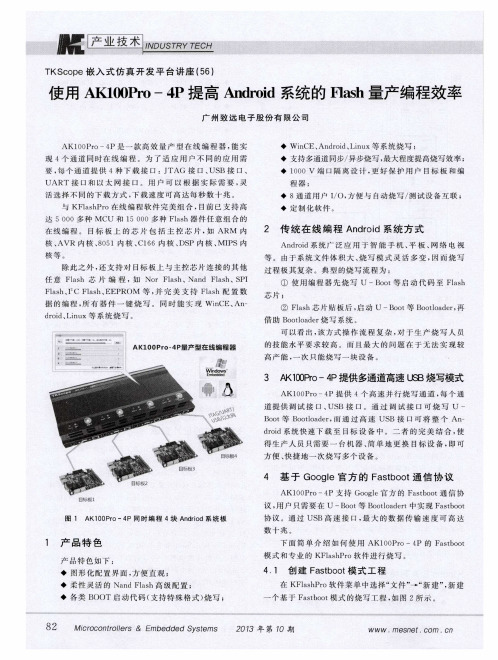
产 品特色如下 : ◆ 图形化配置界 面 , 方便直观 ; ◆ 柔 性 灵 活 的 Na n d Fl a s h高 级 配 置 ;
借助 B o o t l o a d e r烧 写 系 统 。
可以看出 , 该方式操作 流程复 杂 , 对 于 生 产 烧 写 人 员 的 技 能 水 平要 求 较 高 。而 且 最 大 的 问 题 在 于 无 法 实 现 较
高产能 , 一 次 只 能烧 写 一块 设 备 。
3 A K 1 0 0 P r o 一4 P提供 多通道高速 U s B烧写模式
2 0 1 3# - r 4 1 0期
w WW
.
me s n et . c or n o n
兰 _ y 巫
4 基于 G o o g l e官 方 的 F a s t b o o t 通信 协 议
AK1 0 0 P r o一4 P支 持 Go o g l e官 方 的 F a s t b o o t通 信 协 议, 用 户 只需 要 在 U —B o o t 等B o o t l o a d e r t中 实现 F a s t b o o t
等 。由 于 系统 文 件体 积 大 、 烧 写模 式灵 活多变 , 冈 而 烧 写
过 程 极 其 复 杂 。典 型 的烧 写 流 程 为 :
除此 之 外 , 还 支 持 对 目标 板 上 与 主 控 芯 片 连 接 的其 他 任意 F l a s h 芷 : 片编 程 , 如 No r F l a s h 、Na n d F l a s h 、S P I F l a s h 、 I C Fl a s h 、 E EP ROM 等 , 并完 美 支持 F l a s h配 置 数
TKScope发布富士通ARM芯片完整编程和仿真组件
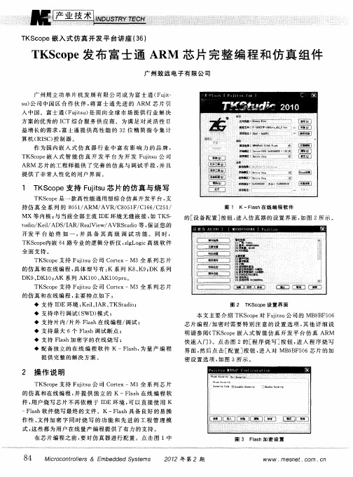
1 T cp KS o e支 持 F js ui u芯 片 的仿 真 与 烧 写 t
T So e 一 款 高 性 能 通 用 型 综 合 仿 真 开 发 平 台 , K cp 是 支 持 仿 真 全 系 列 的 8 5 / R A / 8 5F C 6 / 2 1 0 1 A M/ VR C 0 1 / 1 6 C 5 /
本 文 主要 介 绍 TKS o e对 Fuis cp j u公 司 的 MB B 5 6 t 9 F 0 芯 片 编 程 / 密 时 需 要 特 别 注 意 的 设 置 选 项 , 他 详 细 说 加 其
明请 参 阅 《 K cp 嵌 入 式 智 能 仿 真 开 发 平 台仿 真 A M T Soe R 快速入 门》 。点 击 图 2的 [ 序 烧 写 ] 钮 , 入 程 序 烧 写 程 按 进 界 面 , 后 点击 [ 置 ] 钮 , 入 对 MB B S 6 片 的 加 然 配 按 进 9 F0 芯
全面支持 。
TKS o e支 持 F j s cp ui u公 司 C re t o tx—M3全 系 列 芯 片
的 仿 真 和 在 线 编 程 , 体 型 号 有 : 系列 K 、 ; K 系 列 具 K 8 K9 D
DK9 DK1 AK 系列 AK1 0、 、 0; 0 A的文 件 。K — l h具 备 良好 的易 操 ls 软 Fa s
作 性 、 件 加 密 字 同 时 烧 写 的 功 能 和 先 进 的 工 程 管 理 模 文 式 , 些 都 为用 户在 线 量 产 编 程 提 供 了有 力 的支 持 。 这 在 芯 片 编程 之 前 , 对 仿 真 器 进 行 配 置 。点 击 图 1中 要
图 3 Fa h加 密 设 置 ls
TKScope嵌入式仿真开发平台讲座(20)K-Flash发布嵌入式编程组件支持第三方程序调用

TKScope嵌入式仿真开发平台讲座(20)K-Flash发布嵌入式编程组件支持第三方程序调用广州致远电子有限公司【摘要】@@ K-Flash是一款用于在线Flash的烧写,支持TK-Scope系列硬件,具有文件烧写与校验、数据擦除、数据查空和数据读取等功能的软件.【期刊名称】《单片机与嵌入式系统应用》【年(卷),期】2010(000)010【总页数】2页(P84-85)【作者】广州致远电子有限公司【作者单位】【正文语种】中文K-Flash是一款用于在线Flash的烧写,支持TKScope系列硬件,具有文件烧写与校验、数据擦除、数据查空和数据读取等功能的软件。
从版本V3.40开始,K-F lash开放命令行功能,支持第三方用户程序直接调用。
基于这种嵌入式组件,K-Flash用户可以在自己的程序(VC、VB或命令行)中直接调用K-Flash完成在线烧写Flash。
由于用户获得了K-Flash的控制权,因此用户在程序中可以灵活地对目标板上的各种Flash进行任意操作,实现一般编程器不能支持的自定义烧写功能。
例如,在有安保要求的产品中,型号相同的产品个体中Flash的代码可能不同。
原因是每个产品个体的密码/序列号不同,因此每个产品个体都要形成不同的代码。
因此用户可以用软件来生成每个个体的代码,然后控制K-F lash完成对每个产品个体的烧写。
由于使用用户自己编写的软件来完成烧写操作,因此在整个烧录过程中密码/序列号都隐藏在用户的软件中,与操作人员完全隔离,可以满足安保产品的保密要求。
与K-Flash配套的TKScope系列硬件同时由广州致远电子有限公司提供,支持全系列的8051、ARM、DSP、AVR、C8051F、C166、C251、MX等内核的内部Flash烧录,同时也支持全部NOR、NAND、SPI、I2 C等外部Flash的烧写。
K-F lash配合TKScope支持烧写的内核种类如下:ARM内核:ARM 7/ARM9/ARM 11/Cortex-M 0/Cortex-M 1/Cortex-M3/Cortex-A8/Cortex-A9/XScale等全系列芯片;DSP内核:TI公司C2000/C5000/C6000/OMAP/DaVinci等全系列芯片;AVR内核:Atmel公司MEGA、TINY、XMEGA等全系列芯片;C166内核:Infineon公司XC166/XE166/XC2000等全系列芯片;C8051F系列:Silicon Labs公司全部C8051F系列芯片。
TKScope发布在线编程组件率先支持STM32内部配置数据

3 编 程 配 置 数 据 操 作 示 例
本文基 于 S TM3 F 0 VC介 绍 如 何 在 TKS o e下 灵 2 17 cp
AVR等 内核 仿 真 ;
◆ DK 系 列 , DK5 DK8 DK9 DK1 , 持 ARM 、 、 、 、 0 支
m e o y m ir c n r le s) m r e o o to lr ) 。
◆ s TM3 F O / 0 x 2 1 5 J 7 x全 部 型 号 ;
8 4
Mco o t l r & E e d dS se s irc nr l s oe mb d e y tm
21 年第1 0 7 0期
现 代 码 保 护 、 设 功 能 配 置 等 , 成 为 最 迫 切 和 最 难 实 现 外 却
的需 求 。
2 支 持 编 程 S M3 T 2配 置 数 据 的 功 能 亮 点
T cp 支 持编 程 S M3 KSo e T 2配 置数 据 , 优异 特性 如 下 : 其
◆ 全面支持 S TM3 2所 有 配 置 数 据 的编 程 ; ◆ 全 面支 持 S TM3 F1 x S 2 0 、 TM3 F 2 S 2 、 TM3 1 2 系
时 间 和 精 力 编 写 和调 试 代 码 。
◆ 仅 仅 使 用 J AG S T / WD 调 试 接 口 , 需 任 何 其 他 外 无
部接 口 ; ◆ 具 有 极 强 的 人 性 化 界 面 、 灵 活 的 操 作 接 口 以 及 极 极 舒 适 的用 户 体 验 ;
作 为 国内嵌入 式 仿 真器 行业 中具 有影 响 力 的公 司 , TKS o e嵌 入 式 智 能 仿 真 开 发 平 台率 先 提 供 了 完 整 的 解 cp
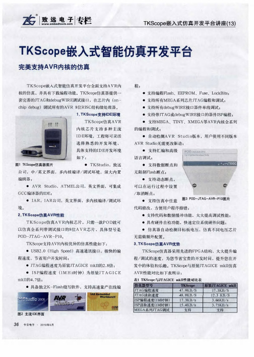
TKScope嵌入式智能仿真开发平台
通 用编 程器
U / AN 议分析仪 SB C 协
今日电子 .2 1 ̄6 37 0o . 8
从对 比表 中可以 看 出,TKSC e 多个 方面 比原装 的 0P 在 J TAG C I有更强的仿真性能 ,而且T cp 仿真器 I E mk I KS o e 保证不断的 、及时的支持新型器件的编程和调试 。 4 在线编程K F a h 。 - ls 软件
・ 设备配置 :配置仿真 器类型 、芯片参数 、F a h ls 编 程算法等 ;
支持 支持 支持 ( 环境 ) I AR 支持 ( R I 环境 ) A
支持 支持 不支持 不支持
即可 。
・ 新建 :新建一 个空 白工程文 件 ;
・ 打开工程 :打开一个指定的工程 ; ・ 保存工程 :保存一个工程到指定的路径 ;
・ 另存工程 :把 当前配置 另存到指定的位置 ;
・ 支持片 内Fah ls 和片 ̄ Fah l ls 烧写 ; ' ・具备烧 写校验功能 ,验证烧写是否正确 ;
5小结 .
本文主要介绍了TKS o e c p 仿真AVR内核的特性和优 势,以及 在线 编程软件 K- ls 的性能 。TK cp 在支持 Fa h S oe AVR内核方面会不断 的升级 ,保证支持最新版本的I 环 DE
境 ,保证支持新增 的器件 型号 。TKS o e c p 仿真AVR内核
芯片的具体使用方法 ,读者可登录TK c p 网站下载中英 S oe 文双语版使用指南 。 除此 之外 ,TKSC Pe O 仿真 器还 可 以支 持ARM 、
・ 具 有 独 立 的数 据 擦 除功 能 ,可指 定 扇 区进 行 擦 除 ,操作更快捷 ;
据;
TKScope嵌入式智能仿真开发平台讲座(12)TKScope嵌入式智能仿真开发平台

TKScope嵌入式智能仿真开发平台讲座(12)TKScope嵌入
式智能仿真开发平台
佚名
【期刊名称】《今日电子》
【年(卷),期】2010(000)005
【摘要】@@ TKScope嵌入式智能仿真开发平台支持全部ARM内核芯片的仿真,如ARM7/ARM9/ARM11/Cortex-MO/Cortex-M1/Cortex-M3/XSCALE
等.FKScope仿真器通过软件升级,不断地、及时地支持各个半导体公司新增的内核种类和芯片型号.
【总页数】2页(P42-43)
【正文语种】中文
【相关文献】
Scope嵌入式智能仿真开发平台完美支持AVR内核的仿真 [J],
Scope嵌入式仿真开发平台讲座(12)TKScope嵌入式智能仿真开发平台率先支持CortexM0内核芯片的仿真 [J], 广州致远电子有限公司
Scope嵌入式仿真开发平台讲座(13)TKScope嵌入式智能仿真开发平台完美支持AVR内核的仿真 [J], 广州致远电子有限公司
Scope嵌入式仿真开发平台讲座(10)TKScope DK9嵌入式智能仿真开发平台独创的技术引领DSP与ARM开发工具的新模式 [J], 广州致远电子有限公司
Scope DK9嵌入式智能仿真开发平台独创的技术引领DSP与ARM开发工具的新模式 [J],
因版权原因,仅展示原文概要,查看原文内容请购买。
TK Scope嵌入式仿真开发平台讲座(57) AK100Pro-4P量产在线编程器提高产品量产效率
TK Scope嵌入式仿真开发平台讲座(57) AK100Pro-4P量
产在线编程器提高产品量产效率
佚名
【期刊名称】《单片机与嵌入式系统应用》
【年(卷),期】2013(13)11
【摘要】在线编程具有后期升级方便、节省生产成本、操作灵活等优势,越来越多具有前瞻性眼光的公司转向采用这种全新的编程模式。
冈此,广州致远电子股份有限公司推出一款量产型AKl00Pro-4P在线编程器,能实现4个通道同时在线编程,为工厂量产烧写提供完善的解决方案。
为了适应厢,
【总页数】2页(P84-85)
【关键词】在线编程;编程器;产品;生产成本;编程模式;通道
【正文语种】中文
【中图分类】TP368.1
【相关文献】
1.使用AK100Pro-4P提高Android系统的Flash量产编程效率 [J], 广州致远电子股份有限公司
2.AK100Pro-4P量产在线编程器提高产品量产效率 [J], 广州致远电子股份有限公司
Scope嵌入式仿真开发平台讲座(12)TKScope嵌入式智能仿真开发平台率先支持CortexM0内核芯片的仿真 [J], 广州致远电子有限公司
Scope嵌入式仿真开发平台讲座(54) TKScope即将推出PK100-4P高效量产
型一拖四在线编程器 [J],
Scope嵌入式仿真开发平台讲座(53) TKScope的在线编程云系统提升汽车仪表盘量产烧写效率 [J],
因版权原因,仅展示原文概要,查看原文内容请购买。
YH-AStar高性能实时仿真平台

YH-AStar高性能实时仿真平台
姚益平;蒋志文;鄢来斌;李钢
【期刊名称】《计算机仿真》
【年(卷),期】2003(000)0z1
【摘要】仿真计算机是大型复杂动力学系统研究、设计、试验、评估不可缺少的重要工具,基于通用计算机和Windows NT操作系统进行实时半实物仿真一直是仿真用户企盼的愿望.该文介绍了基于Intel平台和Windows NT操作系统的高性能实时半实物仿真平台YH-AStar的研制目标、系统结构与组成,阐述了YH-AStar 软硬件部分的主要功能.
【总页数】3页(P219-220,224)
【作者】姚益平;蒋志文;鄢来斌;李钢
【作者单位】国防科技大学计算机学院,湖南,长沙,410073;国防科技大学计算机学院,湖南,长沙,410073;国防科技大学计算机学院,湖南,长沙,410073;国防科技大学计算机学院,湖南,长沙,410073
【正文语种】中文
【中图分类】TP368
【相关文献】
1.电磁机电混合实时仿真平台实用化技术研发与实现:(一)混合实时仿真数字量接口[J], 欧开健;胡云;梁旭;周仲晖;张树卿;蔡泽祥;管霖
2.基于高性能计算仿真平台的天安门LED屏设计仿真 [J], 曾宇;刘东旭;陈元生
Scope嵌入式仿真开发平台讲座(22)TKScope隆重推出AK200系列高性能仿真器 [J], 广州致远电子有限公司
4.基于实时内核的双起升双吊具桥吊实时仿真平台 [J], 马晓飞;徐为民;褚建新;周贤文
5.高性能网络多级交换结构实时调度方法仿真 [J], 邹小花;夏容
因版权原因,仅展示原文概要,查看原文内容请购买。
徐州工程学院苯胺智能仿真工厂建设规划思路与进展

徐州工程学院苯胺智能仿真工厂建设规划思路与进展
王菊;唐华;堵锡华
【期刊名称】《山东化工》
【年(卷),期】2017(046)009
【摘要】近年来,化工过程产业相关领域创新人才资源与技术投入双重不足的矛盾逐渐显现,使得化工过程产业逐步面临转型、升级的挑战,需要通过技术和人才的创新驱动,来解决进一步发展中的深层次问题.苯胺智能仿真工厂项目基于互联网全面开放,涵盖“半实物仿真工厂”和“虚拟现实仿真工厂”两个组成部分.本文详细阐述了苯胺智能仿真工厂项目建设目标与总体规划、实施思路与特点及目前项目建设进展情况.
【总页数】3页(P161-163)
【作者】王菊;唐华;堵锡华
【作者单位】徐州工程学院化学化工学院,江苏徐州221018;徐州工程学院高教研究与评估中心,江苏徐州 221018;徐州工程学院化学化工学院,江苏徐州221018【正文语种】中文
【中图分类】TQ246.3
【相关文献】
1.纳米结构聚苯胺及聚苯胺纳米复合材料的研究进展 [J], 张悦;汪广进;孙爽;潘牧
2.高性能环件辗轧成形智能仿真优化新思路与研究进展 [J], 郭良刚;王凤琪;梁磊;王艺凡;黄维鑫
3.苯胺缩合生产二苯胺催化剂的研究进展 [J], 樊太山;梅来宝
Scope嵌入式智能仿真开发平台讲座(12)TKScope嵌入式智能仿真开发平台[J],
5.N-甲基苯胺和N,N-二甲基苯胺合成研究进展 [J], 徐龙;祝一锋;李小年
因版权原因,仅展示原文概要,查看原文内容请购买。
Macraigor公司Flash编程芯片支持工具
Macraigor公司Flash编程芯片支持工具
佚名
【期刊名称】《电子产品世界》
【年(卷),期】2005(000)04B
【摘要】Macraigor Systems LLC公司宣布其OCDemon Flash Programmer 现支持若干新flash芯片系列。
所有OCDemon产品与OCDemon Flash Programmer一起使用时都支持部件编程。
OCDemon Flash Programmer为在flash部件上执行多种编程和调试功能提供了图形用户界面(GUI)。
该GUI界面为与目标CPU相连的flash内容进行编程提供了高水平的交互功能。
【总页数】1页(P55)
【正文语种】中文
【中图分类】TP319
【相关文献】
1.Actel推出第三代以Flash为基础器件可编程逻辑方案和启动套件全新单芯片ProASlC3器件会将Flash应用推向市场主流 [J],
Scope即将隆重发布KFlashPro在线编程软件——二十年深耕打造专业的Flash在线编程工具 [J], 广州致远电子股份有限公司
3.监控应用系统的编程支持工具 [J], 陈建民
Scope嵌入式仿真开发平台讲座(3) 嵌入式系统在线编程软件K-Flash快速、稳定地编程任意类型Flash [J],
Scope嵌入式仿真开发平台应用(3)嵌入式系统在线编程软件K-Flash——快速、稳定地编程任意类型Flash [J],
因版权原因,仅展示原文概要,查看原文内容请购买。
- 1、下载文档前请自行甄别文档内容的完整性,平台不提供额外的编辑、内容补充、找答案等附加服务。
- 2、"仅部分预览"的文档,不可在线预览部分如存在完整性等问题,可反馈申请退款(可完整预览的文档不适用该条件!)。
- 3、如文档侵犯您的权益,请联系客服反馈,我们会尽快为您处理(人工客服工作时间:9:00-18:30)。
◆ 保 存 工 程 : 存 一 个 工 程 到指 定 的 路 径 。 保 ◆ 另 存 工 程 : 当 前 配 置 另 存 到指 定 的位 置 。 把 ◆ 设 备 配 置 : 置 仿 真 器 类 型 、 片 参 数 、 ls 配 芯 F ah编 程
芯 片 型号 。
编译/ 试环境 ; 调
◆ AD ARM 公 司 , 文 界 面 , ARM 内核 编 译 / S, 英 全 调
试环境 ; ◆ Re l e ARM 公 司 , 文 界 面 , AR 内核 编 aViw, 英 全 M 译/ 试环境 ; 调 ◆I AR,AR公 司 , 文 界 面 , 内核 编译 / 试 环 境 。 I 英 多 调
一
…
I 。 羹 0
.
。
I ≯ 1 蔓 蠢薯
度 的优 化 , 需 不 到 1 仅 0mA 的 电 流 。
2 T cp KS o e支 持 IE环 境 D
TKS o e仿 真 ARM 内核 芯 片 支 持 多 种 主 流 I ep DE环 境 , 程 师 可 灵 活 地 选 择 熟 悉 的 开 发 环 境 。具 体 支 持 的 工 I DE开发 环 境 如 下 :
◆ 支 持 片 内 Fa h在 线 编 程 / 试 , 供 每 种 芯 片 对 ls 调 提
应 的 F ah编 程 算 法 文 件 ; ls
◆ 新 建 : 建 一 个 空 白工 程 文件 。 新
◆ 打 开 _ 程 : 开 一 个 指 定 的 工程 。 T = 打
◆ 支 持 最 多 4个 硬 件 断 点 和 2个 观 察 点 ;
T S o e嵌 入 式 仿 真 开 发 平 台讲 座 (2 K cp 1)
T cp KS o e嵌 入 式 智 能 仿 真 开 发 平 台 率 先 支 持 C re o tx—M0内核 芯 片 的 仿 真
广 州致 远 电子 有 限 公 司
TKSo e 入式 智 能 仿 真 开 发 平 台 支 持 全 部 ARM 内 cp 嵌
为嵌 入 式 系统 应 用 而 设 计 的 高 性 能 、 功 耗 的 3 低 2位 处 理
器 。L C1 O P l O是 定 价 极 低 的 3 2位 微 控 制 器 解 决 方 案 , 其 价 值 和 易 用 性 比现有 的 8 1 / 6位 微 控 制 器更 胜 一 筹 。该 控
3 T cp KS o e仿 真 L C10 P 0系 列芯 片 性 能 1
10 0k / ; 0 b s
调 试 环 境 , 大 内 置 编辑 器 ; 强
◆ 支持 J TAG和 S WD两 种 调 试 模 式 ;
Hale Waihona Puke 8 《 I 入式 ' 同 强 曩 重 l 团 平; 嵌 条毛 》_ 口 圈 豳 _ 2 机 应
a mnc.(告 用 d eIrn 专 ) v s.n 广 @ eoc
NXP公 司最 新 推 n 的 L C 1 0系 列 ARM 芯 片 , { P 10 是 以 C re o tx—M0为 内 核 的 处 理 器 。 TKS o e仿 真 器 率 先 cp 支 持 C re otx—M0内核 芯 片 的仿 真 , 州 致 远 电 子有 限 公 广
司是 国 内首 家 支 持 C re M0内核 仿 真 的 第 三 方 工 具 提 o tx
TKS o e仿 真 器 只 需 一 款 P cp OD 头 即 可 仿 真 全 部
ARM 内核 芯 片 , 号 是 P 型 OD —J TAG—ARM —D 2 。 当 P0 然 , 包 括 L C 1 0系 列 芯 片 在 内 。 也 P 10
制 器 性 能卓 越 、 简单 易 用 、 耗 低 , 重 要 的 是 , 能 显 著 功 更 它 降低 所 有 8 1 / 6位 应 用 的代 码 长 度 。 L C 1 0系 列 每 秒 45 0多 万 条 指 令 的 优 秀 性 能 让 P 10 0 8位 ( 秒 不 到 1 0万 条 指 令 ) 1 每 0 及 6位 ( 秒 3 0万 到 5 0 每 0 0 万 条指 令 ) 控 制 器 相 形 见 绌 。I C 1 O不 仅 能 执 行 基 微 1。 P 本 的控 制任 务 , 且 可 以进 行 繁 复 的 运 算 , 便 最 复 杂 的 而 即 任务 也 能 轻 松 应 付 。执 行 效 率 的 提 高 直 接 转 化 为 能 耗 的 降低 。L C1 0 P 1 0频 率 为 5 0 MHz 其 功 耗 也 得 到 了很 大 程 ,
◆ TKS u i , 远 公 司 , 英 文 界 面 , 内 核 编 译 / tdo 致 中/ 多
图 2 P OD —J TAG —ARM —D 2 P 0图 片
TKS o e 真 器 支 持 LP 1 0系 列 芯 片 的 仿 真 , cp 仿 C1 0 其 优 异 的仿 真 性 i l 下 : ll ◆ US 2 0高 速 通 信 接 1 , 载 编 程 F ah速 度 达 到 B. 2 下 1 ls
◆ Kel Kel 司 , 文 界 面 , 0 1 2 1 C1 6 ARM i, i 公 英 8 5 /5 / 6 /
核 芯 片 的 仿 真 , AR / RMg ARM1/ o tx—M0 如 MT A / 1 C re / C r x— /C re ot M1 otx—M3 X cl 等 。T c p e / S ae KS o e仿真 器 通 过 软 件 升级 , 及时 地 支 持 各个 半 导 体 公 司 新 增 的 内核 种 类 和
供 商 。 目前 , K cp 仿 真 器 已 经 全 面 支 持 L C 10系 T So e P 10
列芯片的仿真。
1 L C1 0系 列 芯 片 简 介 P 1 0
L C 1 0系 列 ARM 芯 片 是 以 C re P 10 o tx~M0为 内核 ,
图 1 主 流 I 界 面 DE
