M590-USB开发板使用说明
Neo_M590 AT指令集_V3.11
AT+SIGNAL=3:正常状态是闪烁,链接上GPRS后常亮。 AT+SIGNAL=4:正常状态是常灭,链接上 GPRS 后常亮。 对应的模块软件版本是 V1.30c 或者 V1.20u
生效年月 200808 200906 200907
200908 201006
201012
201101
备注:1.30 开头的版本是带服务器功能的版本; 1.20 开头的版本是不带服务器功能的版本。
修订版本,增加切换命令的说明 修订版本,修改 PDU 短信流程,增加发送数据的说明 修订版本,增加 AT+XBANDSEL 指令说明 修订版本,增加身份认证指令注意事项!
201104 201105 201107 201109
修订版本, 1)增加身份认证的用户名长度,原来是 20,修改成 32,对应的软件版 本是 1.30e 2)增加“SOCKETS: IPR STOPPED”的说明 3)增加模块流程注意事项 修订版本, 1) 增加短信设置说明 2) 增加外部协议栈的 AT 流程说明
201203 201204源自深圳市有方科技有限公司版权所有
第 1页,共 65页
有无线,方精彩
目录
1 普通指令.................................................................................................................................................................... 5
logitech m585 m590 silent setup guide

M585 / M590 SILENTSetup Guide | 设置指南 | 設定指南 | 설치 가이드3 ENGLISH 7简体中文11繁體中文15한국어SYSTEM REQUIREMENTSUnifying USB ReceiverAvailable USB portWindows® 10 or laterWindows® 8 or laterWindows® 7 or laterMAC OS X 10.10Chrome OS™Linux Kernel 2.6Bluetooth® Low Energy TechnologyWindows® 10 or laterWindows® 8 or laterMAC OS X 10.10Chrome OS™Android 5.0 or laterLogitech OptionsWindows® 10,Windows 8, andWindows 7MAC OS X 10.10 or aboveLogitech Flow requires a compatible mouse and at least two computers that can connect to each other over a local area network PRODUCT OVERVIEW1 Scroll wheel button and tilt buttons2 Easy-Switch™ button3 Channel and battery indicator4 Forward button5 Back button6 On/Off slider7 Battery and Unifying receiver storage* * Unifying receiver inside124567 3CONNECTBluetooth wireless technologyIn case you have limited USB slots, you can connect your M585 or M590 Silent mouse to your computer using Bluetooth . For compatibility requirements, please refer to system requirements1 Download Logitech Options, click Add Devices, and select Add Bluetooth Device2 Remove pull tab or make sure your mouse is ON3 Short press Easy-Switch button to select desired channel4 Long press Easy-Switch button to enter pairing mode5 Find your M585/M90 mouse on the list of Bluetooth devices and connectLogitech M585/M590 Silent can connect to one computer on the two provided channels using Bluetooth./optionsUnifying USB receiverOne tiny receiver for up to six Unifying devices. Plug it and leave it, then connect additional mice and keyboards to one computer.First time out of the box1 Download Logitech Options, click Add Devices, and select Add Unifying Device23 Short press Easy-Switch button to select desired channel4 Long press Easy-Switch button to enter pairing mode5 Insert Unifying USB receiverRepair with an existing Unifying receiver1 Download Logitech Unifying Software2 Make sure your mouse is On3 Short press Easy-Switch button to select desired channel4 Long press Easy-Switch button to enter pairing mode5Open Unifying software and follow onscreeninstructions/options/unifyingConnecting to 2 systems1 Download Logitech Options on both systems2 Make sure your mouse is On3 Long press Easy-Switch buttonto enter pairing mode4 Connect to your first computervia either Unifying USB receiveror Bluetooth5 Short press Easy-Switch button to switch to next channel6 Long press Easy-Switch buttonto enter pairing mode7 Connect to your secondcomputer via Unifying USBreceiver or Bluetooth8Options or press Easy-Switchbutton to switch between devices Logitech M585/590 Silent can connect to up to two computers with eitherBluetooth or Logitech Unifying receiver. One receiver is included in the box./options#1系统需求Unifying™优联USB接收器可用 USB 端口Windows® 10 或更高版本Windows® 8 或更高版本Windows® 7 或更高版本MAC OS X 10.10Chrome OS™Linux Kernel 2.6蓝牙™低功耗技术Windows® 10 或更高版本Windows® 8 或更高版本MAC OS X 10.10Chrome OS™Android 5.0 或更高版本Logitech OptionsWindows® 10、Windows 8 和Windows 7MAC OS X 10.10 或更高版本罗技 Flow 需要兼容鼠标和至少两台可通过局域网彼此连接的电脑产品概览1 滚轮按钮和倾斜按钮2 易于切换™ 按钮3 信道和电池指示灯4 前进按钮5 后退按钮6 开启/关闭滑动开关7 电池和 Unifying™ 优联接收器存储** Unifying™ 优联接收器在内部124567 3连接蓝牙无线技术如果 USB 插口有限,可通过蓝牙方式将 M585 或 M590 Silent 鼠标连接到电脑。
usb使用说明书

XBR2= 0x40;//交叉开关使能
XBR3= 0x01; // T3连到0.6
P0MDOUT = 0x81;//P0.0及P0.7输出为推挽方式,P0.1~P0.6输出为漏极开路。
P1MDIN= 0xfd;//P1.1输入为模拟输入方式,P1其他位为数字输入方式。
上位机的波形显示采用的是NTGraph控件。选择正确的输出/输入通道后即可点击“试验开始”按钮进行本次采样了,与此同时,“试验开始”按钮将变化为“试验结束”按钮。待采样完成后点击“试验结束”按钮即可。
采样完成后,点击上位机界面的“波形显示”即会显示刚刚采集过的数据。由于本USB数据采集卡采用的是批量传输,故一次传输的数据较多,从而导致无法实线实时波形显示。本系统采用的是将N次采样数据求平均值的方法显示波形。故N不宜过大,建议不大于5次
ADCn(n=0,1)的电压基准电路允许使用多种不同的电压基准配置,可以使用专用的内部电压基准或外部基准。
此外,本系统还使用了C8051F060单片机的ADC2转换测量得到的单体泵工作环境温度。ADC2子系统包括一个9通道的可编程模拟多路选择器(AMUX2),一个可编程增益放大器(PGA0)和一个200ksps,10位分辨率的逐次逼近型寄存器。ADC中集成了跟踪保存电路和可编程窗口检测器。ADC2可以工作在单端方式或差分方式,可以被配置为测量端口1任一引脚的输入或温度传感器的输出。
USB数据采集系统
技术手册
济南润天测试机械有限公司
第一章
本产品是一款主要面向同步高速信号测量的USB2.0总线采集模块。采用新华龙电子公司的C8051F060单片机,基于16位AD转换,采集的数据通过CYPRESS公司的CY68013型USB转换芯片上传给上位机,上位机将采集的数据进行保存,并进行相关数据、波形处理。使采样结果能够简单明了的展示给用户。
M580_M590E演示板使用说明
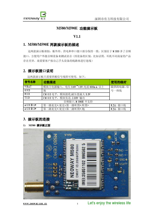
M580/M590E 功能演示板V1.11. M580/M590E 两款演示板的描述这两款演示板相似:板外形、供电和串口接口部分保持一致,区别在于M580多了音频接口,方便用户外接音频设备来测试语音(因设备的区别,比如话筒、耳机不同商家的产品存在差异,故需要客户按自己手头设备的线路来进行连线)2. 演示板接口说明这两款演示板只需要四根信号线即可使用,如下: 信号名称 功能描述使用的线材VBAT 模块主电源输入,电压3.6V~4.5V,电流600mA 以上 GND 地RXD CMOS 电平,模块接收,耐压值最大3.3V TXD CMOS 电平,模块发送, 2.85V 输出提供的电源、信号一体线音频接口, M590E 不支持AUDIO1# 第一路麦克+/麦克-,第一路听筒+/听筒- RJ11 接口线 AUDIO2# 第二路麦克+/麦克-,第二路听筒+/地RJ11 接口线3. 演示板的连接1) M580 演示板正面2)M580 演示板的背面电源和串口的输入接头3)有可能用到的连接线RJ11音频连接线:你可以通过RJ11连接线将你的电话听筒与M580演示板相连接(第一路或者第二路音频)。
一般的情况,音频连接线的绿色和红色接听筒的的麦克风(麦克正负极根据设备的不同有可能需要调整才能有声音),黄色和黑色接听筒的喇叭,无极性。
这里注意:麦克是有极性要求的,正负不能反向,否则麦克无法发声。
电源和串口连接线:绿色:模块发送数据(TXD),输出, 2.85V CMOS电平黄色:模块接收数据(RXD),输入,CMOS电平,最大能承受3.3V电压黑色:主地红色:VBATT,主电源输入,3.6~4.5V,推荐3.8V4)电源和串口开发板5)典型的连接方法,通过电脑USB接口可在电脑上进行产品调试6)与另一款开发板的连接,通过串口与电脑相连接可以将演示板的四根连接线飞到开发板的对应管脚上,用开发板进行测试4.可提供的物料清单1)M580带模块和不带模块的演示板2)M590E带模块和不带模块的演示板3)M5x0 电源板4)电源和串口连接线5)RJ11音频连接线(此项仅限于M580模块)。
TVB590 安装与简易使用手册6[1].9.7
![TVB590 安装与简易使用手册6[1].9.7](https://img.taocdn.com/s3/m/5d92e802b52acfc789ebc95d.png)
2 硬件安装
1) 2) 3) 4) 5) 6) 7) 8)
在安装前,触摸个人电脑有接地的部分,以保护 PCI 板免受静电破坏。 关闭计算机。 拔掉电脑的电源线。 打开机箱。 装配托架和电缆(仅对 TVB390 V3.O,V3.1) 。 将 PCI 卡插到电脑的 PCI 插槽上。 用螺丝将 PCI 卡固定到电脑的机箱上。 整理好机箱,插好电源线,重启电脑。
:输出码率的选项键,该选项中的设置效果和窗口 3 一样。
:射频/中频输出的选项键。其中有 RF LEVEL 选项和 C/N 选 项,RF 和 IF 选项的设置效果和窗口 6 一样。
深圳市纽拉特科技有限公司@2009
9
TVB 590/595 安装与简易使用手册
:调制方式各参数设置的选项键。ADAPTOR:信号源选择项; TYPE:调制制式选择项;BANDWIDTH:带宽选择项,有 5MHz,6MHz,7MHz,8MHz 等选项;CONSTELLATION:调制星座图选择项;CODE RATE:内纠错码选择项; TX MODE:载波选择项,有 2K,4K,8K 三个选项;GUARD INTERVAL:保护间 隔选择项,有 1/4,1/8,1/16,1/32 等选择项。
5
TVB 590/595 安装与简易使用手册
4.2 点击“Next”继续。
4.3 点击“Next”继续。
4.4 安装完成。
深圳市纽拉特科技有限公司@2009
6
TVB 590/595 安装与简易使用手册
5 操作界面简介
5.1 许可认证 当用户打开 TPG0590 播放软件时, 若出现以下图片信息时, 具体原因可参考该软件安装 目录下的日志文件 TSPHLD.LOG,表示没有插好信号源,需重新将信号源插好。
罗技M590无线鼠标使用手册说明书

ContentsIntroduction (2)Safety and General Information (2)Product Inspection (3)Getting Started (4)Battery Information (5)Assembly and Disassembly (6)Attaching the Battery (6)Removing the Battery (6)Attaching and Removing the Belt Clip (7)General Radio Operations (7)Programmable Auxiliary Functions (8)Optional Accessory (8)IntroductionThank you for your purchase of the HYT TC-610 radio - the choice for professionals. TC-610 is a professional radio that with exquisite and ergonomic design, which bring user a fine operation feel. The TC-610 is customized for noisy environments such as construction sites because all TC-610 radios are approved to dust & water protection Class IP66 and endowed with large speaker.This easy-to-use radio will deliver you secure, instant and reliable communications at peak efficiency. Please read this manual carefully before use. The information presented herein will help you to derive maximum performance from your radio.MODELS COVERED IN THIS MANUALTC-610 VHF Two-way RadioTC-610 UHF Two-way RadioSafety and General InformationThe following general safety precautions as would normally apply, which should be observed during all phases of operation, service and repair of this equipment.Turn off your radio prior to entering any area with a potentially explosive atmosphere.Do not charge your battery in a potentially explosive atmosphere.Do not use any portable radio that has a damaged antenna. If a damaged antenna comes into contact with your skin, a minor burn can result.This equipment should be serviced by qualified technicians only.T o avoid possible interference with blasting operations, turn off your radio when you are near electrical blasting caps. In a blasting area or in areas such as hospital siteposted “Turn off two-way radio”; when taking an airplane, please obey the “turn off two-way radio” instruction of aircrew staff as well.For vehicles with an air bag, do not place a radio in the area over an air bag or in the air bag deployment area. Air bags inflate with great force. If a radio is placed in the airbag deployment area and the air bag inflates, the radio may be propelled with greatforce and cause serious injury to occupants of the vehicle.Do not expose the radio to direct sunlight over a long time, nor place it close to heating source.When using your radio, hold the radio in a vertical position with the microphone 3 to 4 centimeters away from your lips.If you wear a radio on your body when transmitting, ensure the radio and its antenna are at least 2.5cm away from your body.Product InspectionBefore unpacking the TC-610 portable radio, please inspect the packaging for signs of damage and report any damage to your dealer.Upon unpacking of the TC-610 portable radio, please ensure that all items shipped were received, report any missing or damaged items to your dealer.Getting Started* PTT (Push-to-Talk) KeyPress and hold down the PTT key to transmit, release it to receive.*SK1 (Side Key 1)Side Key 1 is the programmable key that can be assigned with long press function and short press function by your dealer.*SK2 (Side Key 2)Side Key 2 is the programmable key that can be assigned with long press function and short press function by your dealer.Battery InformationInitial UseNew batteries are shipped uncharged from the factory. Charge a new battery for 5 hours before initial use, and this is true to Ni-Cd, Ni-MH and Li-Ion batteries charged with slow or rapid rate charger.Applicable Battery PacksT o reduce the risk of injury, charge only the battery specified by the manufacturer. Other batteries may burst, causing bodily injury and damage.Caution:1.T o avoid risk of personal injury, do not dispose of batteries in a fire!2.Dispose of batteries according to local regulations. Do not dispose as household waste.3.Never attempt to disassemble the battery.Battery Tips1.When charging your battery, keep it at a temperature among 5 ~ 40 to ensure a fullcharge. Temperature out of the limit will significantly reduce battery life.2.When charging a battery attached to a radio, turn the radio off to ensure a full charge.3.Do not cut off the power supply or remove the battery when charging a battery.4.Never charge a battery that is wet. Please dry it with soft cloth prior to charge.5.The battery will eventually wear out. When the operating time (talk-time and standby time)is noticeably shorter than normal, it is time to buy a new battery.To Prolong Battery Life1.Battery performance will be greatly decreased at a temperature below -20 . A sparebattery is necessary in cold weather. The cold battery unable to work in this situation may work under room temperature, so keep it for later use.2.The dust on the battery contact may cause the battery cannot work or charge. Please useclean dry cloth to wipe it before attaching the battery to the radio.Battery Storage1.Fully charge a battery before you store it for a long time, to avoid battery damage due toover-discharge.2.Recharge a battery after 3 months’ storage, to avoid reducing battery capacity due to over-discharge.3.When storing your battery, keep it in a cool, dry place under room temperature. Charging the BatteryWhen the battery level is very low, please recharge the battery.Use only the charger specified by the manufacturer. The charger’s LED indicates the charging progress.Assembly and DisassemblyAttaching the BatteryHold the battery and make it close to the top of aluminum chassis, and then lightly press the bottom of the battery until a click is heard. See figure 1 and figure 2.Figure 1Figure 2Removing the BatteryPlease turn off the radio first. Then hold the top of radio unit and press belt clip to make its tilted. Lift the battery latch in the direction of the arrow. See figure 3.Figure 3Attaching and Removing the Belt ClipLoose the screw of belt clip from the main unit, fasten the belt clip to the main unit, clockwise screw down the belt clip (See figure 4 below). Loosen the screw to remove the belt clip (See figure 5 below).Figure 4 Figure 5General Radio Operations1.Turn the Radio on-off / Volume Control knob clockwise/counter-clockwise to turn on/off theradio, then radio sounds an alert tone.2.Turn the Volume Control Knob clockwise/counter-clockwise to increase/decrease thevolume.3.Turn the Channel Selector Knob to select a channel.4.Press and hold down PTT to transmit.5.Release the PTT key to receiveProgrammable Auxiliary FunctionsYour dealer may program the TK, SK1, SK2 (long or short press) keys with one of the following auxiliary functions respectively.NonePower AdjustBattery Power IndicatorSquelch OffSquelch Off MomentaryMonitorMonitor MomentaryScanVOXOptional AccessoryMulti-unit Rapid-rate Chargerdifferent countries and areas) Receive-only Earpiece (forTube EAM12EHM15D-earset with Boom MicrophoneECM12Heavy Duty, Behind-the-Head,Noise-Canceling & VOX Headset(with screw) ECM14Programming Cable (USB port)。
PI5USB30216CXUA 用户手册说明书
ORIGINATE DATEEDIT DATE PAGE 1545 Barber Lane, Milpitas, CA 95035 U.S.A.PI5USB30216CXUA Demo Board Rev.B User ManualMeasurement by: NA Report by: Lee, JustinTable of Contents1 Introduction ..................................................................................................................................2 2 Overview ....................................................................................................................................... 23 Quick Start ....................................................................................................................................4 3.1 Source(DFP) Mode ................................................................................................................... 4 3.2 Battery-powered Sink(UFP) Mode ...........................................................................................5 3.3 Bus-powered Sink(UFP) Mode ................................................................................................6 3.4 Try.SNK DRP Mode ..................................................................................................................7 4 Circuit Description ....................................................................................................................... 9 4.1 DIP Switch Setting .................................................................................................................... 9 4.2 Mode Selection, I2C Address and I2C Bus ............................................................................ 9 4.3 VBUS Power Supply ................................................................................................................. 9 4.4 Power ...................................................................................................................................... 10 4.5 Disable/Low Power State ....................................................................................................... 10 5 Appendix A: Demo Board Schematic....................................................................................... 12 6Appendix B: Demo Board Picture (13)ORIGINATE DATEEDIT DATE PAGE 1545 Barber Lane, Milpitas, CA 95035 U.S.A.1 IntroductionPI5USB30216C provides a cost-effective solution for USB 2.0 Type-C connector applications. PI5USB30216C detects the plug-in orientation of the cable at a Type-C connector. It supports host mode, device mode and dual role mode ports with automatic configuration based on the voltage levels detected on CC pins. It is a fully-integrated solution with ultra-low power dissipation. PI5USB30216C enters power-saving mode when ENB pin is pulled up to VDD through an internal resistor.PI5USB30216C supports both pin and I2C control base on ADDR pin setting. It allows the system choose between pin control and I2C control mode. In pin control mode, the PORT input pin determines the port setting in which host, device or dual-role port can be selected. In host mode, the system can monitor ID pin to know the connector status while default current mode is set. Systems running in device mode can monitor system VBUS for connector status as well as OUT1 and OUT2 pins for host’s charging profile capability. Enabling I2C control mode allows higher flexibility for port control and communications through registers read/write in PI5USB30216C. There is also flexibility to support Default, 1.5A and 3A current modes. An interrupt signal for indicating changes with the I2C registers is sent to the master to notify the system any change in the Type-C connector while in parallel the system can still monitor ID pin.This user manual describes the components and the usage of PI5USB30216C Demo Board Rev.B.2 OverviewFigure 1 is the block diagram of Diodes PI5USB30216C demo board and figure 2 shows the demo board layout. A USB-C cable can be connected between the USB-C receptacle connector (J1) on PI5USB30216C demo board and another USB-C device. A USB-C to USB-A cable can be connected between J1 and a USB host, such as PC. A USB-C to USB-A receptacle adapter can be connected between J1 and a USB device, such as USB flash drive. One USB3 micro-AB receptacle (J2) is used to connect mobile phones/notebook/tablet/PC to transmit USB2 data to/from J1.Slide switch at reference SW1 is used to set control mode (GPIO/I2C) and operating mode (Source/Sink/DRP) of PI5USB30216C and LED indicator to SDA/SCL/INTB/ID pins of PI5USB30216C. The processor can connect to SDA/SCL/INTB/ID pins through Test Header J3.+5V can be employed to the demo board via 5VPW header pin or mini-B receptacle (J4).VBUS of Type-C connector can be source from on-board VBUS switch via JP1.ORIGINATE DATEEDIT DATE PAGE 1545 Barber Lane, Milpitas, CA 95035 U.S.A.Figure 1: Simplified Block Diagram of PI5USB30216C Demo Board Rev.BFigure 2: Layout of PI5USB30216C Demo Board Rev.BORIGINATE DATEEDIT DATE PAGE 1545 Barber Lane, Milpitas, CA 95035 U.S.A.3 Quick StartThis section provides different configuration examples to start-up PI5USB30216C demo board rev.B in Source, Sink or DRP mode. 3.1 Source (DFP) ModeTo start-up the PI5USB30216C demo board rev.B in pin control DFP mode, complete the following steps: 1. Configure pin headers and DIP switches SW1 as shown in Table 1.2. Power-up PI5USB30216C demo board by connecting J2 to a USB host using Type-A to micro-B cable. D2 should lightup indicating the board has power.3. Connect PI5USB30216C demo board to a Type-C Sink(UFP) using a Type-C cable. D6 should light up indicating IDpin is pulled low and 5V VBUS is provided by the demo board. .Figure 3: PI5USB30216C Demo Board DFP mode illustration.Header pin/Switch Pin name/ Function Setting SW1.1 ENB = LON SW1.2 SCL/OUT2 LED indicator OFF SW1.3 SDA/OUT1 LED indicatorOFF SW1.4 ADDROFF SW1.5 INTB/OUT3 LED indicatorON SW1.6 ID LED indicator ON SW1.7 PORT = H ON SW1.8 PORT = LOFF JP1 Connect output of VBUS switch to VBUSCON JP3 Demo board power by VBUSA ON JP5 Connect VBUSC to VBUSA OFF JP9 Connect 5VPW to VDD OFF JP10Enable 3.3V VDDONTable 1: PI5USB30216C Demo Board Rev.B DFP mode configuration.ORIGINATE DATEEDIT DATE PAGE 1545 Barber Lane, Milpitas, CA 95035 U.S.A.3.2 Battery-powered Sink (UFP) ModeTo start-up the PI5USB30216C demo board rev.B in pin control UFP mode, complete the following steps: 1. Configure pin headers and DIP switches SW1 as shown in Table 2. 2. Connect J2 to a USB device using micro-A to Type-A receptacle.3. Power up PI5UB30216C demo board by connecting J4 to a USB host using Type-A to mini-B cable (or connect +5V to5VPW pin header). D2 should light up indicating the board has power.4. Connect PI5USB30216C demo board to a Type-C Source(DFP) using a Type-C cable. 5V VBUS should be providedby the Type-C Host/Source/DFP. D3 and D4 might light up depends on the DFP’s Type-C current mode setting.Figure 4: PI5USB30216C Demo Board battery-powered UFP mode illustration.Header pin/Switch Pin name/ Function Setting SW1.1 ENB = LON SW1.2 SCL/OUT2 LED indicator ON SW1.3 SDA/OUT1 LED indicatorON SW1.4 ADDROFF SW1.5 INTB/OUT3 LED indicatorOFF SW1.6 ID LED indicator OFF SW1.7 PORT = H OFF SW1.8 PORT = LON JP1 Enable On-board VBUS switch OFF JP3 Demo board power by VBUSA OFF JP5 Connect VBUSC to VBUSA ON JP9 Connect 5VPW to VDD OFF JP10 Enable 3.3V VDDONTable 2: PI5USB30216C Demo Board Rev.B battery-powered UFP mode configuration.ORIGINATE DATEEDIT DATE PAGE 1545 Barber Lane, Milpitas, CA 95035 U.S.A.3.3 Bus-powered Sink(UFP) ModeTo start-up the PI5USB30216C demo board rev.B in pin control VBUS-powered UFP mode, complete the following steps: 1. Configure pin headers and DIP switches SW1 as shown in Table 3. 2. Connect J2 to a USB device using micro-A to Type-A receptacle.3. Connect PI5USB30216C demo board to a Type-C Source(DFP) using a Type-C cable. 5V VBUS should be providedby the Type-C Host/Source/DFP. D2, D3 and D4 might light up depends on the DFP’s Type-C current mode setting.Figure 5: PI5USB30216C Demo Board VBUS-powered UFP mode illustration.Header pin/ Switch Pin name/ Function Setting SW1.1 ENB = LON SW1.2 SCL/OUT2 LED indicator ON SW1.3 SDA/OUT1 LED indicatorON SW1.4 ADDROFF SW1.5 INTB/OUT3 LED indicatorOFF SW1.6 ID LED indicator OFF SW1.7 PORT = H OFF SW1.8 PORT = LON JP1 Enable On-board VBUS switch OFF JP3 Demo board power by VBUSA ON JP5 Connect VBUSC to VBUSA ON JP9 Connect 5VPW to VDD OFF JP10 Enable 3.3V VDDONTable 3: PI5USB30216C Demo Board Rev.B VBUS-powered UFP mode configuration.ORIGINATE DATEEDIT DATE PAGE 1545 Barber Lane, Milpitas, CA 95035 U.S.A.3.4 Try.SNK DRP ModeTo start-up the PI5USB30216C demo board rev.B in pin control Try.SNK DRP mode, complete the following steps: 1. Configure pin headers and DIP switches SW1 as shown in Table 3 in the next page.2. Power up PI5UB30216C demo board by connecting J4 to a USB host using Type-A to mini-B cable. D2 should light upindicating the board has power.3. Connect PI5USB30216C demo board to a Type-C Sink(UFP) using a Type-C cable. D6 should light up indicating IDpin is pulled low and 5V VBUS is provided by the demo board.4. Connect PI5USB30216C demo board to a Type-C Source(DFP) using a Type-C cable. 5V VBUS should be providedby the Type-C Host/Source/DFP. D3 and D4 might light up depends on the DFP’s Type-C current mode setting5. Connect PI5USB30216C demo board to a Type-C DRP using a Type-C cable. PI5USB30216C should connect asSink/UFP due to Try.SNK feature. 5V VBUS should be provided by the port partner. D3 and D4 might light up depends on port partner’s Type-C current mode setting.6. Connect PI5USB30216C demo board to a Type-C Try.SNK DRP using a Type-C cable. PI5USB30216C may result ineither DFP or UFP mode. The result is random.a. When connect as a Source/DFP/Host, D6 should light up indicating ID pin is pulled low and 5V VBUS is providedby the demo board.b. When connect as a Sink/UFP/Device. 5V VBUS should be provided by the port partner. D3 and D4 might light updepends on port partner’s Type-C current mode setting.Figure 6: PI5USB30216C Demo Board Try.SNK DRP mode illustration.ORIGINATE DATE EDIT DATE PAGE 1545 Barber Lane, Milpitas, CA 95035 U.S.A.Header pin/ Switch Pin name/ Function Setting SW1.1 ENB = LON SW1.2 SCL/OUT2 LED indicator ON SW1.3 SDA/OUT1 LED indicatorON SW1.4 ADDROFF SW1.5 INTB/OUT3 LED indicatorON SW1.6 ID LED indicator ON SW1.7 PORT = H OFF SW1.8 PORT = LOFF JP1 Enable On-board VBUS switch ON JP3 Demo board power by VBUSA OFF JP5 Connect VBUSC to VBUSA OFF JP9 Connect 5VPW to VDD OFF JP10Enable 3.3V VDDONTable 4: PI5USB30216C Demo Board Rev.B Try.SNK DRP mode (pin control mode) configuration.ORIGINATE DATEEDIT DATE PAGE 1545 Barber Lane, Milpitas, CA 95035 U.S.A.4 Circuit Description4.1 DIP Switch SettingThe DIP switch (SW1) is used to configure PI5USB30216C in different mode.Header pin/ Switch Pin name/ FunctionDescription SW1.1 ENBENB = Low if SW1.1 is ON.ENB = High if SW1.1 is OFF.SW1.2 SCL/OUT2 LED indicator For pin control mode:OUT2 is connected to LED if SW1.2 is ONFor I2C mode:SW1.2 shall be OFF.SW1.3 SDA/OUT1 LED indicator For pin control mode:OUT1 is connected to LED if SW1.3 is ONFor I2C mode:SW1.2 shall be OFF.SW1.4 ADDR For pin control mode: SW1.4 is OFF.For I2C mode: SW1.4 is ON. I2C mode; 0x1D (Default)I2C mode; 0x3D (Remove R30 and solder R28)SW1.5 INTB/OUT3 LED indicator OUT3 is connected to LED if SW1.5 is ON SW1.6 ID LED indicator ID is connected to LED if SW1.6 is ON SW1.7 PORT = H PORT = Open if SW1.7 is OFFPORT = High if SW1.7 is ONSW1.8 PORT = L PORT = Open if SW1.8 is OFFPORT = Low if SW1.8 is ONTable 5: DIP Switch SW1 settings4.2 Mode Selection, I2C Address and I2C BusPI5USB30216C can be controlled via either GPIO or I2C mode. The control mode and I2C address is configured via ADDR pin (refer to section 4.1). Pins 8 and 7 of PI5USB30216C are used for transmitting I2C SCL and SDA, respectively. External pull-ups may be required for SCL(OUT2) and SDA(OUT1) pins when reading/writing I2C. Alternatively, pull-ups for SCL(OUT2) and SDA(OUT1) can be enabled by short pins 1-2 and 3-4 of JP13.4.3 VBUS Power SupplyThe system should drive 5V to VBUS of USB-C receptacle connector (J1) when a sink/UFP is attached. If an external VBUS switch not available, a discrete VBUS switch DPS1113 is assembled on EVB, which is controlled by ID pin of PI5USB30216C. This switch will turn on and drive VBUS, when a sink/UFP is attached. To use the on-board VBUS switch, please shorts JP1.For detailed DPS1113 function and setting, please refer to DPS1113 datasheet.ORIGINATE DATEEDIT DATE PAGE1545 Barber Lane, Milpitas, CA 95035 U.S.A.Figure 7: VBUS switch of PI5USB30216C Demo Board Rev.B4.4 PowerIn DRP and battery-powered UFP mode, the demo board can be powered by +5V VBUS through mini-B connector J4 or by +5V through pin header 5VPW.In DFP mode, the system/host can provide +5V through the USB micro-AB connector J2 to power up the board via JP3.Figure 8: Power Supply option of PI5USB30216C Demo Board Rev.B4.5 Disable/Low Power StatePI5USB30216C can be disabled by setting ENB pin to a high voltage level. Please refer section 4.1.ORIGINATE DATEEDIT DATE PAGE 1545 Barber Lane, Milpitas, CA 95035 U.S.A.References(1) Universal Serial Bus Type-C Cable and Connector Specification Version 1.1, April 3, 2015ORIGINATE DATEEDIT DATE PAGE1545 Barber Lane, Milpitas, CA 95035 U.S.A.5 Appendix A: Demo Board SchematicFor clearer view of schematic diagram, please click the PDF file icon on the right. PI5USB30216CXU A_TYPE C_EVB_REVBORIGINATE DATEEDIT DATE PAGE1545 Barber Lane, Milpitas, CA 95035 U.S.A.6 Appendix B: Demo Board PictureORIGINATE DATEEDIT DATE PAGE 1545 Barber Lane, Milpitas, CA 95035 U.S.A.Revision History Revision Date DescriptionEdit by Verify by1.0 16 May, 2017 Initial Justin Lee。
欧陆590简易说明

590+使用说明本说明涉及启动590+的基本步骤。
驱动器启动应由相关资质电气工程师完成。
关于安装、安全使用性能及应用细节请参阅产品说明书。
驱动安装符合电器安装规则,所有带电部分应覆盖,以防电击和突然启动对人身造成伤害。
驱动器安装在特定位置,相关安装步骤依次进行。
请确保驱动器有足够通风空间,正常使用状态环境温度不超过摄氏35度。
通过拉动底部端盖连接控制端子,打开上部端盖连接电源端子。
电机励磁D3(F+),D4(F-)三相接触器电源D5(L),D6(N)辅助电源D7(N),D8(L)电机热敏电阻THERM+,THERM-电枢电压A+,A-三相电源L1,L2,L3接地速度设定,电压A1低电位,B3高电位,A4电位器中间点。
或连接外部电压A1(-)。
A4(+)之间。
短接A6,B3程序停机B8,C9惯性滑行B9,C9无外部跳闸保护短接C1,C2允许输入短接C5,C9启动短接C3,C9点动短接C4,C9传动正常继电器B6,C1电枢电压反馈不需反馈卡有四个反馈接卡,模拟转速,编码器,聚丙烯微转速仪、玻璃微转速仪。
选择正确反馈形卡,安装在反馈头上模拟反馈设置拨码开关。
DC模拟G3,G4,AC模拟G1,G2编码器E1=0,E2=+,E3,E4=A,-A,E5,E6=B,-B微转速C1=0V,C9=24V,F1=光纤DIGITAL DC DRIVEDC 4Q 270AM DC 4Q 270AMENU LEVEL按M键进入主菜单M MENU LEVELDIAGNOSTICS(诊断)按M键进入主菜单,在诊断位置^ MENU LEVELCONFIGURE DRIVE向上箭头,到装载驱动菜单M CONFIGURE DRIVECONFIGUREEANBLE按M和向上箭头,到允许装载驱动,在装载模式7只LED 闪亮。
按ENOM MOTOR VOLTS用上升下降箭头,输入额定电压ARMATURE CURRENT输入电枢电流FIELD CURRENT励磁电流FLD CTRL MODE转换电流电压模式FLD VOLTS RATIO电压模式下比率=(励磁电压/电源电压)*100%MAIN CURR LIMIT输入限止电流,通常为100%AUTOTUNE关闭,设置完成自动调谐SPEED FBK SELECT选择电压反馈/测速反馈/编码器反馈ENCODER LINES输入编码器每转脉冲ENCODER RPM输入最大速度,ENCODER SIGN改变编码器极性SPD INT TIME速度环增速SPD PROP GAIN速度环比例增速装载设置从允许/禁止,驱动将显示分类菜单界面/参数在菜单级/参数储存,按M和上下箭头保存设置。
一体板USB编程器使用说明
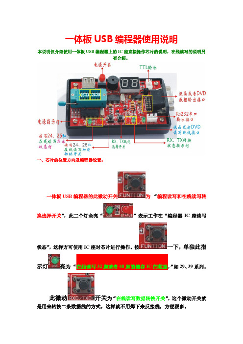
一体板USB编程器使用说明本说明仅介绍使用一体板USB编程器上的IC座直接操作芯片的说明,在线读写的说明另有介绍。
一、芯片的位置方向及编程器设置:一体板USB编程器的此微动开关为“编程读写和在线读写转换选择开关”,此二个灯全亮“”表示工作在“编程器IC座读写状态”,这样方可使用IC座对芯片进行操作。
按一下,单独此指示灯亮为“在线读写32脚或者48脚的储存IC的数据,”如29、39系列。
此微动开关为“在线读写数据转换开关”,这个微动开关就是用来转换二条数据线的方式,这样就不用焊下来反接线,方便很多。
二、应用程序的使用:在这之前要先安装了一体板USB编程器的驱动后方可正式常用,驱动的安装请参看“驱动安装说明”。
下面介绍编程器软件的用法:UCB口24-25系列编程器软件:在使用此软件的时候,请先插入编程器到电脑,是状态指示灯为红色,并装上芯片到IC座上。
否则可能会引起程序假死现象,请注意。
芯片选择区域:用于选择您想操作的芯片型号,对于24系列的芯片,直接鼠标点选相应的型号,对于25系列的芯片,选择该芯片的存储字节的数量即可,例如25T80芯片请选择“1M字节”。
状态指示:底部左侧的文字用于显示当前是否已经插入编程器,但不检测是否插入芯片。
代码编辑区:中间的白色矩形区域是用于显示打开的文件内容或从存储器芯片中读出的数据内容,为十六进制代码。
打开按钮:打开存储器数据文件并显示在中间的编辑区内,准备写入芯片。
一般为BIN 扩展名,也有特例的。
保存按钮:将编辑区内的内容保存到文件中,以备后用。
多数用于将芯片中的数据读出后保存起来。
读取按钮:将芯片中的内容读出并显示在编辑器内,以备编辑或保存成文件,注意实际芯片与界面选择的芯片要对应。
写入按钮:将编辑区内的内容写入芯片中,注意实际芯片与界面选择的芯片要对应。
写入完成会有提示。
如果编辑区中的内容长度小于所选择的芯片,只写入编辑区内容的长度为止,芯片从0地址开始写。
usb-fpga-开发板使用手册说明书

USB FPGA 开发板使用手册一、开发板简介USB FPGA开发板在设计上充分考虑到实际应用的需要,增强了FPGA扩展能力和处理能力,使之能更好的适合更复杂的应用。
板上扩展了两容量64M字节总线独立的SDRAM存储器,使板卡能更适合于数据计算和数据传输缓存,同时采用CYPRESS公司的USB2.0高速传输芯片,保证了板卡的数据传输能力。
板卡扩展了FPGA的84个端口,足以保证实际的外部连接需要。
同时增加了一片MAX3232电平转换芯片,使之与FPGA连接,可以设计FPGA的串口数据传输通信。
板卡同时支持USB供电和外部供电方式,板载的3.3V电源芯片足够提供3A 的电流,可以为外部板卡提供电源。
板卡的提供大量的实际有价值的程序,并且我们将不断的升级和开发使用与这个板卡的应用程序。
板卡上大容量的SDRAM足以在FPGA上运行NIOSII操作系统。
考虑到FPGA的管脚数量有限,而且已经给FPGA配置了EPSC4,因此未扩展FLASH 存储器。
我们为这个板卡开辟专门的技术交流网页,应用程序将在上面更新。
二、板上主要芯片:USB芯片:CY7C68013A‐56FGPA芯片:EP2C8Q208C8SDRAM芯片两片:MT48LC16M16A2FPGA配置芯片:EPCS4串口收发芯片:MAX3232ESEEEPROM芯片: 24LC643.3V LDO:LM1085‐3.31.2V LDO:LM1117‐1.250MHZ有源晶振三、电路板硬件说明1. 电路板实物图1:FPGA的AS模式下载接口2:FPGA的JTAG模式下载接口3:4个与FPGA管脚相连的LED4:FPGA的配置程序重新加载按键5:MT48LC16M16A2 SDRAM存储器6:CY7C68013A程序存储器EEPROM 24LC647:CY7C68013A芯片8:FPGA EP2C8Q2089: 串口电平转换芯片MAX323210:MT48LC16M16A2 SDRAM存储器11:FPGA 的外部有源时钟12:CY7C68013A 的复位按键13:USB接口14:外部5V电源输入,提供给板子电源(可以不接,由USB接口提供电源输入) 2. 电路板的管脚分配详细的管教分配请看文档 《USBFPGA第四版硬件配置手册.pdf》。
柯达M590数码相机
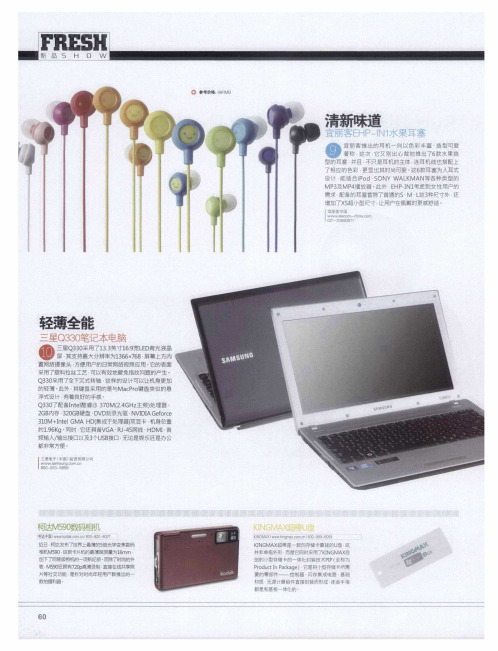
三基电子 ( 中国) 投资有阳公司
嚣 一 器
柯达M5O - 9数6相机 5
柯选中国1 w o a r n BO 8 0 6 2 w wkd k on IO 一 2 ・ 0 7 c c
一 C 要采 P0 创闵 并是 K8 都储 材装 I梁 r用 N确 是 质 o 的 非f G一 d M 和 霉 小 单 u A 无 c X 指 基 部 型 t I v 源 存 外 a 板 件 × n  ̄ 计 w 形 超 一 储 — P k 算 a 棒 i 体 卡 n c g 组 而 是 m f 的 b a 控 件 一 x 制 e 它 直 o 款 体 1 m 器 同 接 , { 向 c 它 n 匕 时 封 、 存 I
浮式设计 - 有着良好的手戚
Q 3 了配备Itl 330 24 H 主频) 3o ne 酷睿i 7 M(.G z 处理器 、
2 内存 3 O 硬 盘 、 D ̄ 录 光驱 、 DA fre GB 2 G8 DV U NⅥ I Geoc
30 ItI MA H ( 1M+ne G D集成于妪理器) 双显卡 . 机身总重
置网络摄像头 - 方便用户的日常网络视频应用 ・ 它的表面
采用 了塑 料拉 丝 工艺 ・ 以有 效地 避 免指 纹 问题 的产 生 。 可
Q 3 采用了 30 全下沉式转轴 - 这样的设计可以让机身更加
的 轻薄 。 此外 ・ 键盘 采 用 的是 与 Ma Po键 盘类 似 的 悬 其 cr
线性技术590B快速入门指南说明书
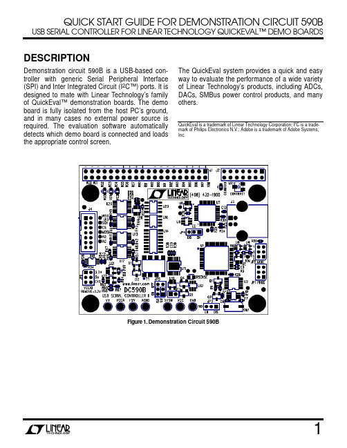
QUICK START GUIDE FOR DEMONSTRATION CIRCUIT 590B USB SERIAL CONTROLLER FOR LINEAR TECHNOLOGY QUICKEV AL™ DEMO BOARDSDESCRIPTIONDemonstration circuit 590B is a USB-based con-troller with generic Serial Peripheral Interface (SPI) and Inter Integrated Circuit (I2C™) ports. It is designed to mate with Linear Technology’s family of QuickEval™ demonstration boards. The demo board is fully isolated from the host PC’s ground, and in many cases no external power source is required. The evaluation software automatically detects which demo board is connected and loads the appropriate control screen. The QuickEval system provides a quick and easy way to evaluate the performance of a wide variety of Linear Technology’s products, including ADCs, DACs, SMBus power control products, and many others.QuickEval is a trademark of Linear Technology Corporation; I2C is a trade-mark of Philips Electronics N.V.; Adobe is a trademark of Adobe Systems,Inc.Figure 1. Demonstration Circuit 590BFigure 2. Basic ConnectionsSelect Isolated Supply Voltage (2.7V, 3.3V, 5.0V, or ExternalQUICK START PROCEDUREFor proper equipment setup, follow the procedure below:1. Do NOT plug in DC590B before running the in-stallation program.2. Download the QuickEval installation program from/software/.3. Run the QuickEval installation program and fol-low the on-screen instructions. NOTE: The QuickEval demo software requires a PC that is running Windows 98 (or later), and has an available USB port.4. Connect the demonstration circuit to be evalu-ated to DC590B using the supplied 14-conductor ribbon cable. The demo software de-tects the circuit and starts the appropriate con-trol screen.Each demonstration board also comes with a Quick Start guide similar to this one. For usage details relevant to a particular circuit refer to its Quick Start Guide.SOFTWARE TOOLSThe QuickEval Demo software includes tools for automatic software updates and for quickly retriev-ing relevant documentation from the World Wide Web.NOTE: Adobe Acrobat reader is required to view the documents and is available at .To use the tools:•Quit the demonstration circuit software ordis-connect the USB cable so that The main controlpanel appears:To update the software (requires internetconnection):•Choose Update from the Tools menu.This automatically updates the main programand drivers for individual demo circuits.To view the Quick Start Guide (this document):•Choose Quick Start Guide from the Viewmenu.CONNECTIONS TO THE DC590BFigure 2 shows the connections to the DC590B. In most cases DC590B and the demonstration circuit under evaluation can operate from available USB power, and thus require nothing more than a USB connection to the host PC and a ribbon connect-ing DC590B to the demo circuit under evaluation. DC590B offers several other power options, de-scribed below.Isolated Supply OptionsAn LT3439 low-noise switching power supply pro-vides isolated power to the demonstration circuit under evaluation and to the isolation circuitry. This is adequate in many cases, however an external power supply is recommended to reduce the load on the host computer’s USB port or to reduce power supply noise in the circuit under test.The LT3439 switching power supply is enabled by default but may be disabled by moving jumper JP5 (ISO, to the left) to the OFF position. This al-lows the isolated side of the board and the dem-onstration circuit under evaluation to be powered separately. This is recommended when testing precision components such as high resolution ADCs and DACs. After moving JP5 ISO to the OFF position, apply a clean, regulated power sup-ply from 7v to 10V to the V+ and AGND turret posts.Isolated Digital SupplyThe signal levels on the digital interface are de-termined by the VCCA voltage. The onboard regu-lator can be set to 5V, 3.3V, 2.7V by installing JP6 in the appropriate position (remove jumper for 2.7V.) Selecting EXT shuts the regulator down, and an external supply between 2.7 and 5V must be applied to the VCCA turret post.The +5V turret is the digital supply for the isolated portion of DC590B. Do not draw current from this pointLED IndicatorsTwo LED indicators are provided. The “ISO PWR” LED is lit when either the onboard switching power supply is running or external power is ap-plied to the isolated side of the board.The “COMMAND” LED indicates that a command has been sent to the board by the host PC and is waiting to be executed. The LED may not appear to be blinking in some cases, as the duty cycle may be very short.Jumper SummarySome jumpers on the DC590 board are for future use and MUST be left in the default positions.JP1 – PROG – Microcontroller in-circuit program-ming header, do NOT install jumper, make no con-nections.JP2 – MODE – do NOT install jumper, make no connections.JP3 – Watchdog enable - do NOT install jumper, make no connections.JP4 – EE – Jumper MUST be in the EN position. JP5 – SW (right-hand side) MUST be in the ON position. ISO (left-hand side) controls the isolated supply. See Connections section.JP6 – VCCA control. See Connections section.TROUBLESHOOTING GUIDEDC590B is plugged in, but QuickEval screen still says “USB Serial Controller Not Con-nected”The most likely cause is improper instal-lation of the USB drivers, which causes Windows to recognize DC590 as an “Unknown Device.” Open the Windows Control Panel, open “System” and click the “Device manager” tab. Open the “Other Devices” item and look for USB SERIAL CONTROLLER. Select this item and click the re-move button. Unplug DC590, Re-install the QuickEval software, and follow the on-screen in-structions.Demo board software loads properly, but will not run or gives “Device Not accessible” errors.Verify that the demo board is properly powered up. This Quick Start Guide lists the basic power connections to DC590. Some demo boards may have additional requirements; refer to the demo board’s Quick Start guide for details. After connecting the demo board to DC590 with the supplied 14 pin ribbon cable, QuickEval software still displays “Evaluation Board is not Connected.”Contact Linear Technology Applications Engineering.Problem: Solution : Problem: Solution: Problem: Solution:VCC (Reworked on first run of boards.)_APPENDIX A APPENDIX A: DC590A CONNECTIONS AND SCHEMATICThis section shows the schematic and connec-tions to DC590A, which DC590B replaces. The only functional difference between DC590A and DC590B is that the digital signals on DC590B can be adjusted from 2.7 to 5V, where the DC590A is 5V only.DC590B also offers improved isolation, as all 14 conductors on the 14 pin interface header are iso-lated from the PC’s ground. Figure 3 shows how to connect an external supply to the isolated side of the controller and the board under evaluation. After disabling the switching supply by placing JP1 in the OFF position, apply 7V–9V between the GND and V+ posts. These posts are the in, out, and ground terminals of an LT1761 LDO regulator. The demonstration circuit under evaluation may draw up to 100mA from V CC.Figure 3. Connecting an external supply to the isolated side of the controllerAPPENDIX AAnother option is to supply power to the iso-lated side of the controller (see Figure 4) back through the board under evaluation. The LT1761 regulator is reverse-current pro-tected. This allows any convenient 5V ±10% regulated supply to be used. In this case, the isolation circuitry on DC590 is also powered from this source. worst-case current draw by DC590 is 50mA.Figure 4. Supplying power to the controller through the board under evaluation。
海尔电子有限公司产品说明书:HHM591T、HHM590、HHM596 HHM596C数字多功能电压

Clamp-On Digital Multimeters HHM591T Clamp-On Multimeter 1999 counts resolution AC current up to 700 A DC current up to 700 A with EL panel LCD HHM590 Clamp-On Multimeter 1999 counts resolution AC current measurement up to 700 A HHM596/HHM596C AC/DC Clamp-On Multimeter 4300 counts resolution AC current up to 700 A DC current up to 700 A Vac basic accuracy ±1.2%DC current basic accuracy ±1.5%HHM596C with °C/°F switchable Type K thermocouple HHM596C Available with °C/°F Switchable Type K thermocouple:HHM596 (No temperature measurement)HHM596C HHM591THHM591 Clamp-On Multimeter 1999 counts resolution AC current up to 700 A DC current up to 700 A HHM59U GS-Mark EN61010-1 Approval Voltage Category III 600 V, Pollution Degree IIU AC/DC Current ClampU Highly Accurate 1999, 2500, 3999, 4300 Counts ResolutionU MAX, Data Hold, PEAK, ∆ ZERO FunctionsU Model HHM592, HHM592D, HHM596, HHM596C, HHM599 with Auto-Ranging OperationU Battery Life: 200 HoursU Dimensions: 250 H x 100 W x 46 mm D (9.9 x 3.9 x 1.8")U Weight: Approx 320 g (10.8 oz)M e a s u r e s T e m p e r a t u r e All clamp-on meters come with high qualitydeisgn HHM-TL general use test lead set.HHM590HHM598T AC True-RMS Clampmeter 1999 counts resolution AC current measurement up to 700 A Basic accuracy ± 1.5%HHM599 AC/DC True-RMS Clampmeter 33⁄4 digit 3999 counts AC current up to 700 A DC current up to 700 A DC current accuracy ± 1.5%Resistance accuracy ± 0.3%HHM598 Clamp-On Multimeter 1999 counts resolution AC current measurement up to 700 A AC current basic accuracy ±1.5%HHM598C/HHM598F Multimeter 1999 counts resolution AC current measurement up to 700 A Basic accuracy ± 1.5%2 Models Available for °C or °F:HHM598CHHM598FHHM598HHM598T HHM599 Temperature models include a free 1 m (40") Type K insulated beaded wire thermocouple with subminiature connector and wire spool caddy (1 per channel).Order a Spare! Model No. SC-GG-K-30-36Thermocouple Included!All clamp-on meters come with a set of safety test leads, 9 V alkaline battery, Type K beaded wire thermocouple (temperature models only) and complete operator’s manual.M e a s u r e s T e m p e ra t u r e .Clamp-On Meters Selection GuideComes with a set of safety test leads, 9 V alkaline battery, Type K beaded wirethermocouple (temperature models only) and complete operator's manual.HHM590HHM598TAll clamp-on meters come with HHM-TL General use test lead set.High quality design.HHM596CHHM598HHM59HHM58Temperature models include a free 1 m (40") Thermocouple Included!。
M590-USB开发板使用说明
深圳市有方科技有限公司
(技术文档)
M590-USB开发板使用说明
V1.0
修订记录
版本号 更改内容 生效年月 V1.0 初始版本
M590-USB开发板使用说明
一、 开发板实物照片
本开发板适用于M590模块。
AT/数据通讯和电源都用标准的USB端口。
二、 接口说明
1.J1为开机的短路跳线,如果接通,相当与开机一直有效。
模块会上电自动开机。
2.指示灯说明:
1)D10为电源指示灯。
2)D12为运行指示灯,连接模块的LIGHT引脚,模块运行过程中按1秒的频率
闪烁,运行过程中只有这一种指示状态。
由于该开发板对外用USB口通讯,而实际上模块还是串口,开发板上有USB转串口的转换芯片,型号是PL2303HX,所以需要在PC上安装USB的驱动程序。
三、 USB驱动程序
PL2303HX驱动程序.rar。
Seiko Epson UB-B03 蓝牙接口板用户操作手册说明书

User’s ManualCopyright © 2012 Seiko Epson Corporation Printed in China Introduction The UB-B03 is an interface board on which is installed a Bluetooth ® module for EPSON TM printers.This manual provides instructions for operators to use the UB-B03 safely and correctly.This Bluetooth interface board is exclusively for EPSON TM printers with a slot dedicated for it. No devices other than EPSON TM printers can use this.The Bluetooth interface board is listed as a limited modular transmitter device because its radio elements do not have its own shielding. Therefore, when it is installed in the printer, be sure to push the board fully into the slot.Features and Functions❏Compliant with Bluetooth Version 2.1 + EDR.❏Bluetooth Power Class 2 supported.❏SPP (Serial Port Profile) supported.Precautions on DIP SwitchesDo not change settings of DIP switches on the UB-B03. See the illustration below for the position of the DIP swithes.Communication SettingsParameters for Serial CommunicationThe parameters for the UB-B03 is fixed as follows:Make the same settings to the printer.❏Transmission speed:115200 bps (bits per second)❏Data word lengh:8 bits❏Parity check:Disabled❏Handshaking:DTR/DSR412430403Pass KeyWhen connecting with the UB-B03 for the first time, a pass key may be required. In that case, input 0000 for the pass key.Standards and ApprovalsProduct Name: UB-B03Model Name: M212BThe following standard is applied only to the interface boards that are so labeled. (EMC is tested using the EPSON power supplies and TM series printers.)North America:FCC/RSS-210Europe:CE markingWARNINGYou are cautioned that changes or modifications not expressly approved by Seiko Epson Corporation could void your authority to operate the equipment.DECLARATION of CONFORMITYManufacturer:SEIKO EPSON CORPORATIONAddress:3-5, Owa 3-chome, Suwa-shi,Nagano-ken 392-8502 JAPANRepresentative:EPSON FRANCE S.A.Address:Parc Technologique Europarc 60, Rue AugustePerret 94043 Creteil Cedex FranceDeclares that the Product:Product Name:Bluetooth Interface Board for PrinterModel Name: M212BCommercial Name: UB-B03Conforms to the following Directives and NormsR&TTE: Directive 1999/5/ECEN 300 328EN 301 489-1EN 301 489-17EN 60950-1EN 62311RF ModuleThis equipment has the following wireless module.Manufacturer: Seiko Epson CorporationModel Name: M212BProduct Name:Bluetooth Interface Board for PrinterThis device complies with Part 15 of the FCC Rules. Operation is subject to the following two conditions: (1) this device may not cause harmful interference, and (2) this device must accept any interference received, including interference that may cause undesired operation.CanadaThis device conforms to IC, Low Power License-Exempt Radio Communication Devices (RSS-210). The information such as Certification No., Model Name, and Manufacturer Name are described on the surface of the module.Operation is subject to the following two conditions:(1) this device may not cause interference, and(2) this device must accept any interference, including interference that may cause undesired operation of this device.L'utilisation de ce dispositif est autorisee seulement aux conditions suivantes:(1) il ne doit pas produire de brouillage et(2) l'utilisateur du dispositif doit etre pret a accepter tout brouillage radioelectrique recu, meme si ce brouillage est susceptible de compromettre le fonctionnement du dispositif.Caution: Exposure to Radio Frequency RadiationTo comply with FCC/IC RF exposure compliance requirements, a separation distance of at least 20 cm {7.87"} must be maintained between the antenna of this device and all persons. This device must not be co-located or operating in conjunction with any other antenna or transmitter.EuropeHereby, Seiko Epson Corporation declares that this M212B is in compliance with the essential requirements and other relevant provisions of Directive 1999/5/EC.ItalyIn Italy, if used outside of own premises, general authorization is required.The UB-B03 can be usedonly in the countries listed below:Austria, Belgium, Germany, Luxembourg, Netherlands, Switzerland, France, Italy, Greece, Spain, Portugal, Denmark, Finland, Ireland, Sweden, UK, Czech Republic, Estonia, Hungary, Lithuania, Latvia, Poland, Slovenia, Slovak Republic, Norway, Bulgaria, Romania, U.S.A., and CanadaAll rights reserved. No part of this publication may be reproduced, stored in a retrieval system, or transmitted in any form or by any means, electronic, mechanical, photocopying, recording, or otherwise, without the prior written permission of Seiko Epson Corporation. No patent liability is assumed with respect to the use of the information contained herein. While every precaution has been taken in the preparation of this book, Seiko Epson Corporation assumes no responsibility for errors or omissions. Neither is any liability assumed for damages resulting from the use of the information contained herein.Neither Seiko Epson Corporation nor its affiliates shall be liable to the purchaser of this product or third parties for damages, losses, costs, or expenses incurred by purchaser or third parties as a result of: accident, misuse, or abuse of this product or unauthorized modifications, repairs, or alterations to this product, or (excluding the U.S.) failure to strictly comply with Seiko Epson Corporation’s operating and maintenance instructions.Seiko Epson Corporation shall not be liable against any damages or problems arising from the use of any options or any consumable products other than those designated as Original EPSON Products or EPSON Approved Products by Seiko Epson Corporation.EPSON is a registered trademark of Seiko Epson Corporation in Japan and other countries/regions. Notice: The contents of this manual are subject to change without notice.。
有方M580-M590待机(低功耗)模式使用说明
有无线,方精彩深圳市有方科技有限公司版权所有 第1页,共1页 有方M580/M590的待机(低功耗)模式使用说明M580/M590在通话、数据过程中的工作电流约为220mA ,在非连接状态下的工作电流约为25mA ,在待机(低功耗)模式下的平均工作电流约为2.5~2.8mA 。
在待机模式下,模块会及时响应系统侧的来电、短信和数据业务。
在本端,外部CPU 也可以通过硬件IO (DTR )来控制模块退出休眠模式。
控制模块进入待机模式的基本流程:1、 保持模块的DTR 输入为高电平,通过AT 指令将模块设置为允许进入休眠模式,参考指令:at+enpwrsave 。
2、 将模块的DTR 输入置低,硬件控制模块进入低功耗状态。
通常模块会在2秒左右进入待机。
在待机模式下,模块的串口是关闭的,没有响应。
运行灯也会停止闪烁。
模块只有在空闲时才会进入待机模式,如果有数据交互未结束,不会进入待机。
3、 如果本端有数据或者呼叫等主叫业务,可以将DTR 置高,模块立即退出待机模式,进入正常模式,串口打开响应AT 指令。
在主叫业务处理完毕后,外部CPU 再将DTR 置低,模块进入待机模式。
4、 在待机状态下,如果模块有被叫业务,比如来电、来短信、服务器来的数据,模块会立刻退出待机模式,并通过串口输出来电信息,外部CPU 在检测到串口信息后,建议先将DTR 置高,再处理来电、数据等。
待处理完毕后,将DTR 置低,使模块进入待机模式。
如果来电时,DTR 没有置高,且串口没有信息,则模块会在2~30秒左右自动进入待机模式。
在语音来电时,在振铃过程中,模块的RING 脚会持续输出周期的6秒,低脉冲宽度为30ms 的周期信号。
在短信来电时,在使用AT+CNMI 设置短信提醒后,在收到短信时,模块的RING 脚会输出一个25ms 低脉冲。
在数据业务来电时,RING 信号没有变化,保持为高电平。
Neo_M590E模块硬件设计指南 V1.1
Neo_M590E 硬件设计指南 Version 1.1 深圳市有方科技有限公司 有无线,方精彩 Let's enjoy the wireless life! Neo_M590E 硬件设计指南V1.1 版权声明 Copyright © 2008 Neoway Technology 深圳市有方科技有限公司保留所有权利。
是深圳市有方科技有限公司所有商标。
本手册中出现的其他商标,由商标所有者所有。
说明 本指南的使用对象为系统工程师,开发工程师及测试工程师。
由于产品版本升级或其它原因,本手册内容会在不预先通知的情况下进行必要的更新。
590+ 中文快速启动手册 规格 1

三相电源
控制电源
·三相电源连接到 L1, L2 和 L3
规格 1(35A)
控制装置
·控制电源连接 115VAC 的 L 和 N 端子(使用 可选的控制变压器时不需要) ·电机电枢接 A+, A-
·电机励磁接 F+和 F-
可选的电机风 扇启动器
·电机温度传感器连接 Th1, Th2 ·风机连接 BL1, BL2, BL3(如果安装的话)
·电枢电压是默认的速度反馈模式因而不需要反馈卡。 ·提供有 4 个反馈卡。模拟测速计、编码器、丙烯微型测 速计和玻璃微型测速计。 ·选择合适的反馈卡。如图中的箭头所示,将反馈卡安装 在反馈头上。确保所有的传输线固定器固定就位。 ·在模拟测速计的卡上,根据最大速度时的测速计输出电 压,以个、十和百为单位设定开关设定值。 ·直流模拟测速计:G3(+), G4(-)。将开关设定到 DC ·交流模拟测速计:G1, G2。将开关设定到 AC ·编码器:E1=0V, E2=+, E3,E4=A,A-, E5,E6=B,B·微型测速计:C1=0V, C9=24V, F1=光纤接收
速度反馈
·紧急停继电器常开触点在 B8 和 C9 之间 ·紧急停继电器常开 TDD(时间延迟跳闸)触点在 B9 和 C9 之间 ·跳线 C1 和 C2(如果没有外部跳闸触点) ·跳线 C5 和 C9 用于内部启用触点 ·C3 和 C9 之间的启动触点 ·C4 和 C9 之间的点动触点 ·B6(+)和 C1(-)之间的状态正常继电器线圈(24V)
完成时按e使用向上和向下箭头输入额定的电机功率速度基准速度电位器跨接a1低电平b3高电平a4电外部的2线速度基准在a1和a4之间紧急停继电器常开触点在b8和c9之间紧急停继电器常开tdd时间延迟跳闸触点在b9和c9之间跳线c1和c2如果没有外部跳闸触点跳线c5和c9用于内部启用触点c3和c9之间的启动触点c4和c9之间的点动触点b6和c1之间的状态正常继电器线圈24v电枢电压是默认的速度反馈模式因而不需要反馈卡
- 1、下载文档前请自行甄别文档内容的完整性,平台不提供额外的编辑、内容补充、找答案等附加服务。
- 2、"仅部分预览"的文档,不可在线预览部分如存在完整性等问题,可反馈申请退款(可完整预览的文档不适用该条件!)。
- 3、如文档侵犯您的权益,请联系客服反馈,我们会尽快为您处理(人工客服工作时间:9:00-18:30)。
深圳市有方科技有限公司
(技术文档)
M590-USB开发板使用说明
V1.0
修订记录
版本号 更改内容 生效年月 V1.0 初始版本
M590-USB开发板使用说明
一、 开发板实物照片
本开发板适用于M590模块。
AT/数据通讯和电源都用标准的USB端口。
二、 接口说明
1.J1为开机的短路跳线,如果接通,相当与开机一直有效。
模块会上电自动开机。
2.指示灯说明:
1)D10为电源指示灯。
2)D12为运行指示灯,连接模块的LIGHT引脚,模块运行过程中按1秒的频率
闪烁,运行过程中只有这一种指示状态。
由于该开发板对外用USB口通讯,而实际上模块还是串口,开发板上有USB转串口的转换芯片,型号是PL2303HX,所以需要在PC上安装USB的驱动程序。
三、 USB驱动程序
PL2303HX驱动程序.rar。
