外文翻译车床刀具早期的发展
机械毕业设计英文外文翻译71车床夹具设计分析
附录ALathe fixture design and analysisMa Feiyue(School of Mechanical Engineering, Hefei, Anhui Hefei 230022,China)Abstract: From the start the main types of lathe fixture, fixture on the flower disc and angle iron clamp lathe was introduced, and on the basis of analysis of a lathe fixture design points.Keywords: lathe fixture; design; pointsLathe for machining parts on the rotating surface, such as the outer cylinder, inner cylinder and so on. Parts in the processing, the fixture can be installed in the lathe with rotary machine with main primary uranium movement. However, in order to expand the use of lathe, the work piece can also be installed in the lathe of the pallet, tool mounted on the spindle.THE MAIN TYPES OF LATHE FIXTUREInstalled on the lathe spindle on the lathe fixtureInstalled in the fixture on the lathe spindle in addition to three-jaw chuck, four jaw chuck, faceplate, front and rear dial with heart-shaped thimble and a combination of general-purpose lathe fixture folder outside (as these fixtures have been standardized and machine tool accessories, can be purchased when needed do not have to re-design), usually need to design special lathe fixture. Common special lathe folder with the following types.Fixture took disc latheThis process is to find the generic is installed on the faceplate is difficult to ensure the accuracy of the workpiece, so the need to design special lathe fixture. The lathe fixture design process, first select the cylindrical workpieceand the end cylinder B, the semi-circular surface finishing (finishing second circularsurface when the car has been good with circular surface) ispositioned datum, limit of six degrees of freedom, in line with the principle of base overlap.The work piece fixture to ensure the accuracy of measures:The workpiece fixture to ensure the accuracy of measures:(1) tool by the workpiece machining position relative to the guarantee. (2) symmetry of size 0.02. Rely on sets of holes5.56h Φ22.5Φ0.023023+Φ0.023023+Φ180.02±and positioning theworkpiece with the precision of andlocate the position of dimensional accuracy and process specification requirements to ensure that the same parts of the four circular surface must be processed on the same pins.(3) all fixtures and clip bushing hole axis vertical concrete face A tolerance of .because the A side is the fixture with the lathe when the transition assembly base plate installed.(4) specific folder on the-hole plate with the transition to the benchmarks pin design requires processing each batch of parts to be sold in the transitional disk with a coat made of a tight match, and the local processing of the face plate to reduce the transition fixture on the set of small errors.The angle iron fixtureIf the processing technology for the and, drilling, boring, reaming process scheme. Boring is required in the face A face of finishing B ( range) and the A, B sides and the holeaxis face runout does not exceed . In addition, the processing of -hole, you should also ensure that its axis with the axis of thedegree of tolerance for the uranium ; size 5.56h Φ0.0100.00220.5++Φ0.005mm 207H Φ20Φ0.0102.5+Φ0.0110.00510++Φ12Φ10Φ0.02mm 2.5Φ0.0110.00510++Φ0.01mm Φ10Φand the location of ; and and of the axis of the axis of displacement tolerance not more than .Based on the above analysis on the part of process size, choose the -hole on the workpiece surface and M, N two planes to locate the benchmark.Installed on the lathe pallet fixtureLimited equipment in the factory, similar to the shape of the parts box, its small size, designed for easy installation without turning the main pumping in the fixture, you can drag the panel removal tool holder, fixture and workpiece mounted on the pallet. Processing, mounted on the lathe tool on the main primary uranium movement, feed the work piece for movement, so you can expand the scope of application of lathe.LATHE FIXTURE DESIGN POINTSThe design features of the positioning deviceLathe fixture positioning device in the design, in addition to considering the limited degrees of freedom, the most important thing is to make the surface of the workpiece axis coincides with the 15.50.1±80.1mm ± 2.5Φ10Φ17.5Φ0.02mm 17.5Φaxis of spindle rotation. This is described in the previous two sets of lathe fixture when special emphasis. In addition, the positioning device components in the specific folder location on the workpiece surface accuracy and dimensional accuracy of the location has a direct relationship, so the total figure on the fixture, be sure to mark the location positioning device dimensions and tolerances, and acceptance as a fixture conditions.Jig weight design requirementsProcessing in the lathe, the workpiece rotation together with the fixture will be a great centrifugal force and the centrifugal force increases sharply with increasing speed. This precision machining, processing, and the vibration would affect the surface quality of parts. Therefore, the lathe fixture between devices should pay attention to the layout of equipment necessary to balance the design weights.Dlamping device design requirementsLathe fixture in the course of their work should be the role of centrifugal force and cutting force, the size of its force and direction of the workpiece position relative to the base is changing. Therefore, a sufficient clamping device clamping force and a good self-locking.To ensure safe and reliable clamping. However, the clamping force can not be too large, and require a reasonable layout of the force, and will not undermine the accuracy of the location positioning device.Llathe fixture connection with the machine tool spindle design Lathe fixture connected with the spindle directly affects the accuracy of the rotary fixture accuracy, resulting in errors in the workpiece. Therefore, the required fixture rotation axis lathe spindle axis with high concentricity.Lathe fixture connected with the spindle structure, depending on the spindle when turning the front of the structure model is confirmed, by machine instructions or the manual check on. Lathe spindle nose are generally outside the car with cone and cone, or a journal and other structures with the flange end connections to the fixture base. Note, however, check the manual should be used with caution, because many manufacturers of machine tools, machine tools of similar size may differ. The most reliable method for determining, or to field measurements in order to avoid errors or losses. Determine the fixture and the spindle connecting structure, generally based on fixture size of the size of the radial: radialdimension less than , or small lathe fixture. Pairs of fixture requirements of the overall structureLathe fixture generally work in the state of the cantilever in order to ensure process stability, compact fixture structure should be simple, lightweight and safe, overhang length to as small as possible, the center of gravity close to the front spindle bearing. Fixture overhang length L and the ratio of outer diameter D profile can refer to the following values used:Less than the diameter D in fixture, ;Diameter D between the fixture in ,; Fixture diameter D is greater than , .To ensure security, installed in the specific folder on the components of the folder is not allowed out beyond the specific diameter, should also consider cutting the wound and coolant splash and other issues affecting safe operation.References140mm (23)D d <-150mm 1.25L D ≤150300mm :0.9L D ≤300mm 0.6L D ≤[1] Chen Guofu. Lathe fixture [J]. Mechanical workers. Cold, 2000 (12)[2] Dong Yuming. Yang Hongyu. Fixture design in the common problems [J]. Mechanical workers. Cold, 2005 (1)[3] Liu Juncheng The machine clamps the clamping force in the design process calculations [J]. tool technology, 2007 (6)附录B车床夹具设计分析(合肥学院机械工程系,安徽合肥230022)摘要:从车床夹具的主要类型着手,对花盘式车床夹具和角铁式夹具进行了介绍,并在此基础上分析了车床夹具设计要点。
中国最早车床刀具汇编

中国最早车床刀具汇编摘要:1.中国古代车床刀具的发展历程2.车床刀具的类型及用途3.车床刀具的制作工艺与材料4.车床刀具在古代制造业中的重要地位5.车床刀具的传承与发展正文:中国古代车床刀具的发展历程车床刀具在我国历史悠久,可以追溯到新石器时代。
在那时,人们已经开始使用石头和骨头制作简单的刀具。
随着时代的发展,到了青铜器时代,人们开始使用青铜制作刀具。
在战国时期,钢铁冶炼技术逐渐成熟,钢铁刀具开始广泛应用。
秦汉时期,车床技术得到了进一步的发展,出现了专门用于制造刀具的车床。
到了明清时期,车床刀具的制作工艺已经相当成熟,种类和规格也越来越丰富。
车床刀具的类型及用途古代车床刀具有很多种类,如铣刀、钻头、锯片等。
铣刀主要用于铣平表面,钻头用于钻孔,锯片用于切割。
这些刀具在古代制造业中广泛应用,如木材加工、金属加工、玉器加工等。
车床刀具的制作工艺与材料古代车床刀具的制作工艺十分讲究。
首先要选择优质的钢材,经过反复加热、锻打、淬火等过程,使其达到所需的硬度和韧性。
然后进行打磨、开刃等工序,使刀具更加锋利。
最后,对刀具进行装配,确保其与车床的配合无误。
车床刀具在古代制造业中的重要地位在古代,车床刀具在制造业中具有举足轻重的地位。
它们的出现和发展推动了制造业的进步,提高了生产效率。
同时,车床刀具的质量直接关系到产品的质量,因此,刀具制作工匠的地位也相当高。
车床刀具的传承与发展随着现代科技的飞速发展,数控机床等先进设备逐渐取代了传统车床。
然而,古代车床刀具的制作技艺仍然具有很高的历史价值和文化价值。
外文翻译及中文译文
车床用于车外圆、端面和镗孔等加工的机床称作车床。
车削很少在其他种类的机床上进行,因为其他机床都不能像车床那样方便地进行车削加工。
由于车床除了用于车外圆还能用于镗孔、车端面、钻孔和铰孔,车床的多功能性可以使工件在一次定位安装中完成多种加工。
这就是在生产中普遍使用各种车床比其他种类的机床都要多的原因。
两千多年前就已经有了车床。
现代车床可以追溯到大约1797年,那时亨利•莫德斯利发明了一种具有把主轴和丝杆的车床。
这种车床可以控制工具的机械进给。
这位聪明的英国人还发明了一种把主轴和丝杆相连接的变速装置,这样就可以切削螺纹。
车床的主要部件:床身、主轴箱组件、尾架组件、拖板组、变速齿轮箱、丝杆和光杆。
床身是车床的基础件。
它通常是由经过充分正火或时效处理的灰铸铁或者球墨铸铁制成,它是一个坚固的刚性框架,所有其他主要部件都安装在床身上。
通常在球墨铸铁制成,它是一个坚固的刚性框架,所有其他主要部件都安装在床身上。
通常在床身上面有内外两组平行的导轨。
一些制造厂生产的四个导轨都采用倒“V”,而另一些制造厂则将倒“V”形导轨和平面导轨结合。
由于其他的部件要安装在导轨上并(或)在导轨上移动,导轨要经过精密加工,以保证其装配精度。
同样地,在操作中应该小心,以避免损伤导轨。
导轨上的任何误差,常常会使整个机床的精度遭到破坏。
大多数现代车床的导轨要进行表面淬火处理。
以减少磨损和擦伤,具有更大的耐磨性。
主轴箱安装在床身一端内导轨的固定位置上。
它提供动力。
使工件在各种速度下旋转。
它基本上由一个安装在精密轴承中的空心轴和一系列变速齿轮---类似于卡车变速箱所组成,通过变速齿轮,主轴可以在许多中转速的旋转。
大多数车床有8~18中转速,一般按等比级数排列。
在现代车床上只需扳动2~4个手柄,就能得到全部挡位的转速。
目前发展的趋势是通过电气的或机械的装置进行无级变速。
由于车床的精度在很大程度上取决于主轴,因此主轴的结构尺寸较大,通常安装在紧密配合的重型圆锤滚子轴承或球轴承中。
数控车床外文翻译3
本科生毕业设计 (论文)
外文翻译
原文标题数控车床
译文标题Numerical Control Lathes
作者所在系机械工程系
作者所在专机械设计制造及其自动化作者所在班
作者姓名
作者学号
指导教师姓
指导教师职
完成时间2012 年 2 月28
注:1. 指导教师对译文进行评阅时应注意以下几个方面:①翻译的外文文献与毕业设计(论文)的主题是否高度相关,并作为外文参考文献列入毕业设计(论文)的参考文献;②翻译的外文文献字数是否达到规定数量(3 000字以上);③译文语言是否准确、通顺、具有参考价值。
2. 外文原文应以附件的方式置于译文之后。
机械类数控车床外文翻译外文文献英文文献数控

数控加工中心技术开展趋势与对策原文来源:Zhao Chang-ming Liu Wang-ju(C Machining Processand equipment,2002,China)一、摘要Equip the engineering level, level of determining the whole national economy of the modernized degree and modernized degree of industry, numerical control technology is it develop new developing new high-tech industry and most advanced industry to equip (such as information technology and his industry, biotechnology and his industry, aviation, spaceflight, etc. national defense industry) last technology and getting more basic most equipment.Numerical control technology is the technology controlled to mechanical movement and working course with digital information, integrated products of electromechanics that the numerical control equipment is the new technology represented by numerical control technology forms to the manufacture industry of the tradition and infiltration of the new developing manufacturing industry,Keywords:Numerical ControlTechnology, E quipment,industry二、译文数控技术和装备开展趋势与对策装备工业的技术水平和现代化程度决定着整个国民经济的水平和现代化程度,数控技术与装备是开展新兴高新技术产业和尖端工业〔如信息技术与其产业、生物技术与其产业、航空、航天等国防工业产业〕的使能技术和最根本的装备。
机械类车床外文翻译
毕业设计(论文)——外文翻译(原文)Lathe来源:/wiki/LatheA lathe is a machine tool which spins a block of material to perform various operations such as cutting, sanding, knurling, drilling, or deformation with tools that are applied to the workpiece to create an object which has symmetry about an axis of rotation.Lathes are used in woodturning, metalworking, and glassworking. Lathes can be used to shape pottery, the best-known design being the potter's wheel. Most suitably equipped metalworking lathes can also be used to produce most solids of revolution, plane surfaces and screw threads or helices. Ornamental lathes can produce three-dimensional solids of incredible complexity. The material is held in place by either one or two centers, at least one of which can be moved horizontally to accommodate varying material lengths. Examples of objects that can be produced on a lathe include cue sticks, table legs, bowls, baseball bats, crankshafts and camshafts.HistoryThe lathe is an ancient tool, dating at least to the Egyptians ,and known and used in Greece, the Roman and Byzantine Empires.The origin of turning dates to around 1300BC when the Egyptians first developed a two-person lathe. One person would turn the wood workpiece with a rope while the other used a sharp tool to cut shapes in the wood. The Romans improved the Egyptian design with the addition of a turning bow. Early bow lathes were also developed and used in Germany, France and Britain. In the Middle Ages a pedal replaced hand-operated turning, freeing both the craftsman's hands to hold the woodturning tools. The pedal was usually connected to a pole, often a straight-grained sapling. The system today is called the "spring pole" lathe. Spring pole lathes were in common use into the early 20th Century. A two-person lathe, called a "great lathe", allowed a piece to turn continuously (like today's power lathes). A master would cut the wood while an apprentice turned the crank。
数控车床主轴部件机械外文文献翻译、中英文翻译、外文翻译

数控车床主轴部件机械外文文献翻译、中英文翻译、外文翻译数控车床主轴部件车床是一种主要用于加工旋转表面和平整边缘的机床。
根据使用目的、结构、刀具数量和自动化程度的不同,车床可以分为普通车床、万能车床、转塔车床、立式车床、自动车床和特殊车床。
虽然车床种类繁多,但它们在结构和操作原理上具有共同特性。
普通车床是最常用的代表类型,下面将介绍普通车床的主要部分。
车床床身是车床的主骨架,由两个垂直支柱上的水平横梁组成。
为减振,它通常由灰铸铁或球墨铸铁铸造而成。
车床床身上有导轨,可以让大拖板轻松纵向滑动。
车床床身的高度应适当以方便技师工作。
主轴箱固定在车床床身的左侧,包括轴线平行于导轨的主轴。
主轴通过齿轮箱驱动,齿轮箱可以提供多种不同的速度(通常是6到18速)。
现代车床有些采用无级调速主轴箱,采用摩擦、电力或液压驱动。
主轴往往是中空的,纵向有一通孔,可以通过此孔进给棒料。
同时,此孔为锥形表面,可以安装普通车床顶尖。
主轴外表面是螺纹,可以安装卡盘、花盘或类似的装置。
尾架总成包括底座、尾架体和套筒轴。
底座是能在车床床身上沿导轨滑动的铸件,有定位装置,可以让整个尾架根据工件长度锁定在任何需要位置。
使用手轮和螺杆,与螺杆啮合的是一固接在套筒轴上的螺母。
套筒轴开口端的孔是锥形的,能安装车床顶尖或诸如麻花钻和镗杆之类的工具。
套筒轴通过定位装置能沿着它的移动路径被锁定在任何点。
大拖板的主要功能是安装刀具和产生纵向和/或横向进给。
它实际上是一由车床床身V形导轨引导的、能在车床床身主轴箱和尾架之间滑动的H形滑块。
大拖板可以手动或通过溜板箱和光杆(进给杆)或丝杆(引导螺杆)机动。
本文介绍了在传统普通车床上进行的各种机加工作业。
但是,需要注意的是现代计算机数控车床具有更多的功能,并且可以进行其他操作,例如仿型。
圆柱面车削是所有车床操作中最简单也是最常见的。
工件旋转一整圈产生一个圆心落在车床主轴上的圆;由于刀具的轴向进给运动,这种动作重复许多次。
车床的发展简史及发展类型

车床的发展简史及发展类型车床是一种用于加工金属、木材、塑料等材料的机械设备,它通过旋转工件并用刀具进行切削来实现加工。
车床的发展经历了漫长的历史,从最早的手工操作到现代的数控车床,不断推动着工业创造的进步。
一、车床的发展简史1. 古代车床古代车床起源于公元前3世纪的古希腊,最早的车床是由手工操作的,通过人力旋转工件并用刀具进行切削。
这种车床主要用于加工木材和石材,为古代文明的发展做出了重要贡献。
2. 工业革命时期18世纪的工业革命时期,车床经历了重大的发展和改进。
最早的改进是由英国工程师亨利·马德利(Henry Maudslay)提出的导轨原理,这使得车床的精度和稳定性得到了极大的提高。
随后,发动机和铁路等行业的快速发展推动了车床技术的进一步创新,例如发展出了罗纹车床、复合车床等。
3. 20世纪的进步20世纪,随着机械加工技术的不断发展,车床的功能和性能得到了进一步提升。
特殊是在两次世界大战期间,车床在军事工业中发挥了重要的作用,促进了车床技术的快速发展。
同时,电力和电子技术的进步也为车床的自动化和智能化提供了可能。
4. 现代数控车床20世纪60年代,数控技术的浮现彻底改变了车床的面貌。
数控车床通过计算机控制系统来实现工件的加工,大大提高了加工的精度和效率。
随着计算机技术的不断发展,数控车床也不断升级和改进,如今已经成为工业创造中不可或者缺的重要设备。
二、车床的发展类型1. 手工车床手工车床是最早的车床类型,通过人工操作来旋转工件和切削。
这种车床结构简单,操作灵便,适合于小批量的加工。
但由于依赖人工操作,精度和效率有限。
2. 传统车床传统车床是机械传动的车床,通过机电驱动工件的旋转,并通过机械传动来实现刀具的切削。
传统车床结构稳定,适合于中小型工件的加工,但对于复杂的形状和高精度要求的工件有一定局限性。
3. 数控车床数控车床是利用计算机控制系统来实现工件加工的车床。
数控车床通过预先编程的方式,实现自动化的加工过程,大大提高了加工的精度和效率。
数控机床外文翻译1
外文翻译机床数控改造_Machine tool numerical control reformsFirst, CNC systems and the development trend of history一、数控系统发展简史及趋势1946 birth of the world's first electronic computer, which shows that human beings created to enhance and replace some of the mental work tools. It and human agriculture, industrial society in the creation of those who merely increase compared to manual tools, from a qualitative leap for mankind's entry into the information society laid the foundation. Six years later, in 1952, computer technology applied to the machine in the United States was born first CNC machine tools. Since then, the traditional machine produced a qualitative change. Nearly half a century since the CNC system has experienced two phases and six generations of development.1946年诞生了世界上第一台电子计算机,这表明人类创造了可增强和部分代替脑力劳动的工具。
机床刀具设计中英文对照外文翻译文献

(文档含英文原文和中文翻译)中英文对照外文翻译原文:Design Of Tool Machine PropResearch significanceThe original knife machine control procedures are designed individually, not used tool management system, features a single comparison, the knife only has to find the tool knife, knifepositioning the shortest path, axis tool change, but does not support large-scale tool.Automatic knife in the knife election, in the computer memory knife-election on the basis of using the Siemens 840 D features, and the election procedures knife more concise, and complete the space Daotao View. ATC use the knife rapid completion of STEP-7 programming, and have been tested in practice. In the positioning of the knife, PLC controlled modular design method, which future production of similar machines will be very beneficial, it is easy to use its other machine. Automatic tool change systems will be faster growth, reduced tool change time, increase the positioning accuracy tool is an important means to help NC technology development.Tool and inventory components of modern production is an important link in the management, especially for large workshop management. The traditional way of account management, and low efficiency, high error rate, and not sharing information and data, tools and the use of state can not track the life cycle, are unable to meet the current information management needs. With actual production, we have to establish a workshop tool for the three-dimensional tool storage system to meet the knife workshop with auxiliary storage and management needs.The system uses optimization technology, a large number of computer storage inventory information, timely, accurate, and comprehensive tool to reflect the inventory situation. The entire system uses a graphical interface, man-machine dialogue tips from the Chinese menu, select various functions can be realized and the importation of all kinds of information. Management system using online help function. Through the workshop management, network management and sharing of information. Have automated inventory management, warehousing management tool, a tool for the management and statistical functions.1.System components and control structureThe entire system, including the structure and electrical machinery control systems.1.1.1Mechanical structure and working principleTool from the stent, drive, drive system, Turret, shielding, control system, and electrical components. Support from the column, beam, the upper and lower guide Central track, and track support component.1) Drive for the system chosen VVVF method. Cone used brake motors, with VVVF by Cycloid reducer through sprocket drive.2) Drag a variable frequency drive system and control technology. VVVF adopted, will speed drive shaft in the normal range adjustment to control the speed rotary turret to 5 ~ 30mm in, the drive shaft into two, two under through sprocket, the two profiled rollers Chain driven rotating shelves. Expansion chain adopted by the thread tight regulation swelling, swelling the regular way. - Conditioned, under the same chain-of-conditioning, so that the chain of uniform.3) Turret and shields the entire total of 14 independent Turret. 13 of them as a socket-Turret, as a drawer-Turret, each Turret back through the pin and, under the conveyor chain link chain plate, installed at the bottom roller, chain driven rotating turret rotation along the track. Outlet-Turret and BT50-BT40 Turret Turret two kinds of forms. To strengthen management, security, landscaping modeling, shelf peripherals and shields. Turret-drawer drawer placed at six other Des V oeux a knife, can be categorized with some of knife auxiliary equipment, such as bits, such as turning tools.1.1.2.Electrical Control SystemThis tool storage systems is the main electrical control their shelves for operational control and position control. Operational control equipment, including operation of the start of braking control. Position Control is the main location and address of the shelves for testing. Control system as shown in Figure 1.图 1 Tool Control System1) Electric Transmission horizontal rotary tool storage systems are the mechanical movements are repeated short-term work system. And the run-time system needs some speed, speed transmission needs, the system will use VVVF method can be used simple structure, reliable operation of the motor and frequency inverter.2) Control of the system is divided into two kinds of manual control and automatic control, manual control as a general reserve and debugging methods of work; ways to the system control computer (IPC) and the control unit (inverter contactor , etc.) consisting of a control system.3) location and positioning accuracy of the system automatically identify the site and location using a detection device as proximity switches, relays through the plate-point isolation and the number plate recorded close to the switching signal acquisition and operation of Hutchison witha Optimal Path addressable identify the current location and shelves of the purpose of the shelf location. In order to enable a more accurate positioning system, adopted two photoelectric switches, to detect the two shelves of the two films.1.2.The functions of the knifeknife The is the role of reserves a certain number of tools, machine tool spindle in hand to achieve the fungibility a disc cutter knife is the type of library, the chain knives, and other means, in the form of the knife and capacity according to the Machine Tool to determine the scope of the process.mon typesThe knife is a tool storage devices, the common knife mainly in the following forms:(1) the turret knifeIncluding the first level turret vertical turret and the first two, see Figure 2.6 a) and b):(2) the disc cutterDisc knife in the library with discoid knife, cutting tool along See how vertical arrangement (including radial and axial from knife from knife), along See how radial array into acute or arranged in the form of the knife. Simple, compact, more applications, but are ring-cutter, low utilization of space. Figure 2.7 a) to c). If the knife storage capacity must be increased to increase the diameter of the knife, then the moment of inertia also increased correspondingly, the election campaign long knife. Tool number not more than 32 general. Cutter was multi-loop order of the space utilization knife, but inevitably given the knife from complex institutions, applicable to the restricted space Machine Tool storage capacity and more occasions. Two-disc structure is two smaller capacity knife on both sides of the sub-spindle place, more compact layout, the number of certificates corresponding increase knife, apply to small and medium-sized processing center.(3) the chain knifeIncluding single-and multi-ring chain ring chain, chain link can take many forms change, see Figure 2.8 a) to c), thebasic structure shown inFigure 2. 8 doFeatures: knife apply tothe larger capacity of theoccasion, the space of thesmall number ofgenerally applicable tothe tool in the 30-120.Only increase the lengthof the chain tool will increase the number should not be increased circumferential speed of itsmoment of inertia of the knife does not increase the disc as large.(4) linear combination knife and the knife libraryThe linear knife simple structure in Figure 2.9, tool single order, the capacity of small knife, used for CNC lathe and drill press on. Because the location of fixed knife, ATC completed action by the spindle without manipulator. The cutter knife is generally the turret combination turret with a combination of the disc cutter knife and the chain combination. Every single knife the knife certificates of smaller, faster tool change. There are also some intensive drum wheel, and the lattice-type magazine for the knife, the knife-intensive though. Small footprint, but because of structural constraints, basically not used for single processing center, the concentration used for FMS for the knife system.1.4 Tool storage capacityTool storage capacity of the first to consider the needs of processing, from the use of point of view, generally 10 to 40 knives, knife will be the utilization of the high, and the structure iscompact.1.5 Tool options(1) choose to order processing tool according to the order, followed Add to the knife every knife in the Block. Each tool change, the order of rotation of a cutter knife on location, and remove the need knives, has been used by the cutter knife can be returned to the original Block, can also order Add Block, a knife. However, as the knife in the tool in different processes can not be repeated use of the knife must increase the capacity and lower utilization rate.(2) most of the arbitrary choice of the current system of using arbitrary NC election knives, divided into Daotao coding, coding and memory-cutter, three. Daotao coding tool code or knives or Daotao need to install the code used to identify, in accordance with the general principle of binary coding coding. Tool knife election coding method uses a special knife handle structure, and each of the coding tool. Each of the tool has its own code, thereby cutting tool can be in different processes repeatedly used, not to replace the tool back at the original knife, the knife capacity can be reduced accordingly. Memory-election this paper knife, in this way can knives and knife in the position corresponding to the Daotao memory of the PLC in the NC system, no matter which tool on the Inner knife, tool information is always there in mind, PLC . On the knife with position detection devices, will be the location of each Daotao. This tool can be removed and sent back to arbitrary. On the knife is also a mechanical origin, every election, the nearest knife selection.1.6.Control of the knife(1) the knife as a system to control the positioning axis. In the ladder diagram in accordance with the instructions for computing T code comparison of the output angle and speed of instructions to the knife the knife servo drive servo motor. Tool storage capacity, rotation speed, and / deceleration time, and other system parameters can be set in such a manner free from any outside influence positioning accurate and reliable but the cost is higher.(2) knife from the hydraulic motor drives, fast / slow the points, with proximity switches count and positioning. In comparison ladder diagram of the current storage system knife (knife spindle) and goals knife (pre-knife) and computing, then output rotation instructions, judging by the shortest path rotation in place. This approach requires sufficient hydraulic power and electromagnetic valve knife the rotational speed can be adjusted through the throttle. But over time may be oily hydraulic, oil temperature and environmental factors impact the change in velocity and accuracy. Not generally used in large and medium-sized machine tool change frequently.(3) the knife from AC asynchronous motor driven cam mechanism (Markov institutions), with proximity switches count, which means stable operation, and generally accurate and reliablepositioning cam used in conjunction with a mechanical hand, ATC fast-positioning.2. ATC, the main types, characteristics, and the scope of application 2.1 Auto Rotary ToolRotary Tool automatically onthe use of CNC machine tool is asimple installation of automatic toolchange, the Quartet and 47.60 TurretTool various forms, such as rotaryturret were installed on four, six ormore of the Tool , NC instructions byATC. Rotary Tool has two verticaland horizontal, relatively simplestructure, applicable to economicCNC lathe.Rotary Tool in the structure musthave good strength and stiffness,resistance to bear rough Cutting Toolin the cutting force and reduce therole of deformation and improveprocessing accuracy. Rotating Toolto choose reliable positioningprogramme structure and reasonable position, in order to ensure that each rotary turret to a higher position after repeated positioning accuracy (typically 0.001 to 0.005mm). Figure 2.1 shows the spiral movements of the Quartet Turret.Auto Rotary Tool in the simplest of ATC, is 180 º rotary ATC devices, as shown in Figure 2.2 ATC instructions received, the machine control system put ATC spindle control to the designated location at the same time, the tool movement to the appropriate location, ATC, with the rotary axis and at the same time, the knives matching tool; drawbars from Spindle Cutting Tools rip, ATC, will be the tool from their position removed; ATC, 180 º rotary tool spindle and the tool and tool away; ATC, the Rotary At the same time, the tool refocusing its position to accept Spindle removed from the cutting tool; Next, ATC, will be replaced with the cutter knives were unloaded into the spindle and tool: Finally, back to the original ATC, "standby" position. At this point, ATC completed procedures to continue to run. This ATC, the main advantage ofsimple structure, the less movement, fast tool change. The main disadvantage is that knives must be kept in parallel with the axis of the plane, and after the home side compared to the tool, chip and liquid-cutting knife into the folder, it is necessary to the tool plus protection. Cone knife folder on the chip will cause ATC error, or even damage knife folders, and the possibility of spindle. Some processing centre at the transfer, and the tool side. When the ATC command is called, the transfer-cutter knives will be removed, the machine go forward, and positioning with the ATC, in line with the position. 180 º "Rotary ATC devices can be used horizontal machine, can also be used for vertical machining centers.2. 2 ATC head-turret installedWith rotating CNC machine tool often used such ATC devices, with a few turret head spindle, each with a spindle on both knives, the first tower interim process can be automatic tool change-realization. The advantage is simple structure, tool change time is short, only about 2 s. However, due to spatial constraints, the number of spindle can not be too much, usually only apply to processes less, not to high precision machine tools, such as the NC drill, such as CNC milling machine. In recent years there has been a mechanical hand and the turret head with a knife for the automatic tool change ATC devices, as shown in Figure 2.3. It is in fact a turret head ATC, and the knife-ATC device combination. The principle is as follows:5 turret on the first two tool spindle 3 and 4, when using the tool spindle 4 processing tool, the manipulator 2 will be the next step to the need for the tool does not work on the tool spindle 3 until after the completion of this process , the first rotary turret 180 º, ATC completed. ATC most of their time and processing time coincidence, the only real tool change time turret transposition of the first time, this approach mainly used for ATC and NC NC drilling file bed. 2. 3.Daidao system for the automatic tool changeFigure 2.4 shows the knife and the whole machine tool CNC machine tools for the appearance of Fig.Figure 2.5 shows the knife and split-type machine to the appearance of CNC machine tool plans.At this point, knife storage capacity, a heavier tool can, and often additional transport unit to complete the knife between the spindle and cutting tool transport.Daidao the knife from the ATC, the election knives, automatic loading and unloading machine tool and tool exchange institutions (manipulator), composed of four parts, used widely.Tool Automatic Tool Change the manipulator system, the whole process more complicated ATC. We must first used in the processing of all installed in the standard tool on the knife handle in the machine outside the pre-size, according to a certain way Add to the knife. ATC, selected first in the knife knife, and then from ATC, from the knife from the knife or spindle, exchange, the new knife into the spindle, the old knife back into the knife.ATC, as the former two knives to accommodate a limited number can not be too many, can notmeet the needs of complex parts machining, CNC machine tool Automatic Tool Change Daidao the use of the automatic tool change devices. The knife has more capacity, both installed in the spindle box side or above. As for the automatic tool change Daidao device CNC machine tool spindle box only a spindle, spindle components to high stiffness to meet the machining requirements. The number of establishments in larger knife, which can meet the more complex parts of the machining processes, significantly improving productivity. Daidao system for the automatic tool change applied to drilling centres and CNC machining centers. The comparison drawn Daidao automatic tool change system is the most promising.3.PLC control of the knife random mode of election3. 1Common methods of automatic election knifeAutomatic control of the knife CNC refers to the system after the implementation of user instructions on the knife library automation process, including the process to find knives and automatic tool change [(63,71]. CNC Machining Center device (CNC) directive issued by the election knife , a knife, the tool required to take the knife position, said the election automatic knife. automatically elected knife There are two ways: random sequence election knives and knife election method.3.1.1 order election knifeTool Selection order is the process tool according to the sequence of the insert knife, the use of knives in order to take place, used knives back at the original knife, can also order Add Block, a knife. In this way, no need Tool identification devices, and drive control is a relatively simple, reliable and can be used directly from the points of the knife machinery to achieve. But the knives in each of the tool in different processes can not be reused, if the tool is installed in accordance with the order of the knife, there will be serious consequences. The need to increase the number of knives and knife the capacity of the tool and reduce the utilization of the knife. 3.1.2Random election knifeRandom election under the knife is arbitrary instructions to select the required tools, then there must be tool identification devices. Tool knife in the library do not have the processing in accordance with the order of the workpiece can be arbitrary storage. Each of the tool (or knifeblocks) are for a code, automatic tool change, the rotary cutter, every tool have been the "tool identification device" acceptable identification. When CNC tool code and the code in line with directives of the tool selected, the rotary cutter knives will be sent to the ATC position, waiting to grab manipulator. Random knife election is the advantage of the cutter knife in the order has nothing to do with the processing sequence, the same tool can be used repeatedly. Therefore, the relatively small number of knives, knife the corresponding smaller. Random elections knife on the tool must be coded to identify. There are three main coding.1. Tool coding. Adopt special knife handle structure coding, the drawbars on the knife handle back-end packages such as spacing of the coding part of the lock-nut fixed. Coding diameter ring diameter of a size two, respectively, said that binary "1" and "0" to the two rings are different, can be a series of code. For example, there are six small diameter of the ring can be made to distinguish between 63 (26-1 = 63) of the coding tool. All of 0 normally not allowed to use the code, to avoid the cutter knife Block did not confuse the situation.2. Knife Block coding. On the knife Block coding, coding tool, and tool into line with the number of knives in the Block. ATC knife when the rotation, so that each knife seats followed through knowledge knife, knife found blocks, knives stopped the rotation. At this time there is no knife handle encoding part of the knife handle simplified.3. Annex coding methods. This style of coding keys, coded cards, coding and coding-disc, which is the most widely used coding keys.First to knives are attached to a tool of the show wrapped coding keys, and when the cutter knife to the store at knife in, so put the number of keys to remember knife Block Road, will be inserted into key to the coding Block next to the key hole in the seat for the knife to the numbers.ConclusionFocused on in today's manufacturing environment tool storage and management of new models and methods, practical application of good results in systems integration and optimization, and other aspects of operations will be further explored, so that it has a higher theoretical and practical level.译文:机床刀具设计课题研究意义机床原来的刀库控制程序是单独设计的,没有采用刀具管理系统,功能也比较单一,只实现了刀库刀具的找刀、刀库最短路径定位、主轴换刀,而且不支持大型刀具。
机床——机械类外文文献翻译、中英文翻译
毕业设计(论文)外文资料翻译系部:专业:姓名:学号:外文出处:English For Electromechanical(用外文写)Engineering附件:1.外文资料翻译译文;2.外文原文。
附件1:外文资料翻译译文机床机床是用于切削金属的机器。
工业上使用的机床要数车床、钻床和铣床最为重要。
其它类型的金属切削机床在金属切削加工方面不及这三种机床应用广泛。
车床通常被称为所有类型机床的始祖。
为了进行车削,当工件旋转经过刀具时,车床用一把单刃刀具切除金属。
用车削可以加工各种圆柱型的工件,如:轴、齿轮坯、皮带轮和丝杠轴。
镗削加工可以用来扩大和精加工定位精度很高的孔。
钻削是由旋转的钻头完成的。
大多数金属的钻削由麻花钻来完成。
用来进行钻削加工的机床称为钻床。
铰孔和攻螺纹也归类为钻削过程。
铰孔是从已经钻好的孔上再切除少量的金属。
攻螺纹是在内孔上加工出螺纹,以使螺钉或螺栓旋进孔内。
铣削由旋转的、多切削刃的铣刀来完成。
铣刀有多种类型和尺寸。
有些铣刀只有两个切削刃,而有些则有多达三十或更多的切削刃。
铣刀根据使用的刀具不同能加工平面、斜面、沟槽、齿轮轮齿和其它外形轮廓。
牛头刨床和龙门刨床用单刃刀具来加工平面。
用牛头刨床进行加工时,刀具在机床上往复运动,而工件朝向刀具自动进给。
在用龙门刨床进行加工时,工件安装在工作台上,工作台往复经过刀具而切除金属。
工作台每完成一个行程刀具自动向工件进给一个小的进给量。
磨削利用磨粒来完成切削工作。
根据加工要求,磨削可分为精密磨削和非精密磨削。
精密磨削用于公差小和非常光洁的表面,非精密磨削用于在精度要求不高的地方切除多余的金属。
车床车床是用来从圆形工件表面切除金属的机床,工件安装在车床的两个顶尖之间,并绕顶尖轴线旋转。
车削工件时,车刀沿着工件的旋转轴线平行移动或与工件的旋转轴线成一斜角移动,将工件表面的金属切除。
车刀的这种位移称为进给。
车刀装夹在刀架上,刀架则固定在溜板上。
溜板是使刀具沿所需方向进行进给的机构。
数控专业毕业设计外文翻译----中国数控车床的现状和发展趋势分析

Not only the Chinese numerical control lathe present situation andthe trend of developmentanalysis numerical control technology application has brought the revolutionary change for the traditional manufacturing industry, causes the manufacturing industry to become the industrialization the symbol, moreover along with numerical control technology unceasing development and application domain expansion, it to national economy and the people's livelihood some important professions (IT, automobile, light industry, medical service and so on) development more and more vital role, because these professions must equip the digitization already was the modern development major tendency. The current numerical control lathe presents following trend of development. 1. high speed, high precisionHigh speed, precise is the engine bed development eternal goal.Development progresses by leaps and bounds which along with the science and technology, the mechanical and electrical products renewal speed speeds up, increasingly is also high to the components processing precision and the surface quality request.In order to satisfy this complex changeable market the demand, the current engine bed to the high-speed cutting, is doing the cutting and does the direction of cut to develop, the processing precision also in unceasingly enhances. On the other hand, the electricity main axle and the straight line electrical machinery success application, the ceramics ball bearing, the high accuracy lead greatly hollow in cold and the ball bearing nut strong cold low temperature high speed ball bearing guide screw vice-and the belt ball bearing retainer straight line guide rail vice-and so on engine bed function part appearing on the market, also for the engine bed to high speed, the precise development has created the condition. The numerical control lathe picks uses electricity the main axle, has cancelled links and so on leather belt, band pulley and gear, reduced the master drive rotation inertia greatly, enhanced the main axle dynamic speed of response and the work precision, when thorough settlement main axle high-speed operation transmission and so on leather belt and band pulley vibrations and noise question.Picks uses electricity the main axle structure to be possible to enable the main axle rotational speed to achieve above 10000r/min.The straight line motor-driven speed is high, adds the moderating properties to be good, has the superior response characteristic and the followed precision. Made the servo with the straight line electrical machinery to actuate, to omit the ball bearing guide screw this intermediate drive link, eliminated the transmission gap (including reverse gap), themovement inertia was small, the system rigidity was good, could locate precisely under high speed, thus increased the servo precision enormously.Straight line trundle guide rail, because it has respectively to the gap for the zero and the extremely small rolling friction, wears slightly, gives off heat may ignore, has the extremely good thermostability, increased the entire journey pointing accuracy and the repetition pointing accuracy. Through the straight line electrical machinery and the straight line trundle guide rail vice-application, may make the engine bed the rapid traverse speed to enhance 60~80m/min from present 10~20m/mim, even reaches as high as 120m/min.2. redundant reliablenumerical control engine bed reliability is a numerical control engine bed product quality crucial target.Whether does the numerical control engine bed display its high performance, the high accuracy and the high efficiency, and obtains the good benefit, the key is decided by its reliable height.3. function recombinefunction recombine goal is further enhances the engine bed the production efficiency, uses reduces to few in the non-processing non-cutting time.Through the function recombine, may expand the engine bed the use scope, enhances the efficiency, realizes multipurpose one machine, one machine many energy, namely a numerical control lathe already may realize the turning function, also may realize the milling processing; Or in also may realize the abrasive machining by the mill primarily engine bed on.4. intellectualizations, the network, the flexibility and the integrated21st century numerical control equipments has certain intellectualized system. In order to pursue the processing efficiency and the processing quality aspect intellectualization, like processing process adaptive control, craft parameter automatic production; In order to enhance the actuation performance and the use connection aspect intellectualization, like feed-forward control, electrical machinery parameter auto-adapted operation, automatic diagnosis load automatic designation model, self regulating grade; Simplification programming, simplification operation aspect intellectualization, like intellectualized automatic programming, intellectualized man-machine contact surface and so on; Also has the intelligence to diagnose, aspect and so on intelligent monitoring contents, by facilitates the system the diagnosis and the service and so on. The numerical control engine bed the tendency which develops to the flexibility automated system is: From (numerical control single plane, processing center and numerical control compound processing engine bed), line (FMC, FMS, FTL, FML) to surface (construction sectionworkshop independent manufacture island, FA), body (CIMS, distribution network integration manufacture system) the direction develops, on the other hand develops to the attention utility and the efficient direction. The flexible automation technology is the manufacturing industry adapts the dynamic market demand and the product rapid renewal main method, is the various countries' manufacturing industry development mainstream tendency, is the advanced manufacture domain foundation technology.Its key point is by enhances the system the reliability, changes into the premise practical, take the easy networking and the integration as the goal, the attention enhancement unit technology development and the consummation.The CNC single plane to the high accuracy, the high velocity and the high flexible direction develops. The numerical control engine bed and the constitution flexibility manufacture system can conveniently and joints and so on CAD, CAM, CAPP and MTS, develops to the information integration direction.The network system to the opening, the integration and the intellectualized direction develops.中国数控车床的现状和发展趋势分析数控技术的应用不但给传统制造业带来了革命性的变化,使制造业成为工业化的象征,而且随着数控技术的不断发展和应用领域的扩大,它对国计民生的一些重要行业(IT、汽车、轻工、医疗等)的发展起着越来越重要的作用,因为这些行业所需装备的数字化已是现代发展的大趋势。
外文翻译-车床和车削
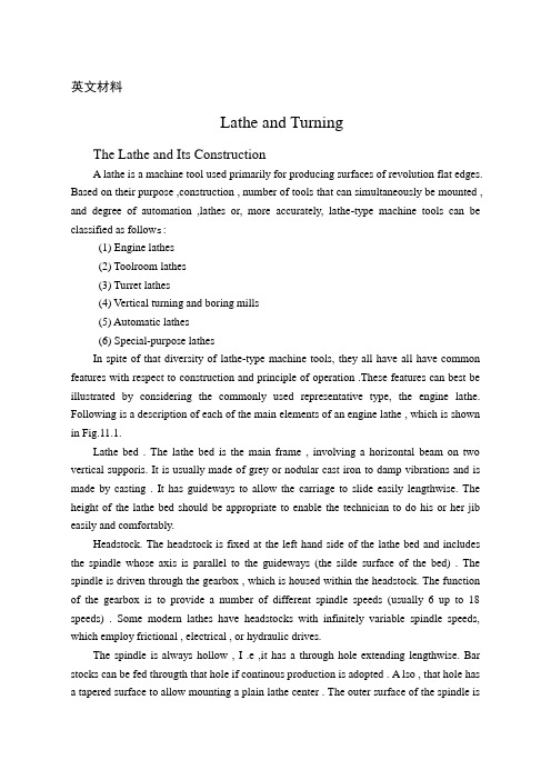
英文材料Lathe and TurningThe Lathe and Its ConstructionA lathe is a machine tool used primarily for producing surfaces of revolution flat edges. Based on their purpose ,construction , number of tools that can simultaneously be mounted , and degree of automation ,lathes or, more accurately, lathe-type machine tools can be classified as follow s:(1) Engine lathes(2) Toolroom lathes(3) Turret lathes(4) Vertical turning and boring mills(5) Automatic lathes(6) Special-purpose lathesIn spite of that diversity of lathe-type machine tools, they all have all have common features with respect to construction and principle of operation .These features can best be illustrated by considering the commonly used representative type, the engine lathe. Following is a description of each of the main elements of an engine lathe , which is shown in Fig.11.1.Lathe bed . The lathe bed is the main frame , involving a horizontal beam on two vertical supporis. It is usually made of grey or nodular cast iron to damp vibrations and is made by casting . It has guideways to allow the carriage to slide easily lengthwise. The height of the lathe bed should be appropriate to enable the technician to do his or her jib easily and comfortably.Headstock. The headstock is fixed at the left hand side of the lathe bed and includes the spindle whose axis is parallel to the guideways (the silde surface of the bed) . The spindle is driven through the gearbox , which is housed within the headstock. The function of the gearbox is to provide a number of different spindle speeds (usually 6 up to 18 speeds) . Some modern lathes have headstocks with infinitely variable spindle speeds, which employ frictional , electrical , or hydraulic drives.The spindle is always hollow , I .e ,it has a through hole extending lengthwise. Bar stocks can be fed througth that hole if continous production is adopted . A lso , that hole has a tapered surface to allow mounting a plain lathe center . The outer surface of the spindle isthreaded to allow mounting of a chuck , a face plate , or the like .Tallstock . The tailstock assembly consists basically of three parts , its lower base, an intermediate part, and the quill . The lower base is a casting that can slide on the lathe bed along the guidewayes , and it has a clamping device to enable locking the entire tailstock at any desired location , depending upon the length of the workpiece . The intermediate parte is a casting that can be moved transversely to enable alignment of the axis of the the tailstock with that of the headstock . The third part, the quill, is a hardened steel tube, which can be moved longitudinally in and out of the intermediate part as required . This is achieved through the use of a handwheel and a screw , around which a nut fixed to the quill is can be locked at any point along its travel path by means of a clamping device.The carriage. The main function of the carriage is mounting of the cutting tools and generating longitudinal and /or cross feeds. It is actually an H-shaped block that slides on the lathe bed between the headstock and tailstock while being guided by the V-shaped guideways of the bed . The carriage can be moved either manually or mechanically by means of the apron and either the feed rod or the lead screw.When cutting screw threads, power is provided to the gearbox of the apron by the lead screw. In all other turning operations, it is the feed rod that drives the carriage. The lead screw goes through a pair o half nuts , which are fixed to the rear of the apron . When actuating a certain lever, the half nuts are clamped together and engage with the rotating lead screw as a single nut, which is fed , together with carriage, along the bed . when the lever is disengaged , the half nuts are released and the carriage stops. On the other hand , when the feed rod is used, it supplies power to the apron through a wrom gear . The latter is keyed to feed rod and travels with the apron along the feed rod , which has a keyway extending to cover its whole length. A modern lathe usually has a quick-change gearbox located under the headstock and driven from the spindle through a train of gears. It is connected to both the feed rod and the lead screw and enables selecting a variety of feeds easily and rapidly by simply shifting the appropriate levers, the quick-change gearbox is employed in plain turning, facing and thread cutting operations. Since that gearbox is linked to spindle, the distance that the apron (and the cutting tool) travels for each revolution of the spindle can be controlled and is referred to as the feed.Lathe Cutting ToolsThe shape and geometry of the lathe tools depend upon the purpose for which they are employed. Turning tools can be classified into tow main groups,namely,external cutting tools and internal cutting tools , Each of these groups include the following types of tools:Turning tools. Turing tools can be either finishing or rough turning tools . Rough turning tools have small nose radii and are used for obtaining the final required dimensions with good surface finish by marking slight depth of cut . Rough turning tools can be right –hand or left-hand types, depending upon the direction of feed. They can have straight, bent, or offset shanks.Facing tools . Facing tools are employed in facing operations for machining plane side or end surfaces. There are tools for machining left-hand-side surfaces and tools for right-hand-side surfaces. Those side surfaces are generated through the use of the cross feed, contrary to turning operations, where the usual longitudinal feed is used.Cutoff tools. Cutoff tools ,which are sometimes called parting tools, serve to separate the workpiece into parts and/or machine external annual grooves.Thread-cutting tools. Thread-cutting tools have either triangular, square, or tranpezoidal cutting edges, depending upon the cross section of the desired thread .Also , the plane angles of these tools must always be identical to those of the thread forms. Thread-cutting tools have straight shanks for external thread cutting and are of the bent-shank type when cutting internal threads .Form tools. Form tools have edges especially manufactured to take a certain form, which is opposite to the desired shape of the machined workpiece . An HSS tools is usually made in the form of a single piece ,contrary to cemented carbides or ceramic , which are made in the form of tipes. The latter are brazed or mechanically fastened to steel shanks. Fig.11.2 indicates an arrangement of this latter type, which includes the carbide tip , the chip breaker ,the pad ,the clamping screw (with a washer and a nut ) , and the shank.. As the name suggests, the function of the chip breaker is to break long chips every now and then , thus preventing the formation of very long twisted ribbons that may cause problems during the machining operations . The carbide tips ( or ceramic tips ) can have different shapes, depending upon the machining operations for which they are to be employed . The tips can either be solid or with a central through hole ,depending on whether brazing or mechanical clamping is employed for mounting the tip on the shank.Lathe OperationsIn the following section , we discuss the various machining operations that can be performed on a conventional engine lathe. It must be borne in mind , however , that modern computerized numerically controlled lathes have more capabiblities and do other operations ,such as contouring , for example . Following are conventional lathe operations.Cylindrical turning . Cylindrical turning is the the simplest and the most common ofall lathe operations . A single full turn of the workpiece generate a circle whose center falls on the lathe axis; this motion is then reproduced numerous times as a result of the axial feed motion of the tool. The resulting machining marks are , therefore ,a helix having a very small pitch, which is equal to the feed . Consequently , the machined surface is always cylindrical.The axial feed is provided by the carriage or the compound rest , either manually or automatically, whereas the depths of cuts is controlled by the cross slide . In roughing cuts , it is recommended that large depths of cuts (up to 0.25 in. or 6 mm, depending upon the workpiece material) and smaller feeds would be used. On the other hand , very fine feeds, smaller depth of cut (less than 0.05in. , or 0.4 mm) , and high cutting speeds are preferred for finishing cuts.Facing . The result of a facing operation is a flat surface that is either the whole end surface of the workpiece or an annular intermediate surface like a shoulder . During a facing operation ,feed is provided by the cross slide, whereas the depth of cut is controlled by the carriage or compound rest . Facing can be carried out either from the periphery in ward or from the center of the workpiece outward . It is obvious that the machining marks in both cases tack the form of a spiral. Usually, it is preferred to clamp the carriage during a facing operation, since the cutting force tends to push the tool ( and , of course , the whole carriage ) away from the workpiece . In most facing operations , the workpiece is held in a chuck or on a face plate.Groove cutting. In cut-off and groove-cutting operations ,only cross feed of the tool is employed. The cut-off and grooving tools , which were previously discussed, are employed.Boring and internal turning . Boring and internal are performed on the internal surfaces by a boring bar or suitable internal workpiece is solid, a drilling operation must be performed first . The drilling tool is held in the tailstock, and latter is then fed against the workpiece.Taper turning . Taper turning is achieved by driving the tool in a direction that is not paralled to the lathe axis but inclined to it with an angle that is equal to the desired angle of the taper . Following are the different methods used in taper-turning practice: Rotating the disc of the compound rest with an angle to half the apex angle of the cone . Feed is manually provided by cranking the handle of the compound rest . This method is recommended for taper turning of external and internal surfaces when the taper angle is relatively large.Employing special form tools for external , very short ,conical surfaces . The width ofthe workpiece must be slightly smaller than that of the tool ,and the workpiece is usually held in a chuck or clamped on a face plate . I n this case , only the cross feed is used during the machining process and the carriage is clamped to the machine bed .Offsetting the tailstock center . This method is employed for esternal tamper turning of long workpiece that are required to have small tamper angles (less than 8 ) . The workpiece is mounted between the two centers ; then the tailstock center is shifted a distance S in the direction normal to the lathe axis.Using the taper-turning attachment . This method is used for turning very long workpoece , when the length is larger than the whole stroke of the compound rest . The procedure followed in such cases involves complete disengagement of the cross slide from the carriage , which is then guided by the taper-turning attachment . During this process, the automatic axial feed can be used as usual . This method is recommend for very long workpiece with a small cone angle , i.e. , 8 through 10 .Thread cutting . When performing thread cutting , the axial feed must be kept at a constant rate , which is dependent upon the rotational speed (rpm) of the workpiece . The relationship between both is determined primarily by the desired pitch of the thread to be cut .As previously mentioned , the axial feed is automatically generated when cutting a thread by means of the lead screw , which drives the carriage . When the lead screw rotates a single revolution, the carriage travels a distance equal to the pitch of the lead screw rotates a single revolutional speed of the lead screw is equal to that of the spindle ( i. e . , that of the workpiece ), the pitch of the resulting cut thread is exactly to that of the lead screw . The pitch of the resulting thread being cut therefore always depends upon the ratio of the rotational speeds of the lead scew and the spindle :Pitch of the lead screw rpm of the workpiece = spindle-to-carriage gearing ratio Desired pitch of workpiece rpm of lead screwThis equation is usefully in determining the kinematic linkage between the lathe spindle and the lead screw and enables proper selection of the gear train between them .n thread cutting operations , the workpiece can either be held in the chuck or mounted between the two lathe centers for relatively long workpiece . The form of the tool used must exactly coincide with the profile the thread to be cut , I . e . , triangular tools must be used for triangular threads , and so on .Knurling . knurling is mainly a forming operation in which no chips are prodyced . Tt involves pressing two hardened rolls with rough filelike surfaces against the rotatingworkpiece to cause plastic deformation of the workpiece metal.Knurling is carried out to produce rough , cylindrical ( or concile )surfaces , which are usually used as handles . Sometimes , surfaces are knurled just for the sake of decoration ; there are different types of patterns of knurls from which to choose .Cutting Speeds and FeedsThe cutting speed , which is usually given in surface feet per minute (SFM), is the number of feet traveled in circumferential direction by a given point on the surface (being cut ) of the workpiece in one minute . The relationship between the surface speed and rpm can be given by the following equation :SMF =3.14*DNWhereD= the diameter of the workpiece in feetN=the rpmThe surface cutting speed is dependent primarily upon the machined as well as the material of the cutting and can be obtained from handbooks , information provided by cutting tool manufacturera , and the like . generally , the SFM is taken as 100 when machining cold-rolled or mild steel ,as 50 when machining tougher metals , and as 200 when machining sofer materials . For aluminum ,the SFMis usually taken as 400 or above . There are also other variables that affect the optimal value of the surface cutting speed . These include the tool geometry, the type of lubricant or coolant , the feed , and the depth of cut . As soon as the cutting sped is decided upon , the rotational speed (rpm) of the spindle can be obtained as follows :SFM =3.14*DThe selection of a suitable feed depends upon many factors , such as the required surface finish , the depth of cut , and the geometry of the tool used . Finer feeds produce better surface finish ,whereas higher feeds reduce the machining time during which the toolis in direct contact with the workpiece . Therefore ,it is generally recommended to use high feeds for roughing operations and finer feeds for finishing operations. Again, recommend values for feeds , which can be taken as guidelines , are found in handbooks and information booklets provided by cutting tool manufacturers.Here I want to introduce the drilling and milling :Drilling involves producing through or blind holes in a workpiece by forcing a tool , which rotates around its axis , against the workpiece .Consequently , the range of cutting from that axis of rotation is equal to the radius of the required hole .In practice , two symmetricalcutting edges that rotate about the same axis are employed .Drilling operations can be carried out by using either hand drills or drilling machines . The latter differ in size and construction . nevertheless , the tool always rotates around its axis while the workpiece is kept firmly fixed . this is contrary to drilling on a lathe .Cutting Tool for Drilling OperationsIn drilling operations , a cylindrical rotary-end cutting , called a drill , is employed . The drill can have either one or more cutting edges and corresponding flutes , which can be straight or helical . the function of the flutes is to provide outlet passages for the chips generated during the drilling operation and to allow lubricants and coolants to reach the cutting edges and the surface being machined . Following is a survey of the commonly used drills.Twist drill . The twist drill is the most common type of drill .It has two cutting edges and two helical flutes that continue over the length of the drill body , as shown in Fig 12.1 The drill also consist of a neck and a shake that can be either straight or tapered .In the latter case , the shank is fitted by the wedge action into the tapered socket of the spindle and has a tang , which goes into a slot in the spindle socket ,thus acting as a solid means for transmitting rotation . On the other hand , straight –shank drills are held in a drill chuck that is , in turn , fitted into the spindle socket in the same way as tapered shank drills.As can be seen in FIG.12.1 , the two cutting edges are referred to as the lips , and are connected together by a wedge , which is a chisel-like edge . The twist drill also has two margins , which enable proper guidance and locating of the drill while it is in operation . The tool point angle (TPA) is formed by the lips and is chosen based on the properties of the material to be cut . The usual TAP for commercial drills is 118 , which is appropriate for drilling low-carbon steels and cast irons . For harder and tougher metals , such as hardened steel , brasss and bronze , larger TPAs (130 OR 140 ) give better performance . The helix angle of the flutes of the commonly used twist drills ranges between 24 and 30 . When drilling copper or soft plastics , higher values for the helix angle are recommended (between 35 and 45).Twist drills are usually made of high speed steel ,although carbide tipped drills are also available . The size of twist drills used in industrial range from 0.01 up to 3.25 in . (i.e.0.25 up to 80 mm ) .Core drills . A core drill consists of the chamfer , body , neck ,and shank , as shown in Fig 12.2 . This type of drill may be have either three or four flutes and an equal number of margins , which ensure superior guidance , thus resulting in high machining accuracy . It can also be seen in Fig 12.2 that a core drill has flat end . The chamfer can have three or four cuttingedges or lips , and the lip angle may vary between 90 and 120 . Core drills are employed for enlarging previously made holes and not for originating holes . This type of drill is characterized by greater productivity , high machining accuracy , and superior quality of the drilled surfaces .Gun drills . Gun drills are used for drilling deep holes . All gun drills are straight fluted , and each has a single cutting edge . A hole in the body acts as a conduit to transmit coolant under considerable pressure to the tip of the drill .There are two kinds of gun drills , namely , the center cut gun drill used for drilling blind holes and the trepanning drill . The latter has a cylindrical groove at its center , thus generating a solid core , which guides the tool as it proceeds during the drilling operation.Spade drills . Spade drills are used for drilling large holes of 3.5 in .(90 mm ) or more . Their design results in a marked saving in cost of the tool as well as a tangible reduction in its weight , which facilitates its handling . moreover , this type of drill is easy to be ground .Milling and Milling CuttersMilling is a machining process that is carried out by means of a multiedge rotating tool known as a milling cutter . In this process ,metal removal is achieved through combining the rotary motion of the milling cutter and linear motions of the workpiece simultaneously . Milling operations are employed in producing flat , contoured and helical surfaces as well as for thread and gear and gear cutting operations.Each of the cutting edges of a milling cuter acts as an individual single point cutter when it engages with the workpiece metal . therefore , each of those cutting edges has the workpiece at a time ,heavy cuts can be taken without adversely affecting the tool life .In fact ,the permissible cutting speeds and feeds for milling are there to four times higher than those for turning or drilling .Moreover ,the quality of the surfaces machined by milling is generally superior of surfaces machined by turning shaping ,or drilling.A wide variety of milling cutters is available in industry .This, together with the fact that a milling machine is very versatile machine tool ,makes the milling machine the backbone of a machining workshop .As far as the direction of cutter rotation and workpiece feed are concerned , milling is performed by either of the following tow methods .Up milling (conventional milling). In up milling workpiece is fed against the direction of cutter rotation, as shown in Fig.12.3. As we can see in that figure ,the depth of cut (and consequently the load ) gradually increases on the successively engaged cutting edges . Therefore, the machining process involves no impact loading , thus ensuring smother operationof the machine tool and longer tool life .The quality of the machined surface obtained by up milling is not very high . Nevertheless , up milling is commonly used in industry , especially for rough cuts.Down milling (climb milling ). Ascan be seen in Fig 12.3, in down milling the cutter rotation coincides with the direction of feed at the contact point between the tool and the workpiece . It can also be seen that the maximum depts. Of cut is achieved directly as the cutter engages with the workpiece . This results in a kind of impact , or sudden loading . Therefore, this method cannot be used the milling machine is equipped with a backlash elimination on the feed screw . The advantages of this method include higher quality of machined surface and easier clamping of workpieces, since the cutting forces act downward .Types of Milling CuttersThere is a wide variety of milling cutter shapes .Each of them is designed to perform effectively a specific milling operations . Generally ,a milling cutter can be described as a multiedge cutting tool having the shape of a solid of revolution ,with the cutting teeth arranged either on the periphery or on an end face or on both . Following is a quick survery of the commonly used types of milling cutters.Plain milling cutter . a plain milling cutter is a disk – shaped cutting tool that may have either straight or helical teeth ,as shown in Fig .12.4 .This type is always mounted on horizontal milling machines and is used for maching flat surfaces.Face milling cutter . A face milling cutter is also used for maching flat surfaces. It is bolted at the end of a short arbor ., which is in turn mounted on a vertical milling machine . Fig 12.4 indicates a milling cuter of this type.Plain metal slitting saw cutter .Fig 12.4 indicates a plain metal slitting saw cutter . We can see that it actually involves a very thin plain milling cutter.Side milling cutter. A side milling cutter is used for cutting solts, grooves, and splines. As shown in Fig 12.4 ,it is quite similar to the plain milling cutter , the difference being that this type has teeth on the sides .As is the case wih the plain cutter , the cutting teeth can be straight or helical .Angle milling cutter . Angle milling cutter is employed in cutting dovetail grooves , ratchet wheels, and the like .Fig 12.4 indicates a milling cutter of this type.T slot cutter . As shown in Fig 12.4 ,a T slot cutter involves a plain milling cutter with an integral shaft normal to it .As the name suggests ,this type is used for milling T slots.End mill cutter . End mill cutters find common applications in cutting slots , grooves , flutes , splines ,pocketing work, and the like . Fig 12.4 indicates an end mill cutter . The latteris always mounted on a vertical milling machine and can have toe or four flutes , which may be either straight or helical .Form milling cutter . The teeth of a form milling cutter have a certain shape , which is identical to the section of the metal to be removed during the milling operation. Examples of this type include gear cutters ,gear hobs, convex and concave cutters ,and the like . Form milling cutters are mounted on horizontal milling machines.Materialas of Milling CuttersThe commonly used milling cutters are made of high speed steel , which is generally adequate for most jobs . Milling cutters tipped with sintered carbides or cast nonferrous alloys as cutting teeth are usually employed for mass production , where heavier cuts and / or high cutting speeds are required.Here I want to introduce the MaterialsTypes of MaterialsMaterials may be grouped in several ways . scientists often classify materials by their state : solid , liquid , or gas . They also separate them into organic (once living) and inorganic (never living) materials.For industrial purposes , materials are divided into engineering materials or nonengineering materials .Engineering materials are those used in manufacture and become parts of products . Nonengineering materials are the chemicals ,fuels , lubricants ,and other materials used in the manufacturing process, which do not become part of the product.Engineering materials may be further subdivided into : 1 , Metals 2, Ceramics 3, Composite 4, Polymers , etc .Metals and Metals AlloysMetals are elements that generally have good electrical and thermal conductivity . Many metals have high strength , high stiffness , and have good ductility . Some metals ,such as iron ,cobalt and nickel , are magnetic . At extremely low temperatures , some metals and intermetallic compounds become superconductors.What is the difference between an alloy and a pure metal ? Pure metals are elements which come from a particular area of the periodic table . Examples of pure metals include copper in electrical wires and aluminum in cooking foil and beverage cans. Alloys contain more than one metallic element . Their properties can be changed by changing the elements present in the alloy . Examples of metal alloys include stainless steel which is an alloy of iron ,nickel ,and gold jewelry which usually contains an alloy of gold and nickel.Why are metals and alloys used ? Many metals have high densities and used inapplications which require a high mass to volume ratio. Some metal alloys , such as those based on aluminum , have low densities and are used in aerospace applications for fuel economy. Many alloys also have high fracture toughness, which means they can withstand impact and are durable.What are some important properties of metals?Density is defined as a material is a mass divided by its volume . Most metals have relatively high densities ,especially compared to polymers . Materials with high densities often contain atoms with high atomic numbers , such as gold or lead . However, some metals such as aluminum or magnesium have low densities ,and are used in applications that require other metallic proerties but also require low weight.Fracture toughness can be described as a material‘s ability to avoid fracture, especially when a flaw is introduced .Metals can generally contain nicks and dents without weakening very much ,and are impact resistant .A football player counts on this when he trusts that his facemask won’t shatter.Plastic deformation is the ability of a material to bend or deform before breaking .As engineers , we usuall y design materials so that don’t deform under normal conditions . You don’t want you car to lean to the east after a strong west wind .However ,sometimes we can take advantage of plastic deformation. The crumple zones in a car absorb energy by undergoing plastic deformation before pass through.Alloy are compounds consisting of more than one metal one metal .Adding other metals can affect the density ,strength , fracture toughness , plastic deformation, electrical conductivity and environmental degradation .For example ,adding a small smount of iron to aluminum will make it stronger .Also , adding some chromium to steel will slow the rusting process, but will make it more brittle.。
机械加工刀具中英文对照外文翻译文献

(文档含英文原文和中文翻译)中英文对照外文翻译英文原文Selection of optimum tool geometry and cutting conditionsusing a surface roughness prediction model for end milling Abstract Influence of tool geometry on the quality of surface produced is well known and hence any attempt to assess the performance of end milling should include the tool geometry. In the present work, experimental studies have been conducted to see the effect of tool geometry (radial rake angle and nose radius) and cutting conditions (cutting speed and feed rate) on the machining performance during end milling of medium carbon steel. The first and second ordermathematical models, in terms of machining parameters, were developed for surface roughness prediction using response surface methodology (RSM) on the basis of experimental results. The model selected for optimization has been validated with the Chi square test. The significance of these parameters on surface roughness has been established with analysis of variance. An attempt has also been made to optimize the surface roughness prediction model using genetic algorithms (GA). The GA program gives minimum values of surface roughness and their respective optimal conditions.1 IntroductionEnd milling is one of the most commonly used metal removal operations in industry because of its ability to remove material faster giving reasonably good surface quality. It is used in a variety of manufacturing industries including aerospace and automotive sectors, where quality is an important factor in the production of slots, pockets, precision moulds and dies. Greater attention is given to dimensional accuracy and surface roughness of products by the industry these days. Moreover, surface finish influences mechanical properties such as fatigue behaviour, wear, corrosion, lubrication and electrical conductivity. Thus, measuring and characterizing surface finish can be considered for predicting machining performance.Surface finish resulting from turning operations has traditionally received considerable research attention, where as that of machining processes using multipoint cutters, requires attention by researchers. As these processes involve large number of parameters, it would be difficult to correlate surface finish with other parameters just by conducting experiments. Modelling helps to understand this kind of process better. Though some amount of work has been carried out to develop surface finish prediction models in the past, the effect of tool geometry has received little attention. However, the radial rake angle has a major affect on the power consumption apart from tangential and radial forces. It also influences chip curling and modifies chip flow direction. In addition to this, researchers [1] have also observed that the nose radius plays a significant role in affecting the surface finish. Therefore the development of a good model should involve the radial rake angle and nose radius along with other relevant factors.Establishment of efficient machining parameters has been a problem that has confronted manufacturing industries for nearly a century, and is still the subject of many studies. Obtaining optimum machining parameters is of great concern in manufacturing industries, where the economy of machining operation plays a key role in the competitive market. In material removal processes, an improper selection of cutting conditions cause surfaces with high roughness anddimensional errors, and it is even possible that dynamic phenomena due to auto excited vibrations may set in [2]. In view of the significant role that the milling operation plays in today’s manufacturing world, there is a need to optimize the machining parameters for this operation. So, an effort has been made in this paper to see the influence of tool geometry (radial rake angle and nose radius) and cutting conditions (cutting speed and feed rate) on the surface finish produced during end milling of medium carbon steel. The experimental results of this work will be used to relate cutting speed, feed rate, radial rake angle and nose radius with the machining response i.e. surface roughness by modelling. The mathematical models thus developed are further utilized to find the optimum process parameters using genetic algorithms.2 ReviewProcess modelling and optimization are two important issues in manufacturing. The manufacturing processes are characterized by a multiplicity of dynamically interacting process variables. Surface finish has been an important factor of machining in predicting performance of any machining operation. In order to develop and optimize a surface roughness model, it is essential to understand the current status of work in this area.Davis et al. [3] have investigated the cutting performance of five end mills having various helix angles. Cutting tests were performed on aluminium alloy L 65 for three milling processes (face, slot and side), in which cutting force, surface roughness and concavity of a machined plane surface were measured. The central composite design was used to decide on the number of experiments to be conducted. The cutting performance of the end mills was assessed using variance analysis. The affects of spindle speed, depth of cut and feed rate on the cutting force and surface roughness were studied. The investigation showed that end mills with left hand helix angles are generally less cost effective than those with right hand helix angles. There is no significant difference between up milling and down milling with regard tothe cutting force, although the difference between them regarding the surface roughness was large. Bayoumi et al.[4] have studied the affect of the tool rotation angle, feed rate and cutting speed on the mechanistic process parameters (pressure, friction parameter) for end milling operation with three commercially available workpiece materials, 11 L 17 free machining steel, 62- 35-3 free machining brass and 2024 aluminium using a single fluted HSS milling cutter. It has been found that pressure and friction act on the chip – tool interface decrease with the increase of feed rate and with the decrease of the flow angle, while the cutting speed has a negligible effect on some of the material dependent parameters. Process parameters are summarized into empirical equations as functions of feed rate and tool rotation angle for each work material. However,researchers have not taken into account the effects of cutting conditions and tool geometry simultaneously; besides these studies have not considered the optimization of the cutting process.As end milling is a process which involves a large number f parameters, combined influence of the significant parameters an only be obtained by modelling. Mansour and Abdallaet al. [5] have developed a surface roughness model for the end milling of EN32M (a semi-free cutting carbon case hardening steel with improved merchantability). The mathematical model has been developed in terms of cutting speed, feed rate and axial depth of cut. The affect of these parameters on the surface roughness has been carried out using response surface methodology (RSM). A first order equation covering the speed range of 30–35 m/min and a second order equation covering the speed range of 24–38 m/min were developed under dry machining conditions. Alauddin et al. [6] developed a surface roughness model using RSM for the end milling of 190 BHN steel. First and second order models were constructed along with contour graphs for the selection of the proper combination of cutting speed and feed to increase the metal removal rate without sacrificing surface quality. Hasmi et al. [7] also used the RSM model for assessing the influence of the workpiece material on the surface roughness of the machined surfaces. The model was developed for milling operation by conducting experiments on steel specimens. The expression shows, the relationship between the surface roughness and the various parameters; namely, the cutting speed, feed and depth of cut. The above models have not considered the affect of tool geometry on surface roughness.Since the turn of the century quite a large number of attempts have been made to find optimum values of machining parameters. Uses of many methods have been reported in the literature to solve optimization problems for machining parameters. Jain and Jain [8] have used neural networks for modeling and optimizing the machining conditions. The results have been validated by comparing the optimized machining conditions obtained using genetic algorithms. Suresh et al. [9] have developed a surface roughness prediction model for turning mild steel using a response surface methodology to produce the factor affects of the individual process parameters. They have also optimized the turning process using the surface roughness prediction model as the objective function. Considering the above, an attempt has been made in this work to develop a surface roughness model with tool geometry and cutting conditions on the basis of experimental results and then optimize it for the selection of these parameters within the given constraints in the end milling operation.3 MethodologyIn this work, mathematical models have been developed using experimental results with the help of response surface methodolog y. The purpose of developing mathematical models relating the machining responses and their factors is to facilitate the optimization of the machining process. This mathematical model has been used as an objective function and the optimization was carried out with the help of genetic algorithms.3.1 Mathematical formulationResponse surface methodology (RSM) is a combination of mathematical and statisticaltechniques useful for modelling and analyzing the problems in which several independent variables influence a dependent variable or response. The mathematical models commonly used are represented by:where Y is the machining response, ϕ is the response function and S, f , α, r are milling variables and ∈ is the error which is normally distributed about the observed response Y with zero mean.The relationship between surface roughness and other independent variables can be represented as follows, where C is a constant and a, b, c and d are exponents.To facilitate the determination of constants and exponents, this mathematical model will have to be linearized by performing a logarithmic transformation as follows:The constants and exponents C, a, b, c and d can be determined by the method of leastsquares. The first order linear model, developed from the above functional relationship using least squares method, can be represented as follows:where Y1 is the estimated response based on the first-order equation, Y is the measured surface roughness on a logarithmic scale, x0 = 1 (dummy variable), x1, x2, x3 and x4 arelogarithmic transformations of cutting speed, feed rate, radial rake angle and nose radius respectively, ∈ is the experimental error and b values are the estimates of corresponding parameters.The general second order polynomial response is as given below:where Y2 is the estimated response based on the second order equation. The parameters, i.e. b0, b1, b2, b3, b4, b12, b23, b14, etc. are to be estimated by the method of least squares. Validity of the selected model used for optimizing the process parameters has been tested with the help of statistical tests, such as F-test, chi square test, etc. [10].3.2 Optimization using genetic algorithmsMost of the researchers have used traditional optimization techniques for solving machining problems. The traditional methods of optimization and search do not fare well over a broad spectrum of problem domains. Traditional techniques are not efficient when the practical search space is too large. These algorithms are not robust. They are inclined to obtain a local optimal solution. Numerous constraints and number of passes make the machining optimization problem more complicated. So, it was decided to employ genetic algorithms as an optimization technique. GA come under the class of non-traditional search and optimization techniques. GA are different from traditional optimization techniques in the following ways:1.GA work with a coding of the parameter set, not the parameter themselves.2.GA search from a population of points and not a single point.3.GA use information of fitness function, not derivatives or other auxiliary knowledge.4.GA use probabilistic transition rules not deterministic rules.5.It is very likely that the expected GA solution will be the global solution.Genetic algorithms (GA) form a class of adaptive heuristics based on principles derived from the dynamics of natural population genetics. The searching process simulates the natural evaluation of biological creatures and turns out to be an intelligent exploitation of a random search. The mechanics of a GA is simple, involving copying of binary strings. Simplicity of operation and computational efficiency are the two main attractions of the genetic algorithmic approach. The computations are carried out in three stages to get a result in one generation or iteration. The three stages are reproduction, crossover and mutation.In order to use GA to solve any problem, the variable is typically encoded into a string (binary coding) or chromosome structure which represents a possible solution to the given problem. GA begin with a population of strings (individuals) created at random. The fitness of each individual string is evaluated with respect to the given objective function. Then this initial population is operated on by three main operators – reproduction cross over and mutation – to create, hopefully, a better population. Highly fit individuals or solutions are given the opportunity to reproduce by exchanging pieces of their genetic information, in the crossover procedure, with other highly fit individuals. This produces new “offspring” solutions, which share some characteristics taken from both the parents. Mutation is often applied after crossover by altering some genes (i.e. bits) in the offspring. The offspring can either replace the whole population (generational approach) or replace less fit individuals (steady state approach). This new population is further evaluated and tested for some termination criteria. The reproduction-cross over mutation- evaluation cycle is repeated until the termination criteria are met.中文翻译选择最佳工具,几何形状和切削条件利用表面粗糙度预测模型端铣刀具几何形状对工件表面质量产生的影响是人所共知的,因此,任何成型面端铣摘要: 刀具几何形状对工件表面质量产生的影响是人所共知的,因此,任何成型面端铣设计应包括刀具的几何形状。
机床刀具发展历程
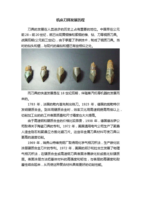
机床刀具发展历程刀具的发展在人类进步的历史上占有重要的地位。
中国早在公元前28~前20世纪,就已出现黄铜锥和紫铜的锥、钻、刀等铜质刀具。
战国后期(公元前三世纪),由于掌握了渗碳技术,制成了铜质刀具。
当时的钻头和锯,与现代的扁钻和锯已有些相似之处。
而刀具的快速发展是在18世纪后期,伴随蒸汽机等机器的发展而来的。
1783年,法国的勒内首先制出铣刀。
1923年,德国的施勒特尔发明硬质合金。
到采用硬质合金时,效率又比用高速钢提高两倍以上,切削加工出的的工件表面质量和尺寸精度也大大提高。
由于高速钢和硬质合金的价格比较昂贵,1938年,德国德古萨公司取得关于陶瓷刀具的专利。
1972年,美国通用电气公司生产了聚晶人造金刚石和聚晶立方氮化硼刀片。
这些非金属刀具材料可使刀具以更高的速度切削。
1969年,瑞典山特维克钢厂取得用化学气相沉积法,生产碳化钛涂层硬质合金刀片的专利。
1972年,美国的邦沙和拉古兰发展了物理气相沉积法,在硬质合金或高速钢刀具表面涂覆碳化钛或氮化钛硬质层。
表面涂层方法把基体材料的高强度和韧性,与表层的高硬度和耐磨性结合起来,从而使这种复合材料具有更好的切削性能。
由于在高温、高压、高速下,和在腐蚀性流体介质中工作的零件,其应用的难加工材料越来越多,切削加工的自动化水平和对加工精度的要求越来越高。
在选择刀具的角度时,需要考虑多种因素的影响,如工件材料、刀具材料、加工性质(粗、精加工)等,必须根据具体情况合理选择。
常见的刀具材料:高速钢,硬质合金(含金属陶瓷),陶瓷,CBN(立方氮化硼),PCD(聚晶金刚石),因其硬度一个比一个硬,所以一般而言,切削速度也一个比一个高。
刀具材料性能解析高速钢:可分为普通高速钢和高性能高速钢。
普通高速钢,如W18Cr4V广泛用于制造各种复杂刀具。
其切削速度一般不太高,切削普通钢料时为40-60m/min。
高性能高速钢,如W12Cr4V4Mo是在普通高速钢中再增加一些含碳量、含钒量及添加钴、铝等元素冶炼而成的。
外文翻译车床刀具早期的发展
The Early Development Of Numerically Controlled MachineToolsThe highly sophisticated CNC machine tools of today, in the vast and diverse range found throughout the field of manufacturing processing, started from very humble beginnings in a number of the major industrialized countries. Some of the earliest research and development work in this field was completed in USA and a mention will be made of the UK's contribution to this numerical control development.A major problem occurred just after the Second World War, in that progress in all areas of military and commercial development had been so rapid that the levels of automation and accuracy required by the modern industrialized world could not be attained from the lab our intensive machines in use at that time. The question was how to overcome the disadvantages of conventional plant and current manning levels. It is generally ackonwledged that the earliest work into numerical control was the study commissioned in 1947 by the US government. The study's conclusion was that the metal cutting industry throughout the entire country could not copy with the demands of the American Air Force, let alone the rest of industry! As a direct result of the survey, the US Air Force contracted the Persons Corporation to see if they could develop a flexible, dynamic, manufacturing system which would maximize productivity. The Massachusetts Institute of Technology (MIT) was sub-contracted into this research and development by the Parsons Corporation, during the period 1949-1951,and jointly they developed the first control system which could be adapted to a wide range of machine tools. The Cincinnati Machine Tool Company converted one of their standard 28 inch "Hydro-Tel" milling machines or a three-axis automatic milling made use of a servo-mechanism for the drive system on the axes. This machine made use of a servomechanism for the drive system on the axes, which controlled the table positioning, cross-slide and spindle head. The machine cab be classified as the first truly three axis continuous path machine tool and it was able to generate a required shape, or curve, by simultaneous slide way motions, if necessary.At about the same times as these American advances in machine tool control were taking Place, Alfred Herbert Limited in the United Kingdom had their first Mutinous path control system which became available in 1956.Over the next few years in both the USA and Europe, further development work occurred. These early numerical control developments were principally for the aerospace industry, where it was necessary to cut complex geometric shapes such as airframe components and turbine blades. In parallel with this development of sophisticated control systems for aerospace requirements, a point-to-point controller wasdeveloped for more general machining applications. These less sophisticated point-to-point machines were considerably cheaper than their more complex continuous path cousins and were used when only positional accuracy was necessary. As an example of point-to-point motion on a machine tool for drilling operations, the typical movement might be fast traverse of the work piece under the drill's position-after drilling the hole, anther rapid move takes place to the next hole's position-after retraction of the drill. Of course, the rapid motion of the slideways could be achieved by each axis in a sequential and independent manner, or simultaneously. If a separate control was utilisec for each axis, the former method of table travel was less essential to avoid any backlash in the system to obtain the required degree of positional accuracy and so it was necessary that the approach direction to the next point was always the same. The earliest examples of these cheaper point-to-point machines usually did not use recalculating ball screws; this meant that the motions would be sluggish, and sliderways would inevitably suffer from backlash, but more will be said about this topic later in the chapter. The early NC machines were, in the main, based upon a modified milling machine with this concept of control being utilized on turning, punching, grinding and a whole host of other machine tools later. Towards the end of the 1950s,hydrostatic slideways were often incorporated for machine tools of highly precision, which to sonic extent overcame the section problem associated with conventional slideway response, whiles averaging-out slideway inaccuracy brought about a much increased preasion in the machine tool and improved their control characteristics allows "concept of the machining center" was the product of this early work, as it allowed the machine to manufacture a range of components using a wide variety of machining processes at a single set-up, without transfer of workpieces to other variety machine tools. A machining center differed conceptually in its design from that of a milling machine, In that the cutting tools could be changed automatically by the transfer machanism, or selector, from the magazine to spindle, or vice versa.In this ductively and the automatic tool changing feature enabled the machining center to productively and efficiently machine a range of components, by replacing old tools for new, or reselecting the next cutter whilst the current machining process is in cycle.In the mid 1960s,a UK company, Molins, introduced their unique "System 24" which was meant represent the ability of a system to machine for 24 hours per day. It could be thought of as a "machining complex" which allowed a series of NC single purpose machine tools to be linked by a computerized conveyor system. This conveyor allowed the work pieces to be palletized and then directed to as machine tool as necessary. This was an early, but admirable, attempt at a form of Flexible manufacturing System concept, but was unfortunately doomed to failure. Its principalweakness was that only a small proportion of component varieties could be machine at any instant and that even fewer work pieces required the same operations to be performed on them. These factors meant that the utilization level was low, coupled to the fact that the machine tools were expensive and allowed frequent production bottlenecks of work-in-progress to arise, which further slowed down the whole operation. The early to mid-1970s was a time of revolutionary in the area of machine tool controller development, when the term computerized numerical control (CNC) became a reality. This new breed of controllers gave a company the ability to change work piece geometries, together with programs, easily with the minimum of development and lead time, allowing it to be economically viable to machine small batches, or even one-off successfully. The dream of allowing a computerized numerical controller the flexibility and ease of program editing in a production environment became a reality when two ralated factors occurred.These were:the development of integrated circuits, which reduces electronics circuit size, giving better maintenance and allowing more standardization of desing; that general purpose computers were reduced in size coupled to the fact that their cost of production had fallen considerably.The multipie benefits of cheaper electorics with greater reliability have result in the CNC fitted to the machine tools today, with the power and sophistication progtessing considerably in the last few years, allowing an almost artificial intelligence(AI) to the latest systems. Over the years, the machine tools builders have produced a large diversity in the range of applications of CNC and just some of those development will be reviewed in Volume Ⅲ。
中英文中英文文献翻译-关于数控车床和换刀系统

英文原文On the NC lathe and tool changing systemCNC machine tool numerical control machine tools (Computer numerical control machine tools) abbreviation, is provided with a program control system of automatic machine tools. The logic control system can deal with the control code or other symbolic instruction specified program, and decoding the digital code, said information carrier, through the numerical control device input. After processing by CNC device control signals, control the machine movements, by drawing the shape and size requirements, will be automatically processed by the parts.Features: CNC machine tool operation and monitoring of all completed in the numerical control unit, it is the brain of CNC machine tools. Compared with the general machine tools, CNC machine tools has the following characteristics:● the processing object adaptability, adapt to the characteristics of mold products such as a single production, provide the appropriate processing method for die and mould manufacturing;● high machining accuracy, processing with stable quality;● can coordinate linkage, processing complex shape parts;● machining parts change, only need to change the program, can save the preparation time of production;● the machine itself high precision, rigi dity, can choose the amount of processing good, high productivity (typically 3 to 5 times that of ordinary machine tool);The machine is a high degree of automation, reducing labor intensity;● conducive to the production management modernization. The use of CNC machine tools and the standard code of digital information processing, information transmission, the use of computer control method, has laid the foundation for the integration of computer aided design, manufacturing and management;● on the operato rs of higher quality, higher demands for the repair of the technical staff;● high reliability.Composition: CNC machine tools in general by the input medium, man-machine interactive equipment, CNC equipment, feed servo drive system, spindle servo drive system, the auxiliary control device, feedback apparatus and adaptive control device etc.. [4] in NC machining, NC milling processing is the most complex, need to solve most problems. NC programming of NC line in addition to CNC milling, cutting, CNC EDM, CNC lathe, CNC grinding, each with its own characteristics, servo system is the role of the motion signal is converted into the machine moving parts from the numerical control device of pulse. Concrete has the following parts: the structure of CNC machine tools.Driver: he is driving parts of CNC machine tools, actuator, including spindle drive unit, feeding unit, spindle motor and feed motor. He through the electric or electro-hydraulic servo system to realize the spindle and feed drive under the control of numerical control device. When several feed linkage, can complete the positioning, processing line, plane curve and space curve.The main performance(1) the main dimensions.(2) the spindle system.(3) feed system.(4) tool system.(5) electrical. Including the main motor, servo motor specifications and power etc..(6) cooling system. Including the cooling capacity, cooling pump output.(7) dimensions. Expressed as length * width * height.Development trend of CNC lathe:High speed, precision, complex, intelligent and green is the general trend in the development of CNC machine tool technology, in recent years, made gratifying achievements in practicality and industrialization. Mainly in the:1 machine tool composite technology to further expand with the CNC machine tool technology, composite processing technology matures, including milling - car compound, car milling compound, car - boring - drill - gear cutting compound, composite grinding, forming, composite processing, precision and efficiency of machining is greatly improved. "One machine is a processing factory", "one card, complete processing" concept is being accepted by more people, the development of compound processing machine tool is the trend of diversified.Intelligent technology 2 CNC machine tools have a new breakthrough, in the performance of NC system has been reflected more. Such as: automatically adjust the interference anti-collision function, after the power of workpiece automatically exit safety power-off protection function, machining parts detection and automatic compensation function of learning, high precision machining parts intelligent parameter selection function, process automatic elimination of machine vibration functions into the practical stage, intelligent upgrade the function of machine and quality.The 3 robots enable flexible combination of flexible combination of higher efficiency of robot and the host are widely used, make flexible line more flexible, extending the function, flexible line shorten further, more efficient. Robot and machining center, milling composite machine, grinder, gear processing machine tool, tool grinding machine, electric machine, sawing machine, punching machine, laser cutting machine, water cutting machine etc. various forms of flexible unit and flexible production line has already begun the application.4 precision machining technology has the machining precision of CNC metal cutting machine tools from the yarn in the original (0.01mm) up to micron level (0.001mm), some varieties has reached about 0.05 μ M. Micro cutting and grinding machining of ultra precision CNC machine tools, precision can reach about 0.05 μ m, shape precision can reach about 0.01 μ M. Special processing precision by using optical, electrical, chemical, energy can reach nanomete r level (0.001 μ m). By optimizing the design of machine tool structure, machine tool parts of ultra precision machining and precision assembly, using high precision closed loop control and temperature, vibration and other dynamic error compensation technology, improve the geometric accuracy of machine tool processing, reduce the shape of error, surface roughness, and into the submicron, nano super finishing tiThe 5 functional component to improve the performance of functional components are at a high speed,high precision, high power and intelligent direction, and obtain the mature application. A full digital AC servo motor and drive device, high technology content of the electric spindle, linear motor, torque motor, linear motion components with high performance, application of high precision spindle unit and other function parts, greatly improving the technical level of CNC machine tools.The feed drive system of CNC lathe:Effect of feed drive system,The feed drive system of CNC machine tools will be received pulse command issued by the numerical control system, and the amplification and conversion machine movements carry the expected movement.Two, the feeding transmission system requirementsIn order to guarantee the machining accuracy of NC machine tool is high, the feed drive system of transmission accuracy, sensitivity high (fast response), stable work, high stiffness and friction and inertia small, service life, and can remove the transmission gap.Category three, feed drive system1, stepping motor servo systemGenerally used for NC machine tools.2, DC servo motor servo systemPower is stable, but because of the brush, the wear resulting in use need to change. Generally used for middle-grade CNC machine tools.3, AC servo motor servo systemThe application is extremely widespread, mainly used in high-end CNC machine tools.4, the linear motor servo systemNo intermediate transmission chain, high precision, the feed speed, no length limit; but the poor heat dissipation, protection requirements are particularly high, mainly used for high-speed machine.Driving component four, feed system1, the ball screw nut pairNC machining, the rotary motion into linear motion, so the use of screw nut transmission mechanism. NC machine tools are commonly used on the ball screw, as shown in Figure 1-25, it can be a sliding friction into rolling friction, meet the basic requirements of the feed system to reduce friction. The transmission side of high efficiency, small friction, and can eliminate the gap, no reverse air travel; but the manufacturing cost is high, can not lock, size is not too big, generally used for linear feed in small CNC machine tool.2, rotary tableIn order to expand the scope of the process of NC machine tools, CNC machine tools in addition to make linear feed along the X, Y, Z three coordinate axes, often also need a circumferential feed movement around Y or Z axis. Circular feed motion of CNC machine tools in general by the rotary table to realize, for machining center, rotary table has become an indispensable part of.Rotary table of commonly used CNC machine tools in the indexing table and NC rotary table.(1) indexing tableIndexing table can only finish dividing movement, not circular feed, it is in accordance with theinstructions in the NC system, when indexing will work together with the workpiece rotation angle. When indexing can also use manual indexing. Provisions of indexing table is generally only rotary angle (such as 90, 60 and 45 degree).(2) NC rotary tableNC rotary table appearance similar to the indexing table, but the internal structure and function is not the same. The main function of the NC rotary table is based on the numerical control device sends command pulse signal, complete circumferential feed movement, various arc processing and surface processing, it can also be graduation work.3, guideRail is an important part of feed drive system, is one of the basic elements of the structure of machine tool, rigidity, precision and accuracy of NC machine tool which determines to a large extent retention. At present, guide the NC machine tool are sliding rail, rolling guideway and hydrostatic guideway.(1) sliding guideSliding guide rail has the advantages of simple structure, easy manufacture, good stiffness, vibration resistance and high performance, widely used in CNC machine tools, the use of most metal plastic form, known as the plastic guide rail, as shown in figure 1-26.On characteristics of the plastic sliding guide: friction characteristic is good, good wear resistance, stable movement, good manufacturability, low speed.(2) rolling guideRolling guide is placed in the rail surface between the ball, roller or needle roller, roller, the rolling friction instead of sliding surface of the guide rail between wipe.Rolling guide rail and the sliding rail, high sensitivity, small friction coefficient, and the dynamic, static friction coefficient is very small, so the motion is uniform, especially in the low speed movement, the stick-slip phenomenon is not easy to occur; high posit ioning accuracy, repeatability positioning accuracy is up to 0.2 μ m; traction force is small, wear small, portable in movement; good precision, long service life. But the vibration of rolling guide, high requirements on protection, complicated structure, difficult manufacture, high cost Automatic tool changer:One, the function of automatic tool changerAutomatic tool changing device can help save the auxiliary time of CNC machine tools, and meet in an installation completed procedure, step processing requirements.Two, on the requirement of automatic tool changerNumerical control machine tool for automatic tool changer requirement is: tool change quickly, time is short, high repetitive positioning accuracy, tool storage capacity is sufficient, small occupation space, stable and reliable work.Three, change the knife form1, rotary cutter replacementIts structure is similar to the ordinary lathe turret saddle, according to the processing of different objects can be designed into square or six angle form, consists of the NC system sends out the instruction to the rotarycutter.2, the replacement of the spindle head tool changeThe spindle head pre-loaded required tools, in order to machining position, the main motor is switched on, drives the cutter to rotate. The advantage of this method is that eliminates the need for automatic clamping, cutting tool, clamping and cutting tool moving and a series of complex operation, reduce tool change time, improve the reliability of the tool change.3, the use of changing toolThe processing required tools are respectively arranged in the standard tool, adjust the size of the machine after certain way add to the knife, the exchange device from the knife and the spindle take knife switch.Four, the tool switching deviceAutomatic tool change device, device for knife library and the main shaft transmission and handling tool for tool exchange device. Tool exchange often have two kinds: mechanical hand tool exchange and by relative motion of knife and machine tool spindle exchange tool (cutter to the spindle tool change or movement of the spindle to the knife knife tool change position), the mechanical hand tool change is most common.Five, the knifeThe knife is one of the most important parts in automatic tool changer, have great influence on the overall design of NC machine tool and its capacity, layout and structure.1, the capacity of the tool storageA number of knife inventory cutters, generally depending on the processing requirements. The capacity of small knife, can not meet the processing needs; capacity is too large, will make the knife database size, covers an area of large, tool selection process for a long time, and the knife library utilization rate is low, the structure is too complex, causing great waste.2, the knife typeGenerally, the chain disc and drum type knife several.Disc cutter tool was circular arrangement, low utilization of space, size is not large but simple structure.Chain magazine compact structure, large capacity, link shape can also be random bed made of various forms and flexible layout, but also will change the cutter location prominent for tool change, widely used.Drum type or lattice type knife, covers an area of small, compact structure, large capacity, but cutter selection, tool movements are complicated, for centralized knife system for FMS.3, tool selectionOften order tool selection and random selection tool two.The order of tool selection is before processing, the processing required tools to process sequence of insert knife knife, order not wrong, processing adjust knife in order. The work piece changes, the need to reset the tool sequence, the operation is simple, and the processing tool with a workpiece can not be repeated use.A knife is the cutting tool has its own code, optional and can be repeatedly used in processing, also do not put in the fixed knife, knife, the knife is convenient.Technology file is the guiding file workers during processing, process scheme is reasonable, not only affect the efficiency of NC machining, and will directly affect the machining quality. Therefore, before NCprogramming, NC machining process follows the process of certain principles and combined with the characteristics of CNC lathe seriously and develop in detail the good parts.In the CNC lathe processing parts, should according to the principle of dividing process concentrated, in a fixture as far as possible to complete the most or even all of the surface processing. Part positioning, according to the structure of different shapes, usually cylindrical, face or end clamping, and strive to design basis, process reference and programming the unification datum.The main contents are: analysis of NC machining technology of part drawings, clear processing content; determination method, workpiece on lathe the surface processing sequence and tool feed line and cutting tools, fixtures and cutting the amount of choice.Analysis, part drawing processIn the machining process planning of parts, first of all to carry on in-depth analysis to the processing object. For NC turning process should consider the following aspects:1 reading part drawing, analysis of geometric conditions of part contourIn turning process of manual programming, to calculate each node coordinates; in automatic programming, to define the components outline all geometric elements. Therefore, in the analysis of parts should pay attention to:Parts of the map is missing a dimension, the geometric conditions are not sufficient to constitute the part outline, influence;Map location map parts of the ambiguity or dimension is not clear, so that the program can't start;The part drawing geometry given is not reasonable, resulting in mathematical difficulties.The part drawing dimensioning methods should adapt to the characteristics of CNC lathe processing, should size or directly given coordinate dimension with the same standard.2 dimensional accuracy requirementsAnalysis of the pattern of parts size precision requirements, to determine whether achieve the turning process, and determine the process method to control the dimension precision. In the analysis process, but also can convert some dimensions such as size, incremental and absolute size and dimension chain calculation. In the use of NC lathe turning parts, average value of components often required size and maximum and minimum limit of size size as the basis of programming.3 shape and position accuracy requirementsPattern of parts tolerance of shape and location given is important foundation to ensure the parts precision. When machining parts, to determine the location reference and measurement reference according to the requirements, can also carry out some technical processing according to the special needs of CNC lathe parts, in order to control effectively the shape and position accuracy.4 requirements of surface roughnessSurface roughness is an important requirement of micro precision parts of the surface, but also the reasonable selection of NC lathe, cutting tools and cutting the amount determined on the basis of.5 material and heat treatment requirementsThe part drawing on material and heat treatment given requirements, is the choice of cutter, CNC lathe,cutting the amount determined on the basis of model.Automatic tool changing system is mainly to process the required tools, transmitted to the spindle clamping mechanism from the knife. A TC system by knife library, manipulator, which consists of a driving system. Basic requirements: tool 1 short change time 2 tool with high repeat positioning accuracy of 3 sufficient storage capacity of 4 knife library covers an area of small (compact) 5 safe and reliable.The knife is a knife storage device provides the required automatic machining process and tool changing needs; the automatic tool change mechanism and can put the tool storage of the knife. Controlled by the computer program, can complete a variety of machining different needs, such as milling, drilling, boring, tapping etc.. Shorten the process, reduce the production cost.The knife is a knife storage location, and according to the control program, to determine the correct tool to position, to exchange tool; tool change mechanism is the implementation of tool exchange action. The knife must exist at the same time and tool change mechanism, if no knife library processing required tools can't reserve; without tool change mechanism, then the processing required tools not knife Kuyi order replacement, and reduce non-cutting time to lose.Rotary motion of the knife is composed of a three-phase asynchronous motor with brake of the power source, the three-phase power supply through the AC contactor is supplied to the motor brake open, then the knife library operation, cut off the three-phase power supply brake locking, knife immediately stop running. Through the logical combination of indexing disk motion and related test element group, can make each Daotao accurate stop at the tool change position. Knife stopped at the tool change position, controlled by the cylinder sleeve in horizontal or vertical state, to facilitate mechanical hand for the knife, knife indexing table can be clockwise or counterclockwise rotation, which can search in the shortest possible time to the tool to change. The driving system of NC machine tool automatic tool changing system with hydraulic mechanism, pressure mechanism, electric cam mechanism. Nowadays the cam tool changer is used widely. Really fast, but no other consumable parts and maintenance requirements change, the failure rate at least, life of more than one million times. Speed changer system for rapid automatic tool changing technology is mainly aimed to reduce the processing time, the comprehensive consideration of various factors of machine tools, complete the technical method of tool exchange in the shortest possible time. The machine has the following features: 1 knife arm is short 2 knife arm is not necessarily linear 3 two knife may mutually perpendicular 4 cam box is small and mobile. Its main purpose is to let the knife, the movable parts of small moment of inertia, in order to achieve the purpose of quick change knife. Foundation to improve the automatic changing device in the traditional method of knife cutter changing speed of increase movement speed, or the mechanism action faster and a driving element. For example, change the knife speed mechanical cam structure is higher than that of hydraulic and pneumatic structure. According to the high speed machine tool structure design of knife and the knife changing device of form and position. For example, the knife machine tools and tool replacing device installed at the side of an upright post, in the high speed machine tool is more feeding movable column, in order to reduce the mass of the moving parts, the knife and tool replacing device should not be installed on the upright post. The formation of the optimal cutting parameters. Machining and turning centers is composed of mechanical equipment and CNC system, high efficiency, high precision of automatic machine for machiningof complex parts. This machine can be installed several knife, automatic tool change, installed in a card, to complete the milling, boring, vehicle processing, drilling, expansion joints, tapping. The reason why this kind of processing capacity, it is because it has a set of automatic tool changer. Automatically switch to the device in a variety of forms, is the main component of the knife, a manipulator and a driving device, although the tool change, tool selection, tool storage structure, mechanical hand types are different, but all is in the numerical control device and the programmable controller control, by the motor or hydraulic or pneumatic actuator driven knife base and the manipulator and the exchange tool selection. We refer to this as continuous processing to achieve a variety of process, the processing center or turning center, device selection and exchange for tool called automatic knife device (automatic tool change ATC). The main part of ATC is the knife, a manipulator and a driving device. The knife is the function of storage tool and knife next to be used accurately to the tool change position, in exchange for tool changing manipulator to complete the old and new tool. When the tool storage capacity is large, often far away from the main configuration and integral movement is not easy, it needs between the spindle and the tool library configuration tool change mechanism to perform the action of changing knife.The manipulator assembly is the current research focus, foreign study used camera and a force sensor and a microcomputer connected together, can identify the parts of the range to reach the aim of inlaid. At present the industry manipulator is mainly used for machining, casting, heat treatment, regardless of the number, variety and performance still can not meet the needs of industrial development. The main is to gradually expand the scope of application, mechanical hand to focus on the development of casting, heat treatment, in order to reduce labor intensity, improve working conditions, the application of special mechanical hand at the same time, the development of general machinery corresponding hand, has the condition to develop teaching manipulator, computer control of manipulator and the combination of manipulator. The motion of the manipulator components, such as expansion, swing, lifting, shifting, pitch mechanism and a clamping mechanism of different types according to the design into a common mechanism, typical, so according to the different requirements of different types of clamping mechanism, can form different manipulator path. Both for the design and manufacture, is convenient for the replacement of the workpiece, expand the scope of application. At the same time to improve speed, reduce the impact, correct positioning, in order to better play the role of manipulator. In addition to research on servo type, memory reappearance type, as well as with tactile, visual properties such as mechanical hand, and consider the connected with computer, and gradually become a basic unit of the whole machinery manufacturing system. In the mechanical manufacturing industrial manipulator is used more, faster development. Now mainly used for machine, horizontal forging press feeding and discharging, and spot welding, paint spraying operations, which can be used to complete the operation in advance in accordance with the specified procedure. In addition, the development trend of foreign manipulator is developing manipulator has some kind of intelligence. It has the ability to change sensor, can feedback to external conditions, make corresponding changes. Such as the location of a deviation, which can correct and self detection, focus on visual function and tactile function research. At present, have made certain achievements. Visual function is mounted on a manipulator has a TV camera and optical rangefinder (i.e. distance sensor) and micro computer. Work is a television camera will object image into the video signal, andthen sent to the computer, in order to analyze the types of objects, size, color and location, and sends out the instruction to control the manipulator to work. Tactile function is tactile feedback control device is mounted on a manipulator. When the mechanical hand first finger to find work, produce the tactile effect through the pressure sensitive element is arranged on the finger, and then into the front, seize the workpiece. Hand grasping force control through the sensitive element is arranged on the finger, to achieve automatic adjustment grip size. In short, as the capacity of assembly work development of mechanical sensing technology will also further improve the hand. More important is the manipulator, the flexible manufacturing system and flexible manufacturing unit combination, so as to fundamentally change the current manufacturing system operation state.中文译文关于数控车床和换刀系统数控机床是数字控制机床(Computer numerical control machine tools)的简称,是一种装有程序控制系统的自动化机床。
车床加工(中英文对照)

车床加工J.J.Raphael and J.A.M.Boulet刊登于2002年12月5日,2003年5月14日修订车床主要是为了进行车外圆、车端面和镗孔等项工作而设计的机床。
车削很少在其他种类的机床上进行,而且任何一种其他机床都不能像车床那样方便地进行车削加工。
由于车床还可以用来钻孔和铰孔,车床的多功能性可以使工件在一次安装中完成几种加工。
因此,在生产中使用的各种车床比任何其他种类的机床都多。
车床的基本部件有:床身、主轴箱组件、尾座组件、溜板组件、丝杠和光杠。
床身是车床的基础件。
它通常是由经过充分正火或时效处理的灰铸铁或者球墨铁制成。
它是一个坚固的刚性框架,所有其他基本部件都安装在床身上。
通常在床身上有内外两组平行的导轨。
有些制造厂对全部四条导轨都采用导轨尖朝上的三角形导轨(即山形导轨) ,而有的制造厂则在一组中或者两组中都采用一个三角形导轨和一个矩形导轨。
导轨要经过精密加工以保证其直线度精度。
为了抵抗磨损和擦伤,大多数现代机床的导轨是经过表面淬硬的,但是在操作时还应该小心,以避免损伤导轨。
导轨上的任何误差,常常意味着整个机床的精度遭到破坏。
主轴箱安装在内侧导轨的固定位置上,一般在床身的左端。
它提供动力,并可使工件在各种速度下回转。
它基本上由一个安装在精密轴承中的空心主轴和一系列变速齿轮(类似于卡车变速箱)所组成。
通过变速齿轮,主轴可以在许多种转速下旋转。
大多数车床有8~12种转速,一般按等比级数排列。
而且在现代机床上只需扳动2~4个手柄, 就能得到全部转速。
一种正在不断增长的趋势是通过电气的或者机械的装置进行无级变速。
由于机床的精度在很大程度上取决于主轴,因此,主轴的结构尺寸较大,通常安装在预紧后的重型圆锥滚子轴承或球轴承中。
主轴中有一个贯穿全长的通孔,长棒料可以通过该孔送料。
主轴孔的大小是车床的一个重要尺寸,因此当工件必须通过主轴孔供料时,它确定了能够加工的棒料毛坯的最大尺寸。
尾座组件主要由三部分组成。
车床的发展简史及发展类型
车床的发展简史及发展类型车床是一种用来加工金属、木材等材料的机床,它是机械加工行业中一种重要的设备。
本文将为您介绍车床的发展简史以及不同类型的发展。
一、车床的发展简史车床的历史可以追溯到公元前1200年左右的古埃及时期,当时人们使用手动操作的车床进行简单的木材加工。
随着时间的推移,车床逐渐发展壮大。
在公元前4世纪,古希腊工程师Archytas设计了一种由人力驱动的车床,使得车床的操作更加高效。
到了公元前1世纪,罗马工程师Vitruvius发明了一种由水力驱动的车床,进一步提高了生产效率。
到了中世纪,车床的发展进入了一个新的阶段。
在14世纪,德国工程师Jacques Besson设计了一种由脚踏踩动的车床,使得操作更加方便。
到了16世纪,德国工程师Georg Schawanhardt发明了一种由蒸汽驱动的车床,这标志着车床进入了工业化生产的时代。
随着工业革命的到来,车床的发展进入了一个新的阶段。
在18世纪末,英国工程师Henry Maudslay设计了一种由蒸汽机驱动的车床,这种车床具有更高的精度和稳定性,成为当时最先进的车床。
到了19世纪,随着电力的普及,电动车床开始出现,并逐渐取代了蒸汽驱动的车床。
二、车床的发展类型1. 手动车床:手动车床是最早出现的车床类型,由操作人员手动控制工件的加工过程。
手动车床操作简单,适用于小批量生产和个体加工。
2. 数控车床:数控车床是一种由计算机控制的车床,通过预先编程的指令来控制工件的加工。
数控车床具有高精度、高效率和灵活性的特点,适用于大批量生产和复杂零件加工。
3. 自动车床:自动车床是一种能够自动进行工件加工的车床,它通过一系列的机械装置和控制系统来实现自动化加工。
自动车床适用于大规模生产和重复加工。
4. 多轴车床:多轴车床是在传统车床的基础上增加了多个工作轴,可以同时进行多个方向的加工。
多轴车床具有更高的加工效率和多样化的加工能力,适用于复杂零件加工和高精度加工。
- 1、下载文档前请自行甄别文档内容的完整性,平台不提供额外的编辑、内容补充、找答案等附加服务。
- 2、"仅部分预览"的文档,不可在线预览部分如存在完整性等问题,可反馈申请退款(可完整预览的文档不适用该条件!)。
- 3、如文档侵犯您的权益,请联系客服反馈,我们会尽快为您处理(人工客服工作时间:9:00-18:30)。
The Early Development Of Numerically Controlled Machine ToolsThe highly sophisticated CNC machine tools of today, in the vast and diverse range found throughout the field of manufacturing processing, started from very humble beginnings in a number of the major industrialized countries. Some of the earliest research and development work in this field was completed in USA and a mention will be made of the UK's contribution to this numerical control development.A major problem occurred just after the Second World War, in that progress in all areas of military and commercial development had been so rapid that the levels of automation and accuracy required by the modern industrialized world could not be attained from the lab our intensive machines in use at that time. The question was how to overcome the disadvantages of conventional plant and current manning levels. It is generally ackonwledged that the earliest work into numerical control was the study commissioned in 1947 by the US government. The study's conclusion was that the metal cutting industry throughout the entire country could not copy with the demands of the American Air Force, let alone the rest of industry! As a direct result of the survey, the US Air Force contracted the Persons Corporation to see if they could develop a flexible, dynamic, manufacturing system which would maximize productivity. The Massachusetts Institute of Technology (MIT) was sub-contracted into this research and development by the Parsons Corporation, during the period 1949-1951,and jointly they developed the first control system which could be adapted to a wide range of machine tools. The Cincinnati Machine Tool Company converted one of their standard 28 inch "Hydro-Tel" milling machines or a three-axis automatic milling made use of a servo-mechanism for the drive system on the axes. This machine made use of a servomechanism for the drive system on the axes, which controlled the table positioning, cross-slide and spindle head. The machine cab be classified as the first truly three axis continuous path machine tool and it was able to generate a required shape, or curve, by simultaneous slide way motions, if necessary.At about the same times as these American advances in machine tool control were taking Place, Alfred Herbert Limited in the United Kingdom had their first Mutinous path control system which became available in 1956.Over the next few years in both the USA and Europe, further development work occurred. These early numerical control developments were principally for the aerospace industry, where it was necessary to cut complex geometric shapes such as airframe components and turbine blades. In parallel with this development of sophisticated control systems for aerospace requirements, a point-to-point controller was developed for more general machining applications. These less sophisticated point-to-point machines were considerably cheaper than their more complex continuous path cousins and were used when only positional accuracy was necessary. As an example of point-to-point motion on a machine tool for drilling operations, the typical movement might be fast traverse of the work piece under the drill's position-after drilling the hole, anther rapid move takes place to the next hole's position-after retraction of the drill. Of course, the rapid motion of the slideways could be achieved by each axisin a sequential and independent manner, or simultaneously. If a separate control was utilisec for each axis, the former method of table travel was less essential to avoid any backlash in the system to obtain the required degree of positional accuracy and so it was necessary that the approach direction to the next point was always the same. The earliest examples of these cheaper point-to-point machines usually did not use recalculating ball screws; this meant that the motions would be sluggish, and sliderways would inevitably suffer from backlash, but more will be said about this topic later in the chapter.The early NC machines were, in the main, based upon a modified milling machine with this concept of control being utilized on turning, punching, grinding and a whole host of other machine tools later. Towards the end of the 1950s,hydrostatic slideways were often incorporated for machine tools of highly precision, which to sonic extent overcame the section problem associated with conventional slideway response, whiles averaging-out slideway inaccuracy brought about a much increased preasion in the machine tool and improved their control characteristics allows "concept of the machining center" was the product of this early work, as it allowed the machine to manufacture a range of components using a wide variety of machining processes at a single set-up, without transfer of workpieces to other variety machine tools. A machining center differed conceptually in its design from that of a milling machine, In that the cutting tools could be changed automatically by the transfer machanism, or selector, from the magazine to spindle, or vice versa.In this ductively and the automatic tool changing feature enabled the machining center to productively and efficiently machine a range of components, by replacing old tools for new, or reselecting the next cutter whilst the current machining process is in cycle.In the mid 1960s,a UK company, Molins, introduced their unique "System 24" which was meant represent the ability of a system to machine for 24 hours per day. It could be thought of as a "machining complex" which allowed a series of NC single purpose machine tools to be linked by a computerized conveyor system. This conveyor allowed the work pieces to be palletized and then directed to as machine tool as necessary. This was an early, but admirable, attempt at a form of Flexible manufacturing System concept, but was unfortunately doomed to failure. Its principal weakness was that only a small proportion of component varieties could be machine at any instant and that even fewer work pieces required the same operations to be performed on them. These factors meant that the utilization level was low, coupled to the fact that the machine tools were expensive and allowed frequent production bottlenecks of work-in-progress to arise, which further slowed down the whole operation.The early to mid-1970s was a time of revolutionary in the area of machine tool controller development, when the term computerized numerical control (CNC) became a reality. This new breed of controllers gave a company the ability to change work piece geometries, together with programs, easily with the minimum of development and lead time, allowing it to be economically viable to machine small batches, or even one-off successfully. The dream of allowing a computerized numerical controller the flexibility and ease of program editing in a production environmentbecame a reality when two ralated factors occurred.These were:the development of integrated circuits, which reduces electronics circuit size, giving better maintenance and allowing more standardization of desing; that general purpose computers were reduced in size coupled to the fact that their cost of production had fallen considerably.The multipie benefits of cheaper electorics with greater reliability have result in the CNC fitted to the machine tools today, with the power and sophistication progtessing considerably in the last few years, allowing an almost artificial intelligence(AI) to the latest systems. Over the years, the machine tools builders have produced a large diversity in the range of applications of CNC and just some of those development will be reviewed in Volume Ⅲ。