USB Driver User Guide
USB驱动安装指南说明书
USB Driver Installation GuideCopyright and Technical SupportUSB Driver Installation GuideMTCMR-xx-All Versions, MTSMC-xx-IP/GP-All Versions, MTCBA-H3/EV1-U1, MTSMC-H3/EV1-U,S000507A, Revision ACopyrightThis publication may not be reproduced, in whole or in part, without prior expressed written permission from Multi-Tech Systems, Inc. All rights reserved.Copyright © 2011 by Multi-Tech Systems, Inc.Multi-Tech Systems, Inc. makes no representation or warranties with respect to the contents hereof and specifically disclaims any implied warranties of merchantability or fitness for any particular purpose.Furthermore, Multi-Tech Systems, Inc. reserves the right to revise this publication and to make changes from time to time in the content hereof without obligation of Multi-Tech Systems, Inc., to notify any person or organization of such revisions or changes. Check Multi-Tech’s Web site for current versions of our product documentation.Revision HistoryRevision Date DescriptionA10/19/11 Initial release.Trademarks and LogosThe Multi-Tech logo, SocketModem, and MultiModem are registered trademarks of Multi-Tech Systems, Inc. Windows is a registered trademark of Microsoft in the U.S. and other countries. Other trademarks and trade names mentioned in this publication belong to their respective owners.Contacting Multi-Tech SupportIn order to better serve our customers, manage support requests and shorten resolution times, we have created the online web portal allowing you to submit questions regarding Multi-Tech products directly to our technical support team. Get answers to your most complex questions, ranging from implementation, troubleshooting, product configuration, firmware upgrades and much more.To create an account and submit a Support Case on the Portal, visit https://Online Web Portal https://The Knowledge Base provides immediate answers to your questions and gives you access to support resolutions for all Multi-Tech products. Visit our support area on the website for other support services.Knowledge Base and Support Services /support.goWorld HeadquartersMulti-Tech Systems, Inc.2205 Woodale DriveMounds View, Minnesota 55112Phone: 763-785-3500 or 800-328-9717Fax: 763-785-9874Technical SupportBusiness Hours: M-F, 9am to 5pm CSTCountry By Email By PhoneEurope, Middle East, Africa: ********************.uk+(44) 118 959 7774U.S., Canada, all others: *********************(800) 972-2439 or (763) 717-5863WarrantyTo read the warranty statement for your product, please visit: /warranty.goContentsChapter 1 – Product Description (4)Introduction (4)Models and Build Option Descriptions (4)Chapter 2 – USB CDC-ACM Driver Installation on Windows (5)Introduction (5)Installing a Virtual COM Port (5)Installing the Modem Driver (6)Verifying That Your Modem Has Been Installed Successfully (9)Account Activation for Cellular Devices (9)Chapter 3 – USB Huawei Driver Installation on Windows (10)Introduction (10)Installing the Huawei Driver (10)Account Activation for Cellular Devices (11)Chapter 4 – Installing Drivers on Linux kernel 2.6.x (12)Introduction (12)Account Activation for Cellular Devices (12)IntroductionThe Multi-Tech® USB Driver Installation Guide provides driver installation procedures for the Multi-Tech SocketModem®, MultiModem® Cell and MultiModem® iCell products. This Installation Guide is organized into four chapters; Chapter 2 provides installation procedures for the USB CDC-ACM drivers on a Windows Operating System; Chapter 3 provides installation procedures for the Huawei drivers on a Windows Operating System; and finally Chapter 4 provides installation procedures on Linux Kernel 2.6.X and newer Operating Systems.The SocketModem models with Universal IP capabilities in a Windows environment use the USB CDC-ACM driver; SocketModem models without UIP capabilities in a Windows environment use the Huawei Driver; modem models in a Linux environment have the drivers embedded in the Linux Operating System. An example Linux installation, using Ubuntu Operating System version 11.04 with the Linux kernel 2.6.38 is provided in Chapter 4 for the Linux environment.After you have installed the modem driver, you need to activate your modem by going to the Multi-Tech Activation website and establishing an account with your cellular carrier.Models and Build Option DescriptionsCDC-ACM Drivers MTCMR-xx – All versionsMTSMC-xx-IP/GP – All versionsHuawei Drivers MTCBA-H3/EV1-U1MTSMC-H3/EV1-UIntroductionFor Windows XP (SP3 or greater), VISTA, 2003/2008 Server, Windows 7 (32-bit or 64-bit), run the automatic installer from the driver you just downloaded from the Multi-Tech website.Note: Certain versions of Windows have an issue with their CDC-ACM driver (Usbser.sys). If you are having connection problems (file download, web pages not loading) your version of Usbser.sys must be updated. Microsoft article 925681 documents this issue and provides a fix.After installing the virtual com port, the correct modem driver may be installed to the com port. This is covered below.Installing a Virtual COM PortYour downloaded driver files contain an installer program for current Windows operating systems (Windows XP and newer only) . Run install.bat from the VCOM_autoinstall directory you down loaded.1.Ensure that the USB cable is connected to your PC.2. For GSM build options, ensure that the SIM card is installed prior to powering up.3. From the Drivers folder, run the install.bat file to initiate the install.4.If any Windows Install Wizard pops up, close or cancel the wizard.5.Windows may pop-up a User Account Control window. Select the YES button to continue with the driverinstallation.6.Click on the Next button to start the driver pre-installation.Chapter 2 – USB CDC-ACM Driver Installation7.There will be a transitory screen, then the process will complete. Click on the Finish button.8.Next, continue with installing the modem driver.Installing the Modem Driver1.Click on the Control Panel button. On the Control Panel screen, double-click on Phone and Modem Options icon.Then click on the Modems tab.Chapter 2 – USB CDC-ACM Driver Installation 2. When this Phone and Modem Options screen appears, click on the Add button.3. On the Install New Modem screen, click Don’t detect my modem, I will select it from a list. Then click Next >.4. On the Install New Modem screen, click the Have Disk button to browse to the Driver folder on your local PC.Chapter 2 – USB CDC-ACM Driver Installation5. Browse to the Driver folder on local PC.6. Select the MTSMCIP_MTCMRIP.INF file. Then click OK.7. In the Models window, scroll down the list of Models and select the model that is applicable to your modem.Once you have selected your model, click on Next>.8. You will now have to choose which com port the MultiModem is connected to.If you know exactly which port your modem is on, click on that port; otherwise, go to Device Manager > Ports (COM & LPT) to verify which port your modem is installed on. Click Next>.Chapter 2 – USB CDC-ACM Driver Installation9. To finish the install, click on Finish.You have now successfully installed the MultiModem driver to your PC.Verifying That Your Modem Has Been Installed Successfully1. After you have successfully installed the MultiModem driver as stated above, you should be brought back to thePhone and Modems Options screen. Make sure that the modem is now listed under the column Modem andAttached To (the correct com port).2. Highlight the modem and then click on Properties.3. A Properties screen will open for the Multi-Tech modem. Click on the tab labeled Diagnostics.4. In the middle of the screen, click on the Query Modem button. Windows will now try to query the Multi-Techmodem. If this process passes, the second box on this screen will show the columns Command and Response.Note:To make sure that the modem is correctly being queried, look at the LED lights of the modem after you click on Query Modem. The TR light should come on and the TD and RD lights should flicker.5. If this process passes, then the modem should be properly installed and ready for use. Click OK to close themodem Properties window. Then click on OK to close the Phone and Modem Options window. Account Activation for Cellular DevicesPre-Configured Multi-Tech ProductsSome Multi-Tech cellular modems have been pre-configured to operate on a specific cellular network, such as Verizon Wireless.However, before you can begin to use the modem, you must set up a cellular data account with your cellular network provider. Please refer to Multi-Tech’s Cellular Activation Web site /activation.go forinformation on activating your cellular modem.IntroductionThis chapter provides procedures on how to install the Huawei Drivers on a Windows Operating System. Installing the Huawei Driver1.Download drivers to a Temp folder on your local PC.2.From the Temp folder, select DriverSetup.exe file.3.The Program Compatibility Assistant screen appears.Chapter 3 – USB Huawei Driver Installation4.Click This program installed correctly.5.Plugin the USB cable into the PC.6.When the Driver Software Installation screen states Your device is ready to use, your modem is installed.Account Activation for Cellular DevicesPre-Configured Multi-Tech ProductsSome Multi-Tech cellular modems have been pre-configured to operate on a specific cellular network, such as Verizon Wireless.However, before you can begin to use the modem, you must set up a cellular data account with your cellular network provider. Please refer to Multi-Tech’s Cellular Activation Web site /activation.go forinformation on activating your cellular modem.IntroductionThis chapter provides procedures on how to install drivers on Linux kernel 2.6.X or higher. The drivers are embedded in the Linux kernel.1.Boot Ubuntu Operating System2.Plugin the USB cable into the PC.3.The Multi-Tech modem will be detected and installed immediately.4.To show system status and the last devices installed, enter dmesg command. The following screen is an example.Account Activation for Cellular DevicesPre-Configured Multi-Tech ProductsSome Multi-Tech cellular modems have been pre-configured to operate on a specific cellular network, such as Verizon Wireless.However, before you can begin to use the modem, you must set up a cellular data account with your cellular network provider. Please refer to Multi-Tech’s Cellular Activation Web site /activation.go forinformation on activating your cellular modem.。
NI USB-6001 6002 6003 OEM 用户指南说明书

USER GUIDENI USB-6001/6002/6003 OEM This document provides information about the dimensions, pinouts, connectors, LEDs, and mounting holes of the National Instruments USB-6001/6002/6003 OEM device.For more information about the device, refer to the NI USB-6001/6002/6003 User Guide and NI USB-6001Specifications, NI USB-6002 Specifications, and NI USB-6003 Specifications documents available at /manuals.Caution There are no product safety, electromagnetic compatibility (EMC), orCE marking compliance claims made for the NI USB-6001/6002/6003 OEMdevices.The NI USB-6001/6002/6003 OEM device is intended to be used as a component ofa larger system. National Instruments can help developers meet their compliancerequirements. The end product supplier, however, is responsible for conforming toany and all compliance requirements.Figure 1. USB-6001/6002/6003 OEM DeviceUSB-6001/6002/6003 OEM Device SpecificationsMost specifications of the USB-6001/6002/6003 OEM device are listed in the NI USB-6001, NI USB-6002, NI USB-6003 Specifications documents on /manuals. The following sections contain exceptions to the main specifications.Physical Characteristics Weight...............................................................31 g (1.10 oz) Dimensions.......................................................98 mm × 64 mm × 12 mm(3.90 in. × 2.50 in. × 0.50 in.)Figure 2. USB-6001/6002/6003 OEM Device Dimensions2||NI USB-6001/6002/6003 OEM User GuideI/O Connector PinoutsFigure3 shows the USB-6001/6002/6003 OEM device I/O connector pinouts.Figure 3. USB-6001/6002/6003 OEM T erminal AssignmentsSignal DescriptionsMost of the signals available on the I/O connector are described in the NI USB-6001/6002/6003 User Guide document available for download at /manuals. Table1 describes additional signals on the I/O connector of the OEM device.Table 1. Additional Signal DescriptionsSignal Name Reference Direction Description VBUS D GND Input USB PowerD+, D- D GND Input/Output USB Data LinesLED D GND Output Status LED DriverFor more information about USB signals, refer to the Universal Serial Bus Specification accessible at .NI USB-6001/6002/6003 OEM User Guide|© National Instruments|34| |NI USB-6001/6002/6003 OEM User GuideUsing the 34-Pin Connector with a Board Mount SocketThe USB-6001/6002/6003 OEM device can be mounted to a motherboard using the 34-pin connector, as shown in Figures 4 and 5.Figure 4. Mounting Using a 34-Pin ConnectorNoteRefer to the Device Components section for more information aboutmounting components.1Board Mount Socket 234-Pin Connector3USB-6001/6002/6003 OEM Device4Mounting Screw 5Mounting StandoffFigure 5. USB Device Installed on MotherboardConnecting to USBYou can use the USB connector on the USB-6001/6002/6003 OEM device to connect to the USB host. In this case, leave the D+ and D- signals and VBUS (on the 34-pin connector) unconnected.You can also use a USB connector on your motherboard to connect the USB-6001/6002/ 6003OEM device to the USB host through the 34-pin connector. In this case, do not connect to the USB connector on the USB-6001/6002/6003 OEM device.Using the Status LED DriverThe LED signal indicates the device status as listed in the NI USB-6001/6002/6003 User Guide document on /manuals. An open collector output drives the LED signal. For applications that use the LED signal, connect an external pull-up resistor from the LED signal to an external voltage.NI USB-6001/6002/6003 OEM User Guide|© National Instruments|56| |NI USB-6001/6002/6003 OEM User GuideTo drive a status LED, refer to the circuit as shown in Figure 6.Figure 6. To Drive a Status LEDTo use the LED signal to monitor the device state, refer to the circuit as shown in Figure 7.Figure 7. To Monitor Device State Through the LED SignalElectrical CharacteristicsTable 2 lists the LED electrical characteristics.Table 2. LED Electrical CharacteristicsParameter Condition Typical MaximumOutput Low V oltage I OL = 8 mA —0.4 V I OL = 18 mA1.2 V —External Pull-up V oltage —— 5.25 V Maximum Sinking Current——18 mADevice ComponentsTable3 lists the components used for interfacing and interacting with the USB-6001/6002/6003OEM device.Table 3. NI USB-6001/6002/6003 OEM Device ComponentsComponentReferenceDesignator(s)on PCB ManufacturerManufacturerPart NumberPartSpecificationsMicro USB connector J001Molex105164-0001—Hi-Speed USB cable,A to Micro-B, 1m—NI782909-01—Hi-Speed USB cable,A to Micro-B, 2m—NI782909-02—34-pin connector J0023M N2534-6V0C-RB-WF—34-pin mating connector —3M8534-4500PL(or equivalent)—Mounting Standoff Using34-pinboardmountsocket——— 4.76 mm (3/16 in.)HEX female-to-female, 15 mm(0.59 in.) longUsingribboncable——— 4.76 mm (3/16 in.)HEX female-to-female, 6.35 mm(1/4 in.) longScrew———M3 × 0.5,4-40 UNCNI USB-6001/6002/6003 OEM User Guide|© National Instruments|7Worldwide Support and ServicesThe National Instruments website is your complete resource for technical support. At / support you have access to everything from troubleshooting and application development self-help resources to email and phone assistance from NI Application Engineers.Visit /services for NI Factory Installation Services, repairs, extended warranty, and other services.Visit /register to register your National Instruments product. Product registration facilitates technical support and ensures that you receive important information updates from NI. National Instruments corporate headquarters is located at 11500 North Mopac Expressway, Austin, Texas, 78759-3504. National Instruments also has offices located around the world. For telephone support in the United States, create your service request at /support or dial 1866ASK MYNI(2756964). For telephone support outside the United States, visit the Worldwide Offices section of /niglobal to access the branch office websites, which provide up-to-date contact information, support phone numbers, email addresses, and current events.Refer to the NI Trademarks and Logo Guidelines at /trademarks for more information on National Instruments trademarks. Other product and company names mentioned herein are trademarks or trade names of their respective companies. For patents covering National Instruments products/technology, refer to the appropriate location: Help»Patents in your software, the patents.txt file on your media, or the National Instruments Patents Notice at /patents. You can find information about end-user license agreements (EULAs) and third-party legal notices in the readme file for your NI product. Refer to the Export Compliance Information at /legal/export-compliance for the National Instruments global trade compliance policy and how to obtain relevant HTS codes, ECCNs, and other import/export data. NI MAKES NO EXPRESS OR IMPLIED WARRANTIES AS TO THE ACCURACY OF THE INFORMATION CONTAINED HEREIN AND SHALL NOT BE LIABLE FOR ANY ERRORS. U.S. Government Customers: The data contained in this manual was developed at private expense and is subject to the applicable limited rights and restricted data rights as set forth in FAR 52.227-14, DFAR 252.227-7014, and DFAR 252.227-7015.© 2014 National Instruments. All rights reserved.374261A-01Aug14。
DediProg USB驱动安装指南说明书

This guide can be used in EE100 / EM100Pro / SF100 / SF600 / SF600Plus / ProgMaster and StarProg Series.When the device is connected to a Windows 8.1 PC for the first time, Windows will report that it failed to find a USB driver if they have not been pre-installed.Follow the steps below to manually install the USB driver using the Windows 8.1 Device Manager.1.Connect your DediProg device to your computer's USB port.2.Open Device Manager, and the device will be listed under Other devices.3.Right-click on the device name* and select Update Driver Software from the pop-upmenu. This will launch the Hardware Update Wizard.*The device name under the Other devices will be different depends on your device model name.Device model name Device name in the Device ManagerEM100Pro EM100PROSF600/SF600Plus SF600-ISPSF100 SF100-ISPEE100 DediProg EE100 ProgrammerProgMaster-F4/F8/U4/U8 ProgMasterV2StarProg-F / U / ATE ProgMasterV24.Click Browse my computer for driver software to continue.5.Select Let me pick from a list of device drivers on my computer and click Next.6.Click Next.7.Click Have Disk8.Click Browse and locate the USB driver folder.(The USB Driver is located in “C:\Program Files (x86)\DediProg\EM100\driver”, driver name is “dediprog.inf”.)9.Select “dediprog.inf”10.Select “DediProg Emulator Pro driver” from Model list and click Next.11.Please wait until the installation is finished and close.12.Check Device Manager and see the USB driver has successfully updated. It is nowpossible to connect to the DediProg device. The newly installed device will be listed under "Universal Serial Bus controllers" in the Device manager:*Driver name and device model nameDevice model name Driver name listed the USB controllers EM100Pro DediProg Emulator Pro driverSF600/SF600Plus DediProg SF Programmer driverSF100 DediProg SF Programmer driverEE100 DediProg EE100 ProgrammerProgMaster-F4/F8/U4/U8 DediProg ProgMaster Gang ProgrammerStarProg-F / U / ATE DediProg ProgMaster Gang ProgrammerRevision HistoryDate Version Changes2015/06/15 1.0 Initial version releaseDediProg Technology Co., Ltd- Taiwan Headquarter TEL: 886-2-2790-7932FAX: 886-2-2790-79164F., No.7, Ln. 143, Xinming Rd., Neihu Dist., Taipei City 114, Taiwan- Shanghai Office TEL: 86-21-5160-0157 FAX: 86-21-6126-3530Room 503, Block E, No.1618, Yishan Road, Shanghai, ChinaTechnical Support:********************Sales Support:******************Information is believed to be accurate and reliable. However, DediProg assumes no responsibility for the consequences of use of such information or for any infringement of patents or other rights of third parties which may result from its use. Specifications mentioned in this publication are subject to change without notice.This publication supersedes and replaces all information previously supplied.All rights reservedPrinted in Taiwan.。
GPIBUSB USERGUIDE

GPIBUSB采集卡使用说明1、USB驱动程序的安装:到这个地址下载软件:/bbs/read.php?tid=284;下载后,解压到计算机中,如D:\GPIBUSB目录,插入GPIBUSB卡后,电脑会提示找到新设备,并会请求安装驱动程序,选择自已指定驱动文件目录,比如在D:\GPIBUSB的文件夹中。
安装完成后,会在控制面板\系统\设备管理器\硬件\端口中看到有一个USB SERIAL端口,双击这个端口,在PORT SETTING中点高级按钮,更改COM PORT NUMBER号为3或4或5.确定后退出.打开采集程序后,选择相应的COM号,即可以工作了.2、软件的使用:软件打开后,如下图所示,分为接口区,数据区,命令区和文件区。
接口区:选择好USB的端口号即可;数据区:仪器发出的数据和信息在其中显示,可以自动保存到文件中;文件区:指定文件保存的目录与发送信息等设置,数据自动保存的目录是D:\GPIBDA TA。
默认是自动保存的打钩状态,不想自动保存可去掉钩;数据每四十条自动保存到当前的文件中,并清除数据区的显示;在退出程序时,保存当前显示的所有数据。
命令区:与仪器交互的地址与命令。
1、地址:命令区的地址分为两种:一是总的GPIB地址,即图中的GPIB地址右侧的地址。
二是图中GPIB地址下方,每条发送命令左侧对应的五个分GPIB地址,在地址栏的左侧有一个选中框,总GPIB地址与分GPIB地址可以相同,也可以不同。
仪器的地址为17到31之间,不能小于17。
2、当填好GPIB总地址后,如下面分GPIB地址前不选中。
则下列的五条命令在发出时,都是发给GPIB总地址的仪器。
3、当分GPIB地址前面框选中时,则此条命令在发出时只发给分GPIB地址的仪器。
4、当选中自动发送时,则每隔一个周期发送一次选中分地址的命令,如果没有选中分地址的命令,则无命令发出。
因此,可以设定以条用来控制仪器工作方式的命令,但前面不选中,只有手中发送时可以控制仪器,而测量命令前面选中,则在自动发送时,只发出测量命令,可以自动采集仪器的命令。
英特尔 DCI 用户指南说明书

Debugging via Intel® DCI User´s GuideRelease 02.2023Debugging via Intel® DCI User´s GuideTRACE32 Online HelpTRACE32 DirectoryTRACE32 IndexTRACE32 Documents ......................................................................................................................Intel® DCI [Direct Connect Interface] ..........................................................................................Debugging via Intel® DCI User´s Guide (1)Introduction (4)4-wire DCI OOB4 DCI OOB Hardware6 DCI DbC7 Target System Requirements8 Related Documents8Start a TRACE32 Session using Intel® DCI (9)Prepare Your Target9 Connecting to an Intel® SoC using DCI OOB9 Connecting to an Intel® Client or Server System using DCI OOB10 Connecting to an Intel® SoC using DCI DbC11 Connecting to an Intel® Client or Server System using DCI DbC12Troubleshooting (13)DCI error: no response to connect pattern13 Could not stop the target13 Target Power Fail13Intel® DCI Specific Commands (14)DCI Commands to configure the Intel® DCI trace handler14 DCI.DESTination Set trace destination14 DCI.ON Enable trace handler14 DCI.OFF Disable trace handler15 SYStem.DCI Intel® DCI specific SYStem commands16 SYStem.DCI.Bridge Select DCI bridge16 SYStem.DCI.BssbClock Configure DCI OOB clock rate16 SYStem.DCI.CKDIrouting Routing of the CK and DI signals17 SYStem.DCI.DisCONnect Force DCI disconnect17 SYStem.DCI.DOrouting Routing of the DO signals18 SYStem.DCI.PortPower Configure VBUS19 SYStem.DCI.TimeOut Configure timeouts of internal operations20Intel® DCI Specific Functions (21)In This Section21 SYStem.DCI.Bridge()Currently selected DCI bridge21 SYStem.DCI.BssbClock()Currently selected DCI OOB clock21 SYStem.DCI.TIMEOUT()Timeouts of internal operations22Debugging via Intel® DCI User´s GuideVersion 10-Feb-2023 IntroductionThe Intel® Direct Connect Interface (DCI) allows debugging of Intel® targets using the USB3 port. The technology supports debugging via the USB Stack (DCI DbC) as well as a dedicated protocol using a USB3 connector only (DCI OOB).4-wire DCI OOBDCI OOB uses a special protocol on the USB3 pins. This makes the mode independent of the actual USB implementation on the target board. This allows debugging of cold boot scenarios, reset flows, and sleep states.A BThe figure above illustrates a typical setup. A Power Debug Module with a CombiProbe and a Whisker Cable DCI OOB (LA-4515) [A] is connected to the debug host running TRACE32 PowerView. On the target side the Whisker Cable DCI OOB connects to a USB port of the target system using a short USB cable [B].TRACE32 sends DCI commands encoded in the DCI OOB protocol to the target system. In the target system the commands are decoded by the OOB module and forwarded to the DCI module where they are translated to JT AG sequences. These JT AG sequences allow to access the internal T AP of the SoC/PCH as well as externally connected JT AG devices (e.g., the CPU of a client or server system).T race data can be exported through the DCI module and recorded by the CombiProbe.DCI OOB HardwareIn the following the available DCI OOB hardware is shown.Whisker Cable DCI OOB for CombiProbe Version 1Whisker Cable DCI OOB for CombiProbe Version 2A USB cable to target system D USB connector for target system B VBUS jumper E 34-pin expansion connector (proprietary)C Cable to CombiProbeA USB cable to target system D USB connector for target system B VBUS sliderE 34-pin expansion connector (proprietary)C Cable to CombiProbeABCEDABCDEDCI DbCDCI DbC allows debugging using the OS USB stack.The figure above illustrates a typical setup. TRACE32 only runs on the debug host. The target system connects to the debug host using a USB cable.TRACE32 sends DCI commands encoded in the USB protocol to the target system using libusb and the USB Stack of the operating system. In the target system the commands are decoded by the USBimplementation and forwarded to the DCI module where they are translated to JT AG sequences. These JT AG sequences allow to access the internal T AP of the SoC/PCH as well as externally connected JT AG devices (e.g., the CPU of a client or server system).T race data can be directly exported via USB and recorded by TRACE32 on the debug host. DCI DbC also provides a DMA capability for fast download of the system RAM. Support of these capabilities by TRACE32 depends on the used target system.For using DCI DbC, please observe the “System Requirements” (usbdebug_user.pdf).Target System RequirementsFor debugging using Intel® DCI your target system must fulfill the following:•The BIOS must enable DCI debugging or provide a user option to do so. Please contact your BIOS manufacturer to clarify if your BIOS conforms to the Intel® BIOS Writer's Guiderequirements for DCI support.•For using DCI OOB, the USB part of your target system must be electrically designed such that DCI OOB signaling is not blocked. This is of special importance for USB Type-C solutions.Details about these requirements can be found in the appropriate Intel® Platform Design Guide.Related Documents•“Intel® x86/x64 Debugger” (debugger_x86.pdf)•“Debugging via USB User´s Guide” (usbdebug_user.pdf)Start a TRACE32 Session using Intel ® DCIPrepare Your TargetIrrespective of which DCI variant is used, debugging via DCI needs to be activated in the BIOS of the target system first. Please contact your BIOS manufacturer for instructions.Connecting to an Intel ® SoC using DCI OOB1.Connect your TRACE32 hardware and start the TRACE32 software, as described in “Starting a TRACE32 PowerView Instance” (training_debugger_x86.pdf).2.For SoCs configure the CPU, e.g., by executing the following command:3.Establish the debug connection:On a successful connect, the TRACE32state line displays “running” or “cpu power down”:You are now ready to debug the x86 core using DCI OOB. For information on how to continue, please refer to:•“Training Basic SMP Debugging for Intel® x86/x64” (training_debugger_x86.pdf) or •“Intel® x86/x64 Debugger” (debugger_x86.pdf)SYStem.CPU APOLLOLAKESYStem.AttachConnecting to an Intel ® Client or Server System using DCI OOB1.Connect your TRACE32 hardware and start the TRACE32 software, as described in “Starting a TRACE32 PowerView Instance” (training_debugger_x86.pdf).2.For client or server systems configure CPU, PCH, and core number e.g.:The results are displayed in the AREA.view window:3.Establish the debug connection:On a successful connect, the TRACE32state line displays “running” or “cpu power down”:You are now ready to debug the x86 core using DCI OOB. For information on how to continue, please refer to:•“Training Basic SMP Debugging for Intel® x86/x64” (training_debugger_x86.pdf) or •“Intel® x86/x64 Debugger” (debugger_x86.pdf)SYStem.CONFIG PCH SUNRISEPOINT SYStem.DETECT CPU SYStem.DETECT CORESSYStem.AttachConnecting to an Intel ® SoC using DCI DbC1.Install the target USB driver and start a TRACE32 session for USB debugging as described in “Debugging via USB User´s Guide” (usbdebug_user.pdf).2.For SoCs configure the CPU, e.g., by executing the following command:3.Select the IntelUSB0 debug port and configure the USB parameters for the debug connection, e.g., by executing the following commands:In this example, “1.” is the number of the debug enabled interface, “0x8087” is the vendor ID of the target system and “0x0A73” is the product ID of the target system.These parameters can be determined interactively as described in “Select a USB Device via the GUI” (usbdebug_user.pdf). For details, please refer to B .4.For tracing via DbC, add the configuration for the trace interface, e.g.:5.For using DMA via DbC, add the configuration for the DMA interface, e.g.:6.Establish the debug connection:On a successful connect, the TRACE32 state line displays “running” or “cpu power down”:You are now ready to debug the x86 core using DCI DbC. For information on how to continue, please refer to:•“Training Basic SMP Debugging for Intel® x86/x64” (training_debugger_x86.pdf) or •“Intel® x86/x64 Debugger” (debugger_x86.pdf)SYStem.CPU APOLLOLAKESYStem.CONFIG DEBUGPORT IntelUSB0SYStem.CONFIG USB SETDEVice Debug 1. 0x8087 0x0A73SYStem.CONFIG USB SETDEVice Trace 2. 0x08087 0x0A73SYStem.CONFIG USB SETDEVice DMA 3. 0x08087 0x0A73SYStem.AttachConnecting to an Intel ® Client or Server System using DCI DbC1.Install the target USB driver and start a TRACE32 session for USB debugging as described in “Debugging via USB User´s Guide” (usbdebug_user.pdf).2.Configure the PCH your board is using, e.g., by executing the following command:3.Configure the USB parameters for the debug connection, e.g., by executing the following commands:In this example, “1.” is the number of the debug enabled interface, “0x8087” is the vendor ID of the target system and “0x0A73” is the product ID of the target system.These parameters can be determined interactively as described in “Select a USB Device via the GUI” (usbdebug_user.pdf). For details, please refer to B .4.Run the following commands to detect CPU and core number automatically:The results are displayed in the AREA.view window:5.Establish the debug connection:On a successful connect, the TRACE32 state line displays “running” or “cpu power down”:You are now ready to debug the x86 core using DCI DbC. For information on how to continue, please refer to:•“Training Basic SMP Debugging for Intel® x86/x64” (training_debugger_x86.pdf) or •“Intel® x86/x64 Debugger” (debugger_x86.pdf)SYStem.CONFIG PCH SUNRISEPOINTSYStem.CONFIG DEBUGPORT IntelUSB0SYStem.CONFIG USB SETDEVice Debug 1. 0x8087 0x0A6ESYStem.DETECT CPU SYStem.DETECT CORESSYStem.AttachTroubleshootingThe following describes some possible error scenarios, along with suggestions how to resolve them: DCI error: no response to connect patternTRACE32 did not receive any response from the target.•Make sure the USB cable is connected to a DCI enabled USB port.•Make sure DCI is enabled in the BIOS of the target system.•Configure the DO-Routing manually. For details, see SYStem.DCI.DOrouting.•In case you are using a USB Type-C connector, try flipping the plug.•Consider removing common mode chokes in the USB path.Could not stop the targetTRACE32 could not halt the processor, but the DCI connection is working.•Make sure debugging is enabled in the BIOS of the target system.Target Power FailUsing DCI TRACE32 cannot detect whether the target system is powered. Thus all connection losses are interpreted as power fails. In case you are encountering target power fails, but your target system ispowered:•Try a lower DCI OOB clock. For details, see SYStem.DCI.BssbClock.•Consider removing common mode chokes in the USB path.Intel® DCI Specific CommandsDCI Commands to configure the Intel® DCI trace handlerThe Intel® DCI trace handler is a hardware module of the Intel® DCI implementation on the target system.This module is responsible for forwarding trace data coming from the Intel® T race Hub to a DCI transport.The DCI command group allows expert control of this hardware module. If using the Intel® T race Hub commands this configuration is done automatically (see ITH commands).See also■ DCI.DESTination ■ DCI.OFF ■ DCI.ON ■ SYStem.DCIDCI.DESTination Set trace destination Format:DCI.DESTination [OOB | DBC]Configures to which destination the trace data is routed.OOB (default)Stream the trace data to the Intel® DCI OOB interface.DBC Stream the trace data to the Intel® DCI DbC interface (USB).See also■ DCIDCI.ON Enable trace handler Format:DCI.ONEnables the trace handler.See also■ DCIDCI.OFF Disable trace handler Format:DCI.OFFDisables the trace handler.See also■ DCISYStem.DCI Intel® DCI specific SYStem commandsUsing the SYStem.DCI command group, you can configure target properties as well as the DCI OOB hardware.See also■ SYStem.DCI.Bridge ■ SYStem.DCI.BssbClock ■ SYStem.DCI.CKDIrouting ■ SYStem.DCI.DisCONnect ■ SYStem.DCI.DOrouting ■ SYStem.DCI.PortPower ■ SYStem.DCI.TimeOut ■ SYStem.state■ DCI❏ SYStem.DCI.Bridge() ❏ SYStem.DCI.BssbClock()▲ ’Intel® DCI Specific Functions’ in ’Debugging via Intel® DCI User´s Guide’SYStem.DCI.BridgeSelect DCI bridgeConfigures TRACE32 for the specific DCI bridge implementation used in your system. For known Intel ® SoCs and PCHs this setting is done automatically based on CPU/PCH settings.See also ■ SYStem.DCI❏ SYStem.DCI.Bridge()SYStem.DCI.BssbClockConfigure DCI OOB clock rateConfigures the operating frequency used by the TRACE32 DCI OOB hardware. The maximum frequency is 100 MHz. Format:SYStem.DCI.Bridge <bridge_name>Format:SYStem.DCI.BssbClock <frequency> [<slow_frequency>]<frequency>Frequency during normal operation. Default: 100MHz.<slow_frequency>Frequency used during connect and during low power phases. The default is based on the selected platform.Example: Set frequency to 50 MHz.SYStem.DCI.BssbClock 50.MHzSee also■ SYStem.DCI ❏ SYStem.DCI.BssbClock()SYStem.DCI.CKDIrouting Routing of the CK and DI signals Format:SYStem.DCI.CKDIrouting [STRAIGHTthrough | CROSSover] Configures how the CK and DI signals are mapped to the super speed rx signals on the USB 3 connector of the target. This configuration option is available for 4-wire DCI OOB only. The configuration must be set before trying to connect.STRAIGHTthrough The signals CK and DI are routed in compliance with the Intel DCIspecification. Set if the rx signals are connected one-to-one from the chipto the USB port.CROSSover The signals CK and DI are routed contrary to the Intel DCI specification.Set if the rx signals are connected cross-over from the chip to the USBport.See also■ SYStem.DCISYStem.DCI.DisCONnect Force DCI disconnect Format:SYStem.DCI.DisCONnectT erminates the low-level DCI connection.Normally TRACE32 will manage the connect and disconnect of the DCI connection used for the debug session automatically. However, in some cases explicit termination of the DCI connection is required, e.g., when TRACE32 is used together with the T32 Remote API.NOTE:SYStem.DCI.DisCONnect will not care about the overall state of your debugsession before disconnecting.T o avoid problems, execute SYStem.Down on all TRACE32 instances beforeexecuting this command.See also■ SYStem.DCISYStem.DCI.DOrouting Routing of the DO signals Format:SYStem.DCI.DOrouting [AUTO | STRAIGHTthrough | CROSSover] Configures how the DO signal pair is mapped to the super speed tx signals on the USB 3 connector of the target. This configuration option is available for 4-wire DCI OOB only. The configuration must be set before trying to connect.AUTO (default)TRACE32 tries to detect the routing automatically.STRAIGHTthrough The signals DO+ and DO- are routed in compliance with the Intel DCIspecification. Set if the tx signals are connected one-to-one from the chipto the USB port.CROSSover The signals DO+ and DO- are routed opposed to the Intel DCIspecification. Set if the tx signals are connected cross-over from the chipto the USB port.See also■ SYStem.DCISYStem.DCI.PortPower Configure VBUS Format:SYStem.DCI.PortPower <mode><mode>:OFFDISchargeSDPCDPDCPAUTODCPBC12DCPDIVSome TRACE32 DCI OOB hardware can drive the VBUS pin of the USB port from the debugger and emulate a USB charging port.Preconditions:•Base module is PowerDebug USB3.0 or PowerDebug Pro.•“Whisker Cable DCI OOB for CombiProbe Version 2”, page 6.•The yellow slider on the CombiProbe Whisker must be set to on.The following modes are available:OFF (default)Do not drive VBUS.DIScharge Discharge VBUS.SDP Standard Downstream Port according to the USB2.0 specification.CDP Charging Downstream Port according to the USB 2.0 BC1.2specification.DCPauto Dedicated Charging PortIn this mode the used DCP scheme is automatically detected.DCPBC12Dedicated Charging Port according to USB 2.0 BC1.2 specification.DCPDIV Dedicated Charging Port - Divider ModeD+ and D- of the USB port are driven to 2V and 2.7V, respectively.See also■ SYStem.DCISYStem.DCI.TimeOut Configure timeouts of internal operations Format:SYStem.DCI.TimeOut <operation> <time><operation>:SETtingsJTAGPMChandshakeConfigure the timeout for certain internal operations. Do not change unless instructed to do so by the Lauterbach support.The current value can be obtained using the SYStem.DCI.TimeOut() function.See also■ SYStem.DCI ❏ SYStem.DCI.TIMEOUT()Intel ® DCI Specific Functions In This SectionSee also■ SYStem.DCI ❏ SYStem.DCI.Bridge() ❏ SYStem.DCI.BssbClock() ❏ SYStem.DCI.TIMEOUT() SYStem.DCI.Bridge()Currently selected DCI bridge [build 68208 - DVD 09/2016]Returns the name of the currently selected DCI bridge. The bridge is selected with the SYStem.DCI.Bridge command.Return Value Type : String .Example :SYStem.DCI.BssbClock()Currently selected DCI OOB clock [build 68208 - DVD 09/2016]Returns the value of the current DCI OOB clock rate. The clock rate is configured with the SYStem.DCI.BssbClock command.Parameter Type : String .Return Value Type : Decimal value .Syntax:SYStem.DCI.Bridge() PRINT SYStem.DCI.Bridge()Syntax:SYStem.DCI.BssbClock(<clock_name>) <clock_name>:ACTIVE | DEFault | SLOW ACTIVEThe currently active DCI OOB clock. DEFaultThe value of the DCI OOB clock used during normal operation.SLOW The value of the DCI OOB clock used during connect and low powerphases.Example:PRINT SYStem.DCI.BssbClock(ACTIVE)SYStem.DCI.TIMEOUT()Timeouts of internal operations[build 79617 - DVD 02/2017] Syntax:SYStem.DCI.TIMEOUT(<operation>)<operation>:JTAG | SETtings | PMChandshakeReturns the current timeout of an internal operation. The timeout can be configured using theSYStem.CONFIG DCI.TimeOut command.Parameter Type: String.Return Value Type: Time value.。
TP-LINK USB打印机控制器用户指南说明书

Rev: 1.0.01910010854Contents Overview (1)Installation for Windows OS (2)Application for Windows OS (6)How to launch/exit the TP-LINK USB Printer Controller (6)How to Print (6)How to scan (9)Other functions/ settings (15)Installation for Mac OS (17)Application for Mac OS (20)How to Launch/Exit the TP-LINK USB Printer Controller (20)How to Print (21)How to Scan (24)Other functions/ settings (30)Troubleshooting (32)OverviewPrint server is a function embedded in your modem router. It allows you to share your printer with computers that are connected to the modem router.Typical Topology)Note:(1) Before connection, please check the Printer Compatibility List to verify whether your printer is supported bythe modem router. You can refer to Troubleshooting for downloading the Printer Compatibility List.(2) Make sure you have already installed the printer’s driver on your computer. Otherwise, please install it first.(3) Any computer in your LAN must first install the software if it wants to share the print server via the modemrouter.(4) Here in this guide, we take the configuration procedures of TD-W8990 for example.Installation for Windows OS2. Select your modem router model andclick Printer Sharing Setup.1. Insert the modem router’s Resource CDinto the CD-ROM drive.4. Connect your computer and printer to themodem router step by step as instructed.Click NEXT.3. Click START.5. Check the LED lights and click NEXT . 7. Please wait a moment for the installation preparation.6. Click NEXT to start installing the printer share software.8. Click Next and go on to install the TP-LINK USB Printer Controller.9. Click Change…to select another destinationfolder, or leave it default and click Next.11. Click Finish to complete and exit theInstallShield Wizard.10. Please wait a while for the installationprocess.TP-LINK USB Printer Controller will pop up,with whose help you can print documentsvia the modem router now.)Note:In your LAN, each computer that wants to share the print server should also install the TP-LINK USB PrinterController. Please follow the previous steps to configure other computers in your LAN.Application for Windows OSTP-LINK USB Printer Controller is used to operate the USB Printer on your own computer. After successful installation, the icon will appear on the desktop of your computer.How to launch/exit the TP-LINK USB Printer Controller¾To launch the USB Printer Controller, double-click the icon on your desktop.¾To exit the USB Printer Controller, click System->Exit on the TP-Link USB Printer Controller.How to PrintTo print, first of all, you need to set your Auto-Connect Printer. After successful setting, you can execute your printing tasks automatically. Please follow the steps below to set your auto-connect printer.Step 1: Highlight the printer you want to setas auto-connect printer.Step 2: Click the inverse triangle mark onthe Auto-Connect for printing tab to pull down the list, where you can select Set Auto-Connect Printer .Step 3: Tick the name of the printer you would like to set as auto-connect printer, and then click Apply .After successful setting, you will see the printer marked as Auto-Connected Printer. Then you can execute your printing task freely.Method One:SelectMethod Two:1. Go to2. Highlight your auto-connect printer and then click Delete .How to scanThere are two methods available to realize the scanning function. Method One: Network Scanner Step 1: Highlight your scanner or MFP .Step 2: Click Tools and then selectNetwork Scanner .Step 3: Select the type of picture you want toscan, and then click Scan .Step 4: Name the image set, select the file format, and choose the filedestination by clicking Browse…or leave it default. Then click Next. Step 5: Wait a while for the scan process.Step 6: When it is 100% processed andsaved, please click Close to complete it.Then go to the location you’ve chosen in the previous Step 4 and find your picture scanned.Method Two: Connect for Scanning) Note:If you choose this method for scanning, no one else in your LAN can share the scanner or MFP to either print or scan, until you click the tab Disconnect for Scanning to release it or accept their Request to Connect .Step 1: Highlight your scanner or MFP .Step 2: Click the tab Connect for Scanning.Successfully set and ready for scanning,it will display Manually Connected by…,when you can start your scanning task.Step 3: After finishing your scanning task,please do remember to click thetab Disconnect to release thescanner or MFP.¾Request to ConnectWhen one computer in you LAN Connects for Scanning, it is occupying the scanner or MFP; then if you would like to use the printer as well, you will have to Request for Connect.Step 1: Highlight the scanner or MFP youwant to share for printing or scanning.Step 2: Click the tab Request to Connect.Step 3: You will be prompted a windowthat transmits your request.Please wait patiently for the reply.Step 4: If the other user Accepts yourrequest to connect, please clickExit to start your printing orscanning task.Other functions/ settings¾ConfigurationGo to Tools-> Configuration, tick the option Automatically execute when logging on Window s, and then click OK.With this setting, the TP-LINK USB Printer Controller will run automatically every time you log on your computer.¾AboutGo to Help -> About, a window will pop up and display some relevant information about this Control Center.¾ Configure ServerHighlight the modem router and click the tab Configure Server; the login window of the modem router will pop up. You need to enter the user name and password (both are admin by default.) to log in the web-based management page of the modem router.Installation for Mac OSInstallation for Mac OS1. Download the setup softwareTP-Link UDS Printer Controller Installer.dmg from our website: .2. Double-click the software you’ve downloaded.3. Double-click the TP-Link UDS Printer Controller Installer.app in the window that pops up.4. Click Install to start the installation process.5. ClickRestart to finish the softwareinstallation.Application for Mac OSHow to Launch/Exit the TP-LINK USB Printer Controller¾To launch the USB Printer Controller, double-click the icon on your desktop.¾To exit the USB Printer Controller, you have two ways:z Click TP-Link USB Printer Controller -> Quit, when the printer controller is on the process. Or you can press the keyboard command + Q to quickly exit the controller.z Left-click and hold the icon in the dock for a while, then you can click Quit to exit the controller.How to PrintTo print, first of all, you need to set your Auto-Connect Printer. After successful setting, you can execute your printing tasks automatically.Please follow the steps below to set your auto-connect printer.Step 1: Highlight your printer.Step 2: Click the tab Auto-Connect forprinting to pull down a list, whereyou can select Set Auto-ConnectPrinter.Step 3: Select the printer you would like to set as auto-connect printer, andthen click the Applybutton.After successful setting, you will see the printer marked as Auto-Connect Printer. Then you can execute your printing task freely.¾ If you want to disable your printer's auto-connect function, you can delete it.Method One: Select Delete Auto-Connect Printerfrom the drop-down list of the tab Auto-Connect for Printing .M ethod Two:1. Go to Tools->Auto-Connect Printer List .2. Highlight your auto-connect printer andthen click Delete.How to ScanThere are two methods available to realize the scanning function. Method One: Network Scanner.Step 1: Highlight your scanner or MFPStep 2: Click Tools and then selectNetwork Scanner.Step 3: Select the kind of picture you want to scan and the destination youwant to save it; name your pictureand select the format of it.Then click Scan.Step 4: Wait a while for the scan process.Step 5: When it is completed, you will seethe scan result shown in the middle.Then go to the location you’vechosen in the previous Step 3 and find your picture scanned.Method Two: Connect for Scanning)Note:If you choose this method for scanning, no one else in your LAN can share the scanner or MFP to either print or scan, until you click the tab Disconnect for Scanning to release it or accept their Request to Connect.Step 1: Highlight your scanner or MFP.Step 2: Click the tab Connect for Scanning.Successfully set and ready for scanning,it will display Manually Connected by…,when you can start your scan task.Step 3: After finishing your scan task,please do remember to click thetab Disconnect for Scanning torelease the scanner or MFP.¾Request to ConnectWhen one computer in you LAN Connects for Scanning, it is occupying the scanner or MFP; then if you would like to use it as well, you will have to Request for Connect.Step 1: Highlight the scanner or MFP youwant to share for printing or scanning.Step 2: Click the tab Request to Connect.Step 3: You will be prompted a windowthat transmits your request.Please wait patiently for the reply. Step 4: If the other user Accepts yourrequest to connect, please clickClose to start your printing orscanning task.Other functions/ settings¾AboutGo to TP-Link USB Printer Controller -> About; a window will pop up and display some relevant information about this printer controller.¾ Configure ServerHighlight the Router and click the tab Configure Server, the login window of the Router will pop up. You need to enter the user name and password (both are admin by default.) to log in the web-based management page of the Router.¾Open at LoginLeft-click and hold the icon in the dock for a while, until you can select Option > Open at Login.With this setting, the TP-LINK USB Printer Controller will run automatically every time you log on your Mac.Troubleshooting1. Where can I find the printer compatibility list?Go to our website , then go to Products ->ADSL, find your product model and go to Download -> Document -> Printer Compatibility List.2. Where can I find the relevant software for installation?Go to our website , then go to Products ->ADSL, find your product model and go to Download ->Software -> Utility. Then next web page will be loaded, where you can select the USB Printer Controller_Utility and download it.3. How to manage the print server on the web-based management page?The modem router’s Print Server function is enabled by default. To disable the function, you need to log onto the Web-based management page. See the following instructions (Here takes that in Windows 7 for example): 1) Make sure you have a PC or notebook connected to the modem router, either via wireless or wiredconnection.2) Launch the TP-LINK USB Printer Controller, highlight the modem routerand click the tab Configure Server . 3) After a moment, a login window willappear. Enter admin (in lower case letters) for both the User Name and Password. Then click the OK button or press the Enter key.4)Go to USB Settings ->Print Server. Click Stop to disable the function. Click Start to enable the function.。
USB-SDP-CABLEZ USB-SDP-CABLEZ 用户指南说明书
USB-SDP-CABLEZUSB-SDP-CABLEZ User GuideUG-404One Technology Way • P.O. Box 9106 • Norwood, MA 02062-9106, U.S.A. • Tel: 781.329.4700 • Fax: 781.461.3113 • USB-SDP-CABLEZ Serial Interface BoardPLEASE SEE THE LAST PAGE FOR AN IMPORTANT WARNING AND LEGAL TERMS AND CONDITIONS.Rev. A | Page 1 of 12FEATURESUSB-to-serial interface Peripherals exposed I 2C SPI GPIOUSB 2.0 PC connectivityGENERAL DESCRIPTIONThis user guide describes the USB-SDP-CABLEZ serial interface board from Analog Devices, Inc. The USB-SDP-CABLEZ is primarily used to communicate with certain Analog Devices evaluation boards to support customer evaluation. It can also be used by customers to communicate with supported Analog Devices components on their own board, using the appropriate Analog Devices evaluation software to facilitate in-system debugging and programming as required during product development.The primary audience for this user guide is the system engineer. This user guide describes how to set up the USB-SDP-CABLEZ board and begin USB communications to the PC. The USB-SDP-CABLEZ provides USB connectivity through a USB 2.0 high speed connection to the computer, allowing users to evaluate components from a PC application. The USB-SDP-CABLEZ is based on a USB-to-serial engine, which has I 2C, SPI, and GPIO lines available, with a small 10-pin connector. This user guide provides instructions for installing the USB-SDP-CABLEZ hardware and software onto a computer. The necessary installation files are available to download from the USB-SDP-CABLEZ evaluation board page or from the evaluation tools page for the product being evaluated on .The Getting Started section provides software and hardware installation procedures, PC system requirements, and basic board information. The Evaluation Board Hardware section provides information on the USB-SDP-CABLEZ components. The USB-SDP-CABLEZ schematics are provided in the Evaluation Board Schematics section.For more information about the USB-SDP-CABLEZ board, go to /usb-sdp-cablez .USB-SDP-CABLEZ10664-001Figure 1.UG-404USB-SDP-CABLEZ User GuideRev. A | Page 2 of 12TABLE OF CONTENTSFeatures .............................................................................................. 1 General Description ......................................................................... 1 USB-SDP-CABLEZ .......................................................................... 1 Revision History ............................................................................... 2 Product Overview ............................................................................. 3 Package Contents .......................................................................... 3 Technical or Customer Support.................................................. 3 Analog Devices Website .............................................................. 3 Getting Started .................................................................................. 4 PC Configuration ......................................................................... 4 USB Driver Installation ................................................................4 Adapter Boards ..............................................................................4 Powering Up/Powering Down the USB-SDP-CABLEZ...........5 Evaluation Board Hardware .............................................................6 LEDs ................................................................................................6 Connector Details .........................................................................6 Power...............................................................................................6 Evaluation Board Schematics...........................................................8 Bill of Materials (11)REVISION HISTORY7/12—Rev. 0 to Rev. AChanges to Table 1 (7)Changes to Power LED (LED3) Section and Figure 5 ................. 6 6/12—Revision 0: Initial VersionUSB-SDP-CABLEZ User GuideUG-404Rev. A | Page 3 of 12PRODUCT OVERVIEWThe USB-SDP-CABLEZ board includes the following: • USB-to-serial engine • 1 × 10-pin connector• AMP 10-way Micro-MaTch male connector •Peripherals exposed • I 2C • SPI • GPIOPACKAGE CONTENTSThe USB-SDP-CABLEZ board package contains the following: • USB-SDP-CABLEZ serial interface • 1 m USB Standard-A-to-Mini-B cable•USB-I2C-ADPTZ adapter board (used to convert the 10-pin connector to a 3-pin I 2C header)Contact the vendor where the USB-SDP-CABLEZ board was purchased, or contact Analog Devices if anything is missing.TECHNICAL OR CUSTOMER SUPPORTAnalog Devices customer support can be reached in the following ways: • Visit the EngineerZone® for community technical support at .• Phone questions to 1-800-ANALOGD• Contact your Analog Devices local sales office or authorized distributor. •Send questions by mail toAnalog Devices, Inc. Three Technology Way P .O. Box 9106Norwood, MA 02062-9106 USAANALOG DEVICES WEBSITEThe Analog Devices website, , providesinformation about a broad range of products: analog integrated circuits, amplifiers, converters, and digital signal processors. Also, note that is a free feature of the Analog Devices website that allows customization of a Web page to display only the latest information about products of interest to you. You can choose to receive weekly email notifications containing updates to the Web pages that meet your interests, including documentation errata for all documents. provides access to books, application notes, data sheets, code examples, and more.Visit to sign up. If you are a registered user, simply log on. Y our user name is your email address.UG-404USB-SDP-CABLEZ User GuideRev. A | Page 4 of 12GETTING STARTEDThis section provides specific information to assist with using the USB-SDP-CABLEZ board as part of the user’s evaluation system. The following topics are covered: • PC configuration • USB installation•Powering up/powering down the USB-SDP-CABLEZPC CONFIGURATIONFor correct operation of the SDP board, the user’s computer must have the following minimum configuration: • Windows XP Service Pack 2 or Windows Vista® •USB 2.0 portWhen removing the USB-SDP-CABLEZ board from the package, handle the board carefully to avoid the discharge of static electricity, which can damage some components.USB DRIVER INSTALLATIONPerform the following tasks to correctly install the USB-SDP-CABLEZ driver software onto the computer. The software can be obtained from /usb-sdp-cablez and is called Common Run-Time Installer. Version 2.0.0 or greater is required to operate with the USB-SDP-CABLEZ .Installing the Software1. Run the setup.exe application found in the installer zip file. Ifrunning Windows XP , it may be necessary for the machine to restart shortly after the installation process begins.2. The first part of the installer places the required Run-Timeengine and software drivers for the USB-SMBUS-CABLE I 2C dongle onto the PC.3. After this, the installer for the USB-SDP-CABLEZ runs.As part of this, the .NET Framework 3.5 is installed, if not already on the PC. If the .NET Framework 3.5 is installed on the computer, this stage is skipped and only the driver package installation is installed.Connecting theUSB-SDP-CABLEZ Board to the PC Attach the USB-SDP-CABLEZ board to a USB 2.0 port on the computer via the Standard-A-to-Mini-B cable provided.Verifying Driver InstallationBefore using the USB-SDP-CABLEZ board, verify that the driver software has installed properly.Open the Windows Device Manager and verify that the USB-SDP-CABLEZ board appears under ADI Development Tools , as shown in Figure 2.10664-002Figure 2. Device ManagerADAPTER BOARDSThe USB-SDP-CABLEZ uses a 10-pin Micro-MaTch male connector as its interface connector. However, some older evaluation kits use a different connector for I 2C connections and require the use of an adapter board to convert the 10-pin connector to an appropriate connection.The USB-SDP-CABLEZ is supplied with the USB-I2C-ADPTZ adapter board to convert the 10-pin Micro-MaTch connector to a 3-pin 0.1" header connector.10664-003Figure 3. USB-I2C-ADPTZ Adapter BoardUSB-SDP-CABLEZ User GuideUG-404Rev. A | Page 5 of 12The 10-way Micro-MaTch connector is fitted to the USB-I2C-ADPTZ board as shown in Figure 3, paying attention to the polarization of the Micro-MaTch connector (indicated by the red markings on the ribbon cable) and the key on the Micro-MaTch connector.A USB-I2C5W-ADPTZ adapter board is also available, but is not supplied with the USB-SDP-CABLEZ . This board is only included in the specific evaluation kits that require it. It is connected to the Micro-MaTch connector in exactly the same way as the USB-I2C-ADPTZ.10664-004Figure 4. USB-I2C5W-ADPTZ Adapter BoardPOWERING UP/POWERING DOWN THE USB-SDP-CABLEZThis section describes how to safely power up and power down the USB-SDP-CABLEZ .Powering Up the USB-SDP-CABLEZ Board1. Connect the USB-SDP-CABLEZ board to the evaluationboard through the 10-pin mating connector, using an optional adapter if required. 2. Power up the evaluation board.3. Connect the USB port on the computer to the USB-SDP-CABLEZ board.Powering Down the USB-SDP-CABLEZ Board 1. Disconnect the USB port on the computer from theUSB-SDP-CABLEZ board.2. Power down the daughter evaluation board.3. Disconnect the USB-SDP-CABLEZ board from theevaluation board.UG-404USB-SDP-CABLEZ User GuideRev. A | Page 6 of 12EVALUATION BOARD HARDWAREThis section describes the hardware design of the USB-SDP-CABLEZ board.The following topics are covered: • The LEDs section describes the USB-SDP-CABLEZ on-board LEDs.• The Connector Details section details the pin assignments on the 10-pin connector.•The Power section lists the power requirements of the USB-SDP-CABLEZ and identifies the connector power inputs and output pins.LEDsThere are three LEDs located on the USB-SDP-CABLEZ board (see Figure 5).Power LED (LED3)The green power LED indicates that the USB-SDP-CABLEZ board is powered up. This is not an indication of USB connectivity between the USB-SDP-CABLEZand the PC.10664-005Figure 5. USB-SDP-CABLEZ Board LEDsLED1This yellow LED is currently not used in normal operation, but it may turn on when the board is initially connected to USB power. LED2The red LED is used as a diagnostic tool for evaluationapplication developers, usually to identify a particular board when more than one USB-SDP-CABLEZ is connected to a given PC.CONNECTOR DETAILSThe USB-SDP-CABLEZ board provides one Micro-MaTch 10-way male connector. Through this connector, the peripheral communication interfaces of the USB-to-serial engine are exposed. The exposed peripherals are • SPI • I 2C •GPIOConnector Pin AssignmentsTable 1 lists the connector pins and identifies the functionality assigned to each connector pin on the USB-SDP-CABLEZ board.POWERThe USB-SDP-CABLEZ board is powered by the USB connector. Pin 4 (VBUS) of the 10-way connector is connected to the 5 V line of the USB connector, providing 5 V ± 10% as an output from the USB-SDP-CABLEZ board.A small current can be drawn from this pin, but it should not be more than 20 mA to avoid potential problems with USB port current limiting.USB-SDP-CABLEZ User Guide UG-404 Table 1. 10-Pin Connector AssignmentsPin No. Pin Name Description1 I2C.SCL I2C Serial Clock.2 GND Ground Connection.3 I2C.SDA I2C Serial Data.4 VBUS Voltage Bus. Connected directly to the USB5 V supply.5 SPI.MISO SPI Master In, Slave Out Data.6 GPIO General-Purpose Input/Output.7 SPI.SCLK SPI Clock.8 SPI.MOSI SPI Master Out, Slave In Data.9 SPI.CS.A SPI Chip Select A.10 GND Ground Connection.Table 2. 3-Pin/5-Pin Header AssignmentsPin No. Pin Name Description1 SCL I2C Serial Clock.2 SDA I2C Serial Data.3 GND Ground Connection.4 CONV Digital Output. Available on USB-I2C5W-ADPTZ only.5 ALERT Digital Input. Available on USB-I2C5W-ADPTZ only.Rev. A | Page 7 of 12UG-404 USB-SDP-CABLEZ User Guide EVALUATION BOARD SCHEMATICSThis section provides the schematic drawings for the following boards:•USB-SDP-CABLEZ—USB-to-serial interface (see Figure 6).•USB-I2C-ADPTZ and USB-I2C5W-ADPTZ—adapter boards (see Figure 7).Rev. A | Page 8 of 12USB-SDP-CABLEZ User GuideUG-404Rev. A | Page 9 of 121010664-006Figure 6. USB-SDP-CABLEZ —USB-to-Serial InterfaceUG-404USB-SDP-CABLEZ User GuideRev. A | Page 10 of 1210-WAY MICRO-MATCH10-WAY 2 × 5 WAY DIL 0.1" HEADERJ1-1J1-2J1-3J1-4J1-5J1-7J1-8J1-9J1-10J2-10J1-6J3-1J3-2J3-3J3-4J3-510664-007Figure 7. USB-I2C-ADPTZ and USB-I2C5W-ADPTZ—Adapter BoardsUSB-SDP-CABLEZ User GuideUG-404Rev. A | Page 11 of 12ORDERING INFORMATIONBILL OF MATERIALSTable 3. USB-SDP-CABLEZQty. Reference Designator Description2 C1, C2Capacitor, 27 pF, 0402 6 C3, C4, C5, C6, C7, C8Capacitor, 10 nF, 0402 20 C9, C10, C11, C12, C13, C14, C15, C16, C17, C18, C19, C20, C21, C22, C23, C30, C30, C31, C32, C33 Capacitor, 100 nF, 04022 D1, D2 ESD/TVD protection diode, 0603 1 J2 USB Mini-B connector1 J310-way Micro-MaTch SMD socket 3 L1, L2, L3 Ferrite bead, 600 Ω at 100 MHz, 0603 1 LED1 Yellow LED, 0603 1 LED2 Red LED, 0603 1 LED3 Green LED, 06032 LK5, LK6 Solder links, not fitted3 R1, R2, R3Resistor, 10 kΩ, 0402 5 R4, R5, R6, R7, R8 Resistor, 2.2 kΩ, 0402 1 R9Resistor, 12 kΩ, 0402 3 R10, R11, R12 Resistor 680 Ω, 0402 3 R13, R14, R15 Resistor, 100 Ω, 0603 1 R16 Resistor, 0 Ω, 0402 1 R22 Resistor, 100 kΩ, 04021 U1 USB serial converter, FTDI FT2232H, QFN-64 1 U2 SPI EEPROM, Microchip 93AA56BT-I, SOT23-61 U3 Supervisory circuit with watchdog and manual reset, Analog Devices ADM6384YKS29D1Z-R7, 4-lead SC701 U4 3.3 V linear regulator, Analog Devices ADP121, 5-lead TSOT 1 U9 2-input exclusive OR gate, TI SN74LVC1G86DBV, SOT23-5 1 U10 Open-drain buffer, Fairchild NC7WZ07P6X, SC70-6 1 U11 I 2C bus buffer, NXP P82B96, SO8NB1 U12 Low capacitance ESD protection, ST USBLC6-2P6, SOT666 1Y1Crystal, 12 MHz, NDK NX3225SA-12.000000 MHzTable 4. USB-I2C-ADPTZ and USB-I2C5W-ADPTZQty. Reference Designator Description1 J1 10-way Micro-MaTch socket1 J2 2 × 5-way 0.1" pitch header, not fitted1J33-way/5-way right angle 0.1" pitch female headerUG-404USB-SDP-CABLEZ User GuideRev. A | Page 12 of 12I 2C refers to a communications protocol originally developed by Philips Semiconductors (now NXP Semiconductors).ESD CautionESD (electrostatic discharge) sensitive device . Charged devices and circuit boards can discharge without detection. Although this product features patented or proprietary protection circuitry, damage may occur on devices subjected to high energy ESD. Therefore, proper ESD precautions should be taken to avoid performance degradation or loss of functionality.Legal Terms and ConditionsBy using the evaluation board discussed herein (together with any tools, components documentation or support materials, the “Evaluation Board”), you are agreeing to be bound by the terms and conditions set forth below (“Agreement”) unless you have purchased the Evaluation Board, in which case the Analog Devices Standard Terms and Conditions of Sale shall govern. Do not use the Evaluation Board until you have read and agreed to the Agreement. Your use of the Evaluation Board shall signify your acceptance of the Agreement. This Agreement is made by and between you (“Customer”) and Analog Devices, Inc. (“ADI”), with its principal place of business at One Technology Way, Norwood, MA 02062, USA. Subject to the terms and conditions of the Agreement, ADI hereby grants to Customer a free, limited, personal, temporary, non-exclusive, non-sublicensable, non-transferable license to use the Evaluation Board FOR EVALUATION PURPOSES ONL Y. Customer understands and agrees that the Evaluation Board is provided for the sole and exclusive purpose referenced above, and agrees not to use the Evaluation Board for any other purpose. Furthermore, the license granted is expressly made subject to the following additional limitations: Customer shall not (i) rent, lease, display, sell, transfer, assign, sublicense, or distribute the Evaluation Board; and (ii) permit any Third Party to access the Evaluation Board. As used herein, the term “Third Party” includes any entity other than ADI, Customer, their employees, affiliates and in-house consultants. The Evaluation Board is NOT sold to Customer; all rights not expressly granted herein, including ownership of the Evaluation Board, are reserved by ADI. CONFIDENTIALITY . This Agreement and the Evaluation Board shall all be considered the confidential and proprietary information of ADI. Customer may not disclose or transfer any portion of the Evaluation Board to any other party for any reason. Upon discontinuation of use of the Evaluation Board or termination of this Agreement, Customer agrees to promptly return the Evaluation Board to ADI. ADDITIONAL RESTRICTIONS. Customer may not disassemble, decompile or reverse engineer chips on the Evaluation Board. Customer shall inform ADI of any occurred damages or any modifications or alterations it makes to the Evaluation Board, including but not limited to soldering or any other activity that affects the material content of the Evaluation Board. Modifications to the Evaluation Board must comply with applicable law, including but not limited to the RoHS Directive. TERMINATION. ADI may terminate this Agreement at any time upon giving written notice to Customer. Customer agrees to return to ADI the Evaluation Board at that time. LIMITATION OF LIABILITY . THE EVALUATION BOARD PROVIDED HEREUNDER IS PROVIDED “AS IS” AND ADI MAKES NO WARRANTIES OR REPRESENTATIONS OF ANY KIND WITH RESPECT TO IT. ADI SPECIFICALL Y DISCLAIMS ANY REPRESENTATIONS, ENDORSEMENTS, GUARANTEES, OR WARRANTIES, EXPRESS OR IMPLIED, RELATED TO THE EVALUATION BOARD INCLUDING, BUT NOT LIMITED TO, THE IMPLIED WARRANTY OF MERCHANTABILITY, TITLE, FITNESS FOR A P ARTICULAR PURPOSE OR NONINFRINGEMENT OF INTELLECTUAL PROPERTY RIGHTS. IN NO EVENT WILL ADI AND ITS LICENSORS BE LIABLE FOR ANY INCIDENTAL, SPECIAL, INDIRECT, OR CONSEQUENTIAL DAMAGES RESUL TING FROM CUSTOMER’S POSSESSION OR USE OF THE EVALUATION BOARD, INCLUDING BUT NOT LIMITED TO LOST PROFITS, DELAY COSTS, LABOR COSTS OR LOSS OF GOODWILL. ADI’S TOTAL LIABILITY FROM ANY AND ALL CAUSES SHALL BE LIMITED TO THE AMOUNT OF ONE HUNDRED US DOLLARS ($100.00). EXPORT. Customer agrees that it will not directly or indirectly export the Evaluation Board to another country, and that it will comply with all applicable United States federal laws and regulations relating to exports. GOVERNING LAW. This Agreement shall be governed by and construed in accordance with the substantive laws of the Commonwealth of Massachusetts (excluding conflict of law rules). Any legal action regarding this Agreement will be heard in the state or federal courts having jurisdiction in Suffolk County, Massachusetts, and Customer hereby submits to the personal jurisdiction and venue of such courts. The United Nations Convention on Contracts for the International Sale of Goods shall not apply to this Agreement and is expressly disclaimed. ©2012 Analog Devices, Inc. All rights reserved. Trademarks and registered trademarks are the property of their respective owners.UG10664-0-7/12(A)USB-SDP-CABLEZ。
USB3.0行为追踪摄像头用户手册说明书
USB3.0Behavior Tracking CameraUser ManualVersion1.2.0Contents1Overview31.1System Overview (3)2Operations Guide72.1Getting Started (7)2.2Installing the camera driver (7)3Doric Neuroscience Studio Software83.1Behavior Tracking Camera (8)3.2Behavioral Tracking Analyser (11)4Specifications134.1Specifications (13)5Support145.1Maintenance (14)5.2Warranty (14)5.3Contact us (14)1Overview1.1System OverviewThe camera system is comprised of the camera itself,the objective lens,and a Trig cable.The system is shown with the microscope system (Fig.1.1)and with the electrophysiology console (Fig.1.2).1.1.1USB3.0Behavior CameraThe behavior camera is used to observe experimental subject.It has the following elements.•One USB3.0Micro-B port (Fig.1.3b ).•One 12-pin Hirose port (Fig.1.3b ).•One Assembly Base with 2M6screw-holes and one 1/4-20screw-hole (Fig.1.3c ).These can be used to secure the camera on a tripod,or inside an optical setup.•One Objective ,with a Focus Adjustment Ring and Iris Adjustment Ring (Fig 1.3a ).•The CLCS Mount connects the Camera and the Objective Lens .(a)Camera Side(b)Camera Back (c)Camera UndersideFigure 1.3:USB3.0Behavior Camera LayoutFigure1.1:USB3.0Behavior Tracking Camera+Miniature Fluorescence MicroscopeFigure1.2:USB3.0Behavior Tracking Camera+Electrophysiology Console1.1.2Trig CableThe Trig Cable assembly allows the use of external triggers.The cable connects to the12-pin Hirose output of the camera.On the opposite side of the cable there is a BNC Input which allows digital signals to be sent to the camera.Figure1.4:Trig Cable2Operations Guide2.1Getting StartedThe USB key contains2pieces of software:1)the Doric Neuroscience Studio to control Doric hardware,and2)theCam33U setup software.Instructions to install and maintain the Doric Neuroscience Studio can be found in the appro-priate manual.2.2Installing the camera driver•Select the Cam33U setup4.2.0.1262.exefile.This will open the Installation Wizard.Figure2.1:Installation Wizard,Installation Window•In the Installation Wizard,select Install.Once complete,select Finish.Figure2.2:Installation Wizard,Installation End Window•Connect the USB-A/USB Micro-B cable to the computer and camera.The camera MUST BE CONNECTED TO AUSB3.0PORT.•When connected,open the Doric Neuroscience Studio.The camera should be detected immediately,and the Cam-era T abs will open.See section3for more information.3Doric Neuroscience Studio Software3.1Behavior Tracking CameraOur Behavior Tracking Camera is a great addition to any experiment.Thefilming of the animal is complementary infor-mation needed to establish a correlation between the neuronal activity of a specific brain region and animal behavior.The interface from the software(Fig.3.1)provides a framework for streaming high-speed video and related control dataover computer networks.Figure3.1:Camera ModuleThe constant live feed allows the status of the camera to be followed.On the bottom left are shown Resolution(in X byY pixels),FPS(in Frames Per Second)and Zoom(in%).In addition to the constant live feed,the module contains fourtabs allowing the the configuration and control of the camera.1.The Capture tab(Fig.3.2)contains the controls related to image and movie capture,and saving.Figure 3.2:Camera Module -Capture Tab•The Live button acquires images and displays them.These images are for display only and cannot be saved.•The Snap button saves one image to a user-de fined file.Live mode must be active to acquire images.•The Record button acquires a continuous image stream,and saves it to a user-de fined file as one.AVI file.•The target file for recording is de fined by the Saving Options window and shown in the T arget File label.(a)Saving Options Window-General (b)Saving Options Window-EncodingFigure 3.3:Saving Options Windowa)The General tab is used to de fine basic file setting.–The Filename box is used to de fine the name of the recorded video file.Currently,all videos are saved in .avi format.–The ...button is used to de fine the target directory where the video will be saved.–The File Index box is used to choose the index that follows the Filename .b)The Encoding tab is used to choose video encoding quality.Most elements can be changed either using the appropriate Text Box or Slider .–The Bitrate sets the number of bits recorded per rger,and larger-resolution images re-quire a higher Bitrate .–The Best Quality Factor and Worst Quality Factor are used to de fine the compression of saved video,with a factor of 1implying no compression,and a factor of 31for maximal compression.The Best Quality Factor indicates the lowest-compression frames accepted,while the Worst Quality Factor indicated the highest-compression frames accepted.–The Max Quality Difference box indicated the maximal compression difference between two sub-sequent video frames.–The Thread Count de fines the number of processing threads (real and virtual)used on the CPU.There is a maximum of ing more threads can provide better resolution and FPS though is more demanding on the CPU.2.The Synchronization tab (Fig.3.4)contains the controls related to synchronization with other Doric devices.The software will allow for the synchronized triggering of the experiment.To synchronize the frame acquisition be-tween the camera and the microscope,it is important to set the same frame rate in both devices (e.g.Camera FPS:20and Microscope exposure:50ms).Figure3.4:Camera Module-Synchronization Tab•The Trigger Mode drop-down list allows the Manual,Internal or External modes to be chosen.In Manual mode,the camera controls are used to acquire the images.In Internal mode,the camera follows a signal com-ing from the program.In External mode,the camera follows an outside signal,with each pulse corresponding to a frame taken.•Trigger Source is used to select the master device when the Internal trigger mode is selected.•While using Autosave,every video started by the acquisition of the master device will be automatically saved to the targetfile determined in the Capture tab.3.The View tab(Fig.3.5)allows the zoom of the video to be modified.Figure3.5:Camera Module-View Tab•The Zoom In button increases the zoom factor for the image display.•The Zoom Out button decreases the zoom factor for the image display.•The Reset Zoom button resets the zoom factor to100%.•The Zoom factor button selects the zoom factor directly.4.The Settings tab(Fig.3.6)contains the controls related to the camera functions.Figure3.6:Camera Module-Settings Tab•The Device box displays the camera serial number.•The Resolution drop-down list selects the resolution of the camera.•The FPS drop-down list selects the frame per second value of the camera.The FPS is dependent on the resolution.•The Exposure(in ms)slider adjusts the exposure time of the pixels.If Auto is checked,the exposure time is calculated automatically.•The Gain(in dB)slider adjusts the gain of the pixels.If Auto is checked,the gain is calculated automatically.•The White balance button automatically adjusts the white balance for5seconds.•The Save Configuration button is used to save the setting configuration in.doric format for future use.•The Load Configuration button is used to load setting configurations in.doric format.3.2Behavioral Tracking AnalyserThis module allows the observation of behavior video with traces from experimental measurements.Video data is taken in.avi format,while trace data is received in.csv format.Figure3.7:Behavioral Tracking Analysis Module InterfaceThe interface can be separated into4major sections(Fig3.7).1.The T abs are used to access the functions of the module.2.The Time counters show the timestamp of a given frame in the video.As video is taken at a low frequency(50Hz),while photometry data can be taken at very high frequency(>10kHz),the timestamp displayed is that of the data point nearest to that of the frame.3.The Video box is used to show video and control the frames displayed.The Play button on the bottom left runsthe video.The scrollbar beside it can be used to choose a frame while the video is paused.4.The Traces box shows the various traces associated with the video.The red bar over the traces corresponds to thetimestamp of the associated frame of the video.3.2.1T absTwo tabs are found in this module.1.The File tab(Fig.3.8a)is used to load and remove data.The Load Video buttons allows the loading of.avi videofiles.The Load Traces button allows you to choose a.csvfile and then opens the trace selection window(Fig.3.8b).From this window,the desired traces can be selected.The Clear All button clear all experimental data from the module.2.The View tab(Fig.3.9)allows the modification of the video display.The Zoom In/Zoom Out buttons zoom thevideo display in and out.The Reset Zoom button resets the zoom to100%.The Zoom Factor drop-down list allows the choice of a specific zoom factor,from10%to500%.(a)Behavioral Tracking Analysis Module,File Tab View(b)Behavioral Tracking Analysis Module,TraceImport WindowFigure3.8:Behavioral Tracking Analysis Module,File TabFigure3.9:Behavioral Tracking Analysis Module,View Tab4Specifications4.1SpecificationsT able4.1:USB3.0Behavior Tracking Camera SpecificationsSPECIFICATION VALUEVideo formats B&W1920x1080Y800Color1920x1080RGB32Frame rate@full resolution60Resolution H:1920,V:1080Format1/2.8”Pixel size 2.9µm x2.9µmLens mount C/CSInterface USB3.0Supply voltage 4.5to5.5VDCExposure20µs to30sGain0to72dBDimension H:29mm,W:29mm,L:43mmMass(camera)61gMass(objective lens)106gT able4.2:Behavior Tracking Camera Lens SpecificationsFocal Length(mm)Aperture(F)MOD1(m)FOV@1m5 1.4-16C20.10 1.0x1.0T able4.3:Environmental SpecificationsDESCRIPTION OPERATION STORAGEUse Indoor-Temperature-5-45◦C-20-60◦CHumidity20-80%RH,non condensing20-95%RH,non condensing1Minimum object distance2Circular Iris5Support5.1MaintenanceThe product does not require any maintenance.Do not open the enclosure.Contact Doric Lenses for return instructionsif the unit does not work properly and needs to be repaired.5.2WarrantyThis product is under warranty for a period of12months.Contact Doric Lenses for return instructions.This warrantywill not be applicable if the unit is damaged or needs to be repaired as a result of improper use or operation outside the conditions stated in this manual.For more information,see our Website.5.3Contact usFor any questions or comments,do not hesitate to contact us by:Phone1-418-877-5600Email*********************©2019DORIC LENSES INC357rue Franquet-Quebec,(Quebec)G1P4N7,CanadaPhone:1-418-877-5600-Fax:1-418-877-1008。
Windows 7和USB 3.0驱动程序安装指南说明书
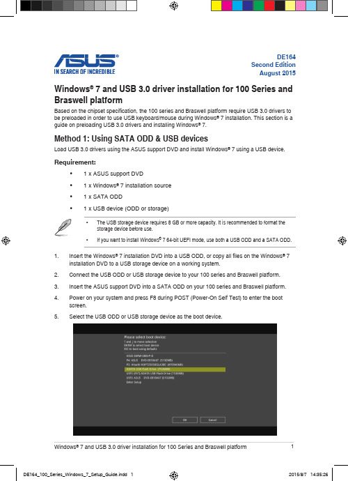
The “Setup is starting...” screen will show up if the USB 3.0 driver is loaded correctly.Follow the onscreen instructions to complete the Windows® 7 installation. Method 2: Using a modified Windows® 7 ISOLoad USB 3.0 drivers and install Windows® 7 using a modified Windows® 7 installation DVD. Requirement:• 1 x ASUS support DVD• 1 x Windows® 7 installation source• 1 x Working system (PC or notebook)- Select the USB storage device and click next.Click the refresh icon if the USB storage device is not displayed.- C lick Yes to clear the contents on the USB storage device and create a bootable USB device.Make sure to backup contents on the USB storage device, as it will be formatted.- Once completed, click OK to finish.- Check I agree and then click Next.- Once completed, click OK to finish.- Burn this ISO file onto an empty DVD to create a modified Windows® 7 installation DVD.Insert the modified Windows® 7 installation DVD into an ODD or connect the USB storage device with modified Windows® 7 installation files onto your 100 series and Braswell platform.Power on your system and press F8 during POST (Power-On Self Test) to enter the boot screen.Select the ODD or USB storage device as the boot device.The USB 3.0 driver will be loaded automatically during installation startup.。
USB驱动安装介绍

USB driver installation User guideU S BDr i v e r I n s t a l l a t i o n1. When the connection of USB Data Communication with the port succeeds, you will seethe message ‘Found New Hardware’ and ‘Found New Hardware Wizard’ will be displayed on the screen.2. As in the figure above, select ‘no, not this time’ and click ‘Next’.3. Select ‘Install from a list or specific location (Advanced)’ and click ‘Next’.▶ The route for ‘Search for the best driver in these locations’4. As in the figure above, check ‘Include this location in the search’ and click ‘Browse’.5. When ‘Browse For Folder’ is displayed, select the folder which the driver file is located inand click ‘OK’. After that, click ‘Next’ on the ‘Found New Hardware Wizard’.The driver file location : Local Disk(C:) → Program Files → M2I Corp → XDesignerPlus→ usb_driver)6. As in the figure above, searching the driver file is done, click ‘Next’.7. During the progress, a caution will be displayed, as in the figure above. Click ‘ContinueAnyway’.8. As the installation proceeds, a status progress bar displays.9. Click ‘Finish’ to close the wizard.The route for ‘Don’t search. I will choose the driver to install’▶10. As in the figure above, select ‘Don’t search. I will choose the driver to install’ and click‘Next’.12. When ‘Install From Disk’ is displayed, click ‘browse’.13. Select the folder which the driver file is located in and select the file and click ‘Open’. The driver file location : Local Disk(C:) → Program Files → M2I Corp → XDesignerPlus → usb_driver).14. When ‘M2I Corporation USB Driver’ is displayed, select the driver and click ‘next’.15 During the progress, a caution will be displayed, as in the figure above. Click ‘ContinueAnyway’.16 As the installation proceeds, a status progress bar displays.17 Click ‘Finish’ to close the wizard.Execute ‘Device manager’ to check the driver has been installed successfully.18. Click ‘Start’ →‘Control Panel’ or ‘Start’→‘Option’→‘Control Panel’19. Double click ‘System’20. When ‘System Properties’ displays, click ‘Hardware’ tab and click ‘Device manager’.21. As in the figure above, if ‘M2I Corporation USB Driver’ displays under ‘Universal SerialBus controller’, the driver has been installed successfully.※‘M2I Corporation USB Driver’ is displayed, only when the USB cable is connected.22. As in the figure above, if displays beside ‘USB Device’ or ‘M2I Corporation USB Driver’,try reconnecting the USB cable to the port or install the driver again by ‘Update Driver…’.。
戴尔适配器 - USB 3.0 至 HDMI VGA 以太网 USB 2.0 用户指南说明书

User Guide Model: DA100NOTE: A NOTE indicates important information that helps you makebetter use of your computer.CAUTION: A CAUTION indicates potential damage to hardware or lossof data if instructions are not followed.WARNING: A WARNING indicates a potential for property damage,personal injury, or death.© 2014 Dell Inc. All rights reserved.Information in this document is subject to change without notice. Reproduction of these materials in any manner whatsoever without the written permission of Dell Inc. is strictly forbidden.Trademarks used in this text: Dell and the Dell logo are trademarks of Dell Inc., Intel®, Centrino®, Core™, and Atom™ are either trademarks or registered trademarks of Intel Corporation in the U.S. and other countries; Microsoft®, Windows®, and Windows start button logo are either trademarks or registered trademarks of Microsoft Corporation in the United States and/or other countries; Bluetooth® is a registered trademark owned by Bluetooth SIG, Inc. and is used by Dell under license; Blu-ray Disc™ is a trademark owned by the Blu-ray Disc Association (BDA) and licensed for use on discs and players; Other trademarks and trade names may be used in this document to refer to either the entities claiming the marks and names or their products. Dell Inc. disclaims any proprietary interest in trademarks and trade names other than its own.2015 – 07 Rev. A01aSpecificationsUpstream Input• USB 3.0Downstream Outputs • USB 2.0• HDMI• VGARecommended System RequirementsHardware•Dual Core Intel CPU 2 GHz or better•USB 3.0 output portOperating System•Windows OS (Win 7, 8, 8.1, 10) 32/64 bitsOperating TemperatureMax. operating temperature is 40o C53. Click "I Accept". DisplayLink Core software and DisplayLink Graphics will be installed.4. Connect your Adapter and peripherals to your PC.* Adapter supports a single video output capability with the choice of two ports: 1 x HDMI or 1 x VGASS8Fit to TV configuration1. To configure Fit to TV, choose the option from the DisplayLink GUI.The following interface appears2. You will also see a red border on the DisplayLink screenThe red border shows the size of the new Windows desktop. Use the “+” and “-” controls on the Fit to TV GUI tochange the size of the red border until it fits on the TV screen.Note: Finer configuration of the size of the border can be achieved by holding down the CTRL key and clicking the “+” and “-”.3. Once the red border is at the edges of the TV screen, click “Apply” to resize theWindows desktop.Troubleshooting guide for Dell 4-1 Adapter (DA100)9Regulatory InformationDell 4-1 Adapter (DA100) complies with the FCC/CE rules and abides by worldwide regulatory compliance, engineering, and environmental a airs.Contacting Dell:1. Visit /support2. Select your support category3. Select the appropriate service or support link based on your need.Or Visit:/support/.10。
ESI MAYA22 USB 24位USB音频接口用户指南说明书

Flexible High Performance 24-bit USB Audio InterfaceUser’s GuideESI - Copyright © 2013 Revision 1, November 2013INDEX1. Introduction (4)1.1 Features (4)2. Installation (5)2.1 System Recommendation (5)2.2 Hardware Installation (5)2.3 Driver & Software Installation (5)2.3.1 Installation under Windows XP (6)2.3.2 Installation under Windows Vista / 7 / 8 (7)2.3.3 Installation under Mac OS X (8)3. Control Panel under Windows (9)3.1 Input Selection (9)3.2 Input Monitoring (9)3.3 Latency settings (10)3.3 DirectWIRE (10)4. Control Panel under Mac OS X (11)4.1 Input Selection (12)4.2 Input Monitoring (12)5. Specifications (13)6. General Information (14)1. IntroductionMAYA22 USB is not simply another USB audio interface - it's a very stylish portable device that can go with you anywhere. It offers total flexibility as an external and fully bus-powered USB device with excellent professional 24-bit audio quality.It features 2 analog input and 2 analog output channels with RCA connection, a microphone preamplifier with XLR input and support for +48V phantom power, a Hi-Z instrument input for guitars, a high quality headphone output and TRS line outputs. This can make MAYA22 USB easily one of the most useful devices in your studio, wherever that may be.Use it to record microphone and guitar signals simultaneously and then process the incoming signals with your PC or Mac notebook or desktop in realtime and listen to the mix directly via headphones or studio monitoring speakers. All these features are provided with a professional low latency drivers with support for WDM, ASIO 2.0 and CoreAudio.If you're looking for a really powerful USB audio device that is small and that gives you maximum performance under any current Windows system as well as under Mac OS X, then MAYA22 USB is for you. It's incredible how many functions are provided by this small device!1.1 FeaturesThe MAYA22 USB hardware has these main features:1. USB connection port (connects to your computer with the supplied cable)2. Line Output with balanced 1/4" TRS connection3. XLR and TRS microphone input4. input signal indicator LED5. +48V phantom power switch (for condenser microphones)6. Hi-Z instrument input with 1/4" connector7. Line Input with RCA connectors8. Stereo Headphone Output with 1/4" connectionThe cool compact design allows you to take MAYA22 USB with you, wherever you go. As companion to a notebook computer, you can take your recording projects with you. MAYA22 USB is simple to install and even easier to use. Working with recording software has never been easier, with the help from MAYA22 USB.2. Installation2.1 System RecommendationMAYA22 USB is not simply a standard digital audio interface, but a high-resolution device capable of advanced processing of audio content. Even though MAYA22 USB is built to have low-CPU resource dependability, system specifications play a key part in the MAYA22 USBs performance. Systems with more advanced components are generally recommended.Minimum System RequirementsPC- Intel Pentium III 600MHz CPU or comparable AMD CPU (or equivalent)- Windows XP or Windows Vista / 7 / 8 (32- and 64-bit) operating system- 1 available USB port- at least 2 GB RAM- high quality audio software with ASIO support recommendedMac- Macintosh with Intel CPU- 1 available USB port- at least 2 GB RAM- Mac OS X 10.4 or higher2.2 Hardware InstallationMAYA22 USB is simply connected to an available USB port of your computer. A separate power supply is not required, as MAYA22 USB is a USB powered device. Simply install the hardware by plugging it into your computer with the supplied cable.USB port of a computer2.3 Driver & Software InstallationAfter the connection of MAYA22 USB, the operating system automatically detects it as a new hardware device. Modern operating systems like Windows XP, Windows Vista/7/8 or Mac OS X usually detect the hardware directly and are installing the correct USB audio drivers automatically. You can use MAYA22 USB already now in typical consumer audio applications that do not need special professional ASIO driver support. Under Windows XP this could be for example programsused for DVD playback or more simple DJ applications that don’t require ASIO. Under Mac OS X this could be applications like Garageband.2.3.1 Installation under Windows XPUnplug the device before you start the installer if it is already connected. Then launch setup.exe from the Windows folder of the included driver CD or from a download of a recent driver from our website.You will now see a dialog as shown on the left picture below. Click Next. You can define the target directory for the installation now. Confirm it with Next.The installer now informs you that the driver installation will start as shown on the left picture below. Confirm this with Next. During the following process you will see a dialog box once or several times that informs you that the driver software has not passed Windows Logo testing. Please be assured that our drivers have been tested in various different ways and are OK to be used. Confirm any such dialog with Continue Anyway.You will now be prompted to connect the hardware on the next dialog that is shown below on the left. Plug in MAYA22 USB. Do not click Next yet. During the driver installation, Windows might again prompt you to confirm the Windows Logo testing dialog once or several times with Continue Anway before the driver installation is finalised.You can now finally click Next on the ESI MAYA22 USB Audio Driver Setup dialog. The installation is now finished. To confirm this, please check if the ESI icon is displayed in the taskbar notification area as shown below. Sometimes a reboot is required.If yes, the driver installation has been completed successfully.2.3.2 Installation under Windows Vista / 7 / 8Unplug the device before you start the installer if it is already connected. Then launch setup.exe from the Windows folder of the included driver CD or from a download of a recent driver from our website.When launching the installation, Windows Vista / 7 / 8 might prompt a security message. Make sure to allow the installation. You will then see a dialog as shown on the left picture below. Click Next. You can define the target directory for the installation now. Confirm it with Next.The installer now informs you that the driver installation will start as shown on the left picture below. Confirm this with Next. During the following process you might see a Windows Security dialog box once or several times that asks you for confirmation to install the driver software. Confirm any such dialog with Install.You will now be prompted to connect the hardware on the next dialog that is shown below on the left. Plug in MAYA22 USB. Do not click Next yet. Instead, wait a few seconds for the automatic device driver installation. You can monitor this in the task notification area where Windows Vista / 7 informs that the driver is installed via a bubble message box.You can now finally click Next on the ESI MAYA22 USB Audio Driver Setup dialog. The installation is now finished. To confirm this, please check if the ESI icon is displayed in the taskbar notification area as shown below. Sometimes a reboot is required.If yes, the driver installation has been completed successfully.2.3.3 Installation under Mac OS XMac OS X already provides support for class compliant USB audio devices such as MAYA22 USB. This means that no software or driver needs to be installed to use MAYA22 USB under Mac OS X. Simply connect the unit with the supplied USB cable to your Mac and you can start using it.To make the usage more simple, we provide a control panel application that can be installed from the included CD (Mac OS X folder) or downloaded on our website. To install it, open the .dmg file and then launch the installer by double clicking the contained .pkg package file. Follow the instructions on screen to install it.Controlling some of the basic options of MAYA22 USB under Mac OS X can also be done via the Audio MIDI Setup utility from Mac OS X.3. Control Panel under WindowsThis chapter describes the MAYA22 USB Control Panel under Windows.To open the control panel double click on the ESI icon in the task notificationarea. The following dialog will appear:The panel has the following functions and sections:INPUT section: this section controls the input monitoring volume of the incoming signal from the hardware. A pair of mono faders can be controlled together or individually depending on your mouse position – perfect for stereo signals. The Mute button the channel allows you to mute the signal. A red Mute button indicates that the mute function is enabled. When disabled, the button is gray.OUTPUT section: this section controls the playback volume of the playback signal from your audio applications. The pair of mono faders can be controlled together or individually depending on your mouse position – perfect for stereo signals. The Mute button the channel allows you to mute playback. A red Mute button indicates that the mute function is enabled. When disabled, the button is gray.3.1 Input SelectionWith the buttons on the left side, you can select the line input (Line In), the microphone input (Mic), the instrument input (Hi-Z) or simultaneous recording of microphone and instrument signals (Mic Hi.Z) via the corresponding button. When Mic Hi-Z is selected, the microphone input signal will be recorded on the left input channel 1 and the instrument signal on the right input channel 2.3.2 Input MonitoringThe Mon button (located between INPUT and OUTPUT) allows you to enable realtime input monitoring. Once enabled all incoming signals are audible through the output. You can control the input monitor level, the input level and the output level with the faders in the control panel.3.3 Latency settingsVia Config > Latency in the Control Panel it is possible to change the latency setting (also called “buffer size”) for the driver of MAYA22 USB. A smaller latency is the result of a smaller buffer size. Depending on the typical application (e.g. for playback of software synthesizers) a smaller latency is an advantage. At the same time, the best latency setting indirectly depends on the performance of your system. For recording applications, a typical latency buffer size between 4 and 8ms is standard. Note that the latency has to be setup before launching the audio application using MAYA22 USB.3.3 DirectWIREWhat is DirectWIRE?DirectWIRE is a driver technology, developed by ESI, which can be used for routing audio streams internally within applications using EWDM Audio MIDI Drivers exclusively developed by ESI.With the DirectWIRE router, an application can record from other application’s audio outputs without external wiring or any loss of data when they are running at the same time.DirectWIRE also allows you to easily rip any audio stream in real time by transferring data thru DirectWIRE from MP3s, live On-line Broadcast and On-demand content, and more.DirectWIRE is not available under Mac OS X.DirectWIRE PanelClick on DirectWIRE on the MAYA22 USB control panel. The DirectWIRE dialog as shown below will appear. DirectWIRE digital virtual wiring technology, developed by ESI, routes audio streams internally within applications using standard audio drivers such as WDM, ASIO and MME, even when they are running at the same time.The number on the row represents the input or output port. The columns represent ins and outs (on and off) of the respected drivers. Patch the virtual cables from one point to another as you drag your mouse point.INPUT section: It's used to route signals from the card's hardware inputs.MME section represents general application's I/O: Ex.) WinAmp, WaveLab (non ASIO mode), Cakewalk, Audition, Vegas, etc.WDM section represents Multi-MME application’s I/O: Ex.) SONAR (when using WDM/KS), PowerDVD, WinDVD, etc.ASIO section represents ASIO application’s I/O: Ex.) Cubase, Logic, Reason, Nuendo, SONAR (when using ASIO), Samplitude, etc.GSIF section represents GSIF application like GigaStudio.Note that some applications support multiple driver modes.DirectWIRE ExamplesExample 1. Recording from WinAmp (MME) to WaveLab (MME).If you want to record what's played back in WinAmp, but don't want to hear the sound, you should click the OUT button in the MME section so it'll change to OFF .Example 2. Recording from WinAmp (MME) toSONAR (WDM). Example 3. Recording from WinAmp (MME) toCubase, Logic, Nuendo (ASIO).Example 4. Recording from GigaStudio (GSIF) toSONAR (WDM). Example 5. Recording from GigaStudio (GSIF) toCubase (ASIO).4. Control Panel under Mac OS XThis chapter describes the MAYA22 USB Control Panel under Mac OS X.After the installation, the panel can be found in your Applications folder. You can launch it in the Finder via Go> Applications > MAYA22 USB Panel. The following dialog appears:The panel has the following functions and sections:INPUT section: this section controls the input monitoring volume of the incoming signal from the hardware. A pair of mono faders can be controlled together or individually depending on your mouse position – perfect for stereo signals. The Mute button the channel allows you to mute the signal. A red Mute button indicates that the mute function is enabled. When disabled, the button is gray.OUTPUT section: this section controls the playback volume of the playback signal from your audio applications. The pair of mono faders can be controlled together or individually depending on your mouse position – perfect for stereo signals. The Mute button the channel allows you to mute playback. A red Mute button indicates that the mute function is enabled. When disabled, the button is gray.4.1 Input SelectionWith the buttons on the left side, you can select the line input (Line In), the microphone input (Mic), the instrument input (Hi-Z) or simultaneous recording of microphone and instrument signals (Mic Hi.Z) via the corresponding button. When Mic Hi-Z is selected, the microphone input signal will be recorded on the left input channel 1 and the instrument signal on the right input channel 2.4.2 Input MonitoringThe Mon button (located between INPUT and OUTPUT) allows you to enable realtime input monitoring. Once enabled all incoming signals are audible through the output. You can control the input monitor level, the input level and the output level with the faders in the control panel.5. SpecificationsProduct Overview:- 2 input / 2 output USB 2.0 24-bit Audio Interface- line, guitar and microphone inputs- simultaneous recording of microphone and guitar signals - microphone preamp with +48V phantom power support- line and headphone outputs- ESI 7012L controller chip- USB bus poweredKey Features:- USB 2.0 Full Speed- 2 input channels- 2 output channels- Input Type:- 1 XLR (for microphone), +48V support- 1 TS unbalanced Hi-Z (for guitar)- 2 RCA unbalanced (for line signals)- Output Type:- 2 TRS balanced (left/right channel line signal)- 1 headphone output (stereo)Audio Specifications:- 24-bit / 96kHz- ADC Dynamic Range:102dBA@48kHz, SNR = 102dBA@48kHz- DAC Dynamic Range:108dBA@48kHz, SNR = 108dBA@48kHzCompatibility:- supports Windows XP, Windows Vista, Windows 7 andWindows 8 with ASIO 2.0, MME, WDM and DirectSoundincl. DirectWIRE support and realtime level meters inMAYA22 USB for Windows control panel software- supports Mac OS X (10.4 and above) via the nativeCoreAudio USB audio driver from Apple (no driver install required, MAYA22 USB for Mac control panel available)6. General InformationTrademarksESI, MAYA22 and MAYA22 USB are trademarks of ESI Audiotechnik GmbH. Windows is a trademark of Microsoft Corporation. Other product and brand names are trademarks or registered trademarks of their respective companies.The FCC and CE Regulation WarningThis device complies with Part 15 of the FCC Rules. Operation is subject to the following two conditions : (1) this device may not cause harmful interference, and (2) this device must accept any interference received, including interference that may cause undesired operation. Caution : Any changes or modifications in construction of this device with are not expressly approved by the party responsible for compliance, could void the user's authority to operate equipment.Note: This equipment has been tested and found to comply with the limits for a Class A digital device, pursuant to Part 15 of the FCC Rules. These limits are designed to provide reasonable protection against harmful interference when the equipment is operated in a commercial environment. This equipment generates, uses, and can radiate radio frequency energy and, if not installed and used in accordance with the instruction manual, may cause harmful interference to radio communications. Operation of this equipment in a residential area is likely to cause harmful interference in which case the user will be required to correct the interference at his own expense. If necessary, consult an experienced radio/television technician for additional suggestions. CorrespondenceFor technical support inquiries, contact your nearest dealer, local distributor or ESI support online at . Please also check our extensive Knowledge Base with Frequently Asked Questions, installation videos and technical details about our products in the support section of our website.DisclaimerAll features and specifications subject to change without notice.Parts of this manual are continually being updated. Please check our web site occasionally for the most recent update information.。
8-Bit USB Debug Adapter 用户指南说明书

Rev. 0.3 1/15Copyright © 2015 by Silicon Laboratories8-Bit USB Debug AdapterIT EBUG DAPTER SER S UIDE1. IntroductionThe 8-bit USB Debug Adapter (UDA) provides the interface between the PC’s USB port and the Silicon Labs 8-bit target device’s in-system debug/programming circuitry. The 10-pin ribbon cable connects the adapter to the target board and the target device’s debug interface.Figure1.8-Bit USB Debug AdapterVisit /8bit-uda for ordering information.2. Relevant DocumentationApplication notes can be found on the 8-bit MCU Application Notes web page: /appnotes .⏹ AN124: Pin Sharing Techniques for the C2 Interface —Describes in detail the debug interface pinsharing feature for C2 devices, which enables debugging and use of the /RST and GPIO pins shared with C2CK and C2D.⏹ AN117: Using C8051Fxxx On-Chip Interface Utilities DLL —The SiUtil DLL discussed in this document uses the USB Debug Adapter to program the memory space of C2 and JTAG devices.⏹ AN134: Multiple-Device JTAG Configuration in the Silicon Labs IDE —Configuration in the IDE and using the USB Debug Adapter for devices in a JTAG chain.8-Bit USB Debug Adapter3. Pinout SpecificationThe 8-Bit USB Debug Adapter supports both Silicon Laboratories JTAG and C2 debug interfaces, and the adapter is powered from the USB connection to the PC. The UDA is also capable of providing power to the target device or other circuitry via pin 10 of the connector. Table1 shows the pin definitions for the UDA keyed connector. The part number for the matching shrouded and keyed connector for a PCB is 2510-6002UB from 3M.The USB Debug Adapter can automatically change the communication voltage level based on the level detected on pin 7 of the connector. As a result, this pin should be pulled high with a strong pull-up (~1kΩ) for noise immunity purposes and not pulled down to ground.Notes:•The USB Debug Adapter requires a target system clock of 32kHz or greater.•With the default settings, the USB Debug Adapter can supply up to 100 mA to a target system.Table 1. USB Debug Adapter Debug Connector Pin DescriptionsPin #Description Details1Not Connected2GND (Ground)3GND (Ground)4TCK / C2D JTAG TCK or C2 Data5TMS / C2CK pin share JTAG TMS or C2 Clock pin sharing6TDO / C2D pin share JTAG TDO or C2 Data pin sharing7TDI / C2CK JTAG TDI or C2 Clock signalThis pin is used by the UDA to sense and setthe logic voltage level. This pin should neverhave a pull-down to ground.8Not Connected9GND (Ground)10USB Power 5 V power from the UDA8-Bit USB Debug Adapter4. Minimum C2 Programming ConnectionsThe minimum required programming connections for the C2 interface are C2D (pin 4), C2CK (pin 7), and ground (pins 2, 3, or 9).5. Hardware Setup using a USB Debug AdapterConnect a target board to a PC running the Silicon Laboratories IDE via the USB Debug Adapter as shown in Figure 3.1. Connect the USB Debug Adapter’s 10-pin ribbon cable to the JTAG or Debug connector on the target board.2. Connect one end of a standard USB cable to the USB connector on the USB Debug Adapter.3. Connect the other end of the USB cable to a USB Port on the PC.4. Power the target board.Notes:•Use the Reset button in the IDE to reset the target when connected using a USB Debug Adapter.•Remove power from the target board and the USB Debug Adapter before connecting or disconnecting the ribbon cable from the target board. Connecting or disconnecting the cable when the devices have power can damage the device and/or the USB Debug Adapter.Figure 3.Hardware Setup using a USB Debug Adapter6. USB DriversThe USB Debug Adapter uses the Human Interface Device (HID) USB interface to communicate with the PC.Since most operating systems have this driver automatically built in, no drivers need to be installed to use the UDA.1238-Bit USB Debug Adapter7. Software Setup using a USB Debug AdapterThe Silicon Laboratories Integrated Development Environment (IDE) along with other software tools are provided for device development and debugging. The IDE is available for download from the Silicon Laboratories website (/mcudownloads ) and is also available on microcontroller development kit CD-ROMs.7.1. Configuring the USB Debug Adapter in the Silicon Labs IDEOnce the IDE has been installed and the hardware has been connected as shown in Section 5, follow the steps below to built a project, connect and download to a target board using the USB Debug Adapter.1. Select Project →Open Project... to open a previously saved project.2. Before connecting to the target device, several connection options may need to be set. Open the Connection Options window (shown in Figure 4) by selecting Options →Connection Options... in the IDE menu.3. Select USB Debug Adapter in the Serial Adapter section.4. If more than one adapter is connected, choose the appropriate serial number from the drop-down list.5. Check the Power target after disconnect option if the target board is currently being powered by the USB Debug Adapter. The board will remain powered after a software disconnect by the IDE.6. Next, the correct Debug Interface must be selected. Check the Debug Interface corresponding to the Silicon Laboratories device on the target board.7. Once all the selections are made, click the OK button to close the window.8. Click the Connect button in the toolbar or select Debug →Connect from the menu to connect to thedevice. 9. Download the project to the target by clicking the Download Code button in the toolbar.10. Save the project when finished with the debug sessionto preserve the current target build configuration, editor settings and the location of all open debug views. To save the project, select Project →Save Project As... from the menu. Create a new name for the project and click on Save .Figure 4.Connection Options8-Bit USB Debug Adapter 8. SchematicsDisclaimerSilicon Laboratories intends to provide customers with the latest, accurate, and in-depth documentation of all peripherals and modules available for system and software implementers using or intending to use the Silicon Laboratories products. Characterization data, available modules and peripherals, memory sizes and memory addresses refer to each specific device, and "Typical" parameters provided can and do vary in different applications. Application examples described herein are for illustrative purposes only. Silicon Laboratories reserves the right to make changes without further notice and limitation to product information, specifications, and descriptions herein, and does not give warranties as to the accuracy or completeness of the included information. Silicon Laboratories shall have no liability for the consequences of use of the information supplied herein. This document does not imply or express copyright licenses granted hereunder to design or fabricate any integrated circuits. The products must not be used within any Life Support System without the specific written consent of Silicon Laboratories. A "Life Support System" is any product or system intended to support or sustain life and/or health, which, if it fails, can be reasonably expected to result in significant personal injury or death. Silicon Laboratories products are generally not intended for military applications. Silicon Laboratories products shall under no circumstances be used in weapons of mass destruction including (but not limited to) nuclear, biological or chemical weapons, or missiles capable of delivering such weapons.Trademark InformationSilicon Laboratories Inc., Silicon Laboratories, Silicon Labs, SiLabs and the Silicon Labs logo, CMEMS®, EFM, EFM32, EFR, Energy Micro, Energy Micro logo and combinations thereof, "the world’s most energy friendly microcontrollers", Ember®, EZLink®, EZMac®, EZRadio®, EZRadioPRO®, DSPLL®, ISOmodem ®, Precision32®, ProSLIC®, SiPHY®, USBXpress® and others are trademarks or registered trademarks of Silicon Laboratories Inc. ARM, CORTEX, Cortex-M3 and THUMB are trademarks or registered trademarks of ARM Holdings. Keil is a registered trademark of ARM Limited. All other products or brand names mentioned herein are trademarks of their respective holders.Silicon Laboratories Inc.400 West Cesar Chavez Austin, TX 78701USAIoT Portfolio /IoTSW/HW/simplicityQuality/qualitySupport and Community。
惠联DHS-09M USB声卡适配器用户手册说明书

DIGITAL USB ADAPTER(DSU-09M) TO HEADSETThank you for choosing Digital USB to headset sound card adapter. Use the adapter cord to adapt any headsets to any PC via the USB port on your PC.This User guide will help you in setting your new headset and adapter cord to your computer, using and maintaining the USB adapter, and all the necessary information required to receive the full benefits from USB adapterThis user guide contains the following sections ;1. Operating System2. Features3. Installation4. Operation5. General USB troubleshooting in Windows 98 SE and WindowsME.1. Operating System1) Windows XP, Windows 7, Windows 82) Windows 2000,VISTA3) Windows ME (Millennium Edition)4) Windows 98 Second Edition5) Software : None requiredVolume Down Hook On/Off Volume Up TX Mute DH-035TB2. Features1) USB plug & play chip2) Complete Digital sound card3) Clear live voice transmission with VoIP4) Digital in-line receive volume control5) In-line microphone (Tx) MUTE with LED indicator6) Hook On/Off with LED indicator7) Headset rapid release connector8) ON/OFF Control button with VoIP software(MS-Lync)3. InstallationConnecting the USB adapter to your computer’s USB port is a simple and complete plug & play process. The installation is completed.*NOTE : Installing software by CDROM is not required.4. Operation1) In-line microphone mute button :When you push the microphone mute button while recording, dictating or speaking live, the other party will no longer hear your voice.2) In-line receive volume control : Adjust the digital receive volume control up or down as to your personal preference.5. General USB troubleshooting in Windows 98Second Edition and Windows ME.The information in this article applies to :*Microsoft Windows Millennium Edition*Microsoft Windows 98 Second EditionBecause USB device are plug and play devices, there is little that you can do to control or configure them. However, you can trace most USB problems to one of the following conditions :*Malfunctioning or incorrectly configured hardware*Malfunctioning, incorrectly configured, or missing device driver*Out-of-date firmware or basic input/output system (BIOS)You can use the following troubleshooting tips to check for each of these conditions to help you resolve USB device issues.Malfunctioning or Incorrectly Configured HardwareTypically, if you plug a malfunctioning or incorrectly-configured device into a USB port, it causes the computer to stop responding(hang). In the majority of these instances, you must physically turn off the computer and turn it back on to reset the bus. Note that it may be more difficult to identify which device is malfunctioning or is incorrectly configured. If another computer that you know is working correctly is available, try to plug the device into that computer to see if you encounter the same issue. If the device is plugged into a secondary hub, unplug the device from the hub and then plug the device directly into the root hub.Many hardware problems (such as high or low power, bandwidth shortage, malfunctioning or incorrectly configured firmware, and so on) can cause issues to occur.Malfunctioning, Incorrectly configured, or Missing device driver When you plug in a USB device, the computer should load and then configure the device without ever requesting a device driver (assuming that the device falls within the defined and supplied class drivers). If the computer prompts you for a device driver, check with the manufacturer of the device to determine if a driver is available.Mismatched cablingThere are two types of USB cables, high speed and low speed. Low- speed cables differ from high-speed cable primarily in their shielding. If you plug a high-speed device into a low-speed cable, you can cause signal distortion over long distances.Verify the entire USB chain is working correctly to be certain that a device that requires the ability to draw power from the hub is not plugged into the chain on the other side of a non-powered hub. This causes than hub and all of the devices down the chain to be suspended. If the hub is a powered hub, verify that the power supply for that hub is configured properly.Out-of-date firmware or BIOSThe key to all USB devices is the firmware. The USB device’s firmware contains all of the information about the device. A port is not reset until all of the descriptors in the firmware have been loaded and verified by the root hub. This is critical because it applies to items such as printers and modems. Make certain that you have the most up-to-date firmware that is available for both your computer’s BIOS and each individual device.The symptoms of malfunction or incorrectly configured firmware might be unusual. Typically, when you remove and then re-add a USB device, the device simply becomes available again. However, the device may appear as a second instance of a device, and load itself as such in Device manager. If you see duplicates of a device, verify that you have the most up-to-date firmware for that device. A similar issue that has the same cause occurs when a device loads a device driver and then adds a second device for which there appears to be no driver. The second device is displayed with an exclamation point in a yellow circle in device manager. The device may work correctly, but you cannot remove the “ghost”device until you unplug the parent device that seems to have generated the ghost device. Also, you may be able to resolve this issue by updating the firmware or the device driver for that device.6. Adjusting the Speaker Volume and MicrophoneLevels.Test that the speaker volume in your headset is working and set at a comfortable level by adjusting the RX volume buttons(Volume up for +, Volume down for -).The audio tab in the Properties window also lets you adjust the Sound Recording or microphone levels. The Volume slider adjusts the sound recording or microphone levels. Make sure that the volume slider is set in the middle of the control and the Mute box is not checked.* Theses controls adjust the volume, however, many other applications contain their own volume controls. These independent applications may override the Windows controls and work independent of the USB Adapter sound controls.。
USB接口的RF模块用户指南说明书

CUSTOMER’S CODE RF-Module-USB-Adapter PANASONIC’S CODEPANxxxxDATE11.09.2012TABLE OF CONTENTS1.Scope of this Document (2)2.Description for the Module (2)2.1.Schematic (3)2.2.Description of the USB-Adapter (4)2.3.Connection of the Wireless Moduls (5)3.Software Handling (5)3.1.Device Drivers (5)4.RoHS Declaration (6)5.History for this Document (6)6.Related Documents (6)7.General Information (7)8.Life Support Policy (7)CUSTOMER’S CODE RF-Module-USB-Adapter PANASONIC’S CODEPANxxxxDATE11.09.20121. SCOPE OF THIS DOCUMENTThis User Guide applies to the RF-Module-USB-Adapter which can be used for following Panasonic Modules: PAN2580ETU, PAN4561ETU, PAN4580ETU,PAN7580ETU. The intension is to enable our customers to easily and fast integrate our modules in their product.This guide describes the Hardware and gives usefull hints.2. DESCRIPTION FOR THE MODULEWith the RF Module USB Adapter it is possible to connect following Panasonic ETU-Boards (ETU = EasyToUse) directly with the USB-port of a PC:Customer’s Code Panasonic’s CodePAN2580ETU ENW59635xxxFPAN4561ETU ENWC9A30xxEFPAN4580ETU ENWC9A33xxEFPAN7580ETU ENW59635x3CFPlease contact your local sales office for further details on additional options and services, by visiting /eu/ or write an e-mail to wireless@CUSTOMER’S CODE RF-Module-USB-Adapter PANASONIC’S CODE PANxxxxDATE11.09.20122.1. SCHEMATIC+5V10n F100n F10k+3V 3U S B _A4µ7+3V 3100n F000+5V+3V 34µ7 /n .c .4µ74µ7 /n .c .+3V 3C P 2102270270+3V 3n .c .0270C 3C 1S 1R 3D N 2D P 3G N D @1G N D @2U S B _G N D4U S B _V C C 1X 1G N D @3G N D @4L 1C 2C 4R 7R 8R 9R 10123456789101131211415161718192021222324B Y P A S S6G N D5V _E N 7V _I N 2V _O U T1V _O U T _S E N S E4C 6C 7C 8R E G I N 7VD D6G N D3V B U S 8D +4D -5R S T9S U S P E N D 12S U S P E N D11R I 2D C D 1D T R 28D S R 27T X D 26R X D 25R T S 24C T S 23I C 1G N D E X P G N D M D 1R 4D 2R 6R 1R 2R 5D 3RE S E T U A R T _R X U A R T _T X U A R T _C T SU A R T _R T S V 1.1+Reset Button: Press the button to reset the connected module Converts 5V from USB to 3.3V. Max. output current: 300mA Serial Interface: USB to UART bridgeConnected to pin 3 of the module connector (red, active on high level) D2 Connected to pin 4 of the module connector (red, active on high level) D3 USB-connection (green, active when the USB-connection is OK) Pin Header: Connect the Wireless module to these pin-headerLDO(USB to 3.3V)USB-PlugSerial InterfaceLED D3(USB connection OK)LED D1 and D2(Connected to pin 3 and pin4 of the module)SOFTWARE HANDLINGDEVICE DRIVERSThe USB Interface uses the SINGLE-CHIP USB TO UART BRIDGE CP2102 from Please install the ‘CP210x USB to UART Bridge VCP Drivers’ on your computer toCUSTOMER’S CODE RF-Module-USB-Adapter PANASONIC’S CODEPANxxxxDATE11.09.20124. ROHS DECLARATIONDeclaration of environmental compatibility for supplied products:Hereby we declare to our best present knowledge based on declaration of our suppliers that this product do not contain by now the following substances which are banned by Directive 2002/95/EC (RoHS) or if contain a maximum concentration of 0,1% by weight in homogeneous materials for•Lead and lead compounds•Mercury and mercury compounds•Chromium (VI)•PBB (polybrominated biphenyl) category•PBDE (polybrominated biphenyl ether) categoryAnd a maximum concentration of 0,01% by weight in homogeneous materials for•Cadmium and cadmium compounds5. HISTORY FOR THIS DOCUMENTRevision Date Modification / Remarks0.10 11.05.2012 1st preliminary version.6. RELATED DOCUMENTSFor an update, please search in the suitable homepage.[1] Silabs CP2101 Datasheet/Support%20Documents/TechnicalDocs/cp2102.pdf[2] The latest driver for Silabs CP2102/products/mcu/Pages/USBtoUARTBridgeVCPDrivers.aspxCUSTOMER’S CODE RF-Module-USB-Adapter PANASONIC’S CODEPANxxxxDATE11.09.20127. GENERAL INFORMATION© Panasonic Industrial Devices Europe GmbH 2012.All rights reserved.This product description does not lodge the claim to be complete and free of mistakes. Please contact the related product manager in every case.If we deliver ES samples to the customer, these samples have the status Engineering Samples. This means, the design of this product is not yet concluded. Engineering Samples may be partially or fully functional, and there may be differences to be published Data Sheet.Engineering Samples are not qualified and are not to be used for reliability testing or series production.Disclaimer:Customer acknowledges that samples may deviate from the Data Sheet and may bear defects due to their status of development and the lack of qualification mentioned above. Panasonic rejects any liability or product warranty for Engineering Samples. In particular, Panasonic disclaims liability for damages caused by•the use of the Engineering Sample other than for Evaluation Purposes, particularly the installation or integration in an other product to be sold by Customer, •deviation or lapse in function of Engineering Sample,•improper use of Engineering Samples.Panasonic disclaimes any liability for consequential and incidental damages.In case of any questions, please contact your local sales partner or the related product manager.8. LIFE SUPPORT POLICYThis Panasonic product is not designed for use in life support appliances, devices, or systems where malfunction can reasonably be expected to result in a significant personal injury to the user, or as a critical component in any life support device or system whose failure to perform can be reasonably expected to cause the failure of the life support device or system, or to affect its safety or effectiveness. Panasonic customers using or selling these products for use in such applications do so at their own risk and agree to fully indemnify Panasonic for any damages resulting.。
USB Rover 2850 2-port USB 1.1 40米Cat 5扩展器用户手册说明书
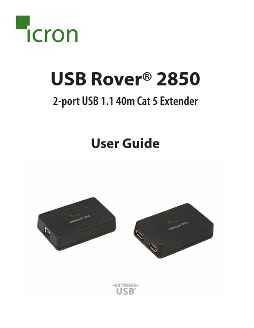
USB Rover® 2850 2-port USB 1.1 40m Cat 5 ExtenderUser GuideThank you for purchasing the USB Rover® 2850,2-port USB 1.1 40 m (131 ft) Cat 5 ExtenderPlease read this guide thoroughly.FCC Radio Frequency Interference Statement WarningThis device complies with FCC Part 15 Subpart B.CE StatementThe product meets European Standard EMC EN 55022 Class B and EN 55024.IC StatementThis Class B digital apparatus complies with Canadian ICES-003.Environmental StatementThis product is RoHS compliant and conforms to the requirements of Directive 2002/95/EC. Saftey StatementsThis product conforms to the standards set out by the CPSIA.This product has a flammability rating of V-1.ContentsIntroduction (4)Product Contents (4)Requirements (4)About the USB Rover® 2850 (4)Local Extender (LEX) and Remote Extender (REX) Descriptions (5)Installation Guide (6)Installing the LEX (6)Installing the REX (6)Connecting the LEX to the REX (7)Connecting a USB device (7)Troubleshooting (8)Specifications (9)Contacting Technical Support (10)Warranty Information (10)Obtaining Warranty Service (11)Technical Glossary (12)IntroductionThe instructions in this guide assume a general knowledge of computer installation procedures, familiarity with cabling requirements, and some understanding of USB devices.NOTE symbol emphasizes additional information that could be useful.CAUTION symbol indicates important information about an operational requirement.Product ContentsPackaged with:• LEX (Local Extender)• REX (Remote Extender)• 2m (6 ft) USB A-B Cable• Quick Start Guide and Warranty InformationRequirementsTo complete the installation you will require the following items that are not included:• USB compatible computer (host computer) with a USB compliant operating system• USB device(s)• Cat 5 Unshielded Twisted Pair (UTP) cable with two RJ45 connectors (if using surface cabling), or Cat 5 cabling with two information outlets and two Cat 5 patch cords with RJ45 connectors(if using premise cabling)A ll references to Cat 5 cable in this document refer to Cat 5e and represent the minimum cablerequirement.About the USB Rover® 2850The USB Rover® 2850 enables users to extend USB devices up to 40m (131 ft). Extension distances of up to 85 meters may be acheivable with some Low-Speed HID devices, such as keyboards and mice. notenotenoteRemote Extender (REX) DescriptionThe REX provides two downstream USB Type A ports for standard USB devices. Additional devices may be connected by connecting USB hubs.ITEMTYPE DESCRIPTION 1Link Port (RJ45)Accepts RJ45 connector for Cat 5 cabling.2 2 Device Ports (USB Type A)Connects to USB1.1/2.0 device(s).Local Extender (LEX) Description The LEX connects to the host computer using the supplied USB A-B Cable.ITEM TYPEDESCRIPTION 1Link Port (RJ45)Accepts RJ45 connector for Cat 5 cabling.2Device Port (USB Type B)Used to connect the LEX to the host computer.2112Installation GuidePreparing your siteThe maximum extension length is reduced by 13.2m (43.3 ft) for each USB hub added between thehost computer and the end device. Extender systems cannot be daisy chained. An extender system can have only one LEX and one REX.1.Determine where the host computer is to be located and set up the computer.2.Determine where you want to locate the remote USB device(s).3.Ensure the cable run (including patch cables) between the host computer and USB device(s) is no greater than 40m.Installing the LEX1.Place the LEX near the host computer.2. P lug the supplied USB cable into the LEX and into an available USB port on the computer.Installing the REX1.Place the REX near the USB device(s) at the desired remote location.USB 1.1 up to 40m over Cat 5REXLEXConnecting the LEX to the REXSurface Cabling1. Plug one end of the Cat 5 cable into the Link port (RJ45) on the LEX.2. Plug the other end of the Cat 5 cable into the Link port (RJ45) on the REX.Premise Cabling1. Plug one end of a Cat 5 patch cord into the Link port (RJ45) on the LEX.2. Plug the other end of the patch cord into the Cat 5 information outlet near the host computer.3. P lug one end of a second Cat 5 patch cord into the Link port (RJ45) on the REX.4. Plug the other end of the second patch cord into the Cat 5 (RJ45) information outlet near the USBdevice.The information outlets at the LEX and REX must be directly connected to each other with Cat 5cabling. There cannot be a switch or router in between the information outlets.Connecting a USB Device1. On the host computer, install any software required to operate the USB device. If necessary, refer to thedocumentation for the USB device(s).2. Connect the USB device(s) to the device port(s) on the REX.PROBLEM CAUSE SOLUTIONThe USB device does not operate correctly.• The USB device ismalfunctioning.• The computer does notrecognize the USB device.• The application software forthe USB device is not operating.1. Un-install and re-install the driver for the USBdevice.2. Update the driver for the USB device.3. Directly connect the USB device to the Host toverify the USB device operates correctly.The USB deviceis detected as an “Unknown Device” in the operating system.• The host computer or USBdevice may not be capable ofsupporting extreme distances.• The USB device’s timing doesnot conform to the USB 1.1specification.1. Connect the LEX to REX using a short cable.2. Unplug the LEX from the host and wait 15seconds. Then plug the LEX back into the host.The operating system reports that a power surge occurred or that the USB device is using too much power.• The Host is not providingenough power to the Extender.1. Connect the LEX to a different USB port on thehost.2. Connect a self-powered USB hub between theREX and the USB device.TroubleshootingThe following table provides troubleshooting tips. The solutions are arranged in the order in which they should be executed in most situations. If you are unable to resolve the problem after following these instructions,pleasecontactTechnicalSupport(*********************)forfurtherassistance.SpecificationsContacting Technical SupportIf you are experiencing problems not resolved by following the steps listed in the Trouble Shooting section, contact Technical Support(*********************)and provide the following information:• Host computer make and model• Operating system installed (e.g. Windows XP, Mac OS X, Windows 7 etc.)• Part number and serial number for both the LEX and REX• Make and model of all USB device(s) attached to the extender• Description of the installation• Description of the problemWarranty InformationLimited Hardware WarrantyIcron Technologies Corporation warrants that any hardware products accompanying this documentation shall be free from significant defects in material and workmanship for a period of up to three years from the date of purchase. Icron Technologies Corporation’s hardware warranty extends to the Licensee, its customers, and end users.The Warranty does not include repair of failures caused by: misuse, neglect, accident, modification, operation outside of a normal operating environment, failure caused by servicing of the device by non-authorized servicers, or failure caused by a product for which Icron Technologies Corporation is not responsible. Hardware RemediesIcron Technologies Corporation’s entire liability and the Licensee’s exclusive remedy for any breach of warranty shall be, at Icron Technologies Corporation’s option, either (a) return of the price paid, or (b) repair or replacement of hardware, which will be warranted for the remainder of the original warranty period or30 days, whichever is longer. These remedies are void if failure of the hardware has resulted from accident, abuse, or misapplication.Limitation of LiabilityThe hardware warranty set forth in this agreement replaces all other warranties. Icron Technologies Corporation expressly disclaims all other merchantability and fitness for a particular purpose and non-infringement of third-party rights with respect to the hardware.No Icron Technologies Corporation dealer, agent, or employee is authorized to make any modification extension or addition to this warranty. Under no circumstances will Icron Technologies Corporation, its suppliers or licensors be liable for any costs of procurement of substitute products or services, lost profits, loss of information or data, or any other special, indirect, consequential, or incidental damages arising inany way out of the sale of, use of, or inability to use Icron Technologies Corporation products or services, even if Icron Technologies Corporation, its suppliers or licensors have been advised of the possibility of such damages.In no case shall Icron Technologies Corporation, its suppliers and licensors’ liability exceed the actual money paid for the products at issue.Since some jurisdictions do not allow the limitation of implied warranties of liability for incidental, consequential, special or indirect damages, the above limitation may not always apply. The above limitation will not apply in case of personal injury where and to the extent that applicable law requires such liability.Obtaining Warranty ServiceTo obtain warranty service and help us serve you better, please provide the following information with your warranty request:• Host computer make and model• Operating system installed (e.g. Windows XP, Mac OS X, Windows 7 etc.)• Part number and serial number for both the LEX and REX• Make and model of all USB device(s) attached to the extender• Description of the installation• Description of the problemContact Icron Technologies Corporation within the warranty period for a Return Material Authorization (RMA) number. Please note that Icron Technologies Corporation will not accept returns without an RMA number. Ensure the product is packaged appropriately for safe shipment and mark the RMA number on the outside of the package. The package must be sent prepaid to Icron Technologies Corporation. It is highly recommended that the package be insured and shipped via a trackable shipping method. The repaired or replaced item(s) will be returned at Icron Technologies Corporation’s expense no later than thirty days after receipt the defective product.Address the returned product to:RMA CoordinatorIcron Technologies Corporation4664 Lougheed Highway, Suite 221Burnaby, BC CanadaV5C 5T5Contacting SalesEmail:***************Tel: +1 604 638 3920Contacting Technical SupportEmail:*********************Tel: +1 604 638 3920Technical GlossaryCategory 5 (Cat 5) Network CablingCategory 5 cable is commonly also referred to as Cat 5. This cabling is available in either solid or stranded twisted pair copper wire variants and as UTP (Unshielded Twisted Pair) or STP (Shielded Twisted Pair). UTP cables are not surrounded by any shielding making them more susceptible to electromagnetic interference (EMI). STP cables include shielding over each individual pair of copper wires and provides better protection against EMI. Cat 5 has been superseded by Cat 5e cabling which includes improved data integrity to support high-speed communications.USB CablesUSB cables have two distinct connectors. The Type A connector is used to connect the cable from a USB device to the Type A port on a computer or hub. The Type B connector is used to attach the USB cable to a USB device.RJ45The Registered Jack (RJ) physical interface is what connects the network cabling (Cat 5) to the LEX and REX unit. You may use either the T568A (Table 1) or T568B scheme (Table 2) for cable termination as the extender uses all four pairs of the cable. RJ45 connectors are sometimes also referred to as 8P8C connectors.RJ45 Pin Positioning Table 1 - T568A WiringTable 2 - T568B WiringPIN PAIR WIRE CABLE COLOR PIN PAIRWIRECABLE COLOR 131WHITE/GREEN 121WHITE/ORANGE 232GREEN 222ORANGE 321WHITE/ORANGE 331WHITE/GREEN 412BLUE 412BLUE511WHITE/BLUE 511WHITE/BLUE 622ORANGE 632GREEN 741WHITE/BROWN 741WHITE/BROWN 842BROWN842BROWNUSB Type APort USB Type A ConnectorUSB Type B ConnectorUSB Type B PortNotesIcron Technologies Corporation 4664 Lougheed Highway, Suite 221 Burnaby, BC CanadaV5C 5T5Tel: +1 604 638 3920Fax: +1 604 638 3930。
USB设备应用开发套件 для Windows Embedded CE 6.0 用户指南说明书
USB Device Application Kit for WindowsEmbedded CE 6.0User's ManualDigi document reference number: 90000926_A© Digi International Inc. 2008. All Rights Reserved.The Digi logo is a registered trademark of Digi International, Inc.All other trademarks mentioned in this document are the property of their respective owners. Information in this document is subject to change without notice and does not represent a commitment on the part of Digi International.Digi provides this document “as is,” without warranty of any kind, expressed or implied, including, but not limited to, the implied warranties of fitness or merchantability for a particular purpose. Digi may make improvements and/or changes in this manual or in the product(s) and/or the program(s) described in this manual at any time.This product could include technical inaccuracies or typographical errors. Changes are periodically made to the information herein; these changes may be incorporated in new editions of the publication.Digi International Inc.11001 Bren Road EastMinnetonka, MN 55343 (USA)+1 877 912-3444 or +1 952 912-34442Contents1Introduction (6)1.1Features (6)2Requirements (7)2.1BSP requirements (7)2.2Microsoft Windows® CE OS Configuration (7)3Installation (9)4Integration (10)4.1Integration overview (10)4.2Integration process (10)4.3Driver starts (12)5Using the USB Device functionality (13)5.1Serial USB Function Client (13)5.2Mass Storage USB Function Client (17)6Uninstallation (18)3USB Device Application Kit for Windows Embedded CE 6.0 - User's Manual4Conventions used in this manualHere is a list of the typographical conventions used in this manual:StyleNew terms and variables in commands, code, and other input. Style In examples, to show the contents of files, the output fromcommands. In, text the C code.Variables to be replaced with actual values are shown in italics.Style For menu items, dialogs, tabs, buttons, and other controls.In examples, to show the text that you enterMenu name > optionA menu followed by one or more options; for example, File >New.This manual also uses these frames and symbols:This is a warning. It helps solve or avoid common mistakes or problems.This is a hint. It contains useful information about a topic.> This is a host computer session> Bold text indicates what must be entered .> This is a target session > Bold text indicates what must be entered .USB Device Application Kit for Windows Embedded CE 6.0 - User's Manual5AbbreviationsASCIIAmerican Standard Code for Information Interchange CPUCentral Processing Unit ESD Electrostatic DischargeGPIO General Purpose Input/Output OS Operating SystemPC PersonalComputer RAMRandom Access Memory ROOTFSRoot File System TFTPTrivial File Transfer Protocol TTY TeletypewriterUSBUniversal Serial BusUSB Device Application Kit for Windows Embedded CE 6.0 - User's Manual1IntroductionThe USB Device Application Kit is a product that brings the USB Device physical interface to your Digi Development board or JumpStart board.The USB Device Application Kit hardware board connects to the Development or JumpStart board via the USB Application Header and the provided 16-pin flat cable. It basically mounts a USBPHY and USB B female connector.The USB Device Application Kit software contains the driver needed to support the USB DeviceController in a Microsoft Windows® Embedded CE 6.0 OS Design.This User's Manual assumes that the reader is able to create, compile and download a kernel image.1.1FeaturesThe following are the main features of the USB Device Application Kit:•USB 2.0 Full Speed (Low speed not supported)•Board is powered from Development or JumpStart board•Operation modes: serial and mass storage,•±15kV ESD protection6USB Device Application Kit for Windows Embedded CE 6.0 - User's Manual2RequirementsHost System requirementsThe development system has to meet the following requirements:•x86 PC with 500 MHz Pentium III or faster processor; 2 GHz Pentium 4 or equivalent recommended•Microsoft Windows® 2000 Professional with Service Pack 4 or Windows XP Professional with Service Pack 1.•Microsoft Windows® CE 6.0 with Service Pack 1 installed and updates•Serial port•Ethernet network card2.1BSP requirementsDisplay interface support recommended for development purposes, but not required.2.2Microsoft Windows® CE OS Configuration2.2.1Required componentsGo to the Catalog and expand Device Drivers > USB Function > USB Function Clients.Then include this element:USB Function Clients:• Mass Storage• serialWhen using ActiveSync the components from Core OS > CEBASE > Applications – EndUser > ActiveSync must be included into the Windows CE project.Then include this element:ActiveSync:• File SyncFurthermore, the component from Core OS > CEBASE > Communication Services andNetworking > Networking – Wide area Network (WAN) must be included into the Windows CE projectThen include this element:Telephony API (TAPI 2.0):•Unimodem Support7USB Device Application Kit for Windows Embedded CE 6.0 - User's Manual2.2.2Recommended catalog componentsOther recommended networking utilities and services are:Core OS > CEBASE > Communication Services and Networking: • Networking Generalo Network Utilities• Serverso FTP Servero Telnet Server8USB Device Application Kit for Windows Embedded CE 6.0 - User's Manual93 InstallationThis release is installed by executing Setup.exe.The installer wizard will guide you in all required steps.After installation has finished, the following components will be on your PC:%ProgramFiles%\Digi\AppKits\USB_Device_AppKit :• Uninstaller : Executable to uninstall this release.• Release Notes and License Agreements.%_WINCEROOT%\OTHERS\Digi\AppKits\USBFN\src\driver:• Sources of the driver.%ProgramFiles% is an environment variable of your system that provides the path to your Program Files directory (usually C:\Program Files)%_WINCEROOT% is an environment variable of your system that provides thepath to your Microsoft Windows® CE root directory (usually C:\WINCE600).USB Device Application Kit for Windows Embedded CE 6.0 - User's Manual4Integration4.1Integration overviewThe USB Device Application Kit integration described in this chapter assumes that you havealready performed the following steps. These steps are fairly general as they are highly dependant on the customer BSP and the Microsoft Windows® CE version used:Before completing these steps, you will need to have the following applications already installed: •Windows Embedded as described in Chapter 2, and• a BSP corresponding with the hardware that will be used.4.2Integration processThe source code of the driver is also available and can be integrated into a Windows Embedded CE6.0 project as a subproject of it.After you have completely built your Project,it’s time to add a new subproject for theUSB_Device_AppKit Module.Open the Solution Explorer and right-click over the Subprojects. Choose Add ExistingSubproject:Navigate to %_WINCEROOT%\OTHERS\Digi\AppKits\USBFN\src\driver directory and select USBFN.pbpxml:10Now you can see the parameter files and the source files.Right click over USBFN and select Rebuild and then right click over the project and select Make Run-Time Image.The driver build should be rebuilt and included in the final nk.bin image, together with the necessary registry entries.4.3Driver startsVerify that the ns9360_usbfn.dll is inside the new image and that the correct registry entries are placed in the final registry file (reginit.ini).Once the project has been built, download it to the target device and start it up.If you have the USB Device Application Kit connected to the peripheral application header of the target, it should be automatically detected, and you should see a console message similar to thefollowing:[UfnPdd_Init]: Loading USB Device Driver… OK.More information may be shown depending on the debug level established in thedriver.In the console an error message will show up telling that an IOCTL isn’tsupported by the driver. That message can be ignored because that IOCTL onlyreceives some interface information that are not important to the functionality ofthe driver5Using the USB Device functionalityThe USB Device driver provides the functionality upon which the USB function client driverswork. The USB function client drivers implement one or more "functions", each providing adifferent capability to the USB host. In this document we'll see two of these function client drivers: •Serial USB Function Client•Mass Storage USB Function Client5.1Serial USB Function ClientFor both serial profiles standard serial support is necessary within the Windows CE image. Thatcomponent can be found at Core OS > CEBASE > Core OS Services > Serial PortSupport.5.1.1Selecting the ActiveSync profileMake the following change in your USBFN.reg file, you need to uncomment the Serial_Class and comment the rest (“;”).[HKEY_LOCAL_MACHINE\Drivers\USB\FunctionDrivers];"DefaultClientDriver"="Mass_Storage_Class""DefaultClientDriver"="Serial_Class";"DefaultClientDriver"="USBSER_Class"Now you can build the project with the profile selected.Right click over USB_Device_AppKit and select Rebuild and then right click over the project and select Make Run-Time Image.5.1.2Using the profile for ActiveSyncOn the PC side (Host) ActiveSync 4.x or higher must have been installed previously.To use ActiveSync some additional components are necessary. Refer to chapter2.2.1 and include the listed components.If the components have been includedafter building the project a SYSGEN must be done again.After building and deploying successfully the Windows CE image a ActiveSync connection might be necessary to be created on the target side. This is only necessary if more than one serial port is enabled on the target device.Following the steps that are necessary to create on the target side a new direct connection that can be used later by ActiveSync.From the Start menu select Settings -> Network and Dial-up Connections and create a new Direct Connection selecting the Make New Connection option. Select on the next page the serial port that was setup by the system for the USB function interface and close the dialog. The information on the following picture is only an example and that value might be different on other platforms.Now the new connection to use the USB function driver is created. The next step is to use that connection as the default configuration for ActiveSync. Select from the Start menu Settings -> Control Panel and open the PC connection item.Click on the Change button and select the new created direct connection from the list of available connections. Confirm both dialogs with OK and now when connecting the USB function device to the PC ActiveSync should automatically start.5.1.3Selecting the Serial profileMake the following change in your USBFN.reg file, you need to uncomment the Serial_Class and comment the rest (“;”).[HKEY_LOCAL_MACHINE\Drivers\USB\FunctionDrivers];"DefaultClientDriver"="Mass_Storage_Class";"DefaultClientDriver"="Serial_Class""DefaultClientDriver"="USBSER_Class"Now you can build the project with the profile selected.Right click over USB_Device_AppKit and select Rebuild and then right click over the project and select Make Run-Time Image.5.1.4Using the Serial profileWhen using the serial profile no additional components are necessary to expose a serial port to the Host.On the PC side (Host) the standard USB serial driver (usbser.sys) need to be installed. Afterbuilding and deploying successfully the Windows CE image connect the USB cable with the device connector to the target and with the host connector to a PC or Laptop. The first time the host willinstall the corresponding driver and the device will be available for use. In the Device Manager the COM number assigned to the serial port can be found and normal serial communication can beused between the target and the connected PC.5.1.5Installing the USB Serial driver under WindowsIn case the USB serial driver isn’t installed on the used Windows machine the usbser.sys file comes with various versions of Windows. It can be found on Windows XP typically inC:\WINDOWS\Driver Cache\i386\driver.cabWhen the generic serial driver is loaded and the USB device connected to the Windows host with a USB cable, Windows should recognize the generic serial device and ask for a driver. IndicateWindows to find the driver in the folder that contains usbser.inf and usbser.sy s.The usbser.inf is included in the Kit as an example and can be found atC:\Program Files\Digi\AppKits\USB_Device_AppKit\infOn Windows XP, when the generic serial device is first plugged in, the "Found New HardwareWizard" starts up. Select "Install from a list or specific location (Advanced)", on the next screen select "Include this location in the search" and enter the path or browse to the folder containingusbser.inf and usbser.sys.Windows will complain that the Generic Serial driver has not passed Windows Logo testing, but select "Continue anyway" and finish the driver installation. In the "Device Manager" (under"Control Panel", "System", "Hardware") on Windows XP expand the "Ports (COM & LPT)" entry and you should see Generic Serial Port listed as the driver for one of the COM ports.5.1.6Uninstalling the USB Serial driver under WindowsTo uninstall the Windows XP driver for Generic Serial Port, right click on the Generic Serial Port entry in the "Device Manager" and select "Uninstall".5.2Mass Storage USB Function Client5.2.1Selecting the profileMake the following change in your USBFN.reg file that is part of the subproject, you need to uncomment the Mass_Storage_Class and comment the rest (“;”).[HKEY_LOCAL_MACHINE\Drivers\USB\FunctionDrivers]"DefaultClientDriver"="Mass_Storage_Class";"DefaultClientDriver"="Serial_Class";"DefaultClientDriver"="USBSER_Class"Now you can build the project with the profile selected.Right click over USB_Device_AppKit and select Rebuild and then right click over the project and select Make Run-Time Image.5.2.2Using the profileTo use the Mass Storage profile a block device like CF, SD card or USB Memory stick is necessary to make the profile working correctly. Following some examples how some of these block devices need to be added to the Windows CE project.Exposing a USB memory stick from the target to a PC (Host) the components USB Mass Storage Function client, USB Host support and USB Storage class driver are necessary. Using any otherWhen connecting the USB cable to the Host it might take some time till thestorage device is represented .6UninstallationThe USB Device Application Kit can be uninstalled separately using Windows Control Panel.Add or Remove Programs:•USB Device Application Kit for Windows Embedded CE 6.0。
M-Audio M-Track Duo USB接口音频接收器用户指南说明书

Box ContentsM-Track DuoUSB-B–to–USB-A Cable Software Download Cards User GuideSafety & Warranty ManualSupportFor the latest information about this product (system requirements, compatibility information, etc.) and product registration, visit .For additional product support, visit /support.macO S users: No driver installation is needed for class-compliant operation with M-Track Duo.iOS users: The power available from an iOS device is not sufficient to power M-Track Duo. Use the Apple Camera Connection Kit (sold separately), a USB break-out cable (sold separately), and a USB power adapter (sold separately) which will provide an additional USB connector to power M-Track Duo.Windows users: Before connecting M-Track Duo to your computer, install the drivers:1.Go to /drivers and download the latest M-Track Duo driver for youroperating system.2.Open the file you downloaded and double-click the driver installer file.3.Follow the on-screen instructions to install the drivers.Software: We've included Pro Tools | F irst M-Audio Edition and MPC Beats with your M-Track Duo so you can get started making music with professional software right out of the box. Register your M-Track Duo on /softwaredownload, and follow the install instructions in your User Account.Virtual Instruments: F ollow the instructions in your user account for installing the included virtual instrument plugins. After installation, most DAWs will not load virtual instrument plugins automatically. In order to access the virtual instrument plugins with Pro Tools | First M-Audio Edition, you will need to choose the plugin folder for the software to scan:Pro Tools | First M-Audio Edition (AAX) plugin folders:Windows (32-bit): C:\Program Files (x86)\Common Files\Avid\Audio\Plug-InsWindows (64-bit): C:\Program Files\Common Files\Avid\Audio\Plug-InsmacOS: Macintosh HD/Library/Application Support/Avid/Audio/Plug-Ins23To set M-Track Duo as your default playback device, follow the directions below based on your computer’s operating system.Windows:1. Use the included USB cable to connect the M-Track Duo to your computer.2. In the Taskbar, locate the Volume Control "speaker" icon. Right-click the speaker andopen Sound Settings > Sounds .Alternatively, go to Start Menu > System > Sound > Sound Control Panel .3. In the Windows Sound control panel select the Playback tab and select USB AudioCodec as the default device. 4. Click the Recording tab and select USB Audio Codec as the default device. 5. Click Properties in the lower right-hand corner.6. In the new window, click the Advanced tab and select 2-channel , 16-bit , 48000 Hz(Studio Quality) as the default format. 7. Uncheck both boxes under Exclusive Mode . 8. Click OK to close the Properties window. 9. Click OK to close the Sound control panel. macOS:1. Use the included USB cable to connect the M-Track Duo to your computer.2. Go to Applications > Utilities > Audio MIDI Setup .3. In the Audio Devices window, select USB Audio Codec in the left column.4. Right-click USB Audio Codec , and select Use this device for sound input .5. Right-click USB Audio Codec , and select Use this device for sound output .6. Quit Audio MIDI Setup.Connection DiagramItems not listed under Introduction > Box Contents are sold separately.Note: Use the +48V (Phantom Power) Switch only if a microphone requires phantom power. Most dynamic microphones and ribbon microphones do not require phantom power, but most condenser microphones do. Consult your microphone's documentation to find out whether it needs phantom power.Front PanelRear PanelMonitorsSetting Up M-Track Duo with Your SoftwareSetting Up M-Track Duo with Pro Tools | First M-Audio Editione the included USB cable to connect the M-Track Duo to your computer.2.Open Pro Tools | First M-Audio Edition.3.Go to Setup > Playback Engine….4.Open the Playback Engine dropdown menu and select USB Audio Codec.Note: You may need to save and restart your project.5.Select your Sample Rate and then click OK to close the Setup window.You can now add tracks to send and receive audio from sources connected to M-Track Duo inputs and stream recorded audio back through the M-Track Duo outputs.Setting Up M-Track Duo with MPC Beatse the included USB cable to connect the M-Track Duo to your computer.2.Open MPC Beats.3.Go to Edit > Preferences….4.For Windows Users: In the Audio window, select ASIO under the Audio Device Typedropdown menu. In the Device dropdown menu, select M-Track Solo and Duo ASIO.For MacO S Users: In the Audio window, select USB Audio Codec under the Output and Input dropdown menus.Note: You may need to save and restart your project.5.Select your Sample Rate and then click OK to close the Preferences window.You can now add tracks to send and receive audio from sources connected to M-Track Duo inputs and stream recorded audio back through the M-Track Duo outputs.45Top Panel1.Input Gain: Adjusts the input's gain level. Set this knob so the corresponding Signal/Clip LEDknob) displays a "healthy" level during performance—but not so high that the LED "clips" or peaks, causing distortion in the audio.2.Signal/Clip LED: The LED will light up green when an input signal is detected. The LED will light up red if the signal level is too high which may cause distortion or “clipping”. If this occurs, turn down the Input Gain and/or reduce the output level from your sound source.3. Headphone Level: Adjusts the output volume of the Headphone Output .4. Monitor Level: Adjusts the output volume of Main Outputs , which should be connected to your powered monitors or amplifier system.5. +48V (Phantom Power) LED: Lights up when phantom power is engaged.Rear Panel1.USB Port (Type B): This connection will allow you to send audio to and from a computer. Use the included USB-B-to-USB-A cable to connect the M-Track Duo to a computer. The M-Track Duo higher).2.Main O utputs: Use standard 1/4" (6.35 mm) TRS cables to connect these outputs to your powered monitors, amplifier system, etc. The mix you hear from these outputs will be determined by the Direct Mono/Direct Stereo/USB Switch . The level of these outputs is controlled by the Monitor Level knob.Front Panelbo Input:microphone, a guitar or bass with anactive pickup, or a line-level deviceto this input. F or microphones, usean XLR or 1/4” (6.35 mm) TRS cable.F or a guitar or bass with an activepickup, use a standard 1/4” (6.35mm) TS cable. F or line-level signals,use a 1/4" (6.35 mm) TRS cable.2.Line/Instrument Switch: Set theswitch to Line when connecting a microphone, or keyboard. Set the switch to Instrument when connecting a guitar or bass.3.+48V (Phantom Power) Switch: This switch activates and deactivates phantom power.When activated (lit), phantom power supplies +48 volts to the Combo Input. Please note that most dynamic microphones and ribbon microphones do not require phantom power, while most condenser microphones do. Consult your microphone's documentation to find out whether it needs phantom power.4.Headphone O utput: Connect 1/4" (6.35 mm) TRS headphones to this output. The mixyou hear from this output will be determined by the Direct Mono/Direct Stereo/USB Switch. The level of this output is controlled by the Headphone Level knob.5.Direct Mono/Direct Stereo/USB Switch: This switch controls whether or not the monodirect input signal, the stereo direct input signal, or the USB stream return signal is sent to the Headphone Output and Main Outputs.•When set to USB, only the USB audio playback from your computer will be heard.•Set the switch to Direct Mono to monitor the direct input signal with all inputs summed and heard equally on each side. This is useful for monitoring a guitar orvocal mic signal. This switch does not affect the DAW playback or how your soundis recorded into your DAW; it only affects how you hear the input signal in theHeadphone Output and Main Outputs.•Set the switch to Direct Stereo to monitor the direct input signal with Input 1 in the left channel and Input 2 in the right channel. This is useful if you want to directlymonitor a stereo mic setup such as a stereo signal from a keyboard, or overheaddrum mics.6。
USB数据连接线用户手册说明书

After GO! Suite is connected successfully to both PCs, you can simply click “Remote Share” on the operation panel of GO! Suite. A warning window will pop up to remind you to close the antivirus program of your computer first and then execute “share and use Internet or data on the CD/ DVD-ROM with the other computer”. The steps are as followings:
other PC. View:
Simply press
on window mode to browse the folders and files in
the disk drives of the other PC. Users can simply open the view menu
and browse the files and folders on the other PC. User can simply
System Requirements Microsoft Windows 2000 SP3/ Win XP 32-bit/ Vista/ Win 7 32-bit or 64-bit
Intel® Pentium®II Processor or later 512MB RAM or higher Hard disk space requirement of at least 100 MB Built-in USB port 1.1 or 2.0 Below are the quick start Guides of each application.
4G模块EC20R2.0驱动移植过程

4G模块EC20R2.0驱动移植过程4G模块 EC20 R2.0USB Serial/GobiNet/QMI WWAN 驱动移植过程⼀、开发环境⼆、确定 EC20 R2.0 的基本信息1.插上4G模块,获得 VID 和 PID$ lsusb第⼆⾏可以看出:Vid = 2c7c, Pid = 01252.查看⼿册确定,可以⽀持的驱动类型《Quectel_WCDMA<E_Linux_USB_Driver_User_Guide_V1.6.pdf》EC20 R2.0 ⽀持USB Serial、GobiNet、QMI WWAN,这三种类型的驱动/doc/ff8f69f67a3e0912a21614791711cc7930b77868.html b-devices,查看EC20 usb接⼝信息可以看到EC20出现了5个usb接⼝,接⼝0-3需要适配 usb serial 驱动,通过ttyUSB2 节点使⽤PPP拨号上⽹;接⼝4 需要适配GobiNet or QMI WWAN 驱动,使⽤quectel-CM 应⽤上⽹。
三、USB Serial 驱动移植usb串⼝驱动有两种适配⽅式,修改([KERNEL]/drivers/usb/serial/)option.c或qcserial.c ⽂件。
option.c:USB Driver for GSM modemsqcserial.c:Qualcomm Serial USB driveroption 驱动1.TX2 板⼦使⽤的 kernel 已经⽀持 option.c ⽂件产⽣的 USB Serial Driver;2.对于不⽀持的 kernel ,按照如下⽅式修改。
修改[KERNEL]/drivers/usb/serial/option.c ⽀持EC20 R2.0(1)添加 VID 和 PIDstatic const struct usb_device_id option_ids[] = {USB_DEVICE(0x2C7C, 0x0125), /* Quectel EC25/EC20 R2.0 */(2)下⾯2个⽂件,需要删除 usb_device_id 数组中 VID 和 PID 的元素, 内核没有编译该⽂件或不加载 qcserial.ko /qmi_wwan.ko 的话,可以不⽤修改。
- 1、下载文档前请自行甄别文档内容的完整性,平台不提供额外的编辑、内容补充、找答案等附加服务。
- 2、"仅部分预览"的文档,不可在线预览部分如存在完整性等问题,可反馈申请退款(可完整预览的文档不适用该条件!)。
- 3、如文档侵犯您的权益,请联系客服反馈,我们会尽快为您处理(人工客服工作时间:9:00-18:30)。
USB Driver User Guide
Instructions for Installing the Aptina XP USB Driver
Introduction
These instructions will guide you through the installation of the Aptina XP USB driver.
Starting with the 4.0-Alpha11 release, a new XP USB driver is available that provides improved
performance and robustness. It is highly recommended that it be installed.
It is also recommended a Demo Firmware (FW) update to version 28 or newer, but it is not required. To
update the FW, please refer to the document “Demo Firmware User Guide.pdf”, found in the same
folder as this User Guide.
Note: FW version 28 or newer is required for the Windows 7 operating system, and FW older than version 28 can only be upgraded on an XP operating system. For this reason, upgrade you FW on an XP operating
system before upgrading to Windows 7.
Note: These instructions are intended mainly for the XP operating system since Vista and Windows 7 can be configured to automatically check for and download the newest drivers, but they apply to those
operating systems as well.
Usage
If you install version 28 FW, the Hardware Wizard (the application used to update the driver) will
launch automatically. If that is the case, please skip ahead to section “Driver Installation”.
If you did not install version 28 FW, section “Manual Driver Update” shows how to manually initiate
the driver update process.
Note: The driver update procedure must be completed for each USB port where a demo board is connected.
Page 1 of 10
USB Driver User Guide – Rev. F Aptina reserves the right to change products or specifications without notice.
Manual Driver Update
To manually initiate the updating of the driver, start by opening the “System Properties” dialog. This
can be accomplished by opening the Control Panel and then selecting the “System”, or if available,
right-clicking the “My Computer” desktop shortcut and selecting “Properties”.
Select the “Hardware” tab, and then select “Device Manager”.
Page 2 of 10
USB Driver User Guide – Rev. F Aptina reserves the right to change products or specifications without notice.
Page 3 of 10
USB Driver User Guide – Rev. F
Aptina reserves the right to change products or specifications without notice.
Page 4 of 10
USB Driver User Guide – Rev. F
Aptina reserves the right to change products or specifications without notice.
The n ew driver can now be installed as the “Hardware Update Wizard” dialog should now appear. Follow the instructions in the nex t section “Driver Installation”.
Page 5 of 10
USB Driver User Guide – Rev. F
Aptina reserves the right to change products or specifications without notice.
Driver Installation
Follow these instructions to install the Aptina USB driver. The following dialog will appear when the
FW has been updated to version 28 or with manually initiating the updating of the driver.
Page 6 of 10
USB Driver User Guide – Rev. F
Aptina reserves the right to change products or specifications without notice.
Page 7 of 10
USB Driver User Guide – Rev. F
Aptina reserves the right to change products or specifications without notice.
Page 8 of 10
USB Driver User Guide – Rev. F
Aptina reserves the right to change products or specifications without notice.
Page 9 of 10
USB Driver User Guide – Rev. F
Aptina reserves the right to change products or specifications without notice.
Page 10 of 10
USB Driver User Guide – Rev. F
Aptina reserves the right to change products or specifications without notice.
Your driver has now been successfully installed, and your Demo2/Demo2X is ready for use. If you manually initiated the driver update process you can now close the various associated dialogs. At this point, you may be prompted to restart your PC.
Unplug and reattach the USB cable, and then start DevWare - ensure that an image is produced by the sensor.。