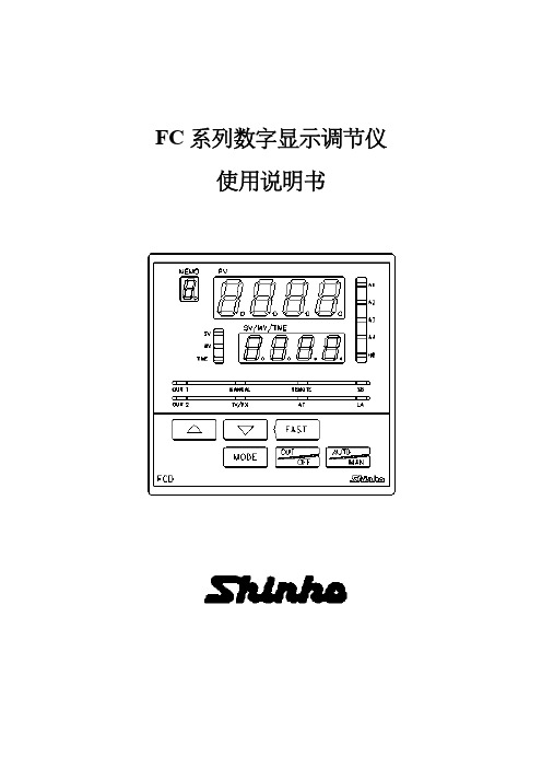
神港温控表JC使用说明书
FC系列中文操作说明(神港)
注意
• PID自整定(AT)的执行,请在试运行时实施。 • 为防止触电及发生调节仪故障,通电中请勿触及端子。 • 在实施端子锁紧或清洁作业时,必须在调节仪电源关闭的情况下执行。
通电期间作业,可能因触电而产生重大人身伤害。 • 在清洁时,请用柔软的干布。 • 应避免用硬物撞击和刮擦显示器。
1.2 模糊自整定 (1) 控制开始时,由以前的 PID 参数执行控制。 (2) 当控制结果因扰动或过程变化而异常时,仪表则监测此时的收敛状态,如有必要,自动调整 PID 参数。 (a)如收敛平滑且速度不慢,不改变 PID 值。 (b)如收敛速度太慢,仪表校正 PID 值使收敛变快。 (c)收敛过程中发现超调时,仪表自动调节 PID 值以避免发生超调。 (d)发生振荡时,调节仪检查波形和精细地自动调节 PID 值。 (3) 由内部开关设置,可使调节仪设定为带或不带模糊自行整定的 PID。
功能
1
控制方式
和
2
模糊自整定PID 控制 PID 控制 PD 控制 ON/OFF 控制
加热/冷却 3
加热(反作用)动作 冷却(正作用)动作
报警 1
无待机动作
待机
4
待机动作
报警 2
无待机动作
待机
5
待机动作
/
6
输入传感器
7*
K, J, R, B, N, PL- , Pt100, JPt100 S, E, T, C, 4 ~ 20mA, 0 ~ 20mA,
• 本调节仪使用说明书内所记载的注意及警告事项,请严格遵守。 如不遵守,可能导致重大伤害事故,请注意。
• 本说明书记载的内容可能会有变更。 • 本说明书尽可能予以周全叙述,如有不详或错误,敬请谅解,并予告知。 • 本调节仪计划安装在控制屏内,如果不是,请保证工作人员不能触摸到电源端子和高压部分。 • 不可将调节仪用于涉及人身安全的医学应用。 • 禁止任何未经授权的部分或全部复制本说明书。 • 本调节仪外壳是由阻燃树脂等做成的,请勿在易燃材料附近或易燃材料上安装本调节仪。
温控器说明书

温控器说明书尊敬的用户:感谢您选择使用我们的温控器产品。
为了确保您能正确并方便地使用该产品,我们特别为您撰写了以下说明书。
请在使用前仔细阅读本说明书,并按照操作指南正确操作。
一、产品概述我们的温控器是一款先进的智能控制设备,可实现对温度的精确控制和调节。
采用先进的技术,具备稳定可靠、操作简便的特点。
二、产品特性1. 温度调节范围广泛:本温控器支持调节范围为-10°C至80°C,满足不同环境下的温控需求。
2. 精确度高:采用高精度传感器,温度控制精度可达到±0.5°C,确保温度稳定性。
3. 显示直观:液晶显示屏可直观显示当前温度、设定温度以及相关操作信息。
4. 多种工作模式:支持手动模式和自动模式切换,可根据实际需求进行选择。
5. 时钟功能:具备定时启动和关闭功能,提供更加便利的使用体验。
6. 报警功能:当温度达到设定的上下限值时,温控器会发出警报提醒,确保温度安全。
三、安装步骤1. 请将温控器正确安装在所需控制的设备上,并确保电源连接正常。
2. 打开电源开关,温控器将自动进入工作状态。
3. 根据实际需求,设置温度范围、工作模式以及定时功能。
四、功能操作1. 温度调节:通过旋转控制按钮可以调节设定温度,逆时针旋转降低温度,顺时针旋转提高温度。
2. 工作模式切换:通过长按控制按钮,可实现手动模式和自动模式间的切换。
3. 定时功能设置:按下定时设置键,并依照提示进行相应设置,可以实现定时启动和关闭功能。
五、注意事项1. 请确保温控器的安装牢固,避免受到外力的振动或碰撞。
2. 请勿将温控器接触到水、油等液体,以免损坏设备。
3. 在进行温度调节时,请根据实际需求适度调整,避免过度升温或过度降温。
4. 请勿在高温或湿度较大的环境中使用温控器,以免影响性能和寿命。
5. 请勿随意拆卸温控器,否则会造成设备损坏或安全隐患。
六、故障排除1. 温控器无法启动:请检查电源是否接通,电源线是否连接正常。
JCRJCD-33A中文说明书

数字显示控制器JCR-33A,JCD-33A说明书为防止安装错误及防止事故发生,请将本说明书送至控制器使用者手中,谢谢!前言感谢使用本公司产品微电脑温度控制器[JCD-33A,或JCR-33A]本说明书是针对[JCD-33A,或JCR-33A]之设置方法,功能,操作方法等,予以说明,希望能详加阅读,充分理解后,使用本控制器。
为防止安装错误及防止事故发生,请将本说明书送至控制器使用者手中,谢谢!注意●本控制器应按说明书指定的规范使用。
若在规范外操作,将可能导致火灾或控制器故障,请注意。
●本控制器说明书内所记载的注意及警告事项,请严格遵守。
若未遵守其注意及警告事项,可能导致重大伤害事故,请注意。
●控制器需要定期维护。
●本说明书记载的内容,可能会有变更。
●本说明书尽可能予以周全叙述,如有不详或错误,尽请见谅,并予告知。
●为防止触电或出现故障,通电中请勿触及配线端子。
●如清洁本仪表,或锁紧端子时,请确认关闭控制器电源。
●本控制器如有污染,请用柔软干布擦拭干净。
不能使用香蕉水等浸渍类液体擦拭,因会导致本仪表变色及变形。
●显示器表面部分请勿以硬物刮敲。
●本控制器外壳使用耐燃性树脂制成,请勿将其安装在容易燃烧的物品附近,也不要在容易燃烧的物品上直接安装或与其接触。
●PID自整定(AT)请在试运行时执行。
目次1.型号1.1型号的说明1.2额定输入1.3型号铭牌的表示方法2各部位名称和功能3安装到控制屏3.1场地的选定3.2外形尺寸图3.3控制屏开孔图3.4CT(电流互感器)外形尺寸图3.5安装4.配线4.1端子配置图4.2配线例5.设定5.1设定流程图5.2主设定模式主设定1(SV1)主设定2(SV2)5.3基本参数设定模式自整定(AT)或自动复位(Auto Reset)设定OUT1比例带设定OUT2冷却侧比例带设定积分时间设定微分时间设定ARW设定OUT1比例周期设定OUT2冷却侧比例周期设定温度报警1(A1)设定温度报警2(A2)设定HB(加热器断线报警)设定LA(回路异常报警)时间设定LA(回路异常报警)动作幅度设定5.4辅助功能设定模式1设定值锁定选择(SV)主设定值上限设定(SV)主设定值下限设定传感器校正设定通信协议选择仪表编号设定通信速度选择奇偶校选择停止位选择5.5辅助功能设定模式2传感器选择刻度范围上限值设定刻度范围下限值设定小数点位置选择PV滤波时间常数设定(OUT1)输出上限设定(OUT1)输出下限设定(OUT1)输出ON/OFF动作间距设定(OUT2)冷却侧动作模式选择(OUT2)冷却侧输出上限设定(OUT2)冷却侧输出下限设定重叠区/死区设定(OUT2)冷却侧输出ON/OFF动作间距设定温度报警1(A1)动作方式选择温度报警2(A2)动作方式选择温度报警1(A1)常开/常闭选择温度报警2(A2)常开/常闭选择温度报警1(A1)动作间距设定温度报警2(A2)动作间距设定温度报警1(A1)动作延迟时间设定温度报警2(A2)动作延迟时间设定正/逆动作选择AT偏差设定SVTC偏置设定SV2显示选择输入异常时输出状态选择“OUT/OFF键”功能选择5.6控制输出“OFF”功能5.7自动/手动控制功能5.8输出操作量显示6.运行7.动作说明7.1 OUT1动作图7.2加热器断线报警动作图【特选功能:W】7.3 OUT1 ON/OFF动作图7.4 OUT2(加热/冷却控制)动作图【特选功能:D□】 7.5温度报警1,2(A1,A2)动作图7.6 SV1/SV2外部切换动作图8.控制动作说明8.1 PID说明8.2控制器的PID自整定8.3自动复位(余差校正)9.1标准规格9.2特选功能规格10.寻找和排除故障10.1显示部分10.2“键操作”部分 10.3控制输出部分11.显示符号一览表1.1型号的说明在下划线的上面,请依需求填入“型号”、“控制输出”、“输入”、“特选功能”等字符。
温控器说明书
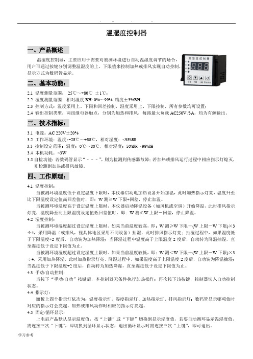
温湿度控制器一、产品概述温湿度控制器,主要应用于需要对被测环境进行自动温湿度调节的场合,用户可通过按键分别调整温湿度的上、下限值来控制加热或排风实现自动控制,显示方式为数码管显示。
二、基本功能:2.1 温度测量范围:-25℃~+80℃±1℃;2.2 湿度测量范围:相对湿度RH: 0%~99% 精度±3%RH;2.3 控制方式:温度采用上、下限和回差控制,湿度采用上、下限控制,所有参数均可设置;2.4 输出控制类型:两组继电器触点,分别为加热和排风,每路最大负载AC250V /3A,均为有源输出。
三、技术指标:3.1电源:AC 220V±20%3.2 工作环境:温度:-25℃~+55℃,相对湿度:<95%RH3.3控制设定范围:温度:0℃~80℃,相对湿度:50%RH~99%RH3.4 本机功耗:<3W3.5自检功能:若数码管显示“–––”,则为检测到传感器故障;若加热或排风运行过程中相应指示灯熄灭,则检测到加热或排风故障。
四、工作原理:4.1 温度控制:当被测环境温度低于设定温度下限时,本仪器启动电加热设备开始加温,此时加热指示灯亮,温度升至比下限温度设定值高回差值时,即:W测≥W下限+回差,停止加温。
当被测环境温度高于设定温度上限时,本仪器启动降温设备(如风机或空调)开始降温,此时排风指示灯亮,温度降至比上限温度设定值低回差值时,即:W测≤W上限-回差,停止降温。
4.2 湿度控制:当被测环境湿度超过设定湿度上限时。
如果当前温度较高,即:W测≥W下限+(W上限-W下限)×3÷4,采用降温(或排风,视具体地区采用不同设备)抽湿,此时排风指示灯亮;抽湿过程中,如果温度低于下限温度+2度后,自动转为加热降湿;当降湿过程中温度高于上限温度-2度后,自动转为降温抽湿,直至湿度低于设定下限值为止。
当被测环境湿度超过设定湿度上限时。
如果当前温度较低,即:W测<W下限+(W上限-W下限)×3÷4,采用加热降湿,此时加热指示灯亮,降湿过程中,如果温度高于上限温度-2度后,自动转为降温抽湿;当温度低于下限温度+2度后,自动转为加热降湿,直至湿度低于设定下限值为止。
日本SHINKO神港温控器JC系列 中文选型说明书
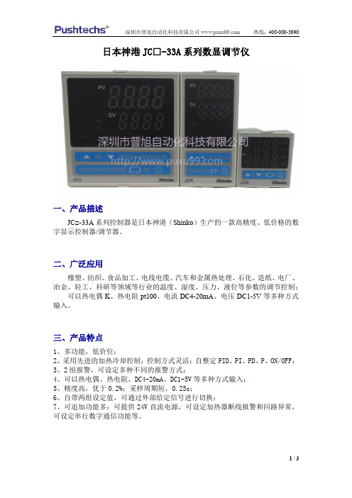
日本神港JC□-33A系列数显调节仪
一、产品描述
JC□-33A系列控制器是日本神港(Shinko)生产的一款高精度、低价格的数字显示控制器/调节器。
二、广泛应用
橡塑、纺织、食品加工、电线电缆、汽车和金属热处理、石化、造纸、电厂、冶金、轻工、科研等领域等行业的温度、湿度、压力、液位等参数的调节控制;
可以热电偶K、热电阻pt100、电流DC4-20mA、电压DC1-5V等多种方式输入。
三、产品特点
1、多功能,低价位;
2、采用先进的加热冷却控制;控制方式灵活;自整定PID、PI、PD、P、ON/OFF;
3、2组报警,可设定多种不同的报警方式;
4、可以热电偶、热电阻、DC4-20mA、DC1-5V等多种方式输入;
5、精度高,优于0.2%;采样周期短,0.25s;
6、自带两组设定值,可通过外部给定信号进行切换;
7、可追加功能多:可提供24V直流电源,可设定加热器断线报警和回路异常,可设定串行数字通信功能等。
四、日本shinko神港温控器JC系列简易选型表
注:更多相关产品、各行业温度控制系统解决方案详情、资料下载>>>>>>>>请进入普旭官网:
>>>>>>>>咨询热线:400-000-3990。
日本神港 JC-33A 系列通用控制器操作说明书

日本神港JC-33A系列通用控制器操作说明书日本神港(SHINKO)株式会社拥有五十余年温度控制的丰富经验,在工业控制仪表领域以其独特的科研与开发为先导,推出了JC-33A系列通用型通用控制仪表,它采用了最先进的加热冷却双PID算法,无超调,无欠调,输入用户自由组态,双设定值,手自动功能,通讯功能,回路断线报警,JC系列仪表已通过ISO9001质量认证,广泛应用于橡胶,实验仪器,空调,纺织,汽车,食品,电缆电线等工业的温度,湿度,压力,液位元等控制。
(1)PV测量值显示 (9)TX/RX通讯指示红色LED显示实际测量值 当处于通讯状态时,黄色LED亮(2)SV设定值显示 (10)A1报警1指示 绿色LED显示实际设定值或手动输出值 当报警1动作时,红色LED亮(3)设定值1指示 (11)A2/L2报警指示当使用设定值1时,绿色LED亮 当报警2动作或回路断线时,(4)设定值2显示 红色LED亮当使用设定值2时,黄色LED亮 (12)增加键(5)输出1指示 按此键增加数值当输出1工作时,绿色LED亮 (13)减少键(6)输出2指示 按此键减少数值当输出2工作时,黄色LED亮 (14)方式键(7)HB加热器断线报警 按此键并配合其它键使用可进入各级菜单当发生加热器断线或传感器断线时, (15)OUT/OFF键红色LED亮 按此键一秒钟可关闭仪表输出 ;(8)AT自整定指示 按三秒钟可输出百分比当处于自整定状态时,黄色LED亮(1) 仪表选型JC □- □ 3 A- □/ M, □JC SERIES D JCD (W96×H96×D100mm ) R JCR (W48×H96×D100mm ) 尺寸 SJCS (W48×H48×D100mm ) 1适用于JCD ,JCR 机种 序 号 2仅适用于JCS-23-A □/□机种 控制动作 3PID 控制(控制方式可以选择) 警报1(A1) A多种动作系统(动作方式可选择) RRelay 继电器接点,1a 1b (JCS:1a) SDC 电压输出(驱动SSR 用):12+20V 控制输出(O U T ) ADC 电流输出:4~20mA M多种范围输入系统(输入种类热电偶、电阻体可选择) ADC 电流输入:0~20mA ,4~20mA (JCS 可于M 入力中选择此入力) 入 力 V DC 电压输入:0~1V ,0~10V ,1~5V(JCS 可于M 入力中选择0~1V )A2 警报2(A2)(动作方式可选择) W(5A)等级:5A W(10A)等级:10AW(20A)等级:20AW(50A)加热器 断线警报 等级:50A DR Relay 继电器接点:1aDS DC 电压输出(驱动SSR 用): 12+20V 最大40mA DA 控制输出 加热、 冷却控制 (JCS 无)DC 电流输出:4~20mA 负荷电阻:最大550ΩC5 串行通信 RS-485LA 回路断线警报SM 设定值记忆外部切换功能(仅JCS 为附加特殊功能)BK 黑色IP 防尘·防滴(IP54)特殊功能(需指定) TC 外壳接线端子防护<注>:特殊功能并非每一机种均可指定采用,请参照各别机种详细目录。
DCL说明书

(7) 窗口 说 明
窗口编号 内容 设 定值1(SV1)
1-1
说明
*此窗 口设 置第 一个 设定值 *设 置 范围 :传 感器 下限~传 感器 上限 *出厂 值为0
AT自整 定 2-1
*此 窗口设 置仪 表自 整定 功能 *当 处 于自 整定 期间,仪 表AT指示 灯闪 亮
*自 整 定结 束后,P,I, D,A RW参 数自 动 存 储
附: 在 高 低 温 控 制中,左边的DCL测试高 温区温度,右边的DCL测试低温区温度 再 温 湿 度 控 制 中,左边的DCL测试温度,右边的DCL 测试湿度
DCL: 左边
右边
通 信 协 议 :Modbus RTU协议 通信地址: 1
通 信 速 率 :9600bps 校验 选 择:Modbus RTU方式 停止位: 1
(5)D C L - 3 3 A操 作 流程图
按键
P V/ SV显 示
控制输出关闭功能 按 键1秒钟
输出 手动 操作 按 键3秒 钟
+
[主 设置 方式] 2-1[子设置 方式]
设 定 值1(SV1) AT自 整 定
+ 3秒
+隐藏 键 3秒
3
-1[辅助 设置方 式1]
设定之锁定功能
[辅传助感设器置选方择 式2 ]4
W(50A) C5
互 感 器 电 流 :50 A RS -485通 讯
(2) 输 入范 围(用 户在仪表 内自由选择)
输入类型
输入范围
K
- 2 0 0 ~ 1 3 7 0摄 氏 度
- 1 9 9 . 9~ 4 0 0. 0摄 氏 度
J
- 2 0 0 ~ 10 0 0摄 氏 度
Extech TM100数字J K类温度计说明书
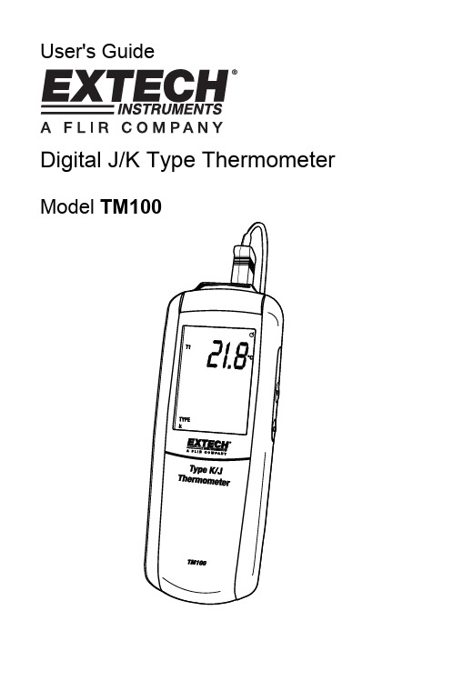
User's GuideDigital J/K Type Thermometer Model TM100IntroductionCongratulations on your purchase of the Extech TM100 Digital Thermometer with K/J single-type input. This meter is shipped fully tested and calibrated and, with proper use, will provide years of reliable service.SafetyTo prevent personal injury or meter damage, use the meter only as specified in this guideMeter DescriptionMeter1. Thermocouple input connector2. Function buttons (Power, Enter, C-F-K)3. Function buttons (Hold, MAX/MIN, Set)4. LCD display5. Battery compartmentDisplay1. Setup2. Offset option3. Hold mode4. Auto power off5. Upper display T1 reading6. Temperature units7. Lower display (max, min,avg, offset value of T1)8. Max, Min and Average9. Time display10. K/J type thermocouple11. Low BatteryOperationConnecting thermocouples1. This meter accepts any K/J-type thermocouple with spade lugs (sub-miniature typewith one spade wider than the other).2. Plug the thermocouple into the meter's thermocouple input jack.Measuring1.thermometer will display the first temperature reading (upper display).C-F-K button to select the desired temperature unit of measure. Athe2. Pressdisplay icon will reflect the selection.3. Contact the object to be measured with the probe. Read the measured temperaturein the display.Note: If the display indicates “OL” the temperature is outside the measurementrange. The display shows "- - - -" when a thermocouple is not connected.MAX/MIN/AVG modePress MAX/MIN to capture and step through the maximum (MAX), minimum (MIN) and average (AVG) temperature values. These values will be shown in the lower display with an elapsed time reference below (hrs:mins , mins:sec).1. Press MAX/MIN to enter this mode.2. Press MAX/MIN to step through maximum, minimum and average readings.3. Press MAX/MIN for 3 seconds to return to normal mode.Data HoldPress the HOLD button to freeze the reading in the display. HOLD will appear at the top right of the display. Press the HOLD button again to return to normal operation mode. BacklightPress SETUP button to turn backlight off/on.Setup optionThe setup option is used to change the thermocouple type, to turn the sleep mode off/on and to adjust the thermocouple offset.Note: In the setup mode, the upper display shows menu items and lower display shows settings.SET button for 3 seconds to enter or exit setup. When the thermometer1. Presstheis in Setup mode, the display shows SETUP.Set Type J or K thermocouple1. Press ▲ or ▼to scroll to the “TYPE” setting (shown bottom left).2. Press ENTER to choose the option.3. Press ▼ to toggle between J and K.4. Press the SET button for 3 seconds to save the setting and return to normal mode.Set Sleep/Non-sleep modeThe thermometer enters sleep mode by default. The meter will automatically shut off after 20 minutes if no button press occurs for 20 minutes. When the thermometer is in Setup mode, the display shows SETUP.1. Press▲ or ▼to scroll to the “SLP” setting.ENTER to chose the option “On” or “OFF” will appear in the display.2. Press▼ to select on or off..3. Press4. PressENTER to store the new setting in memory.SET button for 3 seconds to return to normal mode.5. PressSet OffsetUse the offset option in Setup (T1menu item) to adjust the thermometer’s readings to compensate for known temperature offset at a specific temperature. The allowableadjustment range is ± 5.0°C or ± 9.0 °F.1. Plug the thermocouple into the input connector.2. Place the thermocouple into the known, stable temperature environment (such as aice bath or dry well calibrator). Allow the reading to stabilize.3. Press▲ or ▼to scroll to the “T1” option and press ENTER.4. Change the offset temperature reading (upper display) by pressing ▼until itreaches the desired temperature.SET button for 3 seconds to return to normal mode.5. PressReplacing the Batteries1. Turn off the thermometer.2. Loosen the screw and remove the battery door.3. Replace the AAA batteries.4. Replace the battery door and tighten the screw.Support line (781) 890-7440 TechnicalSupport:Extension200;E-mail:******************Repair&Returns:Extension210;E-mail:*****************Product specifications subject to change without notice For the latest version of this User Guide, Software updates, and other up-to-the-minute product information, visit our website: Extech Instruments Corporation, 285 Bear Hill Road, Waltham, MA 02451 SpecificationsTemperature Range:K type thermocouples-200°C to 1372°C (-328°F to 2501°F) J type thermocouples-210°C to 1100°C (-346°F to 2012°F) Temperature accuracy:T1 Above –100 0C (-148 0F)± [0.15%rgd+1°C (1.8°F)] T1 Below –100 0C (-148 0F)± [0.5%rgd+2°C (3.6°F)] Display Resolution:0.1°C /°F /°K <1000, 1°C /°F /°K >1000 Battery: “AAA “1.5V×3Operating Temperature:0°C to +50°C (40°F to +122°F) Storage Temperature:−10°C to +50°C (14°F to +122°F) Dimensions:8.7 x 2.5 x 1.1” (220 x 63 x 28mm) Weight:7oz (200g) WarrantyEXTECH INSTRUMENTS CORPORATION (A FLIR COMPANY) warrants this instrument to be free of defects in parts and workmanship for one year from date of shipment (a six month limited warranty applies to sensors and cables). If it should become necessary to return the instrument for service during or beyond the warranty period, contact the Customer Service Department at (781) 890-7440 ext. 210 for authorization or visit our website for contact information. A Return Authorization (RA) number must be issued before any product is returned to Extech. The sender is responsible for shipping charges, freight, insurance and proper packaging to prevent damage in transit. This warranty does not apply to defects resulting from action of the user such as misuse, improper wiring, operation outside of specification, improper maintenance or repair, or unauthorized modification. Extech specifically disclaims any implied warranties or merchantability or fitness for a specific purpose and will not be liable for any direct, indirect, incidental or consequential damages. Extech's total liability is limited to repair or replacement of the product. The warranty set forth above is inclusive and no other warranty, whether written or oral, is expressed or implied.Calibration and Repair ServicesExtech offers repair and calibration services for the products we sell. Extech also provides NIST certification for most products. Call the Customer Care Department for information on calibration services available for this product. Extech recommends that annual calibrations be performed to verify meter performance and accuracy.Copyright © 2009 Extech Instruments Corporation (a FLIR company)All rights reserved including the right of reproduction in whole or in part in any form.。
温度控制器说明书

温度控制器说明书温度控制器说明书1. 简介温度控制器(Temperature Controller)是一种用于测量和控制温度的设备。
它广泛应用于工业、科研、农业等领域,用于保持恒定的温度环境以满足特定的需求。
本说明书将介绍温度控制器的基本使用方法和注意事项。
2. 功能特点- 温度测量:温度控制器可以精确测量环境或物体的温度,并实时显示在屏幕上。
- 温度设定:用户可以通过温度控制器设置所需的温度值。
- 温度控制:温度控制器可以根据用户设定的温度值自动控制加热或制冷设备,以保持温度稳定。
- 报警功能:当温度超过或低于设定的阈值时,温度控制器会发出警报以提醒用户。
- 数据记录:温度控制器可以记录温度数据,并提供导出或打印功能。
3. 使用方法3.1 连接将温度探头插入温度控制器的探头接口,并确保连接牢固。
3.2 开机按下温度控制器的电源按钮,待显示屏上出现启动画面后,即表示温度控制器已成功开机。
3.3 设定温度使用温度控制器上的设定按钮或旋钮,调整显示屏上的温度数值,以设定所需的目标温度。
3.4 启动控制在设定好目标温度后,按下温度控制器上的启动按钮,控制器将开始控制加热或制冷设备以维持目标温度。
3.5 报警功能如果温度超过或低于设定的阈值,温度控制器将发出警报声。
在警报触发时,及时采取相应措施以避免温度波动过大。
4. 注意事项- 请勿在温度控制器受潮或温度较高的环境中使用,以免损坏设备。
- 在使用过程中请注意安全,避免触摸温度探头以免烫伤。
- 调节温度时,请逐步调整,避免温度波动过大。
- 定期校准温度控制器以确保测量的准确性和稳定性。
- 在长时间不使用温度控制器时,请断开电源并存放在干燥通风的地方。
5. 维护和保养- 温度探头需要定期清洁和校准,以保证测量的准确性。
- 定期检查温度控制器的电源线和连接线是否损坏。
- 如有任何故障或异常情况,请及时联系售后服务。
6. 常见问题解答问:温度控制器无法开机怎么办?答:请检查电源线是否连接正常,并确保电源插座有电。
温度开关和温度限制器说明书

J Household appliances J Electronics J Fan heatersJ Automotive industry ApplicationsJ More safety by self hold types J Various housings J Manual resetJ Customized ratingsBenefitsSeries D switches are based on a complex system consisting of a contact spring unit and a thermo-bimetal snap-disc . When heating up to the fixed switching point, the contact opens and thus interrupts the power circuit.They are very flexible to use: Due to the different types of reset and the adjustable current sensitivity for quick shutdowns, the D switches offer high quality solutions , especially in very specific safety concepts.Temperature switch with an automatic reset D10: After a certain cooling phase (temp. hysteresis) the contact switches back automatically.Temperature limiter with manual reset D20: After opening the contacts and the subsequent cooling the contacts remain open until a manual reset is performed on the reset pin.Temperature switch with electr. self-hold D30 (230V) / D40 (120V): After opening the contacts the switch is heated by a parallel connected resistor and thus kept open. The automatic reset is only performed through a mains disconnection, or off-switching of the device in which the temperature switch is installed.For special applications version P is available with a very low self heating rate.Manual reset: The maximum operating force must not exceed 6 N. The control should not be reset before the starting conditionsare reached, meaning there should be a satisfactory cooling down time! Technical data on request.with housingFor current-time based types (execution D, J, K, L, M, P, R, V) the following information must be provided:in Amps at which the switch must not respond.in Amps at which the switch must respond and the response time tAmbient temperatures which could be experienced both in normal operation and in switching conditions.P types have terminals of CuFe2P materialD series switches are also available with lead wires in combination withinsulating shrink sleeves.Technical data on request.Current vs. response timeTest conditions:Measurement in air flow and lead wires of 1.5 mm 2.TCO variations for current-time based applications.Ordering exampleMarkingcurrent I 0 [A]r e s p o n s e t i m e t 0 [S ]D 10Vcurrent I 0 [A]D10V type and execution E country (D=Germany)12005response temperature (120°C), tolerance (± 5°C)047date of manufacture (May 2017)D12D type and execution H country (H=China)--123customized type with drawing number 047customized type with drawing number10/2021-Technical subject to change without noticeT äschenwaldstraße 3 75181 Pforzheim DeutschlandTel.: +49 7231 787-0 Fax: +49 7231 787-155******************www.microtherm.deMicrotherm GmbHD, J, K, L M, P , R, V51015051015202530。
温控器说明书
用户订货时需按本说明书的功能分类,注明所需仪表的型号。用户对仪表的传感器规格或其他方面有特殊要求的,订货前请说明。
性能指标
工作温度:-10℃~+55℃
安全指导
在安装、操作和运行本温控器前,请仔细阅读本说明书,并妥善保管。
本温控器有危险电压,并监控电力变压器,如果不按照本说明书的规定操作可能会导致财产损失或人员严重受伤甚至死亡。
只有合格的技术人员才允许操作本温控器,在进行操作之前,要熟悉说明书中所有安全说明、安装、操作和维护规程。本温控器的正常运行取决于正确的运输、安装、操作和维护。
7、手动启停风机功能:
按“手动”键,风机启动,再按“手动”键,风机关闭;若仅按一次“手动”键,风机启动10分钟后自动关闭。
本功能也可以作为测试风机功能用。
8、风机定时启停功能:
温控器提供定时启动风机的功能,用于防止风机长时间不运行而发生故障。用户可在面板上进行0~200个小时任意设置(当设置为0时,表示取消此项功能),定时时间到达后,风机自动运行2分钟后停止。出厂时设置为24小时。风机每次定时启动运行时间为2分钟,用户无法自行修改。
3、风机启停功能:
当三相绕组中任意一相绕组温度达到设定的风机启动温度时,风机自动启动,风机指示
灯亮。当三相绕组温度全部下降到设定的风机停止温度时,风机自动关闭,风机指示灯熄灭。风机继电器触点容量为AC220V/7A。风机如需保护,请外接保护装置。
4、超温报警功能:
当三相绕组中任意一相绕组温度达到设定的超温报警温度时,温控器发出声光报警,并接通报警输出端子,向远方的控制柜送出一开关信号,供控制柜启动声光报警系统。继电器触点容量为:AC220V/3A或DC28V/3A。
温控面板使用方法

一、各功能键说明:: 开/关: 主功能键: 次功能键: 显示加热版温度二、萤幕符号说明: 闪烁时,表示加热开关开启: 表示加热开关关闭,只显示温度(不耗电): 表示按照设定程式阶段性加热建议: 在北京使用,不要出现三、简易操作步骤:.在关机状态(萤幕不显示),轻按 (0.1秒),用↑↓调整萤幕上的温度数示至(35-40实木地板,或复合实木地板)或(40-45复合地板,非实木复合地板)或(40-50石材),调整后5秒钟,温控器自动呈现开机状态,萤幕上之数字转为实际温度。
.按↑↓设定希望达到之室内温度(建议20至25),5秒钟后,温控器数字转为实际室温。
.(实际室温高于设定温度时,不加热).十分钟之后,可随时按,可短暂显示加热板温度。
.按三秒钟以上,即刻关闭加热板与温控器。
注意:操作过程中,若萤幕出现或,可轻按一至二次使其消失。
温控器自动控温设定自动控温设定前言:1.周一至周五(Mon,Tue,Wed,Thur,Fri)为同一组温控程式.2.假日,周六至周日(Sat, Sun)为同一组温控程式.3.每一组温控程式,必须设定五个时段的不同温度.4.自动控温设定时或运作时,按' M'键至显示' '及' '5.自动控温各时段的时间或温度,都是按' '.内建出厂原始设定程式如下表:设定操作步骤:1.确定温控器在开机状态,按'M'至萤幕同时显示' '及' '.2.以后,祗须按' ',被调整的部位会闪烁,按上下来调整时段及温度。
(1)按第一次' ',萤幕显示(Mon, Tue, Wed, Thu, Fri)及时间处的06在闪烁,按上下改变'时' ;如果不按上下而再按' ',则06固定而开始闪烁00;如果按至07后再按' ',则07固定而开始闪烁00。
神港温控表JC使用说明书
当控制输出功能停止时,PV 显示[OFF]。要打开控制输出功能,按开/关键 1 秒以上。
表 3.2-1 输入类型
℃
PV 显示
SV 显示
℉
PV 显示
SV 显示
K
K000
JF
1800
E Pt100
EC PT .C PT C
800 850.0 850
EF PT .F PT F
A
直流电流输入 DC 4~20 mA、0~20 mA
V
直流电压输入 DC 0~1 V、0~10 V
A2
报警输出 2
LA
回路异常报警
DR DS DA
控制输出(OUT2) 加热冷却控制
继电器触点 无触点电压 SSR 电流 DC 4~20 mA
特选功能
W(20) W(50)
加热断线报警
5A,10A,20 A 50 A
*2
绝对值下限报警
输入量程最小值~输入量程最大值℃(℉)
*2
上限报警加待机
-输入量程~输入量程℃(℉)
*1
下限报警加待机
-输入量程~输入量程℃(℉)
*1
上/下限报警加待机
-输入量程~输入量程℃(℉)
*1
·当输入有小数点时,最小值为-199.9,最大值为 999.9。
*1:对直流输入,输入量程为输入范围标定值。
量程 0~1370℃ 0~1000℃
0~800℃ -200~850℃ -199.9~850.0℃ -200~500℃ -199.9~500.0℃
0~2500℉ 0~1800℉ 0~1500℉ -300~1500℉ -199.9~999.9℉ -300~900℉ -199.9~900.0℉
温控仪使用说明范文
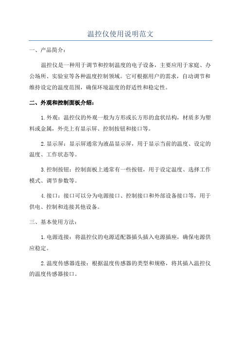
温控仪使用说明范文一、产品简介:温控仪是一种用于调节和控制温度的电子设备,主要应用于家庭、办公场所、实验室等各种温度控制领域。
它可根据用户的需求,自动调节和维持设定的温度范围,确保环境温度的舒适性和稳定性。
二、外观和控制面板介绍:1.外观:温控仪的外观一般为方形或长方形的盒状结构,材质多为塑料或金属,外壳上有显示屏、控制按钮和接口等。
2.显示屏:显示屏通常为液晶显示屏,用于显示当前的温度、设定的温度、工作状态等。
3.控制按钮:控制面板上通常有一些按钮,用于设定温度、选择工作模式、调节参数等。
4.接口:接口可以分为电源接口、控制接口和外部设备接口等,用于供电、控制和连接其他设备。
三、基本使用方法:1.电源连接:将温控仪的电源适配器插头插入电源插座,确保电源供应稳定。
2.温度传感器连接:根据温度传感器的类型和规格,将其插入温控仪的温度传感器接口。
3.设定温度:通过控制按钮,在显示屏上设定所需的温度范围。
根据不同的温控仪型号,设定方法可能略有差异,但通常需要按下设定按钮,然后使用加减按钮来调节目标温度,并保存设定值。
4.选择工作模式:温控仪通常提供多种工作模式,如制冷模式、加热模式、自动模式等。
根据需要,选择相应的工作模式,并进行设定。
5.调节参数:一些温控仪还提供一些可调节的参数,如温度回差、控温精度等。
根据需要,进行相应的参数调节。
6.启动和关闭:根据所设定的温度和工作模式,按下启动按钮使温控仪开始工作。
需要关闭时,按下关闭按钮将其停止工作。
四、注意事项:1.请阅读说明书:在使用温控仪前,请仔细阅读产品的说明书,了解其功能和使用方法。
2.正确安装传感器:温度传感器是温控仪的重要组成部分,需正确安装在需要测量温度的地方,避免误差。
3.避免灰尘和水汽:避免温控仪长时间处于灰尘多、湿度高的环境中,以免影响其正常工作。
4.保持通风:温控仪应放置在通风良好的位置,避免阳光直射和高温环境,以保证其散热效果和寿命。
PC-935日本神港温控表操作指导书
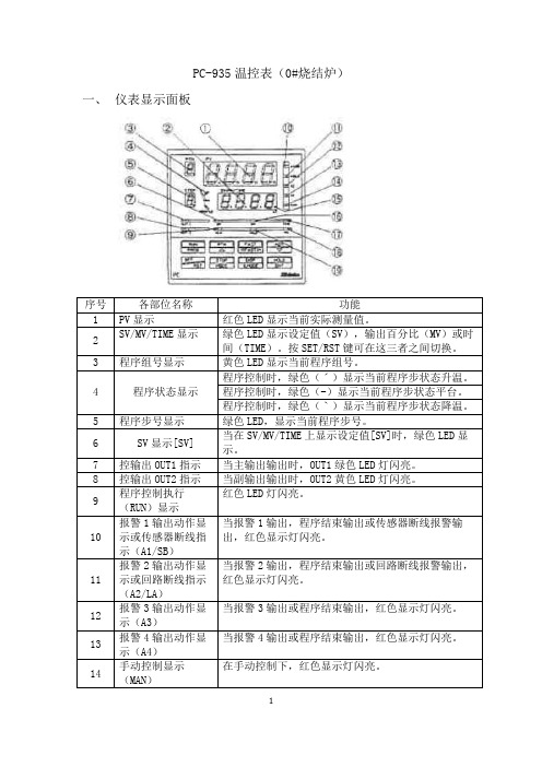
PC-935温控表(0#烧结炉)一、仪表显示面板键二、程序跳步由程序控制方式运行时,按键或“跳步”按钮,可跳到下一步程序。
三、自动/手动功能设置按,再按几次直到出现,再按键进入自动/手动输出方式选择:可选择输出由仪表控制(自动)还是手动方式。
四、程序控制方式1、程序设置1.1接通温度调节器电源,按进入设置模式,显示模式设置方式。
1.2按进入模式号设置方式,按△或▽键选择将要编程的程序组(组号在PTN框显示)。
1.3按进入步SV(设定)值,再按几次可分别设定各步的SV值(步号显示在STEP窗口,0-9共10步),按△或▽键设置具体参数。
1.4按进入步时间,再按几次可分别设定各步的时间值(步号显示在STEP窗口0-9共10步),按△或▽键设置具体参数。
1.5按进入PID模块号,TS1-TS8时标模块号,,等待模块号,默认值为0,可不修改。
1.6按返回显示画面。
2、设置各模块参数值(仅作了解)按,再按进入模块设置方式,可设置PID模块,时标模块,等待模块,报警模块,输出模块的参数。
2.1按进入PID模块:按依次可设置0-9号共10个PID模块的主比例带,积分时间,微分时间,抗积分饱和,副比例带(有副输出时有效)2.2 再按进入时标功能:按依次可设置提供在程序步控制期间,8个时间信号的输出。
共有8组(开/关为一组)模块数据可设置。
2.3再按进入等待模块数据的设定:按,在此设置0-9共10个等待值,在程序控制期间,当步程序结束时,测量值仍未达到【设定值-等待值】或【设定值+等待值】,那么将不进入下一步程序,而进入等待状态STEP窗口闪烁,直到按进入下一步程序,或按键停止程序。
2.4 再按进入报警模块设置:按,设置A1-A4报警点各步的报警数值,按△或▽键设置具体参数。
2.4 再按进入输出功能模块设置:按,在此可设置10个数据模块中的参数(主输出上/下限,副输出上/下限,主输出的改变速率)。
温度控制器使用说明书
温度控制器使用说明书一、产品概述温度控制器是一种用于控制和调节温度的设备。
它可以实时监测环境温度,并按照预设的温度范围进行自动控制,以确保温度保持在设定值内。
二、产品组成1.主机:包含显示屏、按键和控制电路等组件,用于设置和监控温度控制器的工作状态。
2.传感器:用于感知环境温度的变化,并将其转化为电信号,传输给主机进行处理。
3.输出端口:用于连接外部设备,如加热器、冷却器等,以实现温度调节。
三、使用步骤1.连接电源:将温度控制器插入电源插座,并确保电源稳定。
2.连接传感器:将传感器插入温度控制器的传感器接口中,并确保连接牢固。
3.设置温度范围:按照产品说明书中的指引,通过按键设置所需的温度范围。
4.连接外部设备:根据需要,使用合适的电缆将外部设备连接至温度控制器的输出端口上。
5.开机:按下电源按钮,温度控制器将开始运行,并在显示屏上显示当前温度及工作状态。
6.调试和调节:根据实际需要,适时调整温度控制器的参数,以达到预期的温度控制效果。
四、注意事项1.请确保温度控制器在通风良好的环境中工作,避免遮挡或靠近高温的物体。
2.避免温度控制器长时间暴露在潮湿、尘土等有害环境中,以免影响正常使用寿命。
3.使用前请认真阅读产品说明书,并按照要求正确操作,以免因误操作导致设备损坏或操作失误。
4.在设置温度范围时,请合理选择上下限,避免因温度波动过大造成设备故障或无法达到所需温度。
5.如遇到温度控制器异常工作或其他问题,请及时联系售后服务中心进行咨询或维修。
五、常见问题解答1.温度控制器显示屏无法正常工作怎么办?答:请检查电源接口是否接触良好,确认电源供电充足,并检查是否有异常开关或损坏的部件。
2.温度控制器无法控制温度在设定范围内怎么办?答:请确认传感器连接是否正确,温度控制器和外部设备的连接是否稳固,并适时调整温度范围和控制参数。
3.温度控制器显示温度与实际温度不一致怎么办?答:请检查传感器的位置是否合理,避免受到外部干扰,如阳光直射或其他热源等。
温控器使用说明范文
温控器使用说明范文第一部分:温控器概述温控器是一种设备,用于控制室内温度,并保持室内温度在设定的范围内。
温控器通常由温度传感器、控制器和执行器组成,可以自动地调控供暖、通风或冷却系统来实现室内温度的控制和维持。
温控器用途广泛,可以应用于家庭、办公室、商业建筑等各种场所。
使用温控器可以提高室内舒适度,节省能源,并保护环境。
本文将详细介绍温控器的使用方法和常见问题解答。
第二部分:温控器使用方法1.开机和关闭在使用温控器之前,请确保电源已连接,然后按下电源按钮,等待温控器启动。
在关闭温控器时,按下电源按钮并保持按住,直到屏幕上的指示灯熄灭即可。
2.温度设定温控器通常具有温度设定功能。
通过设定期望的室内温度,温控器将自动调节供暖或冷却系统的工作,以达到所需的温度。
根据温控器型号的不同,设定温度的方法可能会有所不同,一般可通过旋钮、按钮或触摸屏来进行设定。
具体的操作方法请参考温控器的用户手册。
3.模式选择温控器通常具有多种工作模式,并可以根据需要选择不同的模式。
常见的模式包括供暖模式、冷却模式、通风模式和自动模式。
通过切换不同的模式,温控器将根据设定的温度自动调节相应的设备工作状态。
具体的操作方法请参考温控器的用户手册。
4.定时功能温控器通常具有定时功能,可以预先设置温度调节的时间。
通过设定开机和关闭的时间,温控器可以在指定的时间自动启动或关闭,并进行相应的温度控制。
使用定时功能可以节省能源,并提高使用的便利性。
具体的操作方法请参考温控器的用户手册。
5.节能提示温控器通常具有节能提示功能,会根据当前的室内温度和设定温度给出相应的建议。
当温度过高或过低时,温控器会发出声音或显示警报,提示用户调整设定温度或检查相关设备。
请注意,节能提示仅为建议,并非强制执行,用户可以根据自己的需求进行选择。
第三部分:常见问题解答1.温控器显示错误代码怎么办?2.温控器无法调节温度怎么办?3.温控器无法启动怎么办?总结:。
神港JC系列通讯说明书
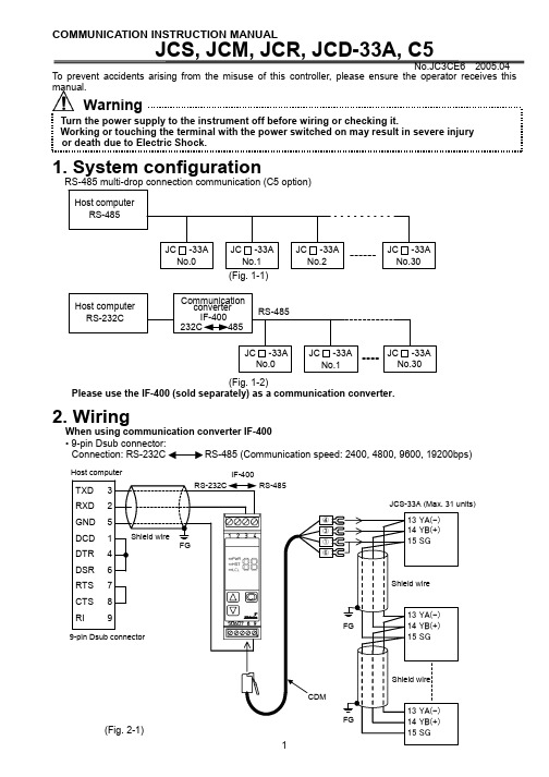
COMMUNICATION INSTRUCTION MANUALJCS, JCM, JCR, JCD-33A, C5No.JC3CE6 2005.04 To prevent accidents arising from the misuse of this controller, please ensure the operator receives this manual.WarningTurn the power supply to the instrument off before wiring or checking it.Working or touching the terminal with the power switched on may result in severe injury or death due to Electric Shock.1. System configurationRS-485 multi-drop connection communication (C5 option)(Fig. 1-1)(Fig. 1-2)Please use the IF-400 (sold separately) as a communication converter. 2. WiringWhen using communication converter IF-400 • 9-pin Dsub connector: Connection: (Communication speed: 2400, 4800, 9600, 19200bps)Host computerConnection: (Communication speed: 2400, 4800, 9600, 19200bps)Shield wireConnect only one side of the shield wire to the FG terminal so that current cannot flow to the shield wire.(If both sides of the shield wire are connected to the FG terminal, the circuit will be closed between the shield wire and the ground. As a result, current will run through the shield wire and this may cause noise.)Be sure to ground the FG terminal. Terminator (Terminal resistor)Do not connect terminator with the communication line because each JC -33A has built-in pull-up and pull-down resistors instead of a terminator.-33A• It is necessary to set the instrument number individually to the JC -33A when communicating byconnecting plural units in serial communication (C5 option).Select a communication speed of the JC -33A in accordance with that of the host computer. • For the instrument number setting and communication speed, refer to the instruction manual for JC -33A.4. Communication procedureCommunication starts with command transmission from the host computer (hereafter Master) and ends with the response of the JC -33A (hereafter Slave).• Response with datathe master sends the reading command, the slaveresponds with the corresponding set value or current • Acknowledgementthe master sends the setting command, the slaveresponds by sending the acknowledgement after theprocessing is terminated. • Negative acknowledgement the master sends non-existent command or value out of the setting range, the slave returns the negative • No responseaddress is set, or when there is a communication error(framing error or checksum error), or when LRC or CRCdiscrepancy is detected.Host computerCommunication timing of the RS-485 (C5 option)Slave sideWhen the slave starts transmission through RS-485 communication line, the slave is arranged so as to provide an idle status (mark status) transmission period of 1 or more characters before sending the response to ensure the synchronization on the receiving side.The slave is arranged so as to disconnect the transmitter from the communication line within a1 character transmission period after sending the response.Master side (Notice on programming)Set the program so that the master can disconnect the transmitter from the communication line withina 1 character transmission period after sending the command in preparation for reception of theresponse from the slave.To avoid the collision of transmissions between the master and the slave, send the next command after carefully checking that the master received the response.5. Shinko protocol5.1 Transmission modeShinko protocol is composed of ASCII codes.Hexadecimal (0 to 9, A to F), which is divided into high order (4-bit) and low order (4-bit) out of 8-bit binary data in command is transmitted as ASCII characters.Data format Start bit : 1 bitData bit : 7 bitsP arity : EvenS top bit : 1 bitError detection: Checksum5.2 Command configurationAll commands are composed of ASCII. The data (set value, decimal number) is represented withhexadecimal number, and ASCII code is used.The negative numbers are represented with 2's complement.(1) Setting command(2) Reading command(3) Response with data(5) Negative acknowledgementHeader: Control code to represent the beginning of the command or the response.ASCII codes are used.Setting command, Reading command : 02H fixedResponse with data, Acknowledgement : 06H fixedNegative acknowledgement : 15H fixed Number of charactersNumber ofcharactersNumber ofcharacters Number ofcharactersNumber ofcharactersAddress (Instrument number): Numbers by which the master discerns each slave. Instrument number 0 to 94 (00H to 5EH) and Global address 95 (7FH) The numbers (20H to 7EH) are used by giving 20H of bias, because 00H to 1FH are used for control code. 95 (7FH) is called Global address , which is used when the same command is sent to all the slaves connected. However, the response is not returned.Sub address : 20H fixedCommand type : Code to discern Setting command (50H) and Reading command (20H) Data item : Data classification of the command object Composed of hexadecimal 4 digits (Refer to the Communication command table) Data : The contents of data (set value) depend on the setting command Composed of hexadecimal 4 digits (Refer to the Communication command table) Checksum : 2-character data to detect communication errors Delimiter : Control code to represent the end of command 03H fixed Error code : Represents an error type. Composed of hexadecimal 1 digit. 1 (31H)-----Non-existent command 2 (32H)-----Not used 3 (33H)-----Setting outside the setting range 4 (34H)-----Status unable to set (e.g. AT is performing) 5 (35H)-----During setting mode by keypad operation5.3 Checksum calculationChecksum is used to detect receiving errors in the command or data.Set the program for the master side as well to calculate the checksum of the response data from the slaves so that the communication errors can be checked. The ASCII code (hexadecimal) corresponding to the characters which range from the address to that before the checksum is converted to binary notation, and the total value is calculated.The lower 2-digit of the total value are converted to 2’s complements, and then to hexadecimal figures, that is, ASCII code for the checksum. Refer to the following example procedure. Checksum calculation example Main set value: 600 (0258H)Address (instrument number): 0 (20H)• 1’s complement: Reverse each binary bit. 0 will become 1 and vice versa. • 2’s complement: Add 1 to 1’s complements.20H50H0010 00000101 00001101 11111+[1's complement][2's complement][Hexadecimal][ASCII]5.4 Contents of the commandNotes on the setting command and reading command• Possible to set the set value by setting command of the communication function even when the set value is locked.• Although the options are not applied, setting the items for the options is possible by the setting command. However, they will not function.• The memory can store up to 1,000,000 (one million) entries.If the number of settings exceeds the limit, the data will not be saved. So frequent transmission via communication is not recommended.• When connecting plural slaves, the address (instrument number) must not be duplicated.• When sending a command by Global address [95 (7FH)], the same command is sent to all the slaves connected. However, the response is not returned.• The instrument number and communication speed of the slave cannot be set by communication function.Setting command• The settable range is the same as that by key operation.For the communication command, refer to the communication command table of this manual. • All commands are composed of ASCII.• The data (set value, decimal) is converted to hexadecimal figures, and ASCII is used.A negative number is represented by 2's complement. When the data (set value) has a decimal point, a whole number without a decimal point is used. Reading command• All commands are composed of ASCII.• The data (set value, decimal) is converted to hexadecimal figures, and ASCII is used.A negative number is represented by 2's complement. When the data (set value) has a decimal point, the response is returned as a whole number without a decimal point.6. Modbus protocol6.1 Transmission modeThere are 2 transmission modes (ASCII and RTU) in Modbus protocol. 6.2 ASCII modeHexadecimal (0 to 9, A to F), which is divided into high order (4-bit) and low order (4-bit) out of 8-bit binary data in command is transmitted as ASCII characters. Data format Start bit : 1 bit Data bit : 7 bits P arity : Even/Odd/No parity (Selectable) S top bit : 1 bit/2 bits (Selectable) Error detection : LRC (Longitudinal Redundancy Check) Data interval : 1 second or less (1) Message configurationASCII mode message is configured to start by [: (colon)(3AH)] and end by [CR (carriage return) (0DH) + LF (Line feed)(0AH)]. (See Fig. 6.2-1)(2) Slave addressSlave address is an individual instrument number on the slave side and is set within the range 00H to 5FH (0 to 95).The master identifies slaves by the slave address of the requested message.The slave informs the master which slave is responding to the master by placing its own address in the response message.[Slave address 00H (broadcast address) can identify all the slaves. However slaves do not respond.] (3) Function codeThe function code is the command code for the slave to undertake the following action types (T able 6.2-1). (Table 6.2-1) Function code Contents 03 (03H) Reading the set value and information from slaves 06 (06H) Setting to slavesFunction code is used to discern whether the response is normal (acknowledgement) or if any error (negative acknowledgement) is occurred when the slave returns the response message to the master. When acknowledgement is returned, the slave simply returns the original function code.When negative acknowledgement is returned, the MSB of the original function code is set as 1 for the response.Slave address FunctioncodeDataError check LRC Delimiter (CR)Header (:)Delimiter (LF)(For example, when the master sends request message setting 10H to function code by mistake, slave returns 90H by setting the MSB to 1, because the former is an illegal function.)For negative acknowledgement, exception code (Table 6.2-2) below is set to the data of response message and returned to the master in order to inform it that what kind of error has occurred. (Table 6.2-2)Exception code Contents1 (01H) Illegal function (Non-existent function)2 (02H) Illegal data address (Non-existent data address)3 (03H)Illegal data value (Value out of the setting range)17 (11H)Illegal setting (Unsettable status)18 (12H) Illegal setting (During setting mode by key operation, etc)(4) DataData depends on the function code.A request message from the master is composed of data item, number of data and setting data.A response message from the slave is composed of number of bytes, data and exception codein negative acknowledgement. Effective range of data is –32768 to 32767 (8000H to 7FFFH).(5) Error check of ASCII modeAfter calculating LRC (Longitudinal Redundancy Check) from the slave address to the end of data, the calculated 8-bit data is converted to two ASCII characters and are appended to the end of message.Create a message in RTU mode.Add all the values from the slave address to the end of data. This is assumed as X.Make a complement for X (bit reverse). This is assumed as X.Add a value of 1 to X. This is assumed as X.Set X as an LRC to the end of the message.Convert the whole message to ASCII characters.Reading (Instrument number 1, SV)• A request message from the masterThe number of data means the data item to be read, and it is fixed as (30H 30H 30H 31H).• A response message from the slave in normal status (When SV=100)(Fig.6.2-3) The number of response bytes means the number of bytes of the data which has been read,and it is fixed as (30H 32H).• A response message from the slave in exception (error) status (When data item is mistaken)The function code MSB is set to 1 for the response message in exception (error) status (83H).The exception code (02H: Non-existent data address) is returned as contents of error.Setting (Instrument number 1, SV=100)• A request message from the master(Fig.6.2-5)• A response message from the slave in normal status(Fig.6.2-6)SlaveaddressFunctioncodeData itemError checkLRCDelimiterHeader(30H 31H)Number ofdata(3AH)1224422(30H 33H)(30H 30H 30H 31H)(30H 30H 30H 31H)(46H 41H)(0DH 0AH)Number ofcharactersSlaveaddressFunctioncodeNumber ofresponse bytesError checkLRCDelimiterHeader Data1222422(3AH)(30H 31H)(30H 33H)(30H 32H)(30H 30H 36H 34H)(39H 36H)(0DH 0AH)Number ofcharacters(0DH 0AH)SlaveaddressFunctioncodeExceptioncodeError checkLRCDelimiterHeader122222Number ofcharacters(3AH)(30H 31H)(38H 33H)(30H 32H)(37H 41H)SlaveaddressFunctioncodeData itemError checkLRCDelimiterHeader(30H 31H)Data(3AH)1224422Number ofcharacters(30H 36H)(30H 30H 30H 31H)(30H 30H 36H 34H)(39H 34H)(0DH 0AH)SlaveaddressFunctioncodeData itemError checkLRCDelimiter Header Data1224422Number ofcharacters (3AH)(30H 31H)(30H 36H)(30H 30H 30H 31H)(30H 30H 36H 34H)(39H 34H)(0DH 0AH)• A response message from the slave in exception(error) status (When a value out of the setting range is set)(Fig. 6.2-7)The function code MSB is set to 1 for the response message in exception (error) status (86H). The exception code (03H: Value out of the setting range) is returned as contents of error.6.3 RTU mode8-bit binary data in command is transmitted as it is. Data format Start bit : 1 bit Data bit : 8 bits Parity : Even/Odd/No parity (Selectable) Stop bit : 1 bit/2 bits (Selectable) Error detection : CRC-16 (Cyclic Redundancy Check) Data interval : 3.5 characters transmission time or less (1) Message configurationRTU mode is configured to start after idle time is processed for more than 3.5 character transmission and end after idle time is processed for more than 3.5 character transmission. (See Fig. 6.3-1) (Fig. 6.3-1) (2) Slave addressSlave address is an individual instrument number on the slave side and is set within the range 00H to 5FH (0 to 95).The master identifies slaves by the slave address of the requested message.The slave informs the master which slave is responding to the master by placing its own address in the response message.[Slave address 00H (broadcast address) can identify all the slaves. However slaves do not respond.] (3) Function codeThe function code is the command code for the slave to undertake the following action types (T able 6.3-1). (Table 6.3-1) Function code Contents 03 (03H) Reading the set value and information from slaves 06 (06H) Setting to slavesFunction code is used to discern whether the response is normal (acknowledgement) or if any error (negative acknowledgement) is occurred when the slave returns the response message to the master. When acknowledgement is returned, the slave simply returns the original function code.When negative acknowledgement is returned, the MSB of the original function code is set as 1 for the response.(For example, when the master sends request message setting 10H to function code by mistake, slave returns 90H by setting the MSB to 1, because the former is an illegal function.)For negative acknowledgement, exception code (Table 6.3-2) below is set to the data of response message and returned to the master in order to inform it that what kind of error has occurred. (Table 6.3-2)Exception code Contents 1 (01H) Illegal function (Non-existent function) 2 (02H) Illegal data address (Non-existent data address) 3 (03H) Illegal data value (Value out of the setting range) 17 (11H) Illegal setting (Unsettable status) 18 (12H) Illegal setting (During setting mode by keypad operation, etc) (4) DataData depends on the function code.A request message from the master side is composed of data item, number of data and setting data. A response message from the slave side is composed of number of bytes, data and exception code in negative acknowledgement. Effective range of data is –32768 to 32767 (8000H to 7FFFH). (5) Error check of RTU modeAfter calculating CRC-16 (Cyclic Redundancy Check) from the slave address to the end of data, the calculated 16-bit data is appended to the end of message in sequence from low order to high order.3.5 idle characters Slave address Function codeData Error check CRC 3.5 idlecharacters Slave addressFunction codeException codeError checkLRCDelimiterHeader2Number ofcharacters 22221(3AH)(30H 31H)(38H 36H)(30H 33H)(37H 36H)(0DH 0AH)How to calculate CRCIn the CRC system, the information is divided by the polynomial series. The remainder is added to the end of the information and transmitted. The generation of polynomial series is as follows.16 + X 15+ X 2 + 1)Initialize the CRC-16 data (assumed as X) (FFFFH).Calculate exclusive OR (XOR) with the 1st data and X. This is assumed as X.Shift X one bit to the right. This is assumed as X.When a carry is generated as a result of the shift, XOR is calculated by X ofand the fixeduntil shifting 8 times.up to the last data.Set X as CRC-16 to the end of message in sequence from low order to high order. RTU modeReading (Instrument number 1, SV) • Request message from the masterThe number of data means the data item to be read, and it is fixed as 0001H. • Response message from the slave in normal status (When SV=100)(Fig. 6.3-3)The number of response byte means number of bytes of the data which has been read, and it is fixed as 02H.• Response message from the slave in exception (error) status (When non-existent data item is sent)The function code MSB is set to 1 for the response message in exception (error) status (83H). The exception code (02H: Non-existent data address) is returned as contents of error. Setting (Instrument number 1, SV=100) • Request message from the master• Response message from the slave in normal status• Response message from the slave in exception (error) status (When a value out of the setting range is set)The function code MSB is set to 1 for the response message in exception (error) status (86H). The exception code (03H: Value out of the setting range) is returned as contents of error.3.5 idle charactersSlave address Function code Data itemError check CRC 3.5 idle characters(01H)(03H)(0001H)Number of data (0001H)(D5CAH)11222Number of characters3.5 idle charactersSlave address Function code Number of response bytesError check CRC 3.5 idle characters(01H)(03H)(02H)Data(0064H)(B9AFH)11122characters3.5 idle charactersSlave address Function code Exception code Error check CRC 3.5 idle characters(01H)(83H)(02H)(C0F1H)1112Number of characters3.5 idle charactersSlave address Function code Data item Error check CRC 3.5 idle characters(01H)(06H)(0001H)Data (0064H)(D9E1H)11222characters 3.5 idle charactersSlave address Function code Data item Error check CRC 3.5 idle characters(01H)(06H)(0001H)Data(0064H)(D9E1H)112223.5 idle characters Slave address Function code Exception code Error check CRC 3.5 idle characters(01H)(86H)(03H)(0261H)1112characters7. Communication command tableWhen the data (set value) has a decimal point, remove the decimal point and represent it as a whole number, then express it in hexadecimal figures.Shinko command type ModbusfunctioncodeData item Data20H/50H 03H/06H 0001H: SV1 Set value20H/50H 03H/06H 0002H: Not used20H/50H 03H/06H 0003H: AT/Auto-reset setting 0000H: Cancel 0001H: Perform 20H/50H 03H/06H 0004H: OUT1 proportional band setting Set value20H/50H 03H/06H 0005H: OUT2 proportional band setting Set value20H/50H 03H/06H 0006H: Integral time setting Set value20H/50H 03H/06H 0007H: Derivative time setting Set value20H/50H 03H/06H 0008H: OUT1 proportional cycle setting Set value20H/50H 03H/06H 0009H: OUT2 proportional cycle setting Set value20H/50H 03H/06H 000AH: Not used20H/50H 03H/06H 000BH: A1 setting Set value20H/50H 03H/06H 000CH: A2 setting Set value20H/50H 03H/06H 000DH: Not used20H/50H 03H/06H 000EH: Not used20H/50H 03H/06H 000FH: HB (Heater burnout alarm)settingSet value20H/50H 03H/06H 0010H: LA (Loop break alarm) timesettingSet value20H/50H 03H/06H 0011H: LA (Loop break alarm) spansettingSet value20H/50H 03H/06H 0012H: Set value lock selection (*1) 0000H: Unlock 0001H: Lock 10002H: Lock 2 0003H: Lock 3 20H/50H 03H/06H 0013H: SV high limit setting Set value20H/50H 03H/06H 0014H: SV low limit setting Set value20H/50H 03H/06H 0015H: Sensor correction value setting Set value20H/50H 03H/06H 0016H: Overlap/Dead band setting Set value20H/50H 03H/06H 0017H: Not used20H/50H 03H/06H 0018H: Scaling high limit setting Set value20H/50H 03H/06H 0019H: Scaling low limit setting Set value20H/50H 03H/06H 001AH: Decimal point place selection 0000H: XXXX (No decimal point)0001H: XXX.X (1 digit after decimalpoint)0002H: XX.XX (2 digits after decimalpoint)0003H: X.XXX (3 digits after decimalpoint)20H/50H 03H/06H 001BH: PV filter time constant setting Set value20H/50H 03H/06H 001CH: OUT1 high limit setting Set value20H/50H 03H/06H 001DH: OUT1 low limit setting Set value20H/50H 03H/06H 001EH: OUT1 ON/OFF actionhysteresis settingSet value20H/50H 03H/06H 001FH: OUT2 action mode selection 0000H: Air cooling0001H: Oil cooling0002H: Water cooling20H/50H 03H/06H 0020H: OUT2 high limit setting Set value20H/50H 03H/06H 0021H: OUT2 low limit setting Set value20H/50H 03H/06H 0022H: OUT2 ON/OFF action hysteresissettingSet value20H/50H 03H/06H 0023H: A1 action selection (*2)0024H: A2 action selection (*2) 0000H: No alarm action0001H: High limit alarm0002H: Low limit alarm0003H: High/Low limits alarm 0004H: High/Low limit range alarm 0005H: Process high alarm0006H: Process low alarm0007H: High limit alarm with standby 0008H: Low limit alarm with standby 0009H: H/L limits alarm w/standby[–200 to 1370400.0[–200 to 1000176017601820800400.013001390[0 to 2315[–199.9 to 850.0[–199.9 to 500.08505002500750.0[–320 to 1800320033001500750.023002500[0 to 4200[–199.9 to 999.9[–199.9 to 900.0[–300 to 15009004 to 20mA DC[–1999 to 9999]20H/50H 03H/06H 0047H: AT bias setting Set value20H/50H 03H/06H 0048H: ARW (anti-reset windup) setting Set value20H/50H 03H/06H 006FH: Key Lock selection 0000H:Key enabled0001H: Key Lock50H 06H0070H:Key operation change flagclearing 0000H:No action 0001H: All clearing20H 03H 0080H: PV reading Present PV (input value)20H 03H 0081H: OUT1 MV reading Set value20H 03H 0082H: OUT2 MV reading Set value20H 03H 0083H: Not used20H 03H 0084H: Not used20H 03H 0085H: OUT status reading 0000 0000 0000 0000215to 2020 digit: OUT10: OFF 1: ON21 digit: OUT20: OFF 1: ON22digit: A1 output0: OFF 1: ON23 digit: A2 output0: OFF 1: ON24 digit: Not used (Always 0)25 digit: Not used (Always 0)26 digit: HB (Heater burnout alarm)output0: OFF 1: ON(When sensor burnout, 0: OFF)27 digit: LA (Loop break alarm)output0: OFF 1: ON28 digit: Overscale0: OFF 1: ON29 digit: Underscale0: OFF 1: ON210 digit: OUT/OFF selection0: OUT 1: OFF211 digit: AT/Auto-reset0: OFF 1: ON212 digit: OUT/OFF key functions election0: OUT/OFF 1: Auto/Manual213 digit: Not used (Always 0)214 digit: Auto/Manual control0: Automatic 1: Manual215 digit: Change in key operation0: No 1: Yes20H 03H 0086H: Not used20H 03H 0087H: Not used20H 03H 00A0H: Not used20H 03H 00A1H: Instrument information reading 0000 0000 0000 0000215to 2020 digit: Not used (Always 0)21 digit: Cooling action0: Not applied 1: Applied22 digit: A1 function0: Not applied 1: Applied23 digit: A2 function0: Not applied 1: Applied24 digit: Not used (Always 0)25 digit: Not used (Always 0)26 digit: HB (Heater burnout alarm)0: Not applied 1: Applied27 digit: LA (Loop break alarm)0: Not applied 1: Applied28 to 215 digit: Not used (Always 0)This is why the set value reverts to the one before Lock 3 when power is turned OFF.(*2) When alarm action type is changed, the alarm set value reverts to the default value and alarm output status is also initialized.NoticeWhen data setting is changed by front keypad operation, the data that is related to the changed item is also changed automatically as shown in Example 1 below.However, when the data setting is changed by communication function, the related data does not change as shown in Example 2 below. (Only the changed data is altered.) (Example 1) SV high limit: 1370SV: 1000When SV high limit is changed to 800 by the front keypad operation, both SV high limit and SV are changed to 800.(Example 2) SV high limit: 1370SV: 1000When SV high limit is changed to 800 by communication function, SV high limit is changed to 800, however, SV is maintained at the same temperature 1000.8. SpecificationsC able length : Maximum communication distance 1.2km Cable resistance: Within 50 (Terminator is not necessary or 120 or more on one side.)Communication line : EIA RS-485 Communication method : Half-duplexCommunication speed : 9600bps (2400, 4800, 9600, 19200bps) Selectable by keypad Synchronous system : Start-stop synchronous Code form : ASCII, binary Error correction : Command request repeat system Error detection : Parity check, Checksum (LRC), CRC Data format Start bit : 1 Data bit : 7, 8Parity : Even, Odd, No parity Stop bit : 1, 29. TroubleshootingIf any malfunctions occur, refer to the following items after checking the power supply to the master and the slave.• Problem: Communication failureCheck the followingThe connection or wiring of communication cable is not secure.Burnout or imperfect contact on the communication cable and the connector. Communication speed of the slave does not coincide with that of the master.The data bit, parity and stop bit of the master do not accord with those of the slave. The instrument number of the slave does not coincide with that of the command. The instrument numbers are duplicated in multiple slaves.Make sure that the program is appropriate for the transmission timing.• Problem: Although communication is occurring, the response is 'NAK'.Check the followingCheck that a non-existent command code has not been sent.The setting command data exceeds the setting range of the slave.The controller cannot be set when functions such as AT are performing. The operation mode is under the front keypad operation setting mode.For further inquiries, please consult our agency or the shop where you purchased the unit.SHINKO TECHNOS CO.,LTD.OVERSEAS DIVISION::::Reg. Office Mail Address URL E-mail1-2-48, Ina, Minoo, Osaka, Japan P.O.Box 17, Minoo, Osaka, Japan http://www.shinko-technos.co.jp overseas@shinko-technos.co.jpTel :Fax:81-72-721-278181-72-724-1760。
- 1、下载文档前请自行甄别文档内容的完整性,平台不提供额外的编辑、内容补充、找答案等附加服务。
- 2、"仅部分预览"的文档,不可在线预览部分如存在完整性等问题,可反馈申请退款(可完整预览的文档不适用该条件!)。
- 3、如文档侵犯您的权益,请联系客服反馈,我们会尽快为您处理(人工客服工作时间:9:00-18:30)。
[PD 校正] ·如果设定 PD 校正执行后按开/关键,PV 显示上的 AT 指示灯闪烁,仪表 返回 PV/SV 显示状态。 ·在 PD 校正执行时,偏移校正立即执行。 ·在 4 分钟的 PD 校正执行期间,不能进行其他设置以防按键误操作。 ·PD 校正结束后,PV 显示上的 AT 指示灯灭,校正值被自动设定。
录)。 (12) 开/关键 输出打开或关闭。在任何模式下按下本键 1 秒以上则关闭输出控制。当控制输出功能打开时, 即使关断电源再接通也不能停止该功能。要停止该功能,再按开/关键 1 秒以上。 (13) 自整定动作指示灯 在自整定期间,PV 显示最后一位的小数点闪烁。 (14) 第二主设定值指示灯 当 SV 显示第二主设定值时该指示灯亮。
-2-
3. 操作 3.1 操作流程图
-3-
3.2 PV/SV 显示状态
仪表上电后 2 秒内,PV 显示传感器类型,SV 显示传感器量程上限,见表 3.2-1。(如果设定了
量程的比例上限值,SV 显示其设定值。)
此时所有的输出及其指示灯都处于关闭状态。
随后,PV 显示实际温度值,SV 显示设定值,各动作指示灯指示输出状态。
| 方式键
| 符号 P
比例带设定 ·设定控制输出(OUT1)比例带值。(当设定值为 0 或 0.0 时为开/关控制 方式) ·设定范围:0~1000℃(0~2000℉);有小数点时为 0.0~999.9℃(0.0~ 999.9℉;对直流输入,0.0~100% ·出厂值:10℃,10.0℃或 2.5%
A
直流电流输入 DC 4~20 mA、0~20 mA
V
直流电压输入 DC 0~1 V、0~10 V
A2
报警输出 2
LA
回路异常报警
DR DS DA
控制输出(OUT2) 加热冷却控制
继电器触点 无触点电压 SSR 电流 DC 4~20 mA
特选功能
W(20) W(50)
加热断线报警
5A,10A,20 A 50 A
设定值锁定设定
·锁定设定值防止错误。
按指定锁住设定项目。
·当选择锁定方式 1 和锁定方式 2 时,PID 自整定或 PD 校正功能失效。 ·在非锁定状态下调整各项参数后,可指定锁定方式 1、锁定方式 2 或锁 定方式 3 锁住设定值。 ·----(不锁定):所有参数可调。 ·LC1 (锁定方式 1):所有参数不可调。 ·LC2 (锁定方式 2):只有主设定值可调。 ·LC3 (锁定方式 3):所有参数可调,但断电后所设参数返回原设定值。 当与 PC900[SVTC]共同使用时,这些值可断电保存。 ·出厂值:不锁定
W(20A):0.0~20.0A W(50A):0.0~50.0A ·出厂值:0.0A
-6-
| 符号 LPT
|
方式键
回路断线报警时间范围设定 ·设定回路断线报警动作开始范围。 ·当选择 LA 特选功能时有效。 ·设定范围:0~150℃(℉)
有小数点时,0.0~150(℉) 直流输入时,0~1500 ·出厂值:0℃或 0
C5
数字通信接口 RS485
IP
IP54 表面防溅防尘
TC
端子绝缘防护罩
BK
黑色表壳(标准为浅灰色)
BL
螺栓式安装架(JCR-13A 为特选,JCD-13A 为标准)
1.2 额定量程
热电偶 RTD DC
输入类型 K J E
Pt100
JPt100
4~20 mAdc 0~20 mAdc 0~1 Vdc 0~10 Vdc
| 方式键
| 符号 SO
|
方式键
传感器校正值设定 ·设定传感器校正值。 ·设定范围:-100.0~100.0℃(℉)
直流输入时,-1000~1000 ·出厂值:0.0℃或 0
| 符号 CMNO
| 方式键
仪表通讯地址设定 ·当以串行方式连接多个仪表时,设定仪表通讯地址。 ·当选择 C5 特选功能时有效。 ·设定范围:0~95 ·出厂值:0
| 符号 D
微分时间设定 ·设定微分时间。设定值为 0 时取消该功能。 ·设定范围:0~300 秒 ·出厂值:50 秒
-5-
| | 符号 C
方式键
| | 符号 C_B
方式键
| | 符号 A1
方式键
| | 符号 A2
方式键
| 方式键
| 符号 H□□.□, □ XX.X 交替显示
| 方式键
比例周期设定 ·设定控制输出(OUT1)比例周期。在开/关动作和电流输出时无效。 ·在继电器输出时,如果比例周期减少,继电器动作频率增加,则继电器 寿命缩短。 ·设定范围:0~120 秒 ·出厂值:继电器输出时为 30 秒;无触点电压输出时为 3 秒。
| 方式键
-7-
| 符号 SH
主设定值上限设定 ·设定主设定值的上限。 ·设定范围:主设定值下限~相应量程上限值
直流输入时,主设定值下限~比例上限值 ·出厂值:量程上限值
| 方式键
| 符号 SL
主设定值下限设定 ·设定主设定值的下限。 ·设定范围:相应量程下限~主设定值上限。
直流输入时,比例下限~主设定值上限。 ·出厂值:量程下限值
*2:对直流输入,输入量程最大(最小)值为输入范围标定值的最大(最小)值。
3.5 辅助功能设定状态 1
在 PV/SV 显示状态下,按方式键的同时按▽键,就进入辅助功能设定状态 1。 用△键或▽键增加或减少设定值。按方式键确认设定值并进入下一个设定项目。
PV/SV 显示状态 | ▽ + 方式键
| 符号 LOC
1500 999.9 1500
JPt100
4~20 mAdc 0~20 mAdc 0~1 Vdc 0~10 Vdc
JPT.C JPTC 42A 02A 02A 02A
500.0 500
量程上限值
JPT.F JPTF 42A 02A 02A 02A
900.0 900
量程上限值
3.3 主设定方式
按方式键选择主设定方式。
当控制输出功能停止时,PV 显示[OFF]。要打开控制输出功能,按开/关键 1 秒以上。
表 3.2-1 输入类型
℃
PV 显示
SV 显示
℉
PV 显示
SV 显示
K
KC
1370
KF
2500
J
JC
1000
JF
1800
E Pt100
EC PT .C PT C
800 850.0 850
EF PT .F PT F
|
| PV/SV 显示状态
3.4 子设定状态
在 PV/SV 显示状态时,同时按增加键与方式键则进入辅助设定状态。 用△键或▽键增加或减少设定值。按方式键确认设定值并进入下一个设定项目。
-4-
PV/SV 显示状态
| △ + 方式键
| 符号 AT RST
自整定执行/停止或 PD 校正执行 ·设定自整定执行或停止, PD 校正执行 ·PD 校正只能在 PD 或 P 作用时执行(不能在 PI 或开/关作用时执行)。 ·出厂状态为自整定与 PD 校正停止。 [自整定] ·如果设定自整定执行后按开/关键,PV 显示上的 AT 指示灯闪烁,仪表返 回 PV/SV 显示状态。 ·自整定结束后,PV 显示上的 AT 指示灯灭,P,I 和 D 值被自动设定。 ·在自整定执行期间,不能进行任何设置。
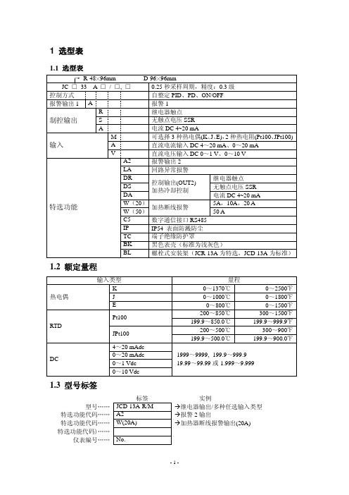
1 选型表
1.1 选型表
→ R-48╳96mm
D-96╳96mm
JC □–33 A □ / □, □
0.25 秒采样周期,精度:0.3 级
控制方式
自整定 PID、PD、ON/OFF
报警输出 1 A
报警 1
R
继电器触点
制控输出
S
无触点电压 SSR
A
电流 DC 4~20 mA
输入
M
可选择 3 种热电偶(K、J、E),2 种热电阻(Pt100、JPt100)
报警 2(A2)动作设定 ·设定报警 2 动作点。 ·设定值为 0 或 0.0 时取消该功能(过程上限和下限报警除外) ·未选择报警 2(A2)动作时无效。 ·设定范围:见表 3.4-1 ·出厂值:0℃
加热器断线报警设定 ·设定加热器断线报警的电流值。 ·当选择 W 特选功能时有效。 ·当主输出关断时,加热器电流值与上次主输出接通时相同。 ·设定值为 0.0 时取消该功能。 考虑到电压波动,推荐设定为加热器额定电流值的约 80%。 ·当报警输出时,自保持功能无效。 ·设定范围:W(5A):0.0~5.0A W(10A):0.0~10.0A
| 方式键
|
符号 P_B
冷却比例带设定 ·设定冷却控制比例带值。(当设定值为 0 或 0.0 时为开/关控制方式)。当 选择 DR,DS 或 DA 特选功能时有效。 ·设定范围:0.0~10.0(与主比例带是比例系数关系) ·出厂值:1.0 倍
| 方式键
|
符号 I
|
方式键
积分时间设定 ·设定积分时间。设定值为 0 时取消该功能。 ·设定范围:0~1000 秒 ·出厂值:200 秒
1.3 型号标签
型号…… 特选功能代码…… 特选功能代码…… (特选功能代码)……
仪表编号……
标签 JCD-13A-R/M A2 W(20A)
No.
实例 à继电器输出/多种任选输入类型 à报警 2 输出 à加热器断线报警输出(20A)
பைடு நூலகம்
-1-
2. 按键与指示灯的名称与功能
(1)PV 显示 用红色 LED 指示过程变量实际值(PV)。 (2)SV 显示 用绿色 LED 指示设定值(SV)或操作变量(MV)。 (3)控制输出或加热输出动作指示灯 当控制输出或加热输出打开时,绿色 LED 指示灯亮。 (4)冷却输出动作指示灯 当冷却输出打开时,黄色 LED 指示灯亮。 (5)加热器断线报警或传感器断线报警动作指示灯 当加热器断线报警输出或传感器断线报警输出开时,红色 LED 指示灯亮。 (当加入了[W]特选功能时,在超量程或欠量程时,红色 LED 指示灯亮。 (6)报警 1(A1)输出动作指示灯 当报警 1(A1)输出打开时,红色 LED 指示灯亮。 (7)串行通讯输出指示灯 当串行通讯输出打开(传送)时,黄色 LED 指示灯闪烁。 (8)报警 2(A2)或回路断线输出动作指示灯 当报警 2(A2)或回路断线输出打开时,红色 LED 指示灯亮。 (9)增加键:增加数值或选择设定值。 (10) 减少键:减少数值或选择设定值。 (11) 方式键:选择设置方式或确认设定值或选择值(按下方式键后设定值或选项才被记