Aerodynamic Design of a Large Horizontal-Axis Wind Turbine
航空发动机专业英语之空气动力学

Introduced how to reduce the impact of emissions on aircraft performance and meet environmental regulations by optimizing exhaust emission design and control technologies.
With the continuous improvement of aircraft performance, the aerodynamic design of aircraft engines is affecting more string requirements, including higher take off and landing speeds, longer flight distances, and more complex flight conditions
Detailed description
Definition and Concepts
Understanding the characteristics and classification of fluids helps to gain a deeper understanding of the working principles of aircraft engines.
Air inlet aerodynamics
Explored the effects of aerodynamic phenomena in combustion chambers on combustion efficiency and emissions, including flame propagation speed, combustion stability, and combustion chamber outlet temperature distribution.
空气动力学基础 安德森 双语
空气动力学基础安德森双语《空气动力学基础:安德森双语》1. 引言空气动力学是研究飞行器在空气中运动的力学原理,它对于航空航天工程领域有着深远的影响。
本文将以经典教材《空气动力学基础》(Fundamentals of Aerodynamics)为依据,结合安德森(John D. Anderson)提出的双语教学理念,深入探讨这一领域的基础知识。
2. 空气动力学基础概述2.1 空气动力学的定义与重要性2.2 安德森对于双语教学的理念解读2.3 《空气动力学基础》这一教材的特点和优势3. 空气动力学基本理论3.1 气体动力学方程及其意义3.2 麦克斯韦方程组在空气动力学中的应用3.3 安德森对于这些基本理论的教学方法4. 飞行器设计中的应用4.1 对于飞行器气动设计的要求4.2 安德森双语教学对于多国家工程师的启发4.3 气动优化在飞行器设计中的应用实例5. 个人观点与总结5.1 对于双语教学的认识与体会5.2 空气动力学基础对于航空航天领域的重要性5.3 对于《空气动力学基础》教材的个人评价在学完《空气动力学基础》这门课之后,我对于这一领域有了更加深入的理解。
安德森提出的双语教学理念不仅让更多的学生能够接触和学习到这一知识,也为多国家的工程师们带来了更多的启发与帮助。
希望未来能够看到更多的优质教材以及教学方法的出现,推动航空航天领域的发展与进步。
空气动力学是航空航天领域的核心学科之一,它研究飞行器在空气中的运动和受力情况。
在现代航空航天工程中,空气动力学的理论基础和应用技术被广泛应用于飞行器的设计、制造和运行中。
本文将继续深入探讨空气动力学基础的相关内容,并结合安德森提出的双语教学理念进行进一步的思考和解析。
在空气动力学基础概述部分,我们已经介绍了空气动力学的基本定义和重要性,以及安德森对于双语教学的理念解读。
空气动力学是研究飞行器在空气中受到的气动力学影响,包括升力、阻力和推进力等。
它对于飞行器的设计、性能和稳定性具有重要的影响。
基于数值模型的气动噪声预测计算方法研究
1气动噪声理论研究的发展随着当今社会工业化进程的飞速发展,气动噪声问题已逐渐成为工业发展中的重要议题。
例如,在航空工业领域,欧美一些发达国家已将航空噪声指标作为适航的关键指标,并针对航空气动噪声问题制定了长期的战略目标和详细的降噪规划。
在我国,机场噪声控制方面也制定了相关规范,对飞机起降噪声提出了明确要求[1]。
历史上,气动声学的早期研究主要集中于涡喷发动机产生的射流噪声问题,这一问题也是该领域的起源和研究的具体起点。
早期人们(甚至现在一些接受非流体背景训练的工程师和研究人员)认为射流噪声问题是流体射流冲击发动机喷管引起的喷管振动发声,并试图通过将射流噪声问题转化为经典声学中的板、壁、壳振动发声问题进行求解。
然而,1952年Lilley 进行了一个简单实验,通过改变流场中的扰动来改变噪声模态,从而否定了这种看法[2]。
同年,Lighthill [3]提出了以自己名字命名的处理喷射噪声问题的声类比理论方程———Lighthill 方程,它建立了声压波动量与流场物理量之间的关联,该方程是研究气动声学的奠基之作,对、气动噪声场分析、气动噪声研究预测、气动噪声装置设计等有着重要的指导作用。
Lighthill 博士是近代气动声学理论的先驱之一,他在气动噪声学上的影响极为深远。
他的理论为自由空间内的喷气噪声等问题的研究,提供了重要的基础,对于没有固体边界的噪声场,该方程依然适用。
他的理论对流体动力噪声的研究和设计产生了深远的影响。
1955年,Curle [4]在Lighthill 的基础上,考虑了静止固体壁面对气流发声的影响,使用基尔霍夫方法对Lighthill 方程进行了改进,推导出了Curle 方程。
1969年,Ffowcs-Williams 和Hawkings [5]在Curle 的理论基础上应用广义函数法,将Curle 的结果进行推广,考虑了运动固体边界对噪声的影响,得到了一个较为普适的方程称为FW-H 方程。
Optimum aerodynamic design for wind turbine blade with a Rankine vortex wake
Optimum aerodynamic design for wind turbine blade with a Rankine vortex wakeDéborah Aline Tavares Dias do Rio Vaz a ,Jerson Rogério Pinheiro Vaz a ,*,AndréLuiz Amarante Mesquita a ,João Tavares Pinho b ,Antonio Cesar Pinho Brasil Junior caUniversidade Federal do Pará,Faculdade de Engenharia Mecânica,Av.Augusto Correa,s/n e Belém,PA 66075-900,Brazil bUniversidade Federal do Pará,Faculdade de Engenharia Elétrica,Av.Augusto Correa,s/n e Belém,PA 66075-900,Brazil cUniversidade de Brasilia,Faculdade de Tecnologia,Departamento de Engenharia Mecânica,Av.L3Norte,Asa Norte,Brasília,Distrito Federal,Cep.70.910-900,Brazila r t i c l e i n f oArticle history:Received 28August 2012Accepted 8December 2012Available online 30January 2013Keywords:Aerodynamic optimization Wind turbine Wind energy BEM modela b s t r a c tThis paper presents a model to optimize the distribution of chord and twist angle of horizontal axis wind turbine blades,taking into account the in fluence of the wake,by using a Rankine vortex.This model is applied to both large and small wind turbines,aiming to improve the aerodynamics of the wind rotor,and particularly useful for the case of wind turbines operating at low tip-speed ratios.The proposed optimization is based on maximizing the power coef ficient,coupled with the general relationship be-tween the axial induction factor in the rotor plane and in the wake.The results show an increase in the chord and a slightly decrease in the twist angle distributions as compared to other classical optimization methods,resulting in an improved aerodynamic shape of the blade.An evaluation of the ef ficiency of wind rotors designed with the proposed model is developed and compared other optimization models in the literature,showing an improvement in the power coef ficient of the wind turbine.Published by Elsevier Ltd.1.IntroductionIn wind turbine design,the maximization of the power coef fi-cient is of fundamental importance in order to optimize the extraction of energy from the wind.This paper addresses the problem of the aerodynamic optimization of a horizontal axis wind turbine rotor,considering the search of optimum shape design of the blade.The optimum design of wind turbine can be achieved from three different approaches that describe the energy conver-sion in the turbine blades.The first one uses the classical Blade Element Model (BEM),which describes this energy conversion by means of force and moment balances in radial sections of the blades (Glauert theory [7,18]).The second approach is based in vortex methods [1],and the last methodology uses the modern fluid flow simulation tools (CFD approach [14]).Presently,an important effort has been devoted to the devel-opment of methodologies of optimization using advanced genetic algorithm and evolutionary computation [1,4,6]coupled to CFD tools [14].Global optimum design can be achieved by the use of those methodologies,where each blade analysis requires a CFDcomputation,which can make this process computationally expensive and thus time-consuming.The high computational costs for these approaches have motivated proposals for modi fied algo-rithms or other alternatives for faster methodologies.A reasonably and fast methodology can be proposed based on the BEM method [18],which is the model most frequently used by scienti fic and wind power industry communities for design and analysis of wind rotors.This method is essentially an integral method,with semi-empirical information from aerodynamics forces in airfoil sections issued from two-dimensional airfoil flow model or experimental data.Thus,complex three-dimensional effects are not accounted for,but the method provides accurate good performance prediction for a large range of wind turbine operation.Besides that,the BEM theory has resulted in good accuracy,allowing the chord and twist distributions to be optimized for maximum power extraction with low computational cost [10,11,13].Currently,BEM is the basis for a great number of optimization methods using the evolutionary computation [1,3].However,optimization methods based on improved BEM models with variational or maximization principles can also provide good solutions,with lower computational cost and advantages in the implementation of the design procedure [8,15].Based on that,this work presents a mathematical model to opti-mize the distributions of chord and twist angle of horizontal axis*Corresponding author.Tel.:þ559181795591.E-mail address:jerson@ufpa.br (J.R.P.Vaz).Contents lists available at SciVerse ScienceDirectRenewable Energyjournal ho me page:www.elsevier.co m/locate/renene0960-1481/$e see front matter Published by Elsevier Ltd./10.1016/j.renene.2012.12.027Renewable Energy 55(2013)296e 304wind turbine blades,taking into account the in fluence of the wake,by using a Rankine vortex model,as proposed by Wilson and Lis-saman [18].This model is applied to both large and small wind turbines,aiming to improve the aerodynamics of the wind rotor.This is particularly useful for the case of wind turbines operating at low tip-speed ratios,as for example the ones with multibladed rotors.The proposed optimization is based on maximizing the local power coef ficient,coupled to the general relationship between the axial induction factor in the rotor plane and in the wake.The results show a modi fication in the chord and twist angle distributions,resulting in an improved aerodynamic shape of the blade.An evaluation of the ef ficiency of wind rotors designed with the pro-posed model is developed and compared with Glauert [7]and Stewart [15]optimization models.The results also show an improvement in the extraction of wind energy due to the change in the aerodynamic shape of the wind blade.2.Mathematical model 2.1.Basic formulationWilson and Lissaman [18]present a one-dimensional mathe-matical model that considers the vortex wake caused by the wind turbine,using a more general form than Glauert ’s model [7]for the calculation of the theoretical power coef ficient.Fig.1illustrates the behavior of the flow in a streamtube and the flow axial velocities.The induced velocities u and u 1in the rotor plane and in the wake,respectively,are written as:&V 0Àv ¼u h ð1Àa ÞV 0V 0Àv 1¼u 1h ð1Àb ÞV 0(1)V 0is the velocity of undisturbed flow,v ¼aV 0,v 1¼bV 0,a and b are the axial induction factors in the rotor plane and in the wake,respectively,and de fined bya ¼V 0Àu 0(2)b ¼V 0Àu 1(3)The power coef ficient,by applying the energy and momentum balance,has the form [17,18,20]:C p ¼b 2ð1Àa Þ2(4)In this expression it is considered that the vortex in the wake behaves as a free vortex.To relate the induction factors to the blade geometry,the model described by Mesquita and Alves [12]isemployed,where from the flow of a streamtube it is possible to derive expressions for the thrust,torque and power for the control volume shown in Fig.1,and using the velocity diagram shown in Fig.2.In this figure L and D are the lift and drag forces,respectively.These relationships are:b 1Àa ¼Bc 4p r C nF sin f (5)b 01þa 0¼Bc 4p r C tF sin f cos f(6)where a 0and b 0are the tangential induction factors at the rotor andfactor at the rotor wake,respectively,and de fined bya 0¼u U (7)b 0¼u 12U(8)U is the angular speed of the wind turbine,w and w 1are therotor and wake angular velocities of the fluid,c is the local chord,r is the radial position in the rotor plane,f is the angle of flow,B is the number of blades,and C n and C t are the coef ficients of the normal and tangential forces (F n and F t )to the rotor plane,given byC n ¼F n 12r W 2cdr ¼C L cos f þC D sin f(9)C t ¼F t 2r W 2cdr ¼C L sin f ÀC D cos f(10)where W is the relative velocity,r is the air density,C l and C d are the lift and drag coef ficients,which are usually obtained from wind tunnel tests or numerical methods [5],and F is the Prandtl tip-loss factor,as described in Ref.[17],which is de fined as the ratio be-tween the bound circulation of all blades and the circulationofFig.1.Simpli fied illustration of the velocities in the rotor plane and in thewake.Fig.2.Velocity diagram for a rotor blade section.D.A.Tavares Dias do Rio Vaz et al./Renewable Energy 55(2013)296e 304297a rotor with an in finite number of blades.It is the most accepted correction employed,and is usually taken as corresponding to a model of the flow for a finite number of blades.Strip theory calculations made with the Prandtl model show good agreement with calculation made through free wake vortex theory and with test data [17].Finally,it is pointed out,according to the analysis performed by Wald [26],in the case of X <2,that the Prandt tip-loss correction does not fit the exact solution of the circulation on the potential flow in a propeller.X is the tip-speed ratio,de fined byX ¼R U V 0(11)where R is the rotor radius.This result suggests that a more detailed investigation for the validity of the use of the Prandt correction in the case of X <2and for turbine flow is necessary.However,this analysis is beyond the scope of this paper and will be considered in future works.Wilson and Lissaman [18]showed that it is possible to establish a general relationship between the axial induction factors a and b from the application of the continuity,momentum and energy equations for the induced velocities in the streamtube shown in Fig.1.Thus,considering the hypothesis that the wake behaves like a free vortex,Wilson and Lissaman [18]demonstrated that the axial induction factor in the rotor plane has a non-linear relationship with the axial inducing factor in the wake for low tip-speed ratios,X ,especially for values X <2,as shown in Fig.3.This relationship is de fined by:a ¼b 2 1Àb 2ð1Àa Þ4X 2ðb Àa Þ!(12)Mesquita and Alves [12]showed that Eq.(12)can be rearranged in the form of a complete cubic equation in b ,where only one of the roots shows a consistent behavior with the physical constraints of the problem.It should be noted that Eq.(12)can also be solved numerically,with good results as shown in Ref.[16].In this case the analytical solution to Eq.(12)isb ¼À12ðS þT ÞÀ13a 1Ài 12ffiffiffi3p ðS ÀT Þ(13)whereS ¼ffiffiffiffiffiffiffiffiffiffiffiffiffiffiffiffiffiffiffiffiffiffiffiffiffiffiffiffiffiffiffiZ þffiffiffiffiffiffiffiffiffiffiffiffiffiffiffiffiffiQ 3þZ 2q 3r (14)T ¼ffiffiffiffiffiffiffiffiffiffiffiffiffiffiffiffiffiffiffiffiffiffiffiffiffiffiffiffiffiffiffiZ ÀffiffiffiffiffiffiffiffiffiffiffiffiffiffiffiffiffiQ 3þZ 2q 3r (15)Q ¼3a 2Àa 219(16)Z ¼9a 1a 2À27a 3À2a 31(17)a 1¼4X 2a À1(18)a 2¼12aX 21Àa (19)a 3¼8a 2X 2a À1(20)2.2.Effect of the wake rotationAs described in some experimental studies found in the liter-ature,for example Whale et al.[21],Ebert and Wood [22]and Hu et al.[9],the flow structure in the wake of a wind rotor is complex with 3D effects and unsteady behavior.However,as already com-mented,the BEM method provides good results for engineering design purpose,and these results are improved when the wake rotation is considered.In order to improve their model,Wilson and Lissaman [18]showed that it is necessary to introduce a correction in Eq.(4),because the free vortex hypothesis causes in finite ve-locities on the wake near the axis of the wind turbine.This fact can be seen in Fig.4,where the power coef ficient tends to high values when X <2.Also,C p can take values greater than 1when X is very small.However,for small values of a and X >2there are physically consistent values for C p .In order to obtain a physically consistent solution,Wilson and Lis-saman [18]proposed the use of a Rankine vortex instead of the irro-tational vortex to represent the wake,which solves the problem of the in finite velocities near the turbine axis.This approach is implemented by the introduction of a parameter N h U =w max in the expression of the power coef ficient,which assumes the following form [18]:C p ¼b ð1Àa Þ2b Àa½2Na þð1ÀN Þb(21)abFig.3.Relation b /a for some values of X .Fig.4.Power coef ficient as a function of axial induction factors a and b .D.A.Tavares Dias do Rio Vaz et al./Renewable Energy 55(2013)296e 304298The parameter N represents the in fluence of the Rankine vortex,and w max is the maximum speed of the vortex wake.The deter-mination of w max is a limitation of this methodology and exper-imental data are needed,as,for example,the experiments carried out by Hu et al.[9],Whale et al.[21]and Ebert and Wood [22].However,unfortunately,in the currently available literature there is a lack of measurements for the hub vortex,particularly for X <2.Figs.5and 6show the behavior of Eq.(21)for N equal to 1and 2,respectively.The value of the maximum power coef ficient of a rotor is heavily in fluenced by the parameter N in the region where X <2.It is observed that for X >2,and consequently b ¼2a ,there is no in fluence of N in the calculation of the theoretical power coef-ficient of an ideal wind turbine,because Eq.(21)reduces to C p ¼4a (1Àa )2,showing that in this case the maximum power coef ficient is 59.26%(Betz ’s limit [2]).Note that for N ¼0,Eq.(21)reduces to Eq.(4).In this work,a sensibility analysis for the parameter N is performed in order to obtain more information on the use of this formulation.For this same correction,other alternatives for the vortex model are possible.A more general model is the Vatistas model given by (Leishaman [23]):v q ¼G r 2p Àr 2n cþr n Á(22)where v q is the tangential velocity component,G is the vortex cir-culation strength,r c is the vortex core radius,n is an arbitraryinteger,and r is the local radial coordinate for the vortex tangential velocity pro file.For n ¼1the Scully vortex is reproduced,for n ¼2one obtains the Bagai-Leishaman vortex model,and for n /N then Vatistas model reduces to the Rankine vortex model.Young [19]has performed an extensive review on existing experimental works available in the literature and,using a kinetic energy conservation approach,concludes that all forms of the Vatistas vortex model,included the Rankine vortex pro file,match reasonably well with the experimental data for the tip vortex.This result is comprehensive because in the model implementation the vortex strength or the core size is often adjusted on a trial and error bases with experimental data.However,as already commented,for the hub vortex the available experimental data are scarce.On the theoretical analysis,this problem was analyzed by some authors after the pioneer work from Wilson and Lissaman [18]in the middle of the 70’s.Wood [24]uses Vatistas vortex with n ¼1and concludes that this model does not have a signi ficant effect on the basic analysis that leads to the Betz limit [2],provided that the core radius of the hub vortex is suf ficiently small and the tip-speedratio is suf ficiently high.For low tip-speed ratios the results become not physically possible with in finite values for the power coef ficient when the tip-speed ratio decreases to zero.Recently,Sørensen and Kuik [25]proposed a model that remedies this problem by including the contribution from the lateral pressure and friction forces in the axial momentum theorem,with result that the power coef ficient never exceeds the Betz limit [2]and tends to zero at zero tip-speed ratio.Since the friction force and pressure on the lateral boundary on the control volume are not known a priori,the authors proposed a model,in which this force is proportional to the wake expansion area and to the tip pressure drop multiplied by a small coef ficient giving the net in fluence of the integrated pressure acting on the lateral boundary of control volume.The determination of this coef ficient is yet open in this methodology.Finally,it is important to analyze the in fluence of the wake rotation in the radial pressure gradient.Sørensen and Kuik [25]showed that the radial pressure gradient in the far wake is given by:v p 1v r 1¼r 11v 2qÀu 1v u 1v r 1(23)where p 1and r 1are the pressure and the local radial coordinate in the far wake,respectively.This gradient has to deliver the cen-tripetal acceleration r v 2q =r 1.This is satis fied when v u 1/v r 1¼0.Consequently,u 1is constant in the fully developed wake.This result allows the determination of a relationship between axial induction factors in the rotor plane and in the wake,respectively.Therefore,according to Sørensen and Kuik [25],applying a combination of the momentum,energy and mass balance equation gives:q ¼b 2ð1Àa Þ2X ðb Àa Þ(24)where q ¼ÀG =ð2p RV 0Þ.In this case,the axial momentum balance is:u V 0¼1Àa ¼q 2þ2Xq 2b(25)Combining Eq.(24)with Eq.(25),one obtains Eq.(12).For the power coef ficient,Sørensen and Kuik [25]showed that:C p ¼2Xq ð1Àa Þ(26)Substituting Eq.(24)in Eq.(26),one obtains Eq.(4).These re-sults,show that the study developed by Sørensen and Kuik [25],about momentum theory at low tip-speed ratio,agree withtheFig.5.Power coef ficient as a function of axial induction factors a and b for N ¼1.Fig.6.Power coef ficient as a function of axial induction factors a and b for N ¼2.D.A.Tavares Dias do Rio Vaz et al./Renewable Energy 55(2013)296e 304299mathematical relations obtained by Wilson e Lissaman [18]for the axial induction factors and power coef ficient,which are used in the present work.2.3.Aerodynamic optimization of wind turbine bladeIn this work the aerodynamic optimization is obtained by maximizing the power coef ficient given by Eq.(21),making d C p /d a ¼0,and resulting in:2d b d a Na 3þ2&2bN Àd b d a ½b ðN À1ÞþN 'a 2þ&2b d dðN À1Þþb 2 1À7N þd b ðN À1Þ!'a þb 21Àd b ðN À1ÞþN !þ2b 3ðN À1Þ¼0(27)Dividing Eq.(27)by the term 2N d b /d a givesa 3þd 1a 2þd 2a þd 3¼0(28)whered 1¼2bN Àd bd a½b ðN À1ÞþN N d b d a(29)d 2¼2b d b d a ðN À1Þþb 2 1À7N þd b d aðN À1Þ!2Nd b d a(30)d 3¼b 21Àd b d aðN À1ÞþN !þ2b 3ðN À1Þ2Nd a(31)where d b /d a is obtained by differentiating Eq.(12).d b¼8a 2X 2Àb È16aX 2Àb Âb ð1Àb Þþ8X 2ÃÉ4a X ÈÂ3a ð1Àa ÞÀ2b ð1Àa Þþ4X ÃÉ(32)Note that Eq.(27)is a complete cubic equation in a ,where only one root presents a physically consistent solution,in a similar way as demonstrated by Mesquita e Alvez [12].The solution of Eq.(27)is given by:a opt ¼À1ðS *þT *ÞÀ1d 1Ài 1ffiffiffi3p ðS *ÀT *Þ(33)whereS *¼ffiffiffiffiffiffiffiffiffiffiffiffiffiffiffiffiffiffiffiffiffiffiffiffiffiffiffiffiffiffiffiffiffiZ *þffiffiffiffiffiffiffiffiffiffiffiffiffiffiffiffiffiQ 3*þZ 2*q 3r (34)T *¼ffiffiffiffiffiffiffiffiffiffiffiffiffiffiffiffiffiffiffiffiffiffiffiffiffiffiffiffiffiffiffiffiffiZ *ÀffiffiffiffiffiffiffiffiffiffiffiffiffiffiffiffiffiQ 3*þZ 2*q 3r (35)Q *¼3d 2Àd 21(36)Z *¼9d 1d 2À27d 3À2d 31(37)Therefore,with the calculated value of it is possible to develop an iterative procedure for the optimum aerodynamic design of wind blades.The optimum chord is calculated using Eq.(5),which in this case can be rewritten as:c opt¼4p rbF sin 2fBC n À1Àa optÁ(38)For the calculation of a 0,the relationship described in Ref.[8]is used,which is de fined as:a 0opt ¼a opttan fx(39)Eq.(39)is valid even for values of X <2,as this relationship is obtained in the rotor plane and not in the wake.Once a 0opt is cal-culated,b 0is described in Mesquita and Alves [12],and Vaz et al.[16],and given by:b 0opt¼ba 0opt a opt(40)The optimum twist angle is obtained from a opt the velocity di-agram shown in Fig.2,by Eq.(41).The velocities diagram wasobtained according to the classical theory of turbomachinery.b opt ¼f opt Àa(41)where f opt is given by Eq.(42)f opt¼tan À1"À1Àa optÁ1þa 0opt x#(42)The iterative procedure for the calculation of optimum chordand twist angle at each section of the blade is detailed as Algorithm .3.Results and discussion3.1.Airfoil dataThe results were obtained using the aerodynamics charac-teristics of the NACA 0012symmetrical airfoil,obtained exper-imentally by Sheldahl and Klimas [27].The NACA 0012is one ofthe most popular symmetrical airfoils,so there are more experimental data available in the literature.Fig.7shows the lift and drag coef ficients for a Reynolds number of 1.6Â105.In this case,the optimizations have been developed for an angleofD.A.Tavares Dias do Rio Vaz et al./Renewable Energy 55(2013)296e 304300attack of 8 .This angle is chosen for maximum C L /C D ,in this case around 44.The NACA 0012airfoil is used here just for the purpose of assessing the behavior of the proposed model,since it is not the objective of the work to evaluate airfoils ef ficiencies.3.2.Results for low tip-speed ratios (X <2)First,to check the behavior of algorithm implementation and its convergence,simulations were performed for small values of X .Fig.8a presents the evolution of the computation of the theoretical power coef ficient (Eq.(21))as a function of the number of itera-tions.The numerical method converges to a number of iterations larger than 25.For a number of iterations less than 25,the power coef ficient tends to exceed the Betz limit [2],and should not be applied.Fig.8b shows that the induction factors in the rotor plane and in the wake do not present a linear behavior for X <2;in other words,b s 2a and b 0s 2a 0.The results were obtained for X ¼1.57.In this case,for N ¼1and N ¼2the power coef ficient tends to less than 59.26%.This effect was expected,because the Rankine vortex causes a reduction in the theoretical power coef ficient for X <2,as shown in Figs.5and 6.For N ¼0and X <2,the Betz limit [2]can be exceeded,as shown in Fig.4,which,according to the actuator disk theory,is not possible.Therefore,the result for N ¼0in Fig.8a,shows the power coef fi-cient to be 59.75%,which is slightly larger than the Betz limit [2],due to the fact that the free vortex hypothesis causes in finite ve-locities on the wake near the axis of the wind turbine [18].In anattempt to correct this problem the Rankine vortex can be employed,as described by Wilson and Lissaman [18]and presented in Figs.5and 6.These results show that the ef ficiency of a wind turbine is heavily in fluenced by wake rotation at low tip-speed ratio operation.Despite the dif ficulty to find detailed experimental results for the vortices hub,some works give very useful information about the vorticity field in the region.These data could provide some indication on the validity of the Rankine vortex assumption and about the parameter N from this model.In order to estimate the parameter N it is necessary to calculate the maximum fluid angular velocity,w max.In the case of the flow behind the wind rotor thevector vorticity,z !is given byz !¼1r v r v q v r À1r v v r v qe !z ¼z z e !z ¼2w z e !z (43)By de finition,the axial component of the vorticity field,z z ,istwice the fluid angular velocity,w z .With the experimental flow velocity data it is possible to estimate the vorticity and,con-sequently,the fluid velocity flow and its maximum,w max.Note that for an axisymmetric flow with free vortex model the vorticity is zero.Recently,Hu et al.[9]carried out an experimental study in order to characterize the dynamic wind loads and evolution of the unsteady vortex and turbulent flow structures in the near wake of a horizontal axis wind turbine model placed in an at-mospheric boundary layer wind tunnel.The measurements wereCLαC DαFig.7.(a)Lift coef ficient and (b)drag coef ficient of the NACA 0012[27].C p Number of iterationsI n d u c t i o n F a c t o rNumber of iterationsFig.8.Convergence of the method:(a)Power coef ficient.(b)Induction factors in the rotor plane and in the wake for the optimized procedure for X ¼1:57and N ¼0.D.A.Tavares Dias do Rio Vaz et al./Renewable Energy 55(2013)296e 304301performed by a PIV (Particle Image Velocimetry)ing these results,it is possible to calculate the parameter N in the Rankine vortex model employed in this work.In Hu ’s experi-ments the diameter of the turbine rotor model was 254mm,which is made of twisted blades,and the mean wind speed at the hub height of the wind turbine model was set to 4.0m/s.In these experiments,it is always reported that the strength of the vor-tices varies with the tip-speed ratio,the maximum value for the axial vortices component was around 50s À1.The experiments were performed for tip-speed ratios of 3.0,3.5,4.0,and 4.5.With these data and using Eq.(43),Table 1shows the estimation of the parameter N as a function of the tip-speed ratio.From this result it can be observed that the parameter N decreases with decreasing tip-speed ratio.Note that the value for maximum axial vorticity is approximated because the results from Hu et al.[9]were presented in the form of color maps and not in a quantitative way.Whale et al.[21]carried out wake velocity and vorticity measurements in an untwisted two-blade wind rotor model with diameter of 175mm using also the PIV technique at tip-speed ratios in the range X ¼3e 8.The experiments were per-formed in a water channel with V 0¼0.25m/s,and the axial vorticity maps were presented in a non-dimensional vorticity de fined byz n ¼4z z d 0(44)where d ¼7.5mm is the spacing of the experimental velocity ing the experimental data obtained by Whale et al.[21],Table 2shows the estimation of the parameter N as a function of the tip-speed ratio.It is veri fied that the parameter N presents the same behavior and the same order of magnitude for both experimental data obtained by Hu et al.[9]and Whale et al.[21].From this analysis it is suggested that the value for the parameter N in the case of X <2could be less than 3.However,these experimental data are not detailed enough for a precise analysis,and more measurements for the vorticity field in the wake hub region are necessary.A second group of simulations is presented to evaluate the per-formance of the model for a small wind turbine with multiple blades,typically used in pumping systems,with 3m diameter and 0.9m hub diameter,constant rotation of 60rpm,average wind speed of 6m/s and 12blades,giving a tip-speed ratio of 1.57.Fig.9shows the chord and twist angle distributions.Note that the aerodynamic shape is different from the results obtained with Glauert [7]and Stewart [15]optimizations models.This occurs due to the fact that the model takes into account the maximum power coef ficient point in the calculation process of the chord and twist angle for any value of X .Table 3shows the power coef ficient and output power for the wind turbines designed under the same operating conditions.In order to verify the performance as a function of the wind speed,Fig.10shows that the power coef ficient and the output power (P )are improved,around 18.54%for a wind speed of 6.5m/s,when compared to the Glauert [7]and Stewart [15]optimizations models (see Fig.10b).The results shown in Table 3can be observed in Fig.10a for X ¼1.57.For the wind speed of 6m/s,for which the wind turbine was designed,the results with the proposed model present better ef ficiency.3.3.Results for high tip-speed ratios (X >2)The proposed model can also be applied for high tip-speed ra-tios.Fig.11shows that the power coef ficient tends to the Betz limit [2]for any value of N .This occurs because the tip-speed ratio is higher than 2,since for X <2the model tends to power coef ficient values lower than the Betz limit.This result shows that Eq.(33)locally maximizes the power coef ficient,and satis fies the Betz [2]condition.The results observed in Fig.11were obtained forTable 1Estimates for N from measurements of Hu et al.[9].X U z z maxw max N 3.094.55025 3.83.5110.25025 4.44.0126.05025 5.04.5141.750255.7Table 2Estimates for N from measurements of Whale et al.[21].X U z n maxz z maxw max N 3.08.60.8 6.7 3.3 2.64.011.40.8 6.7 3.3 3.45.014.30.8 6.7 3.3 4.36.017.10.8 6.7 3.3 5.18.022.90.86.73.36.9r/Rc /Rr/RFig.9.(a)Chord distributions.(b)Twist angle distributions.Table 3Power coef ficient and output power for the designed wind turbines ðX ¼1:57Þ.GlauertStewart N ¼0N ¼1N ¼2C p (%)29.1729.2235.0034.7834.28P (W)278278334331327D.A.Tavares Dias do Rio Vaz et al./Renewable Energy 55(2013)296e 304302。
《飞机总体设计》电子教案2009最新版-南航-余雄庆-620页-单个PDF
飞机设计的过程
• 概念设计 ( Conceptual Design )=技术经济可行性论证 • 初步设计 ( Preliminary Design )=预发展(总体方案论证)
设设 计计 要要 求求
技技
术术
储储
备备
总体设计 =
概念设计 + 初步设计
概念设计
输入
• 设计要求 • 设计规范
目标
• 可行性论证:能否达到设计指标 ? • 获得一个或几个能满足要求的初步方案
工作内容
• 确定全机布局 • 确定主要参数确定 • 选择发动机 • 分系统架构 • 确定部件主要几何参数 • 初步的总体布置 • 方案分析与评估 • 总体参数优化 • 绘制三面图
Integrated Multidisciplinary analysis and optimization
…… aerodynamics
structure performance
conceptual
preliminary
detail
飞机总体设计的重要性
总体设计影响全寿命周期成本的85%!
影 100
2000.
7.
Torenbeek, Synthesis of Subsonic Airplane Design,Delft University Press, 1982.
8. 余雄庆,徐惠民,昂海松,飞机总体设计,航空工业出版社,2000年。
9. 顾诵芬、解思适等编,飞机总体设计,北京航空航天大学出版社,2001年。
95%
响
85%
FundamentalsofAerodynamics第六版课程设计 (2)
Fundamentals of Aerodynamics第六版课程设计介绍本文是基于Anderson的《Fundamentals of Aerodynamics第六版》所设计的课程,旨在提供一个深入学习流体力学和空气动力学的机会,同时帮助学生掌握相关领域的基本知识和技能。
课程大纲第一章:流体力学基础本章介绍流体力学的基本知识,包括流体力学的定义、基本假设、运动学和动力学公式以及基本方程。
本章还将讨论质量、动量、能量守恒定律以及连续性方程等基本概念和原理。
第二章:建立流场方程本章将介绍针对不同情况的流场方程的建立,包括欧拉方程、NSE(Navier-Stokes Equation)等。
第三章:飞行力学基础本章将介绍飞行力学的基本知识,包括飞行器的运动学和动力学方程、空气动力学基本原理以及气动力和控制力等。
第四章:气动力学基础本章将讨论气动力学的基本理论和原理,包括气动力学的定义、不同形状的流体对气动力的影响以及绕流等。
第五章:气动力学数值计算方法本章将介绍用于计算气动力学的数值方法,包括CFD(Computational Fluid Dynamics)等。
第六章:气动力学的应用本章将介绍气动力学的具体应用,包括飞行器设计、气动优化和空气动力学性能评估等。
课程目标课程的主要目标是:•帮助学生掌握流体力学和空气动力学的基本知识和技能;•培养学生的气动力学分析和设计能力;•提供学生探索流体力学和空气动力学不同应用领域的机会;•帮助学生了解气动力学在工程领域的现状和未来发展趋势。
课程要求课程要求学生:•熟练掌握本课程的基础知识和技能;•参加课程中的讨论和实践活动;•独立完成相关课程作业和项目;•提高自己独立思考和解决问题的能力。
课程评估该课程的评估方式包括以下因素:•期末考试占成绩的40%;•课程项目占成绩的30%;•课堂参与占成绩的20%;•平时作业占成绩的10%。
结论本课程旨在提供一个深入学习流体力学和空气动力学的机会,帮助学生掌握相关领域的基本知识和技能,并探索气动力学在工程领域的具体应用。
如何使飞机飞起来英语作文

Airplanes are marvels of engineering that allow us to traverse vast distances in a relatively short amount of time.The concept of making an airplane fly is rooted in a combination of physics,aerodynamics,and engineering principles.Heres an essay on how airplanes achieve flight:The Science of Flight:How Airplanes Take to the SkiesThe ability of an airplane to fly is a testament to human ingenuity and the understanding of natural forces.At the heart of this marvel lies the principle of lift,which is the force that counteracts gravity and allows the aircraft to rise into the air.This essay delves into the intricate processes that enable an airplane to take off,cruise,and land safely.1.The Role of AerodynamicsAerodynamics is the study of how air moves around an object,and in the case of airplanes,it is the science that allows them to fly.The shape and design of an airplanes wings are critical to its ability to generate lift.The wings are typically curved on top and flatter on the bottom,a design known as an airfoil.This shape causes air to move faster over the top of the wing,creating a lower pressure area compared to the higher pressure beneath the wing.This pressure difference results in an upward force,or lift.2.The Importance of ThrustThrust is the force that propels an airplane forward.It is generated by the engines,which can be either turboprops or jet engines.Turboprop engines use a propeller to push air backward,creating a forward thrust.Jet engines operate on the principle of Newtons third law of motion,which states that for every action,there is an equal and opposite reaction. By expelling air at high speed out of the engine,a forward thrust is produced.3.The Balance of Lift and WeightFor an airplane to take off,the lift generated by the wings must be greater than the weight of the aircraft.This is achieved by increasing the angle of attack,which is the angle between the wings chord line and the relative wind.As the airplane accelerates down the runway,the pilot adjusts the control surfaces to increase lift until it overcomes the force of gravity.4.The Control of FlightOnce airborne,an airplane must maintain control throughout its flight.This is managed through the use of control surfaces,which include the ailerons,elevators,and rudder. Ailerons control the roll of the airplane,allowing it to bank left or right.The elevators, located on the horizontal stabilizer,control pitch,enabling the aircraft to climb or descend.The rudder,on the vertical stabilizer,controls yaw,helping the airplane to turn left or right.5.The Role of Air Traffic ControlAir traffic control plays a crucial role in the safe operation of airplanes.Controllers provide pilots with information about weather,air traffic,and other relevant data.They also coordinate the takeoff and landing of aircraft to ensure that they maintain a safe distance from one another.6.The Science of LandingLanding an airplane is a complex process that requires precise control and coordination. As the airplane descends,the pilot reduces the throttle to decrease thrust,and the flaps and slats are extended to increase lift and slow the aircraft down.The pilot must also maintain a stable approach path and touchdown smoothly on the runway.In conclusion,the ability of an airplane to fly is a result of a harmonious blend of science, technology,and human skill.From the moment an airplane leaves the ground to the moment it touches down,a multitude of factors must be considered and controlled to ensure a safe and successful flight.Understanding these principles not only demystifies the art of flying but also highlights the incredible achievements of human innovation and engineering.。
极地破冰船操纵设计需求分析及研究方法综述
1232023年·第3期·总第204期极地破冰船操纵设计需求分析及研究方法综述刘小健1, 3 刘 义2, 3 魏跃峰1, 3(1. 喷水推进技术重点实验室 上海 200011; 2. 上海市船舶工程重点实验室 上海 200011;3. 中国船舶及海洋工程设计研究院 上海 200011)摘 要:…船舶在极地地区航行时的操纵问题远比常规水域复杂,使得船舶在极地的航行十分危险,而目前关于极地破冰船特点及操纵性设计需求等方面的分析研究较少。
该文介绍了与破冰船操纵性相关的风、浪、流、浅水、狭窄水道、低温和能见度等极地环境条件,分析了俄罗斯等国破冰船的分类及特征,总结了吊舱、多桨多舵破冰船操纵装置操纵性标准相关需求。
为满足操纵设计的需要,介绍了破冰船操纵性模型试验、实船试验和数值模拟等操纵性研究方法,提出船-冰相互作用力的计算方法,如经验公式法、有限元法和离散元法等。
通过以上分析与总结,为极地破冰船的操纵性设计提供了思路和参考。
关键词:极地;破冰船;操纵性;研究设计;数值模拟法;试验研究法中图分类号:U661.3………文献标志码:A………DOI :10.19423/ki.31-1561/u.2023.03.123Requirement Analysis and Research Methods of ManeuverabilityDesign for IcebreakerLIU Xiaojian 1, 3 LIU Yi 2, 3 WEI Yuefeng 1, 3(1. Science and T echnology on Water Jet Propulsion Laboratory, Shanghai 200011, China ;…2. Shanghai Key Laboratory on Ship Engineering, Shanghai 200011, China ;…3. Marine Design & Research Institute of China, Shanghai 200011, China)Abstract: The maneuvering of ships sailing in Polar Regions is much more complex than those in conventional waters, imposing hazards on ships sailing in Polar Regions. However, there are currently few analysis and research on the characteristics and maneuverability design requirements of polar icebreakers. This study introduces the polar environment related to the maneuverability of icebreakers, such as the wind, wave and current, shallow water, narrow waterway, low temperature and low visibility. It also analyzes the classification and ship characteristics of the icebreakers in Russia and other countries, and summarizes the relevant requirements of maneuverability standards for maneuvering devices on ice breakers with pod, multi-propeller and multi-rudder. In order to meet the requirement of maneuverability design, it introduces the maneuverability research methods such as the model test, full-scale test and numerical simulation of ice breakers, and the calculation methods for the ship-ice interaction forces such as the empirical formula method, finite element method and discrete element method. The above analysis and summary can provide references for the maneuverability design of icebreakers.Keywords:…polar region; icebreaker; maneuverability; design and research ;numerical simulation; experimental research收稿日期:2022-09-24;修回日期:2022-10-21作者简介:刘小健(1979-),男,博士,研究员。
用于大型地埋管换热器传热分析的绝热圆柱域模型
第52卷第6期2021年6月中南大学学报(自然科学版)Journal of Central South University (Science and Technology)V ol.52No.6Jun.2021用于大型地埋管换热器传热分析的绝热圆柱域模型张方方1,路伟1,朱科1,方肇洪1,于明志1,2(1.山东建筑大学热能工程学院,山东济南,250101;2.山东省绿色建筑协同创新中心,山东济南,250101)摘要:地源热泵空调系统地埋管换热器由大量均匀分布钻孔换热器组成,其长期运行模拟的分析计算任务量大,为此,基于其地下土壤温度场分布特性和传热特性,提出绝热圆柱域模型,采用分离变量和叠加原理的方法得到土壤温度场和钻孔壁温解析解;采用已被广泛接受的有限长线热源模型和工程实测数据验证绝热圆柱域模型,比较不同负荷条件和钻孔数量时,2种模型计算得到的地埋管换热器20a 运行期内钻孔壁温。
研究结果表明:对于大型地埋管换热器,绝热圆柱域模型与有限长线热源模型计算温度结果较一致,且埋管数量越多,误差越小;绝热圆柱域模型尤适用于埋管规模大于30个×30个的大型地源热泵系统的设计计算和分析;绝热圆柱域模型具有计算速度很快的特点,且其计算速度与埋管数量无关;采用绝热圆柱域模型进行埋管数量众多的大型地埋管换热器的设计计算不但具有较高准确度,而且可显著减少计算时间。
关键词:地源热泵;地埋管换热器;传热模型;解析解中图分类号:TU83文献标志码:A开放科学(资源服务)标识码(OSID)文章编号:1672-7207(2021)06-1915-09Adiabatic cylindrical domain model for heat transfer analysis oflarge geothermal heat exchangerZHANG Fangfang 1,LU Wei 1,ZHU Ke 1,FANG Zhaohong 1,YU Mingzhi 1,2(1.School of Thermal Engineering,Shandong Jianzhu University,Jinan 250101,China;2.Co-Innovation Center for Green Building of Shandong Province,Jinan 250101,China)Abstract:The main aim of this paper was to propose a method to cut down the calculation task of the long-term operation simulation of large geothermal heat exchangers(GHEs)of the ground source heat pump air conditioning system,which was composed of a large number of evenly distributed boreholes.Based on the characteristics of收稿日期:2020−12−17;修回日期:2021−02−10基金项目(Foundation item):国家自然科学基金资助项目(41702325);山东省自然科学基金资助项目(ZR2017MEE037);济南市科研带头人工作室项目(2019GXRC066)(Project(41702325)supported by the National Natural Science Foundation of China;Project(ZR2017MEE037)supported by the Natural Science Foundation of Shandong Province;Project(2019GXRC066)supported by the Jinan Scientific Research Leader Studio)通信作者:于明志,博士,教授,从事可再生能源利用及建筑节能技术等研究;E-mail :*******************DOI:10.11817/j.issn.1672-7207.2021.06.021引用格式:张方方,路伟,朱科,等.用于大型地埋管换热器传热分析的绝热圆柱域模型[J].中南大学学报(自然科学版),2021,52(6):1915−1923.Citation:ZHANG Fangfang,LU Wei,ZHU Ke,et al.Adiabatic cylindrical domain model for heat transfer analysis of large geothermal heat exchanger[J].Journal of Central South University(Science and Technology),2021,52(6):1915−1923.第52卷中南大学学报(自然科学版)soil temperature distribution and heat transfer of GHEs,the adiabatic cylindrical domain model(ACDM)was proposed to describe GHEs heat transfer process.With the proposed model,the analytical solutions of soil temperature distribution and boreholes wall temperature were obtained.The widely accepted finite line source model and engineering test data were used to verify ACDM.Two models were used to calculate and compare boreholes wall temperature variation during20a operation under different load conditions and different numbersof boreholes.The results show that the calculation results of temperature of the two models are highly consistent and the consistency increases with the increase of borehole number for large GHEs.ACDM is especially suitablefor simulation and large GHEs with boreholes array larger than30×30.The calculation speed of ACDM is very fast and independent of the number of boreholes,which greatly cuts down the calculation time and is suitable for heat transfer analysis and simulation of large GHEs with large number of boreholes.Key words:ground source heat pump;geothermal heat exchanger;heat transfer model;analytical solution自2010年以来,我国浅层地热能的开发利用年均增长速度约为28%,截止2017年底,中国地源热泵装机容量达2万MW,位居世界第一[1]。
对《Fundamentals of Aerodynamics》第5版的介绍与评价

对《Fundamentals of Aerodynamics》第5版的介绍与评价韩智明(南开大学数学科学学院信息与计算科学专业)张立彬(教育部南开大学外国教材中心)由John D.Anderson,Jr编写的《Fundamentals of Aerodynamics》(《空气动力学基础》)自1984、1991、2001、2007年由McGraw-Hill公司出版前四版以来,已于2011年由该公司再度出版第5版。
本书利用丰富的工程实例讲解了空气动力学基本原理、无粘性不可压缩流、无粘性可压缩流、粘性流体等基本空气动力学理论,内容全面、表述简洁、插图精美、实例典型,是快速学习和掌握空气动力学基本原理的优秀入门教材和参考书。
一、主编简介John D.Anderson,Jr教授为美国马里兰大学教授,他毕生致力于空气动力学理论和实验的研究和教学工作,编写了《Introduction to Flight》、《Fundamentals of Aerodynamics》、《Hypersonic and High Temperature Gas Dynamics》、《Computational Fluid Dynamics:The Basics with Applications》、《Aircraft Performance and Design》等十多部有关空气动力学的优秀著作。
1999年John D.Anderson,Jr教授于马里兰大学退休并被任命为该校的名誉教授,现任美国国家航空航天博物馆空气动力学方面的馆长。
二、教材的总体架构与内容简介《Fundamentals of Aerodynamics》全书共20章,主要包括空气动力学基本原理和方程、无限长和有限长翼型上的不可压缩流、三维不可压缩流、正常激波、斜激波及其扩散、流过喷嘴、散射器和风洞的可压缩流、翼型上亚声速可压缩流的线性理论、非线性超声速流的数值求解理论、超高声速流体元、库埃特流、边界层流、层流边界层、湍流边界层和Navier-Stokes方程等空气动力学问题。
高铁技术的英语作文初一

Highspeed rail,commonly known as bullet trains,has revolutionized the way we travel.It is a testament to the advancements in modern transportation technology.Heres an essay on highspeed rail technology suitable for a junior high school student:The Marvel of Modern Transportation:HighSpeed RailIn the realm of transportation,the advent of highspeed rail has been nothing short of a marvel.It has transformed the way we travel,making long distances seem shorter and more accessible than ever before.The concept of highspeed rail is not new,but its recent advancements have made it a preferred mode of travel for many.Introduction to HighSpeed RailHighspeed rail is a type of rail transport that operates significantly faster than traditional rail traffic.It is characterized by its highspeed train sets and dedicated tracks,which allow for speeds exceeding200kilometers per hour.The technology behind highspeed rail is a combination of aerodynamics,advanced materials,and sophisticated control systems.History and DevelopmentThe idea of highspeed rail was first realized in Japan with the Shinkansen,which began operations in1964.Since then,countries like France,Germany,and China have developed their own highspeed rail networks.The development of highspeed rail has been driven by the need for efficient,environmentally friendly,and comfortable transportation options.Technological InnovationsThe technology behind highspeed rail is continually evolving.Key innovations include:1.Aerodynamics:Highspeed trains are designed with aerodynamic shapes to reduce air resistance,allowing them to travel at high speeds with minimal energy loss.2.Maglev Technology:Some highspeed trains use magnetic levitation,which reduces friction by levitating the train above the tracks,further increasing speed and efficiency.3.Regenerative Braking:This system captures the energy generated during braking andreuses it to power the train,making highspeed rail more energyefficient.4.Advanced Materials:The use of lightweight materials in the construction of highspeed trains reduces the overall weight,allowing for higher speeds and lower energy consumption.5.Control Systems:Sophisticated control systems ensure the safety and precision of highspeed rail operations,including automatic train control and realtime monitoring of train performance.Benefits of HighSpeed RailThe benefits of highspeed rail are numerous and include:1.Time Efficiency:Highspeed rail significantly reduces travel time between cities, making it a viable alternative to air travel for shorter distances.2.Environmental Impact:Compared to other forms of transportation,highspeed rail produces less carbon dioxide and other pollutants,contributing to a cleaner environment.3.Economic Growth:The development of highspeed rail networks stimulates economic growth by improving connectivity between regions,encouraging tourism,and facilitating business activities.4.Safety:Highspeed rail is considered one of the safest modes of transportation,with a low rate of accidents and fatalities.Challenges and the FutureDespite its many advantages,highspeed rail faces challenges such as high initial infrastructure costs,land acquisition issues,and competition from other modes of transportation.However,with ongoing technological advancements and increasing environmental concerns,the future of highspeed rail looks promising.In conclusion,highspeed rail is a remarkable achievement in the field of transportation technology.It offers a fast,efficient,and environmentally friendly way to travel,and as technology continues to advance,we can expect even greater improvements in speed, comfort,and safety.This essay provides a comprehensive overview of highspeed rail technology,its history, technological innovations,benefits,and future prospects,making it suitable for a junior high school students understanding and writing ability.。
《飞机总体设计》电子教案2009最新版-南航-余雄庆-620页-单个PDF

参考教材
1.
L. R. Jenkinson, P. Simpkin, D. Rhodes, Civil Jet Aircraft Design, AIAA Inc, 1999
2.
D.P. Raymer, Aircraft Design: A Conceptual Approach, AIAA Education Series. 1992.
方法与手段
• 统计数据 • 经验公式 • 工程估算公式 • 参数敏感分析 • 地毯图 • 总体分析软件 • 总体参数优化软件
输出
• 初步方案的三面图 • 可行性论证报告 • 详细技术要求与目标
初步设计
输入
• 概念设计结果 • 初始方案的外形CAD模型
目标
• 细化、优化概念设计方案 • 确信方案能达到设计要求,冻结总体外形。
10. 李为吉主编,现代飞机总体综合设计,西北工业大学出版社,2001年。
11. 谢·米·叶格尔[俄]等著,杨景佐、胡传泰等译,《飞机设计》,航空工业出版社,1986年。
12. Nicolai著,赵先宁译,《飞机设计基本原理》,台湾,徐氏基金会,1975年.
飞机设计依据
飞机设计依据
• 飞机设计的基本要求 • 飞机设计规范和适航性条例 • 评价飞机设计方案准则
关于性能指标
• 航程
– 航程对飞机重量的确定有很大影响 – 列出覆盖机场的距离,在此基础上确定航程。
工作内容
• 细化和优化几何外形 - 气动设计、分析与优化
• 总体结构布置 - 结构分析与优化
• 多学科分析与优化 • 完整三面图和外形数模 • 飞机总体布置图
方法与手段
输出
• CAD软件(CATIA)
关于无人机设计的外文专著
关于无人机设计的外文专著Title: Design of Unmanned Aerial Vehicles: A Comprehensive ReviewIntroduction:Unmanned Aerial Vehicles (UAVs), commonly known as drones, have gained significant attention and popularity in recent years. Their versatile applications in various fields, such as military, surveillance, aerial photography, agriculture, and delivery services, have spurred the need for advanced and efficient drone designs. This article aims to provide a comprehensive review of the latest advancements and considerations in the design of UAVs.1. Historical Overview:The article begins by providing a brief historical overview of the development of UAVs. It highlights the milestones in drone technology, from the early remote-controlled prototypes to the sophisticated autonomous systems available today. The evolution of drone designs is discussed, emphasizing the progression from fixed-wing to multi-rotor configurations.2. Aerodynamic Design:The aerodynamic design of UAVs plays a crucial role in their performance and efficiency. This section explores the various factors that influence the aerodynamic characteristics of drones, including wing design, airfoil selection, and control surfaces. It also discusses the impact of aerodynamic considerations on flight stability, agility, and endurance.3. Propulsion Systems:Efficient propulsion systems are essential for achieving optimal flight performance and endurance. This section examines the different types of propulsion systems used in UAVs, including electric motors, internal combustion engines, and hybrid solutions. The advantages and limitations of each system are discussed, along with considerations for power-to-weight ratios, fuel efficiency, and noise reduction.4. Payload Capacity and Integration:UAVs are often used to carry various payloads, such as cameras, sensors, or even cargo. This section delves into the design considerations for payload capacity, including structural integrity, weight distribution, and power requirements. It also discusses the integration of differentsensors and systems, highlighting the challenges and solutions for seamless payload integration.5. Autonomy and Control Systems:The advancement of autonomous technologies has revolutionized the capabilities of UAVs. This section explores the design aspects of autonomy and control systems, including flight control algorithms, navigation systems, and obstacle avoidance mechanisms. The integration of artificial intelligence and machine learning techniques for autonomous decision-making is also discussed.6. Communication and Remote Control:Effective communication systems are vital for UAVs, enabling real-time control and data transmission. This section examines the design considerations for communication systems in drones, including radio frequency selection, data encryption, and signal reliability. It also discusses the integration of remote control interfaces, such as joysticks or mobile applications, for intuitive and precise control.7. Safety and Risk Mitigation:As UAVs become more prevalent, ensuring safety andmitigating risks are paramount. This section addresses the design considerations for safety features, such as redundancy systems, fail-safe mechanisms, and collision avoidance technology. It also discusses the regulations and guidelines imposed by aviation authorities to ensure responsible drone operations.8. Energy Efficiency and Battery Technology:Energy efficiency is essential for extending flight duration and reducing operational costs. This section explores the design aspects of energy-efficient UAVs, including lightweight materials, aerodynamic optimizations, and advanced battery technologies. The challenges and opportunities in improving battery performance and capacity are also discussed.Conclusion:The design of UAVs encompasses various aspects, from aerodynamics and propulsion to autonomy and safety. This comprehensive review highlights the key considerations and challenges in designing efficient and reliable drones. As technology continues to advance, further research and innovation in UAV design will pave the way for new applications and possibilities in the future.。
英语
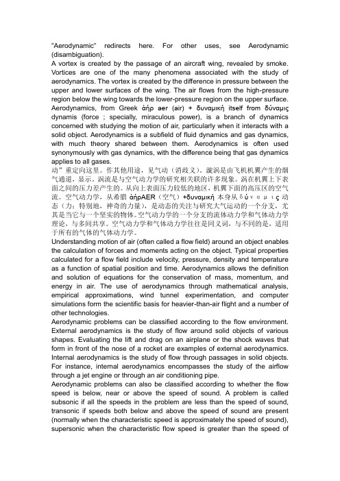
"Aerodynamic" redirects here. For other uses, see Aerodynamic (disambiguation).A vortex is created by the passage of an aircraft wing, revealed by smoke. Vortices are one of the many phenomena associated with the study of aerodynamics. The vortex is created by the difference in pressure between the upper and lower surfaces of the wing. The air flows from the high-pressure region below the wing towards the lower-pressure region on the upper surface. Aerodynamics, from Greek ἀήρ aer (air) + δσναμική itself from δύναμις dynamis (force ; specially, miraculous power), is a branch of dynamics concerned with studying the motion of air, particularly when it interacts with a solid object. Aerodynamics is a subfield of fluid dynamics and gas dynamics, with much theory shared between them. Aerodynamics is often used synonymously with gas dynamics, with the difference being that gas dynamics applies to all gases.动”重定向这里。
空气动力学英文PPT

Aerodynamics is considered with the force acting on objects as they move through the air, such as lift, drag, and thrust, as well as the pressure force acting on the surface of objects It also deals with the flow of gases around objects, including the flow patterns and turbulence
Aerodynamics is also important in the design of cars, trucks, trains, and other vehicles that move through the air It is used to understand the flow of air around these vehicles and to optimize their design for better performance, fuel efficiency, and reduced drag
Friction between the air and the surface of an object moving through it. It is caused by the visibility of air and depends on the surface roughness of the object
Aerodynamics English
目录
Introduction to aerodynamics Basic Theory Principles of aerodynamics Aerodynamic applications Future development and challenges Aerodynamics English terminology
一种卫星天线罩上升过程定常流动数值模拟
第35卷第1期2017年02月空气动力学学报ACTA AERODYNAMICA SINICAVol.35 ,No. 1Feb. ,017文章编号:0258-1825(2017)01-0078-06一种卫星天线罩上升过程定常流动数值模拟徐国武*,杨云军,周伟江(中国航天空气动力技术研究院,北京100074)摘要:在发射的主动上升段,由于天线罩突出卫星密封舱表面,天线罩将承受气流冲刷作用,为了准确设计天线罩抗力学环境,需要对上升段天线罩的受力情况进行详细计算和分析。
根据具体的弹道参数,卫星上升过程中最大动压对应的马赫数约为1. 4,基于此选择动压最大的马赫数段(M a= 1.0〜1.8),采用数值模拟方法详细计算分析了定常状态下天线罩在不同马赫数、不同迎角下的气动力载荷和力矩载荷。
结果表明:随着马赫数的增加,天线罩所承受的气动力载荷和力矩载荷均表现为先增大后减小,最大气动力载荷出现在M a= 1.2,大小约为435. 5N,最大力矩载荷出现在M a= 1. 4,大小约为14. 5Nm;随着迎角的增加,天线罩气动力载荷呈现增大趋势,但增幅较小。
在实际飞行中天线罩的局部或全部已经淹没在火箭弹身的边界层中,因此弹身的存在对天线罩的迎角效应会产生影响。
关键词:天线罩;数值模拟;马赫数;迎角;气动载荷中图分类号:V21 1. 3 文献标识码:A doi:10. 7638/kqdlxxb-2015. 0005Steady numerical simulation of flow over an ascending satellite radomeXu G u o w u*,Yang Y unjun,Zhou Weijiang{China Academ y o f Aerospace Aerodynam ics,Beijing丄00074,China)Abstract:During rocket launching,the radome undergoes air flow s washing protrusion of the s atellite hermetic cabin surface. Inorder to accurately design mechanical environment over the r adom e,the aerodynamic loads of the ascending radome are required to be calculated and analyzed. The maximal dynamic pressure appears at a Mach number of 丄.4accordingto the detailed trajectory parameters. Based on this behavior?the Mach num ber range of M a = 1.0~1.8was chosen for maxim um dynamic pressure^and numerical method was used to calculatethe power load and torque load of the radome at different Mach numbers an attack. The results indicate that the power load and torque load of the radome increase at the be-ginning,and then decrease at ascendingbranch with M a = 1. 0 〜1. 8. The power load achievesm axim um value of about 435. 5 N at M a =1.2, and the torque load achieves m axim um value ofabout 丄4. 5Nm atM a =丄.4. The power force grows slowly as the angle of attack increases. Duringactual flight,local or all of the radome is submerged at the boundary layer of the rocket body,sothat the existence of the rocket body influences the angle of attack effect of the radome.Keyword s:radome; numerical sim ulation;Mach n u m b er;angle of attack; aerodynamic loads0引言天线罩的主要功能是保护罩内天线系统及相关的电子设备免受任何形式的损伤和破坏[-3],由于空气动力学的原因,天线罩系统需具备有利的外形,大 多以流线型为主[4],以减小电磁能量的失真,同时保 证罩内天线性能稳定。
空气动力学家英语
空气动力学家英语Aerodynamics: The Unsung Heroes of Modern EngineeringAerodynamics, a field of study that delves into the intricate interactions between objects and the air that surrounds them, has long been a crucial component of modern engineering. From the sleek designs of high-performance aircraft to the streamlined silhouettes of racing cars, the principles of aerodynamics have been instrumental in pushing the boundaries of technological innovation.At the heart of this field are the unsung heroes – the aerodynamicists, a dedicated group of scientists and engineers who have dedicated their careers to understanding the complexities of fluid dynamics and its application in the real world. These individuals, armed with a deep understanding of physics, mathematics, and computational analysis, work tirelessly to optimize the performance and efficiencyof a wide range of systems, from the smallest components to the largest structures.One of the primary responsibilities of an aerodynamicist is to analyze the flow of air around an object, whether it's a vehicle, a building, or even a simple household item. By using advanced computationalfluid dynamics (CFD) simulations and wind tunnel testing, they can identify areas of high pressure, low pressure, and turbulence, which can have a significant impact on the object's performance and stability.For example, in the design of a high-performance race car, aerodynamicists play a crucial role in ensuring that the vehicle's body and components are shaped in a way that minimizes drag and maximizes downforce. This delicate balance between these two forces can mean the difference between a car that dominates the track and one that struggles to keep up with the competition.Similarly, in the design of aircraft, aerodynamicists work closely with aerospace engineers to create airframes and wing configurations that maximize lift and minimize drag, allowing the aircraft to achieve greater speeds, higher altitudes, and improved fuel efficiency. This knowledge is not only critical for commercial and military aviation but also for the development of cutting-edge technologies, such as unmanned aerial vehicles (UAVs) and hypersonic aircraft.But the impact of aerodynamics extends far beyond the transportation industry. In the field of architecture, aerodynamicists collaborate with designers to create buildings and structures that are not only aesthetically pleasing but also energy-efficient and resilient to environmental forces, such as wind and rain. By understanding theway air flows around a building, they can optimize the placement of windows, doors, and other features to improve natural ventilation and reduce the need for energy-intensive cooling systems.Even in the world of sports, aerodynamics plays a crucial role. Sportswear manufacturers work closely with aerodynamicists to develop clothing and equipment that minimize air resistance and maximize the athlete's performance. From the dimpled surface of a golf ball to the streamlined designs of cycling helmets, the principles of aerodynamics are constantly being applied to push the boundaries of human athletic achievement.Despite the profound impact of their work, aerodynamicists often operate in the background, their contributions overshadowed by the more visible aspects of engineering and design. However, their dedication and expertise are essential to the ongoing progress of technology and the improvement of our daily lives.As we continue to push the boundaries of what is possible, the role of the aerodynamicist will only become more critical. From the development of sustainable energy solutions to the exploration of space, these unsung heroes will be at the forefront of the next generation of technological advancements, using their deep understanding of fluid dynamics to unlock new possibilities and transform the world around us.。
美国登月计划英语听力

美国登月计划英语听力Title: The Epic Journey of America's Lunar Landing ProgramThe journey of America's lunar landing program is not just a technological feat but a remarkable chapter in human history. It's a story of innovation, perseverance, and the unwavering spirit of exploration that has always definedthe American character.In the late 1950s and early 1960s, the world was in the midst of a technological race. The Soviet Union had made significant advancements in space exploration, and America felt the need to catch up. The launch of Sputnik, the first artificial satellite to orbit the Earth, by the Russians in 1957 was a wake-up call for the United States. This event sparked a sense of urgency and determination within the American scientific and political communities to pursue its own ambitious space program.The National Aeronautics and Space Administration (NASA) was established in 1958 with the mission of advancing the nation's capabilities in space science and technology.However, it was the announcement of President John F. Kennedy's bold vision in 1961 that truly set the wheels of the lunar landing program in motion. Kennedy's declaration that America would land a man on the Moon and return him safely to Earth before the end of the decade was a rallying cry that united the nation and propelled NASA's efforts forward.The task ahead was immense. It required the development of new rocket technology, the creation of a spacecraft capable of carrying humans to the Moon, and the formulation of a comprehensive mission plan. NASA drew upon the expertise of thousands of scientists, engineers, and astronauts from across the country, fostering a culture of collaboration and innovation.The Mercury program, the first manned spaceflight program of the United States, laid the foundation for the lunar landing mission. It provided crucial insights into the effects of spaceflight on humans and tested the technology necessary for longer missions. The Gemini program, which followed, furthered these advancements,introducing new techniques such as rendezvous and docking, which would be vital for the lunar landing.However, the Apollo program, named after the Greek godof the sun and poetry, would be the crowning achievement of America's lunar landing efforts. The Apollo missions were complex, each consisting of multiple spacecraft, includinga command module, a service module, and a lunar module. The lunar module, specifically designed for landing on the Moon, was a remarkable feat of engineering.The Apollo missions were not without their challenges. There were numerous setbacks, including technical issues, accidents, and even the tragic loss of astronauts. Yet,each failure served as a learning experience, pushing NASAto refine its technology and procedures.Finally, on July 20, 1969, the world watched in awe as Apollo 11's lunar module, Eagle, touched down on thesurface of the Moon. Neil Armstrong, the commander of the mission, emerged from the lunar module and took those first tentative steps on the lunar surface, declaring, "This is one small step for man, one giant leap for mankind." It wasa momentous occasion, not only for America but for the entire human race.The success of the Apollo missions did not end there. Apollo 12, 14, 15, 16, and 17 followed, each contributing to our understanding of the Moon and its place in the universe. The lunar samples brought back by these missions provided invaluable insights into the Moon's geology and history.In retrospect, the American lunar landing program was more than just a race to the Moon. It was a demonstration of the power of human ingenuity, perseverance, and collaboration. It showed that when faced with seemingly impossible challenges, humans are capable of achieving remarkable things.Today, as we look back on this remarkable era of space exploration, we are reminded of the legacy left by the American lunar landing program. It has not only inspired generations of scientists, engineers, and explorers but has also served as a beacon of hope and inspiration for the entire world.The journey to the Moon may have ended with Apollo, but the spirit of exploration and discovery that it fostered lives on. It continues to drive us forward, pushing the boundaries of what is possible and igniting our imaginations as we embark on new adventures in the vast expanse of space.。
大型飞机增升装置气动机构一体化设计技术进展
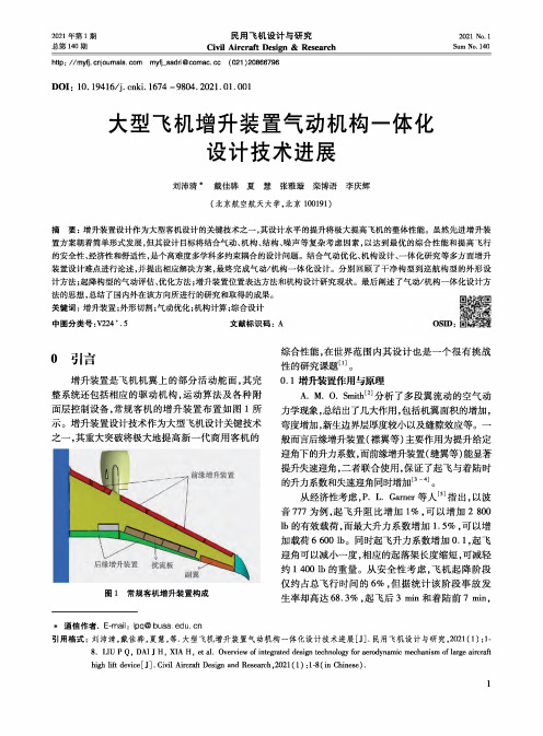
2021年第1期总第140期2021 No.lSum No. 140民用飞机设计与研究Civil Aircraft Design & Researchhttp : //myfj. cnjoumals. com myfj_sadri@comae, cc (021 )20866796DOI : 10.19416/j. enki. 1674 - 9804.2021.01.001大型飞机增升装置气动机构一体化设计技术进展刘沛清*戴佳骅 夏 慧 张雅璇 栾博语 李庆辉(北京航空航天大学,北京100191)摘要:增升装置设计作为大型客机设计的关键技术之一,其设计水平的提升将极大提高飞机的整体性能。
虽然先进增升装 置方案朝着简单形式发展,但其设计目标将结合气动、机构、结构、噪声等复杂考虑因素,以达到最优的综合性能和提高飞行的安全性、经济性和舒适性,是个高难度多学科多约束耦合的设计问题。
结合气动优化、机构设计、一体化研究等多方面增升装置设计难点进行论述,并提出相应解决方案,最终完成气动/机构一体化设计。
分别回顾了干净构型到巡航构型的外形设计方法;起降构型的气动评估、优化方法;增升装置位置表达方法和机构设计研究现状。
最后阐述了气动/机构一体化设计方 法的思想,总结了国内外在该方向所进行的研究和取得的成果。
关键词:增升装置;外形切割;气动优化;机构计算;综合设计中图分类号:V224 + .5 文献标识码:0引言增升装置是飞机机翼上的部分活动舵面,其完整系统还包括相应的驱动机构,运动算法及各种附面层控制设备,常规客机的增升装置布置如图1所示。
增升装置设计技术作为大型飞机设计关键技术 之一,其重大突破将极大地提高新一代商用客机的图1常规客机增升装置构成综合性能,在世界范围内其设计也是一个很有挑战 性的研究课题⑷O0.1增升装置作用与原理A. M. 0. Smith [2]分析了多段翼流动的空气动力学现象,总结出了几大作用,包括机翼面积的增加,弯度增加,新生边界层厚度较小以及缝隙效应等。
航空航天领域的英语作文
航空航天领域的英语作文As I stand at the precipice of the 21st century, gazing up at the vast expanse of the cosmos, I am filled with a sense of wonder and curiosity that has propelled humanity forward for centuries. The aerospace field, a testament to our unyielding spirit of exploration, has not only revolutionized the way we perceive the universe but also transformed the very fabric of our daily lives.The dawn of the Space Age, marked by the launch of Sputnik 1in 1957, ignited a global race that led to monumental achievements. The Apollo 11 mission, which culminated in the first human footprint on the moon in 1969, stands as a crowning jewel of human endeavor. Today, as we reflect onthese milestones, we find ourselves at the cusp of new discoveries that promise to redefine our relationship withthe cosmos.Modern aerospace engineering is a symphony of complex systems, each playing a critical role in the grand design of space exploration. The development of advanced materials that can withstand the harsh conditions of space, the miniaturizationof electronics that enable sophisticated spacecraft, and the use of renewable energy sources for deep space missions are just a few examples of the innovations that are shaping the future of this field.One of the most exciting frontiers in aerospace is theexploration of Mars. With NASA's Perseverance rover and China's Tianwen-1 mission, we are no longer just observing the Red Planet from afar; we are actively engaged in unraveling its mysteries. The search for signs of past or present life on Mars has the potential to answer one of the most profound questions humanity has ever asked: Are we alone in the universe?Commercial space travel is another burgeoning sector that is set to transform our perception of space. Companies like SpaceX and Blue Origin are paving the way for a new era where space is no longer the exclusive domain of government agencies. The prospect of space tourism and the establishment of a lunar base are no longer the stuff of science fiction but are becoming tangible goals that will be pursued in the coming decades.The aerospace industry is also crucial for our understanding of Earth itself. Satellites orbiting our planet provide invaluable data on climate change, weather patterns, and natural disasters. They are the sentinels of our environment, offering a perspective that has led to a greater understanding of the fragility and resilience of our planet.However, the path to the stars is not without its challenges. The risks associated with space travel, the high costs of development, and the ethical considerations of space colonization are issues that must be carefully navigated. International cooperation, sustainable practices, and a commitment to peaceful exploration are essential principles that must guide our journey into the cosmos.In conclusion, the aerospace field is not just a collection of technological advancements; it is a beacon of human ingenuity and our innate desire to explore the unknown. As we continue to push the boundaries of what is possible, we must also remain mindful of our responsibilities as stewards of this endeavor. The stars may be distant, but the future of aerospace is boundless, and it is up to us to ensure that it is a future we can all be proud of.。
- 1、下载文档前请自行甄别文档内容的完整性,平台不提供额外的编辑、内容补充、找答案等附加服务。
- 2、"仅部分预览"的文档,不可在线预览部分如存在完整性等问题,可反馈申请退款(可完整预览的文档不适用该条件!)。
- 3、如文档侵犯您的权益,请联系客服反馈,我们会尽快为您处理(人工客服工作时间:9:00-18:30)。
AAE 415 – Aerodynamic DesignProf. John P. Sullivan Aerodynamic Design of a Large Horizontal-Axis Wind TurbineFinal Project ReportTed Light & Jeffrey RobinsonDecember 19th, 2003I. IntroductionThis report describes the aerodynamic design project undertaken to analyze and optimize the performance of a large horizontal-axis wind turbine. The analysis began with the modeling of an existing wind turbine with documented geometry and performance, and then continued with the variation of several geometric characteristics in order to improve its performance. This process enabled an understanding of some of the fundamentals of wind turbine design. By changing these aerodynamic properties, an improved design was reached.II. BackgroundFor thousands of years, the wind has provided energy to mankind. The wind has allowed ships to sail from place to place, and it has turned windmills which allowed the grinding of grain and the pumping of water. The firstwindmills were primitive andcaught as much air as theycould pointing in only onedirection and using simple,straight, non-aerodynamicblades; nonetheless, they didwhat no other machines haddone before.However, actual powergeneration using windmills didnot occur until the end of the19th century. The advancementof this technology was slow, especially with the rapid industrialization taking place in Europe and the United States. As oil prices fell in the 20th century, wind energy became a less attractive energy source. As such a new technology, wind turbines were expensive to develop and build,and even though the wind itself was free, wind power was still too unreliable to take the place of fossil fuels.Not until the Oil Crisis of the 1970s, when gasoline and other petroleum products were very limited and expensive, did serious interest in wind turbine technology once again emerge. Since then, wind power has become one of the fastest growing energy sources in the world. Constant improvements in aerodynamics, structures, and generators have led to more efficient wind turbines outputting more power than ever.Their use is not only limited to large-scale, commercial energy production. Some small wind turbines are used in homes, for pumping water, or powering satellite and telecommunications dishes. Sometimes they are even used in connection with diesel generators, batteries, and solar power systems. Systems such as these are known as hybrid wind systems and typically are found in remote locations where outside electric power cannot be utilized.3However, it is in these large, commercial utility wind turbines that much technological improvement has taken place. In addition to individual turbine improvements, changes in the wind turbine’s size and the total numb er being used have increased dramatically over recent years. Today’s large wind turbines are sometimes more than a hundred meters in diameter and could be only one of tens or hundreds of wind turbines, all being used together to form a ―wind energy power plant.‖Size is only one design consideration for wind turbines. The number of turbine blades varies between wind machines, along with the blade’s aerodynamic properties, such as taper, twist, and cross-sectional shape. Other advances in wind turbine technology continue today, leading to more powerful and more efficient wind turbines, which will be used to power more of the world in coming years.III. ProcedureThe problem undertaken is the aerodynamic design of a large horizontal-axis wind turbine. To serve as a baseline for comparison purposes, a turbine with established geometry and performance data was found. This turbine was the Mod-2 wind turbine, built by Boeing in the late 1970s. Table 1 gives the geometry and operational data of the turbine, while Figure 1 is a photograph of the Boeing Mod-2 wind turbine.Table 1: Mod-2 Wind Turbine InformationFigure 1: Photograph of the Boeing Mod-2 Wind TurbineThis turbine’s geometry was modeled using CMARC, and then further modified to attain improved performance. The diameter, rotational rate, wind speed, and number of blades were kept constant, however, to keep the comparisons similar. The turbines were also considered to be constant-speed turbines, since our analysis required a constant rotational rate. Since many turbines in use today are constant-speed turbines, this was not an unreasonable assumption.The objective of design improvements was therefore to increase the power output by the wind turbine. The power output of the turbine is given by the simple equation,)Rate Rotational ()axis rotational about Torque ()Power (⋅= (1)The rotational rate was kept constant at 17.5 rpm and the moment about the rotational axis was calculated by the 3D analysis tool CMARC. Research was conducted to formulate ideas on how to improve upon the geometry of the wind turbine. These are discussed below.An expression for the optimal chord length was given by Reference 2. It gives the optimal chord length based upon the number of turbine blades B, their radius R, and the tip speed ratio λ, which is the linear speed of the blade tips divided by the wind speed. The expressions for chord length and tip-speed ratio are given as Equations (2) and (3), respectively.Br R R c 29)/(16λπ=(2) 0/V R Ω=λ(3)Taking five equally spaced control points located at the root, 0.25R , 0.50R , 0.75R , and at the tip, the optimal chord distribution as defined in Equation (2) was calculated; this distribution is given in Table 2.Table 2: Ideal Chord Lengthsr/R Ideal Chord (m)0.0015.000.2511.400.50 5.700.75 3.801.002.85Note that the Equation (2) is not valid for the first control point where r/R = 0, so what was thought to be a reasonable value was substituted.Reference 1 also gives expressions for optimal wind turbines based upon Glauert’s optimal rotor theory. Here the optimal blade layout is given product of the chord c and sectional lift coefficient c l .)31)(1()21()14()(80a a a a c c V B l--⎥⎦⎤⎢⎣⎡--=⎪⎪⎭⎫ ⎝⎛Ωπ (4)In Equation (4) above, a is the axial interference factor, which can be approximated by the following power series as a function of the local speed ratio, x = r Ω/V 0....590494187291081231642+⎪⎪⎭⎫⎝⎛-⎪⎪⎭⎫ ⎝⎛+⎪⎪⎭⎫ ⎝⎛-⎪⎭⎫ ⎝⎛=x x x a (5)These relations were the basis for many of the design changes. The chord and twist values that were used for the design iterations are tabulated below in Table 3 and Table 4, respectively.Table 3: Chord Distributions for Design Iterationsr/R (1)(2)(3)0.0015.0014.0010.000.2511.4011.408.000.50 5.707.00 6.000.75 3.80 3.80 4.001.00 2.85 2.85 2.00Chord Changes (values in meters)Table 4: Twist Distributions for Design IterationsTwist Changes (values in deg from wind axis)r/R(1)(2)(3)0 6.1 6.0 5.50.2566.727.883.50.583.449.5890.7593.871.3901111.693.092Our best turbine, which had the highest power output, included the chord distribution listed as Chord Change (3) above, as well as the twist change listed as Twist Change (1) above. Chord Change (3) was a linear taper approximately over a range of values given by the optimal chord length equations above. Twist Change (1) was found by substituting the same chord distribution into Equation (4) above, and assuming a lift curve slope equal to 2 . One can see that in this twist distribution, the blade’s tip actually twists back beyond the plane of rotation by more than 20 degrees. It seems suspicious that this distribution resulted in the highest calculated power output. This is due to the fact that the blade has a pitch greater than 90 degrees, and it will actually work against the rest of the rotor by lifting in the opposite direction and take power out of the entire wind turbine system. The surprising result obtained from CMARC raised the question as to whether CMARC itself was an accurate analysis tool.IV. Analysis of ResultsBeginning with the Mod-2 baseline model, several modifications were made. With each change, the moment about the rotational axis was computed and used to calculate the power output in kilowatts. This respective power output was then compared to the baseline model in order to establish if the modification was beneficial or not. Table 5 gives the results of all of the design iterations. For each model, the model number is given, with a brief description of the modification, as well as with the power output its relative change from the baseline.Table 5: Design Iteration ResultsMod-2Baseline Model5816---Mod-A Airfoil Changed to NACA 651-0125516-12%Mod-B Airfoil Changed to NACA 65-410617915%Mod-C Airfoil Changed to Althaus AH 93-W-1452551-131%Mod-D Chord Change (1) from Mod-B with no sweep 8914124%Mod-E Chord Change (2) from Mod-B with no sweep 8442105%Mod-F Chord Change (3) from Mod-B with no sweep 787282%Mod-G Chord Change (3) from Mod-B with sweep 9380143%Mod-H Twist Change (1) from Mod-G 10367182%Mod-I Twist Change (2) from Mod-G 784981%Mod-J Twist Change (3) from Mod-G 773577%Mod-2 RatingPublished Power Rating2500Model #DescriptionPower (kW)D from BaselineAfter several modifications to specific elements (i.e., airfoil shape, chord distribution, etc.), the best design was kept and used in later models. An example of this method is shown when several different airfoils were tested in the models Mod-A through Mod-C. Of these options, the NACA 65-410 was chosen to be the best airfoil section, based on power output values in the Table 5. This was then chosen to be the airfoil used in subsequent modifications, and ultimately it was chosen for the final design.After the airfoil shapes were tested and the best kept for further testing, the chord distribution was altered in hopes that a more optimal design could be found. As was discussed in the previous section, the initial chord distribution was obtained using Equation (2). The chord distribution was modified twice more; the distributions are shown in Table 5. Again, the best chord distribution was kept and used for later modifications.Finally, the twist distribution was modified in a similar fashion to that of the airfoil section and the chord distribution. Twisting the blade along the length allowed the angle of attack to be optimized, depending on the relative wind that a given portion of the blade would ―see.‖ Also, by changing the angle of attack, the lift was maximized, increasing the rotational moment and ultimately the power output.Using these modifications, a highly optimized, final wind turbine blade design could be made. This blade design used the NACA 65-410 airfoil section, was approximately 45.7 meters long,with a chord length of 10 meters at the root, tapering linearly to 2 meters at the tip. The blade was highly twisted, with the root directed into the natural wind direction and the tip approximately aligned with the plane of rotation; the blade underwent a major initial change in pitch —60 degrees in pitch in the first 25% of the blade length.This design created a moment about the rotational axis of 2.83 x 10⁶ N-m. Substituting this value into Equation (1), along with the given rotation rate of 17.5 rpm (1.833 rad/sec), the power output was computed to be 10367 kW.The theoretical limit of the maximum amount of power that can be extracted from a wind turbine is known as the Betz limit and is approximately 60%. Given that limit, an analysis is possible to see if the amount of power that can be extracted from the wind has been overpredicted. The kinetic energy in the wind is given by202421V D KE ⎪⎪⎭⎫ ⎝⎛=πρ (6)The power available can then be shown to be equal to the kinetic energy of the wind multiplied by its velocity and the Betz limit.MW s m m m kg V D V D V P 709.4)5.12(4)4.91(225.13.043.04216.03233022020=⎪⎪⎭⎫⎝⎛⋅⋅=⎪⎪⎭⎫ ⎝⎛⋅=⎪⎪⎭⎫ ⎝⎛⎪⎪⎭⎫ ⎝⎛⋅=ππρπρTherefore, from the above calculation, the maximum theoretical output of a wind turbine, using the final design’s given size and wind speed is approximately 4.7 megawatts.(7)A picture of our final turbine is shown in Figure 2. The changing chord length and twist distribution along the blade can easily be seen.Figure 2: Final Wind Turbine Blade DesignFigure 3 is a contour plot the c p distribution of the wind turbine blade near the root. The 3D effects of leakage near the root are evident. The picture also suggests a possible overprediction of c p along the upper surface of the rotor.Figure 3: Cp Distribution for Final Wind Turbine Blade DesignThe results of the animated wake are shown below in Figure 4. Evident is the helix shape as well as the rollup of the vortices near the tip.Figure 4: Wake of Final Wind Turbine Blade DesignV. ConclusionThe aerodynamic design of this large horizontal-axis wind turbine was comprised of several steps, ultimately resulting in a highly optimized final design. The design process began by using technical data from a real-world wind turbine, the Boeing Mod-2, to model a baseline design. From this design, different aerodynamic parameters were varied in order to achieve a more optimal design. Not only did this method allow performance improvements, but it provided an understanding of many of the fundamentals of wind turbine design and qualitative effects of different aerodynamic changes.After each design iteration, the power output was computed and compared to both the baseline model, as well as other previous design iterations. Design changes and modifications continued in hopes of improving the performance even further. Ultimately, a model with the highest power output was chosen as the final design.VI. References1 Eggleston, David M. and Forrest S. Stoddard. Wind Turbine Engineering Design. New York: Van Nostrand Reinhold Company, 1987.2 Piggot, Hugh. Small Wind Turbine Design Notes. Retrived Dec 3, 2003, from/iri/WIND/TECH/WPcourse.3 US Department of Energy. Wind and Hydropower Technologies Program: How Wind Turbines Work. US Department of Energy. Retrived December 18, 2003.</windandhydro/wind_how.html>VII. AppendixA.1 – CMARC Input File for Best Wind Turbine (Mod-H)MODIFIED TURBINE H - modH.in ---> TWIST CHANGE (1)Airfoil = NACA 65-410Cbar = 6.0 [m]R = 45.7 [m]Alpha at Root = 6.1 [deg]Alpha at Tip = 111.6 [deg]--> Twist is non-linearPhi dot = 105 [deg/sec]Vinf = 12.5 [m/s]&BINP2 LSTINP=2, LSTOUT=1, LSTFRQ=1, LENRUN=0, &END&BINP3 LSTGEO=1, LSTNAB=0, LSTWAK=3, LSTCPV=0, LSTJET=0,&END&BINP4 MAXIT=600, SOLRES=0.005, &END&BINP5 NTSTPS=60, DTSTEP=0.08, &END&BINP6 RSYM=1.0, RGPR=0.0, RFF=5.0, RCORE=0.05, &END&BINP7 VINF=12.5, VSOUND=340, UNIT=1, COMPOP=0.0, &END&BINP8 ALDEG=0.0, YAWDEG=0.0, THEDOT=0.0, PSIDOT=0.0, PHIDOT=105, &END&BINP8A PHIMAX=0, THEMAX=0.0, PSIMAX=0.0,WRX=0.0, WRY=0.0 WRZ=0.0 &END&BINP8B DXMAX=0, DYMAX=0.0, DZMAX=0.0,WTX=0, WTY=0.0 WTZ=0.0 &END&BINP9 CBAR=6.0, SREF=274.2, SSPAN=45.7,RMPX=0.00, RMPY=0.00, RMPZ=0.00, &END&BINP10 NORSET=0, NBCHGE=0, NCZONE=0,NCZPAN=0, CZDUB=0.0, VREF=0.0, &END&BINP11 NORPCH=0, NORF=0, NORL=0,NOCF=0, NOCL=0.0, VNORM=0.0, &END&BINP12 KPAN=0, KSIDE=0, NEWNAB=0, NEWSID=0, &END&BINP13 NBLIT=0, &END&ASEM1 ASEMX=0.00, ASEMY=0.00, ASEMZ=0.00,ASCAL=1.00, ATHET=0.00, NODEA=5, &END&COMP1 COMPX=0.0000, COMPY=0.0000, COMPZ= 0.0000,CSCAL=1.000, CTHET=0.0, NODEC=5, &END&PATCH1 IREV=0, IDPAT=1, MAKE=0, KCOMP=1, KASS=1, &END - - - RIGHT BLADE - - -&SECT1 STX=0, STY=0.0, STZ=0, SCALE=10.0, ALF=6.1, THETA=0.0, INMODE=4, TNODS=0, TNPS=0, TINTS=0, &END- - - NACA 65-410 AIRFOIL - - -1.00000 0 0.000000.94971 0 0.003270.89943 0 0.002260.84924 0 -0.000370.79912 0 -0.003930.74910 0 -0.007920.69915 0 -0.012110.64927 0 -0.016210.59947 0 -0.020040.54971 0 -0.023400.50000 0 -0.026060.45032 0 -0.027730.40064 0 -0.028540.35097 0 -0.028630.30128 0 -0.028140.25157 0 -0.027100.20183 0 -0.025470.15202 0 -0.023140.10212 0 -0.019990.07711 0 -0.017910.05203 0 -0.015360.02682 0 -0.011910.01411 0 -0.009440.00893 0 -0.007810.00628 0 -0.006610.00000 0 0.000000.00372 0 0.008610.00607 0 0.010610.01089 0 0.013720.02318 0 0.019350.04797 0 0.028000.07289 0 0.034870.09788 0 0.040670.14798 0 0.050060.19817 0 0.057310.24843 0 0.062900.29872 0 0.067020.34903 0 0.069830.39936 0 0.071380.44968 0 0.071530.50000 0 0.070180.55029 0 0.067200.60053 0 0.062880.65073 0 0.057410.70085 0 0.050990.75090 0 0.043720.80088 0 0.035770.85076 0 0.027290.90057 0 0.018420.95029 0 0.009371.00000 0 0.00000&BPNODE TNODE=3, TNPC=0, TINTC=0, &END&SECT1 STX=0, STY=11.4, STZ=-1.0, SCALE=8.0,ALF=66.7, THETA=0.0, INMODE=0, TNODS=0, TNPS=14, TINTS=3, &END&SECT1 STX=0, STY=22.9, STZ=-2.0, SCALE=6.0,ALF=83.4, THETA=0.0,INMODE=0, TNODS=0, TNPS=14, TINTS=3, &END&SECT1 STX=0, STY=34.3, STZ=-3.0, SCALE=4.0,ALF=93.8, THETA=0.0,INMODE=0, TNODS=0, TNPS=14, TINTS=3, &END&SECT1 STX=0, STY=45.7, STZ=-4.0, SCALE=2.0,ALF=111.6, THETA=0.0,INMODE=0, TNODS=3, TNPS=14, TINTS=3, &END&PATCH1 IREV=0, IDPAT=1, MAKE=1, KCOMP=1, KASS=1, &END- - - RIGHT TIP - - -&PATCH2 ITYP=1, TNODS=5, TNPS=3, TINTS=3, NPTTIP=0, &END&WAKE1 IDWAK=1, IFLXW=0, &END - - - RIGHT WAKE - - -&WAKE2 KWPACH=1, KWSIDE=2, KWLINE=0, KWPAN1=0, KWPAN2=0, NODEW=5, INITIAL=0, &END&ONSTRM NONSL=0 KPSL=0 &END&BLPARAM RN =1640000, VISC =0.00016, NSLBL = 1, &END&VS1 NVOLR=0, NVOLC=0, &END&SLIN1 NSTLIN=0, &END。
