effects cyclone separators
化工设备英文名称大全
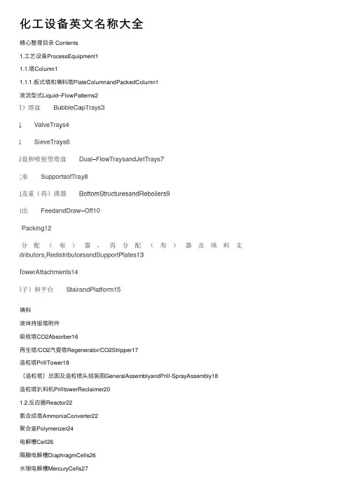
化⼯设备英⽂名称⼤全精⼼整理⽬录 Contents1.⼯艺设备ProcessEquipment11.1.塔Column11.1.1.板式塔和填料塔PlateColumnandPackedColumn1液流型式Liquid–FlowPatterns2填料液体持版塔附件吸收塔CO2Absorber16再⽣塔/CO2汽提塔Regenerator/CO2Stripper17造粒塔PrillTower18(造粒塔)总图及造粒喷头组装图GeneralAssemblyandPrill-SprayAssembly18造粒塔扒料机PrilltowerReclaimer201.2.反应器Reactor22氨合成塔AmmoniaConverter22聚合釜Polymerizer24电解槽Cell26隔膜电解槽DiaphragmCells26⽔银电解槽MercuryCells271.3.浮顶罐1.4.1.5.固定型式管板Tubesheets43管⼦-管板连接,膨胀节及其他零件Tube-TubeSheetJoints,ExpansionJointsandOtherParts44横向折流板和纵向折流板TransverseBafflesandLongitudinalBaffles46套管式换热器和刮⾯式换热器套管式纵向翅⽚换热器DoublePipeLongitudinalFinnedExchanger48板式换热器Plate-TypeExchangers49蒸汽表⾯冷凝器,凝汽器SteamSurfaceCondensers50空冷器,空⽓冷却器Air-CooledHeatExchangers51空冷器的组合形式BayArrangementsofAir-CooledHeatExchanger52管束和头盖(管箱)的典型结构TypicalConstructionofTubeBundlesandHeaders53翅⽚1.6.加热炉管架TubeSupports65转化炉Reformers(ReformingFurnaces)66⼆段转化炉SecondaryReformer67变换炉ShiftConverter68热回收和废热锅炉HeatRecoveryandWasteHeatBoiler69热回收HeatRecovery69燃烧废热锅炉COFiringWasteHeatBoiler70第⼀废热锅炉PrimaryWasteHeatBoiler71第⼆废热锅炉SecondaryWasteHeatBoiler72 ⽕炬FlareStacks73 1.7.混合设备MixingEquipment74搅拌器型式(1)TypesofAgitator(Ⅰ)741.8.1.9.旋风分离器(1)CycloneSeparators(Ⅰ)87旋风分离器(2)CycloneSeparators(Ⅱ)88⽓体洗涤器GasScrubbers90沉降罐,澄清器GravitySettlers(Decanters)92 过滤机Filter93压滤机PressureFilters93叶滤机PressureLeafFilters94袋式过滤器BagFilters95转⿎真空过滤机Rotary-DrumVacuumFilter96离⼼式分离机CentrifugalSeparator97双⿎真空离⼼过滤机Double-BowlVacuumCentrifuge97离⼼机Centrifuges981.10.⽓流(1.11.破沫器及其应⽤ DemisterandItsApplications110破沫⽹的安装和纤维除雾器 InstallationofMeshandFiberMistEliminator111 设备的⽀座和封头SupportsandHeadsofEquipments112⽴式容器的外部保温 ExternalThermalInsulationforVerticalVessel1132.泵 Pump1142.1.各种型式的泵(1)VariousTypesofPump(Ⅰ)114各种型式的泵(2)VariousTypesofPump(Ⅱ)116各种型式的泵(3)VariousTypesofPump(Ⅲ)117各种型式的泵(4)VariousTypesofPump(Ⅳ)1182.2.离⼼泵(1) CentrifugalPump(Ⅰ)119离⼼泵(2) CentrifugalPump(Ⅱ)120离⼼泵(3) CentrifugalPump(Ⅲ)1212.3.2.4.2.5.2.6.2.7.2.8.2.9.3.3.1.3.2.3.3.活塞式压缩机 PistonCompressors1333.4.往复式压缩机 ReciprocatingCompressors1343.5.低密度聚⼄烯(超)⾼压压缩机 HighPressureCompressorforLowDensityPolyethyleneProcess136 3.6.⽔平剖分式离⼼压缩机 HorizontallySplitCentrifugalCompressor1423.7.⿎风机,压⽓机 Blowers1443.8.风机 Fans1463.9.典型的空⽓压缩机装置 TypicalCompressorInstallation1484.输送机和提升机 ConveyorandElevator1494.1.垂直提升(输送)机 VerticalElevator(Conveyor)1494.2.600装置4.3.4.4.吊挂式链输送机和振动输送机 ChainTrolleyConveyorandVibratingConveyor159 4.5.辊⼦输送机 RollerConveyors1624.6.惰轮(托辊)型式 TypesofIdlers1635.破碎和筛分设备 CrushingandScreeningEquipment1665.1.颚式破碎机 Jawcrusher1665.2.颚式冲击破碎机 ImpactJawCrusher1685.3.回转球形破碎机 GyrasphereCrusher1695.4.盘式回转破碎机 TrayTypeGyratoryCrusher1705.5.液压锥形破碎机和冲击式破碎机(叶⽚破碎机5.6.5.7.5.8.5.9.5.10.5.11.5.12.6.6.1.6.2.6.3.6.4.四辊辊压机 Four-RollCalender1847.给料机,称量器和包装机 Feeder,WeighingandBaggingMachine186 7.1.振动给料机 VibratingFeeder1867.2.电振动给料机 ElectricVibratingFeeder1887.3.板式给料机 ApronFeeder1897.4.(粉末)均匀⾃动给料机 SmoothAuto-Feeder1907.5.带式计量秤 DosingBeltWeigher1917.6.定量给料秤 ConstantFeedWeigher1927.7.⾃动装袋系统 AutomaticBaggingSystem1938.汽轮机 SteamTurbine1948.1.汽轮机的分类(1) ClassificationofSteamTurbines(Ⅰ)1948.2.8.3.8.4.8.5.8.6.8.7.8.8.8.9.8.10.8.11.9.锅炉 Boiler2129.1.⽕管锅炉及⽔管锅炉的基本型式 BasicPatternsforFireandWaterTubeBoiler212 9.2.椭圆管板换热器EllipsoidalShellandTubeHeatExchanger2139.3.⽔冷管夹套换热器 CoolingTubesandJacketHeatExchanger2149.4.蒸汽净化及锅筒内件(1) SteamPurificationandDrumInternals(Ⅰ)215蒸汽净化及锅筒内件(2) SteamPurificationandDrumInternals(Ⅱ)216蒸汽净化及锅筒内件(3) SteamPurificationandDrumInternals(Ⅲ)218蒸汽净化及锅筒内件(4) SteamPurificationandDrumInternals(Ⅳ)2199.5.过热器 Superheater2209.6.减温器 Attemperators2219.7.空⽓预热器 AirPreheater2229.8.炉排 Grates2249.9.9.10.9.11.9.12.9.13.10.10.1.10.2.10.3.10.4.10.5.端⾯密封,轴封,轴端连接件 FaceSeals,ShaftSealingsandEndFittings237 10.6.滚⼦轴承,滚柱轴承RollerBearings23810.7.球轴承,滚珠轴承BallBearings23910.8.加油机构 OilingDevices24010.9.紧固件 Fastener24111.配管(管路)和管件 PipingandFitting24511.1.阀杆与阀盖结构 ValveStemandBonnetDesigns24511.2.阀门(1) Valves(Ⅰ)246阀门阀门阀门11.3.11.4.11.5.11.6.11.7.11.8.11.9.11.10.11.11.阀门操纵机构 ValveOperatingMechanisms25911.12.蒸汽疏⽔阀(器)和空⽓疏⽔阀(器) SteamTrapsandAirTraps260 11.13.管道附件 PipeLineFitments26211.14.法兰、法兰密封⾯及垫⽚ Flanges,FlangeFacingsandGaskets264 11.15.填料 Packings26611.16.管件 PipeFitting26711.17.塑料压接管接头 PlasticsCompressionJoints27011.18.预制弯管与膨胀节 FabricatedPipeBendsandExpansionJoints271 11.19.管⼦连接 JointsinTubingandPipe27211.20.11.21.11.22.12.12.1.12.2.12.3.流量测量元件 FlowMeasuringElement28512.5.变送器 Transmitter31112.6.调节(控制)器 Controller31612.7.调节阀 ControlValve31912.8.12.9.⼆氧化碳分析器 CarbonDioxideAnalyzer33212.10.PH计 pHmeters33312.11.粘度测量仪表 ViscosityMeasuringInstruments334 12.12.⽐重仪表 SpecificGravityInstrument336 12.13.速度测量与控制 SpeedMeasurementandControl337 12.14.仪表盘 InstrumentPanels33812.15.温度控制 TemperatureControl34012.16.信号系统AnnunciatorsSystems34112.17.继动器 Relays34412.18.仪表管件及仪表箱 InstrumentationTubeFittingsandHousings34612.19.12.20.12.21.12.22.12.23.12.24.12.25.13.13.1.13.2.变压器 Transformer36513.3.整流器和电池 RectifierandBattery368原电池13.4.13.5.13.6.电磁设备 ElectromagneticApparatus38613.7.电⽓防爆 ElectricalExplosion-proof391 13.8.供电系统 PowerSupplySystem39413.9.14.14.1.起重机械 HoistingMachinery409起重机(2) Cranes(Ⅱ)414起重机(3) Cranes(Ⅲ)41514.2.⼯具 Tools42215.焊接15.1.⾦属焊接 WeldingofMetals43215.2.焊接符号 WeldingSymbols43415.3.保护式电弧焊原理 PrinciplesofShieldedArcWelding43515.4.焊接位置、接头形式及焊接形式 WeldingPositions,TypesofJointsandWelding436 15.5.坡⼝ Grooves437 15.6.坡⼝详图 DetailofGrooves43815.7.焊接缺陷 DefectsofWelding43915.8.填⾓焊,⾓焊 FilletWelding44015.9.⾃动埋弧焊 AutomaticSubmergedArcWelding44115.10.⽓体保护电弧焊 Gas-ShieldedArcWelding44215.11.⾦属极楕性⽓体保护焊 GasMetal-Arcwelding44415.12.⾦属极⽓体保护焊焊枪 ElectrodeGunsofGasMetal-ArcWelding44515.13.15.14.15.15.15.16.15.17.15.18.15.19.15.20.16.16.1.16.2.探孔镜及显微镜 BorescopeandMicroscope45816.3.X射线发⽣管及其线路 X-rayTubeandItsCircuit45916.4.射线照相及电⼦照相 PhotoradiographyandElectroradiography460 16.5.轻便X射线机及透度计 MobileX-rayUnitandPenetrometer46116.6.超声波探伤⽅法及探头 UltrasonicTestMethodsandSearchUnits462 16.7.超声波发射探头及接受探头UltrasonicTransducerandRefraction463。
旋风分离器内三维强旋湍流流动数值模拟的修正压力应变项模型
为:
Π
ij3
=
C1′
ε k
(uk um nk nmδ ij
−
3 2
uiuk n
j nk
−
3 2
u juk ni nk )
k3 2 Cl εd
+ C2′ (Π
km,2 nk nmδ ij
−
(7)
3 2
Π ik,2 n j nk
−
3 2
Π
jk,2 ni nk )
k3 2 Cl εd
其中
k
=
1 2
uiui
总的看来,目前一致认为对旋风分离器内强旋 流动的模拟应当用雷诺应力模型。模拟结果的检验 以时均流场为主,雷诺应力的模拟结果或者缺乏检 验,或者和实验符合较差。本文用作者的实验结果 [10]检验雷诺应力的模拟结果,着重研究了压力应变 项封闭模型,进行了改进,和几种压力应变项模型 进行对比,寻求一种适于强旋流的压力应变项模 型,以便提高雷诺应力预报的合理性。
第 22 卷第 5 期 2005 年 10 月
工程力学 ENGINEERING MECHANICS
Vol.22 No.5 Oct. 2005
文章编号:1000-4750(2005)05-0083-06
旋风分离器内三维强旋湍流流动数值模拟的 修正压力应变项模型
胡王乐元 1,*周力行 1,时铭显 2,张 健 1
Abstract: The Isotropization of Production and Convection plus wall reflection pressure-strain model (IPCM plus wall model) in the Reynolds stress equation is modified for simulating strongly swirling turbulent flows in cyclone separators and is incorporated into the platform of FLUENT 6.0. The three-dimensional turbulent flows in a volute cyclone separator are simulated using modified and standard Isotropization of Production and Convection plus wall reflection models, the Isotropization of Production and Convection models (IPCM models) as well as the Quadratic Pressure-Strain Model (SSG model). Predictions of the time-averaged velocities and Reynolds stresses in the separation space and dust hopper are verified by LDV experimental results. The results indicate that tangential and axial velocities, normal Reynolds stress components, as well as shear stresses predicted using the modified IPCM plus wall model are much better than those obtained using other pressure-strain models.
FLUENT教程--20-27章

20.通用多相流模型(General Multiphase Models)本章讨论了在FLUENT中可用的通用的多相流模型。
第18章提供了多相流模型的简要介绍。
第19章讨论了Lagrangian离散相模型,第21章讲述了FLUENT中的凝固和熔化模型。
20.1选择通用多相流模型(Choosing a General Multiphase Model)20.2VOF模型(Volume of Fluid(VOF)Model)20.3混合模型(Mixture Model)20.4欧拉模型(Eulerian Model)20.5气穴影响(Cavity Effects)20.6设置通用多相流问题(Setting Up a General Multiphase Problem)20.7通用多相流问题求解策略(Solution Strategies for General Multiphase Problems)20.8通用多相流问题后处理(Postprocessing for General Multiphase Problems)20.1选择通用的多相流模型(Choosing a General Multiphase Model)正如在Section 18.4中讨论过的,VOF模型适合于分层的或自由表面流,而mixture和Eulerian 模型适合于流动中有相混合或分离,或者分散相的volume fraction超过10%的情形。
(流动中分散相的volume fraction小于或等于10%时可使用第19章讨论过的离散相模型)。
为了在mixture模型和Eulerian模型之间作出选择,除了Section18.4中详细的指导外,你还应考虑以下几点:★ 如果分散相有着宽广的分布,mixture模型是最可取的。
如果分散相只集中在区域的一部分,你应当使用Eulerian模型。
★ 如果应用于你的系统的相间曳力规律是可利用的(either within FLUENT or through a user-defined function),Eulerian模型通常比mixture模型能给出更精确的结果。
化工原理课件4颗粒的沉降

当作用力等于阻力时,可得离心沉降速度ur
4d ( s )ut2 d 2 ( s ) ut2 ur 相对运动为层流 3r 18 r
4.5 离心沉降(Centrifugal sedimentation )
离 心 力 ut2 / r KC 20.4 r = 0.5m,ut = 10m/s时,分 离 因 数 重力 g
4.4 沉降槽(Settling tank)
4.4 沉降槽(Settling tank)
用于分离悬浮液,连续操作。其生产能力与降尘室一样 与底面积有关,与沉降槽高度无关。 悬浮液中加入电解质、絮凝剂等添加剂有利于絮凝现象 的发生,提高沉降速度;另外,提高悬浮液温度也可提高沉 降速度。 不论是降尘室还是沉降槽,都是利用重力作用的原理达 到分离的目的,对一定的分离体系,分离要求一定,则沉降 速度确定,其分离能力有限,分离直径大于10 μm的颗粒较为 适合,但对小于10 μm颗粒的分离重力沉降无法实现,则改用 离心沉降。
4.6 旋风分离器(Cyclone separators)
(1)结构与工作原理
4.6 旋风分离器(Cyclone separators)
(2)分离性能 旋风分离器能够分离出的颗粒大小是它的主要性能之一。 ① 临界直径dc(Critical diameter) 假设: a、颗粒与气体在旋风分离器内的切线速度ut恒定,与所在位 置无关,且等于进口处的速度ui; b、颗粒沉降过程中所穿过的气流最大厚度等于进口宽度B; c、颗粒与气流的相对运动为层流。 颗粒在旋风分离器中能被完全分离,其沉降时间必须不大 于停留时间
4.6 旋风分离器(Cyclone separators)
② 分离效率 —— 粒级效率、总效率 含尘气体中所有颗粒经分离器后被分离出的质量百分数 η0 ,称为总效率 : c进 口 c出 口 0 100% c进 口
电厂常用英语词汇
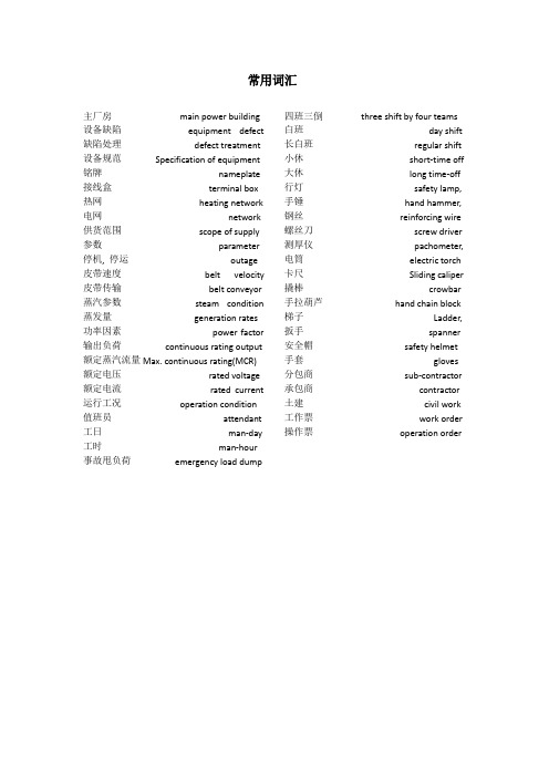
常用词汇主厂房main power building 设备缺陷equipment defect 缺陷处理defect treatment 设备规范Specification of equipment 铭牌nameplate 接线盒terminal box 热网heating network 电网network 供货范围scope of supply 参数parameter 停机,停运outage 皮带速度belt velocity 皮带传输belt conveyor 蒸汽参数steam condition 蒸发量generation rates 功率因素power factor 输出负荷continuous rating output 额定蒸汽流量Max.continuous rating(MCR)额定电压rated voltage 额定电流rated current 运行工况operation condition 值班员attendant 工日man-day 工时man-hour 事故甩负荷emergency load dump 四班三倒three shift by four teams 白班day shift 长白班regular shift 小休short-time off 大休long time-off 行灯safety lamp,手锤hand hammer,钢丝reinforcing wire 螺丝刀screw driver 测厚仪pachometer,电筒electric torch 卡尺Sliding caliper 撬棒crowbar 手拉葫芦hand chain block 梯子Ladder,扳手spanner 安全帽safety helmet 手套gloves 分包商sub-contractor 承包商contractor 土建civil work 工作票work order 操作票operation order锅炉循环流化床(锅炉)the circulating fluidized bed boiler(CFB)固体颗粒soiled particles 底渣bottom ash 循环灰circulating ash 渣场slag yard 磨煤机coal pulverizer 输煤系统coal handing system 送灰器ash conveyer 吹灰器soot blower 除尘器precipitator空气过滤器air filter 石灰石仓limestone silo 给煤机coal feader 返料装置material returning device 布风板air distributor 风嘴air nozzles 风帽air cap 燃烧室combustion chamber 旋风分离器cyclone separator 床料bed material 布袋除尘器bag filter 静电除尘器electrostatic precipitator 密相区dense region 稀相区dilute region 煤仓coal bunker 炉膛furnace 过热器superheater 管束(排)tube bundle 管屏tube platen 再热器reheater 输煤机coal transporter 煤粉锅炉pulverized coal-fired boiler 上升管riser 下降管downcomer 烟囱stack 过滤器strainer 母管main pipe 母线busbar 烟道flue 烟道挡板chimney damper 烟窗帽chimney hood 冷渣机slag cooler 汽包steam drum 流化风室fluidized air chamber 水冷壁water-cooled wall引风机induced draught fan 送风机forced draught fan 一次风primary air 二次风secondary air 排水设备drainage 排污箱blow down tank 排污系统blow down system 烟道净化器flue gas purifier 联箱header(汇集分配工质)蛇形管coil 吊挂管supporting tube鳍片管finned tube,fin tube,gilled tube风门air damper 炉膛容积furnace volume 漏风试验air leakage test膨胀补偿节变电站substation 避雷针lightening rod配电盘distribution boardexpansion joint阻波器line trap阻尼绕组damper winding 污油泵Sump pump卸油泵Oil unloading pump 锅炉附件(锅炉辅助设备)boiler accessories辅助设施auxiliary plant 烟道净化器flue gas purifier净热值Net heating value=低位发热量low point heat value 总热值total heating value=高位发热量high point heat value空气干燥基水分Air dry radicle water空气干燥基弹筒发热量Air dry radicle bomb container heat收到基低位发热量Received radicle low point heat锅炉加沙系统Boiler sand injection system三相感应电机3-phase Induction motor 防爆Explosion-proof循环流化床3跟2连接处有百叶窗(shutter)出来3内有旋风分离器(cyclone separator)1、煤仓;2、炉膛;3、分离器尾部烟道;4、返料器;5、外置式热交换器;6、给煤机;7、冷渣器;8、石灰石仓;9、流化风室;10、汽包;11、对流过热器;12、省煤器;13、空气预热器;14、电除尘器;15、引风机;16、烟囱;17、一次风;18、下二次风;19、上二次风;20、石灰石风机1.Coal bunker2.Furnace3.Backpass of separators4.Material-returning device5.External heat exchanger6.Coal feeder7.Slag cooler8.Limestone silo;9.Fluidized air chamber;10.steam Drum;11.convection superheater12.Economizer;13.Air preheater;14.Electrostatic precipitator(ESP);15.I.D.fan;16.Stack17.Primary air;18.Lower secondary air;19.Upper secondary air;20.Limestone fan;电除尘器electrostatic precipitator(ESP)除尘器布袋除尘器bag filter稀相区dense region炉膛内密相区dilute region1锅炉系统boiler proper system燃烧系统Combustion system蒸汽水系统steam&water system2锅炉辅件系统boiler auxiliary equipment system煤和石灰石系统coal and limestone system烟风系统fuel gas and air system灰处理系统ash handling system锅炉控制系统boiler control system点火系统igniition system3燃烧系统combustion system炉膛旋风分离器furnace cyclone seperator燃烧器布风板burner air distributor煤道点火装置coal duct ignition device风帽返料器air cap material-returning device空气预热器air preheater4汽水系统steam and water system汽包低温过滤器steam drum low temperature filter过热器高温过滤器superheater high temperature filter再热器联箱reheater header省煤器减温器economizer temperature reducer下降管上升管downcomer riser5循环流化床the circulating fluidized bed boiler(CFB)锅炉除尘排渣系统boiler dust clean and slag extracting system 汽水系统烟风及燃烧系统steam-water system flue gas&air and combustion system 输煤系统coal handling system一次风机辅机(风机)二次风机auxiliary system6煤粉炉pulverized fuel boiler炉膛furnace燃烧器burner煤道coal duct空气预热器air preheater7汽包装置steam turbine equipment排污装置blow down device蒸汽清洗装置steam cleaning device加药dosing汽水分离器steam-water separator8锅炉辅助设备boiler auxiliary equipment通风设备draft equipment给煤设备coal feeder给水设备water feeder运煤设备coal transporter除尘设备precipitator除渣设备slag disposal equipment9通风设备draft equipment一次风(送风)primary air(forced air)二次风secondary air引风induced air返料风机material returning fan烟风道flue duct烟囱stack10除渣设备slag disposal equipment除尘器precipitator输灰机ash transporter冷渣机slag cooler输渣机slag transporter11锅炉附件boiler accessories安全门safety valve吹灰器soot blower控制设备control device水位计water level indicator热工仪表thermodynamic instrument汽机轴承bearing 分流器shunt 锅炉补水处理boiler make-up watertreatment断路器circuit breaker 电路electric circuit 分流器shunt trip 电容器capacity 排气压力steam pressure at exhaust 排气消音器exhaust silencer 抽汽系统steam extraction system 主蒸汽及盘路系统main and bypass system 凝结水系统condensate water system 加热器疏水系统heater drains and ventssystem辅助系统auxiliary steam system 润滑油系lubricating oil system 水处理系统water treatment system闭式水循closed circle cooling water system闭式冷却塔系closed cooling Tower system 主蒸汽及再热蒸汽系统main steam andreheat steam system 厂用及仪用压缩空气系统station and instrument air compressed airsystem过热器蒸汽系superheater and steam system主厂房内厂用水系统service water systemin main building 顶轴油系统jacking oil system 密封油系统sealing oil system 轴封油系统gland and steam sealing system 轴封凝汽器gland(steam)condenser轴封供气阀gland sealing valve汽机盘路系统turbine bypass system 汽水取样系统steam water sampling system 液压系统hydraulic system 液压选择阀hydraulic selector 排气消音器exhaust silencer 排气系统exhaust system 高压缸high pressure cylinder 球阀globe valve 闸阀gate valve 疏水阀drain valve 节流阀throttle valve 电磁阀Solenoid valve 截止阀stop valve 主汽门(主蒸汽截止门)main stop valve调节门control valve 逆止门check valve 抽汽调节阀extraction control valve 主汽净化系统main steam cleaning system 挡板调节damper adjustment 自来水raw water 疏水泵drain pump 循环泵circulating pump 灰泵ash pump 胶球泵(rubber)ball pump 胶球清洗系统rubber ball cleaning system 负压negative pressure 支吊架supports and hangers 原料斗raw material bunker 膨胀补偿节expansion joint 空气压缩器air compressor 灰斗ash hooper 风门air damper 沸点boiling temperature 盘车turning gear 盘车投入turning gear start-up 振动报警vibration alarm 振动给煤器vibrating feeder振动除灰装置oscilating-type blower unit 轴外部伸shaft extension 轴位移shaft displacement 遥控remote control自动同步self-timing限制器limiter 蓄压器accumulator空气凝汽器air condenser 鼓风机air blower真空系统vacuum system注油器oil injector除盐水demineralized water 滤油网oil filter排气过滤器air vent filter 机力通风塔induced draught tower热井hot well 机力通风冷却塔forced draught cooling tower减温水attempting water汽蚀cavitation密封垫gasket扩容器flash tank除氧器deaerator旁路bypassvalve汽机冲转run up保安电源系统Emergency power supply system保安断路器safety cutout一主蒸汽系统1郎肯循环锅炉(水加热)汽轮机(水释热)凝结器给水泵锅炉Boiler steam steam turbine condenser feed water pump boiler2主蒸汽系统高低压主蒸汽主汽门高低压缸High pressure main main steam control valve high pressure cylinder二循环水系统(1.凉水塔,2.机力通风塔)induced draught tower循环泵circulating pump胶球泵ball pump三闭式水冷却系统高压给水泵工作油冷却器high pressure feed water pump service oil cooler化学取样冷却器chemistry sampling cooler低压省煤器再循环泵low pressure economizer recirculating pump燃机闭式水空压机gas turbine closed water air compresser冷却水热网循环泵冷却器heading network circulating pump cooler系统燃机发电机空气冷却器gas turbine generator air cooler汽轮发电机冷却器steam turbine generator cooler燃机润滑油冷却器gas turbine lubricating cooler汽机润滑油冷却器steam turbine lubricating cooler膨胀水箱除盐水补水expansion tank demineralized water feed water闭式水泵closed water pump滤网压差大(报警)the differential pressure is too high of filter闭式水换热器旋转滤网closed water heat exchanger rotary strainer循环水泵凝结器机力通风塔胶球泵:清洗脏污四凝结水系统热井凝结水泵杂用母管(减温水)再循环汽机轴封加热器Hot well condensate pump service main pipe(attempting water)main pipe for miscellaneous use(temprature-reduction water)Steam turbine gland seal heater轴封加热器出口调门给水泵高压加热器燃煤炉低压加热器除氧加热器water- feeding pumpoutlet control valve of gland seal heater(feed pump)high pressure heatercoal-fired boiler low pressure heart deaerating heater五油系统交流润滑油泵直流润滑油泵润滑油系统板式换热器排烟风机高压油泵注油器顶轴油泵顶轴油系统滤网模块机械超速保安系统汽机胀差轴向位移轴振瓦振低真空低油压Alternate lubricating oil pump direct lubricating oil pump Lubricating oil system plate exchanger vapor extractorHigh pressure oil pump oil injectorJacking oil pumpJacking oil system filterModulemachine overspeedSecurity system steam turbine differential expansion axial displacementShaft vibration watt vibrationLow vacuum pressure low oil pressure l六辅汽系统辅汽联箱auxiliary steam header轴封供气联箱gland and steam sealing air supply header辅汽联络母管auxiliary steam linking main pipe七轴封系统:轴封加热器gland and steam sealing heater排气风机exhaust fan八抽汽供热系统供热站heat supply station热网循环泵heating network circulating pump 热网疏水泵heating network drain pump旋转隔板rotating diaphragm抽气逆止门(防止倒流)extraction check valve电气1主要设备发电机generator励磁机exciter变压器transformer开关(断路器)switch(circuit breaker)隔离开关(刀闸)disconnecting switch(isolating switch)熔断器(保险)fuse(safety fuse)电动机motor母线(铜排铝排)busbar小母线:(控制回路,信号回路)secondary busbar:控制电缆control loop cable就地local 就地盘表local pannel 就地安装local mounted 运方自动automatically 手动manually 自动-手动开关auto-manual switch 试验trial 解除dismantle 分闸open gate(switch off)合闸switch on 储能power storage 退出quit 退出运行outage 温度自动temperature automatic controller 电源自动加热器power source automatic heat外部联跳(低周减载)进线开关in-coming line switch 进线端子input terminal 启动柴油发电机start-up diesel generator 配电盘switch board 液压油泵hydraulic oil pump 防爆风机explosion-proof fan 调速油泵oil pump of speed adjustmentsystem排水泵drip pump 控制箱control box 油箱净化装置oil purifier 启动准备就绪ready for start up 就地启动direct-on starting(line- start)远程启动remore boot 照明(箱)lighting 电源进线power incoming line电源出线outwards line outgoing feeder?出线端outlet terminal 滤水器water strainer 胶球清洗rubber ball cleaning 汽机保安系统steam turbine security system 中间继电器intermediate relay 压差pressure difference 单侧无(电)压single none-voltage 双侧无压double side none voltage 紧急终止同期emergency stopsynchronization启动同期工作start-up synchronization work 自动校正(同期)automatic correction手动校准manual calibration定子接地stator grounding 转子接地rotator grounding 定子接地保护stator ground protection变压器变压器投运In-service of transformer低压厂用干式变压器(三相环氧浇注式)Low voltage auxiliary dry typetransformer(three-phase epoxy moldedtype)变压器调压装置规定Specification of transformer voltage regulating device 变压器的异常运行及事故处理Accidental treatment and abnormal operation of transformer变压器发生下列异常时允许先联系后停电If any abnormities as followingsoccurred,contact is permitted at firstand then cut power变压器轻瓦斯保护动作Action of transformer light gasprotection变压器差动保护动作Action of transformer differentialprotection高厂变high voltage auxiliary transformer短路阻抗short circuit impedance绕组绝缘等级Winding insulation level接线组别Vector group油枕oil breather杂物,异物sundries变压器外壳transformer casing1所有有关工作票应办理终结并有可投运交待,拆除临时安全措施,恢复常设安全措施,现场清洁。
螺旋输送机外文翻译
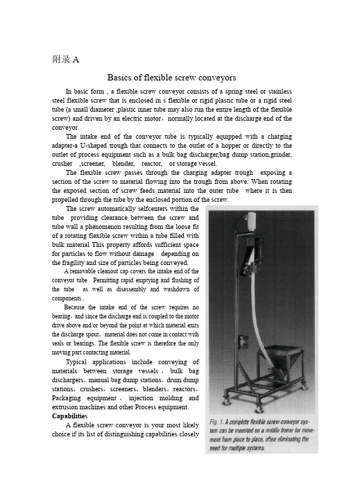
附录ABasics of flexible screw conveyorsIn basic form , a flexible screw conveyor consists of a spring steel or stainless steel flexible screw that is enclosed in s flexible or rigid plastic tube or a rigid steel tube (a small diameter ,plastic inner tube may also run the entire length of the flexible screw) and driven by an electric motor,normally located at the discharge end of the conveyor.The intake end of the conveyor tube is typicallyequipped with a charging adapter-a U-shaped trough that connects to the outlet of a hopper ordirectly to the outlet of process equipment such as a bulk bag discharger,bagdumpstation,grinder, crusher,screener,blender,reactor,or storage vessel.The flexible screw passesthrough the charging adapter trough exposing a section of the screw to material flowing intothe trough from above.When rotating the exposed section of screw feeds material into the outer tube where it is then propelled through the tube by theenclosed portion of the screw.The screw automatically selfcenters within thetube providing clearance between the screw andtube wall a phenomenon resulting from the loose fitofarotating flexible screw withinatube filled withbulk materialThis property affords sufficientspacefor particles to flow without damage depending onthe fragility and size of particlesbeing conveyed.A removable cleanout cap covers the intake end of theconveyor tube Permitting rapid emptying and flushing ofthe tube as well as disassembly and washdownofcomponents.Because the intake end of the screw requires nobearing,and since the discharge end is coupled to the motordrive above and/or beyond the point at which material exitsthe discharge spout,material does not come in contact withseals or bearings.The flexible screw is therefore the onlymoving part contacting material.Typical applications include conveying ofmaterials between storage vessels,bulk bagdischargers,manual bag dump stations,drum dumpstations,crushers,screeners,blenders,reactors,Packaging equipment,injection molding andextrusion machines and other Process equipment.CapabilitiesA flexible screw conveyor is your mostlikelychoice if itslistofdistinguishingcapabilitiesclosely matches that of your requirements,or if an individual capability exclusive toaflexible screw solves an individual problem of key Pare your needs with the following attributes。
化工设备英文名称大全

目录 Contents1. 工艺设备Process Equipment 11.1. 塔Column ['kɒləm]1.1.1. 板式塔和填料塔Plate Column and Packed Column 11.1.1.1. 液流型式Liquid –Flow Patterns 21.1.1.2. 泡罩(帽)塔盘Bubble Cap Trays 31.1.1.3. 浮阀塔盘Valve Trays 41.1.1.4. 筛板塔盘Sieve Trays 61.1.1.5. 穿流式塔盘和喷射型塔盘Dual –Flow Trays and Jet Trays 71.1.1.6. 塔盘的支承Supports of Tray 81.1.1.7. 塔底结构及重(再)沸器Bottom Structures and Reboilers 91.1.1.8. 进料和抽出Feed and Draw –Off 101.1.1.9. 填料Packing 121.1.1.10. 液体分配(布)器,再分配(布)器及填料支持版Liquid Distributors, Redistributors and Support Plates 131.1.1.11. 塔附件 Tower Attachments 141.1.1.12. 楼梯(梯子)和平台Stair and Platform 151.1.2. CO2吸收塔CO2 Absorber 161.1.3. 再生塔/CO2汽提塔Regenerator / CO2 Stripper 171.1.4. 造粒塔Prill Tower 181.1.4.1. (造粒塔)总图及造粒喷头组装图General Assembly and Prill-Spray Assembly 181.1.4.2. 造粒塔扒料机Prill tower Reclaimer 201.2. 反应器Reactor1.2.1. 氨合成塔Ammonia Converter 221.2.2. 聚合釜Polymerizer 241.2.3. 电解槽Cell 261.2.3.1. 隔膜电解槽Diaphragm Cells 261.2.3.2. 水银电解槽Mercury Cells 271.3. 贮罐Storage Tanks 281.3.1. 浮顶罐Floating Roof Tanks 301.3.1.1. 浮顶型式 Floating Roof Types 321.3.1.2. 浮顶罐的密封形式 Seal Types of Floating Roof Tank 34 1.3.2. 内浮顶罐 Covered Floating Roof Tanks 351.3.3. 低温贮罐Refrigerated Storage Tanks 361.4. 蒸发器Evaporators 371.5. 换热器Heat Exchangers1.5.1. 换热器的名称Nomenclature of Heat Exchanger 401.5.1.1. 换热器部件Components of Heat Exchanger 401.5.1.2. 固定端头盖(或管箱),壳体及后端头盖型式Types of Stationary Head, Shell and Rear End Head 421.5.1.3. 管板Tube sheets 431.5.1.4. 管子-管板连接,膨胀节及其他零件Tube-Tube Sheet Joints, Expansion Joints and Other Parts 441.5.1.5. 横向折流板和纵向折流板Transverse Baffles and Longitudinal Baffles 461.5.2. 套管式换热器和刮面式换热器Double-Pipe Heat Exchanger and Scraped-Surface Exchanger 471.5.3. 套管式纵向翅片换热器Double Pipe Longitudinal Finned Exchanger 481.5.4. 板式换热器Plate-Type Exchangers 491.5.5. 蒸汽表面冷凝器,凝汽器Steam Surface Condensers 50 1.5.6. 空冷器,空气冷却器Air-Cooled Heat Exchangers1.5.6.1. 空冷器的组合形式Bay Arrangements of Air-Cooled Heat Exchanger 521.5.6.2. 管束和头盖(管箱)的典型结构Typical Construction of Tube Bundles and Headers 531.5.6.3. 空冷器的驱动装置Drive Arrangements for Air Cooler 541.5.6.4. 翅片Fins 551.5.6.5. 空冷器的温度控制Temperature Control of Air Cooler 561.5.7. 冷却塔,凉水塔(1)Cooling Towers(Ⅰ) 57冷却塔,凉水塔(2)Cooling Towers(Ⅱ) 581.6. 工业炉Furnace1.6.1. 管式加热炉Pipe Heater 601.6.1.1. 管式加热炉型式Types of pipe Heaters (pipe Still Heater) 601.6.1.2. 加热炉Heaters1.1.6.3. 燃烧器,烧嘴Burners 631.1.6.4. 炉管,联管箱和回弯头Tube, Headers and Return Bends 641.1.6.5. 管架Tube Supports 651.6.2. 转化炉Reformers (Reforming Furnaces) 661.6.3. 二段转化炉Secondary Reformer 671.6.4. 变换炉Shift Converter 681.6.5. 热回收和废热锅炉Heat Recovery and Waste Heat Boiler 691.6.5.1. 热回收Heat Recovery 691.6.5.2. CO燃烧废热锅炉CO Firing Waste Heat Boiler 70 1.6.5.3. 第一废热锅炉Primary Waste Heat Boiler 711.6.5.4. 第二废热锅炉Secondary Waste Heat Boiler 72 1.6.6. 火炬Flare Stacks 731.7. 混合设备Mixing Equipment 741.7.1. 搅拌器型式(1)Types of Agitator(Ⅰ) 74搅拌器型式(2)Types of Agitator(Ⅱ) 761.7.2. 混合(搅拌)槽Mixing Tanks 771.7.3. 管道混合器Line Mixers (Flow Mixers) 781.7.4. 静止混合器Static Mixers 791.7.5. 膏状物料及粘性物料混(拌)合设备Paste and Viscous-Material Mixing Equipments 801.7.6. 固体混合机械Solids Mixing Machines 821.7.7. 双螺杆连续混合机Double Screw Continuous Mixer 83 1.8. 萃取器Extractors 841.8.1. 连续萃取设备,连续抽提设备Continuous Contact (Differential Contact) Equipments 841.8.2. 浸提设备Leaching Equipments 861.9. 旋风分离器、沉清器、过滤器和离心机Cyclone, Decanter, Filter and Centrifuge 871.9.1. 旋风分离器(1)Cyclone Separators (Ⅰ) 87旋风分离器(2)Cyclone Separators (Ⅱ) 881.9.2. 气体洗涤器Gas Scrubbers 901.9.3. 沉降罐,澄清器Gravity Settlers (Decanters) 921.9.4. 过滤机Filter 931.9.4.1 压滤机Pressure Filters 931.9.4.2 叶滤机Pressure Leaf Filters 941.9.4.3 袋式过滤器Bag Filters 951.9.4.4 转鼓真空过滤机Rotary-Drum Vacuum Filter 961.9.5. 离心式分离机Centrifugal Separator 971.9.5.1. 双鼓真空离心过滤机Double-Bowl Vacuum Centrifuge 971.9.5.2. 离心机Centrifuges 981.9.5.3. 静止叶片型离心式分离器Stationary Vane Type Centrifugal Separators 1001.10. 干燥器Dryers 1011.10.1. 间接干燥器Indirect Dryers 1011.10.2. 直接干燥器Direct Dryers 1021.10.3. 喷雾干燥器Spray Dryers 1041.10.3.1. 雾化喷头,喷雾嘴,雾化器Spray Nozzles (Atomizers) 1051.10.4. 气流(气动)输送干燥器Pneumatic Conveyor Dryers 106 1.11. 其他Miscellaneous 1071.11.1. 石油炼制中的流化过程Fluidization Processes in Petroleum Refinery 1071.11.1.1. 流态化Fluidization 1081.11.1.2. 流化床分布器Distributors for Fluidized Bed 1091.11.2. 破沫器及其应用Demister and Its Applications 1101.11.2.1. 破沫网的安装和纤维除雾器Installation of Mesh and Fiber Mist Eliminator 1111.11.3. 设备的支座和封头Supports and Heads of Equipments 1121.11.4. 立式容器的外部保温External Thermal Insulation for Vertical Vessel 1132. 泵Pump2.1. 各种型式的泵(1) Various Types of Pump (Ⅰ) 114各种型式的泵(2) Various Types of Pump (Ⅱ) 116各种型式的泵(3) Various Types of Pump (Ⅲ) 117各种型式的泵(4) Various Types of Pump (Ⅳ) 1182.2. 离心泵(1) Centrifugal Pump(Ⅰ) 119离心泵(2) Centrifugal Pump(Ⅱ) 120离心泵(3) Centrifugal Pump(Ⅲ) 1212.3. 管道泵Inline Pump 1222.4. 双作用蒸汽往复泵Duplex Acting Steam-Driven Reciprocating Pump 1232.5. 双作用活塞式往复泵Double Action Reciprocating Pump, Bucket Type 1242.6. 混流泵 Mixed-Flow Pump 1262.7. 计量泵Metering Pumps 1272.8. 喷射泵Jet Pumps 1282.9. 喷射装置Ejector Units 1292.9.1. 喷射器的结构Ejector Structures 1303. 压缩机、鼓风机和风机Compressors Blowers and Fans3.1. 螺杆压缩机Screw Compressors 1313.2. 旋转式螺杆压缩机Rotary Helical Screw Compressors 132 3.3. 活塞式压缩机Piston Compressors 1333.4. 往复式压缩机Reciprocating Compressors 1343.5. 低密度聚乙烯(超)高压压缩机High Pressure Compressor for Low Density Polyethylene Process 1363.5.1. 高压气缸和中心型组合阀High-Pressure Cylinder and Central Valve 1383.5.2. 卸荷阀并及其他阀Unloading Valve and Other Valves 1403.6. 水平剖分式离心压缩机Horizontally Split Centrifugal Compressor 1423.7. 鼓风机,压气机Blowers 1443.8. 风机Fans 1463.9. 典型的空气压缩机装置Typical Compressor Installation 1484. 输送机和提升机 Conveyor and Elevator 1494.1. 垂直提升(输送)机Vertical Elevator (Conveyor) 1494.1.1. 斗式提升机Bucket Elevator 1494.1.2. 垂直提升输送机和箱类提升机Vertical Rising Conveyor and Case Elevator 1504.1.3. 双带提升机Twin Riser 1514.2. 带式输送机Band (Belt) Conveyor 1524.2.1. 带式输送机示意图Band Conveyor Sketch 1524.2.2. 输送机系统Conveyor Systems 1534.2.3. 带式输送机Band Conveyor 1544.2.4. 中心距超过600英尺的单轮传动带式输送机用的张紧装置Take-up Unit for Single Drum Drive Belt Conveyor Exceeding 600 Feet Centers 1554.2.5. 双轮传动带式输送机的张紧装置Take-up Unit for Dual Drum Drive Belt Conveyor 1564.2.6. 拼装式皮带运输机和移动式皮带运输机Pre-built Sectional Belt Conveyor and Mobile Belt Conveyor 1574.3. 螺旋输送机Screw Conveyor 1584.4. 吊挂式链输送机和振动输送机Chain Trolley Conveyor and Vibrating Conveyor 1594.4.1. 吊挂式链输送机部件Units of Chain Trolley Conveyor 160 4.5. 辊子输送机Roller Conveyors 1624.6. 惰轮(托辊)型式Types of Idlers 1634.6.1. 托辊(惰轮)结构Construction of Iders 1645. 破碎和筛分设备Crushing and Screening Equipment 1665.1. 颚式破碎机Jaw crusher 1665.2. 颚式冲击破碎机Impact Jaw Crusher 1685.3. 回转球形破碎机Gyrasphere Crusher 1695.4. 盘式回转破碎机Tray Type Gyratory Crusher 1705.5. 液压锥形破碎机和冲击式破碎机(叶片破碎机) Hydraulic Cone Crusher and Impact Crusher (Impeller Breaker) 1725.6. 辊子粉碎机Roller Mill 1735.7. 双轴锤击破碎机Double Shaft Hammer Mill 1745.8. 球磨机Ball Mill 1765.9. 干燥粉磨机Dryer-Pulveriser 1775.10. 返混设备布置Layout of Back mixing Equipment 1785.11. 振动筛Vibrating Screen 1795.12. 分级机Classifiers 1806. 塑料和橡胶加工成型机械 Forming Machine For Plastics and Rubber 1816.1. 挤压机Extruder 1816.2. 螺杆注塑机Screw Injection Molding Machine 1826.3. 聚氯乙烯辊压机生产线Calender Line for PVC Production 1836.4. 四辊辊压机Four-Roll Calender 1847. 给料机,称量器和包装机Feeder, Weighing and Bagging Machine 1867.1. 振动给料机Vibrating Feeder 1867.2. 电振动给料机Electric Vibrating Feeder 1887.3. 板式给料机Apron Feeder 1897.4. (粉末)均匀自动给料机Smooth Auto-Feeder 1907.5. 带式计量秤Dosing Belt Weigher 1917.6. 定量给料秤Constant Feed Weigher 1927.7. 自动装袋系统 Automatic Bagging System 1938. 汽轮机Steam Turbine 1948.1. 汽轮机的分类(1) Classification of Steam Turbines (Ⅰ) 194 汽轮机的分类(2) Classification of Steam Turbines (Ⅱ) 1968.2. 汽轮机的循环Steam Turbine Cycles 1978.3. 汽轮机供汽方式 Methods of Steam Supply to a Turbine 198 8.4. 单级汽轮机Single Stage Steam Turbine 1998.5. 冲动式汽轮机Impulse Turbines 2008.6. 汽轮机轴封Turbine Glands and Gland Sealings 2028.7. 汽轮机的润滑Lubrication of Steam Turbine 2048.8. 汽轮机调速器及调速Governors and Governing of Steam Turbine 2068.9. 汽轮机调速器 Turbine Governor 2088.10. 超速脱扣装置(保安器) Overspeed Tripping Device 2108.11. 汽轮机的安装 Installation of Steam Turbine 2119. 锅炉 Boiler 2129.1. 火管锅炉及水管锅炉的基本型式 Basic Patterns for Fire and Water Tube Boiler 2129.2. 椭圆管板换热器 Ellipsoidal Shell and Tube Heat Exchanger2139.3. 水冷管夹套换热器 Cooling Tubes and Jacket Heat Exchanger 2149.4. 蒸汽净化及锅筒内件(1) Steam Purification and Drum Internals (Ⅰ) 215蒸汽净化及锅筒内件(2) Steam Purification and Drum Internals (Ⅱ) 216蒸汽净化及锅筒内件(3) Steam Purification and Drum Internals (Ⅲ) 218蒸汽净化及锅筒内件(4) Steam Purification and Drum Internals (Ⅳ) 2199.5. 过热器 Superheater 2209.6. 减温器 Attemperators 2219.7. 空气预热器 Air Preheater 2229.8. 炉排 Grates 2249.9. 下饲炉排 Underfeed Stoker 2259.10. 喷燃器,燃烧器 Burners 2269.11. 省煤器 Economizer 2289.12. 抛煤机 Spreader Feeders 2299.13. 磨煤机 Pulverizers 23010. 机械零件 Machine Element 23110.1. 万向节 FUniversal Joints 23110.2. 联轴器 Couplings 23210.3. 液力联轴器(1) Fluid Couplings (Ⅰ) 234液力联轴器(2) Fluid Couplings (Ⅱ) 23510.4. 轴颈密封,圆周密封 Circumferential Seals 23610.5. 端面密封,轴封,轴端连接件 Face Seals, Shaft Sealings and End Fittings 23710.6. 滚子轴承,滚柱轴承 Roller Bearings 23810.7. 球轴承,滚珠轴承Ball Bearings 23910.8. 加油机构 Oiling Devices 24010.9. 紧固件 Fastener 24110.9.1. 螺栓和双头螺柱 Bolts and Studs (stud bolts) 24110.9.2. 螺钉的头部和端部型式 Heads and Points of Screw 242 10.9.3. 螺母 Nuts 24310.9.4. 非螺纹紧固件 Non-threaded Fasteners 24411. 配管(管路)和管件 Piping and Fitting 24511.1. 阀杆与阀盖结构 Valve Stem and Bonnet Designs 24511.2. 阀门(1) Valves(Ⅰ) 246阀门(2) Valves(Ⅱ) 248阀门(3) Valves(Ⅲ) 249阀门(4) Valves(Ⅳ) 25011.3. 闸阀 Gate Valve 25111.4. 截止阀 Globe Valve 25211.5. 球阀 Ball Valve 25311.6. 止回阀 Check Valve 25411.7. 弹簧安全泄压阀 Spring Safety-Relief Valve 25511.8. 液面控制浮球阀 Pilot Operated Ball Float Valve 25611.9. 波纹管密封闸门阀 Bellows Sealed Gate Valve 25711.10. 热膨胀阀 Thermo Expansion Valve 25811.11. 阀门操纵机构 Valve Operating Mechanisms 25911.12. 蒸汽疏水阀(器)和空气疏水阀(器) Steam Traps and Air Traps 26011.13. 管道附件 Pipe Line Fitments 26211.14. 法兰、法兰密封面及垫片 Flanges, Flange Facings and Gaskets 26411.15. 填料 Packings 26611.16. 管件 Pipe Fitting 26711.16.1. 法兰管件 Flanged Fittings 26711.16.2. 螺纹管件 Threaded Fittings 26811.16.3. 钢焊接管件 Steel-Welding Fittings 26911.17. 塑料压接管接头 Plastics Compression Joints 27011.18. 预制弯管与膨胀节 Fabricated Pipe Bends and Expansion Joints 27111.19. 管子连接 Joints in Tubing and Pipe 27211.20. 管道绝热 Piping Insulation 27311.21. 管吊与管支架 Pipe Hangers and Pipe Supports 274 11.22. 急救冲洗和洗眼站 Safety Shower and EyewashStation Hose Station 软管站27612. 量测仪表 Instrumentation 27712.1. 液位(面)计 Level Gage 27712.1.1. 就地安装直读液面计 Locally Mounted Direct Reading Level Gages 27712.1.2. 浮筒式液面计 Displacement Type Level Gages 278 12.1.3. 液面调节器及液位开关 Level Controllers and Switches 27912.2. 压力测量仪表 Pressure Instruments 28012.2.1. 液体压力计 Manometers 28212.2.2. 压力测量的新成果 New Developments in Pressure Measurements 28312.2.3. 压力表的安装 Installation of Pressure Guage 28412.3. 流量测量元件 Flow Measuring Element 28512.3.1. 速率式流量计 Inferential Meters①(Fluid Velocity Meter) 28512.3.1.1. 涡轮流量计 Turbine Meter 28512.3.1.2. 漩涡流量计 Vortex flow meter 28612.3.1.3. 漩涡流量计测量系统 Vortex Flow meter Measurement System 28712.3.2. 一次流量元件 Primary Flow Elements 28812.3.3. 容积式流量计 Positive Displacement Type Flow Meters 29012.3.4. 可变面积(定压降)式流量计 Variable Area Type Flow Meters 29212.3.5. 差压流量计的安装 Installation of Head Meters 29412.3.6. 面积式流量计及计量泵 Area Meters and metering pumps 29612.3.7. 其他流量计(1) Other Flow Meters(Ⅰ) 297其他流量计(2) Other Flow Meters(Ⅱ) 29812.4. 温度计 Thermometer 29912.4.1. 热电偶 Thermocouple 29912.4.2. 液体膨胀温度计及双金属温度计 Liquid Expansion and Bimetallic Thermometer 30012.4.3. 电阻式温度计及热敏电阻 Resistance Thermometer and Thermistor 30212.4.4. 压力式温度计 Filled System Thermometer 30312.4.5. 辐射高温计 Radiation Pyrometer 30412.4.6. 光学高温计 Optical Pyrometer 30512.4.7. 电动指示调节器 Electritic Indicating Controller 30612.4.8. 气动指示调节器 Pneumatic Indicating Controller 307 12.4.9. 多点长图温度记录仪 Multi-Point Long Chart TemperatureRecorder 30812.4.10. 控制操作箱 Control Station 30912.4.11. 记录纸 Charts 31012.5. 变送器 Transmitter 31112.5.1. 压力变送器 Pressure Transmitter 31112.5.2. 差压变送器 Differential Pressure Transmitters 31212.5.3. 气动温度变送器 Pneumatic Temperature Transmitter 314 12.5.4. 物位变送器 Level Transmitters 31512.6. 调节(控制)器 Controller 31612.6.1. 液位调节器 Liquid Level Controller 31612.6.2. 气动调节器 Pneumatic Controller 31712.6.3. 弹簧管调节器 Bourdon Tube Controller 31812.7. 调节阀 Control Valve 31912.7.1. 薄膜及活塞执行机构 Diaphragm and Piston Actuators 320 12.7.2. 调节阀阀盖 Bonnets of Control Valve 32112.7.3. 调节阀阀体(1) Control Valve Bodies (Ⅰ) 322调节阀阀体(2) Control Valve Bodies (Ⅱ) 32312.7.4. 阀芯及笼式阀芯 Valve plugs and Cages 32412.7.5. 阀内组件(组成)部分 Components Valve Trim①32512.7.6. 调节阀的作用及导向 Acting and Guiding of Control Valve 32612.7.7. 调节阀定位器 Positioner of Control Valve 32712.7.8. 调节阀手动机构 Handjack Assembly of Control Valve 328 12.7.9. 气动活塞定位器 Pneumatic Piston Positioner 32912.8. 氧分析器 Oxygen Analysis Equipment 33012.9. 二氧化碳分析器 Carbon Dioxide Analyzer 33212.10. PH计 pH meters 33312.11. 粘度测量仪表 Viscosity Measuring Instruments 33412.12. 比重仪表 Specific Gravity Instrument 33612.13. 速度测量与控制 Speed Measurement and Control 337 12.14. 仪表盘 Instrument Panels 33812.15. 温度控制 Temperature Control 34012.16. 信号系统Annunciators Systems 34112.16.1. 集中式信号器 Integral Annunciators 34212.16.2. 分离式信号器及半模拟式信号器 Remote Annunciator and Semigraphic Annunciator 34312.17. 继动器 Relays 34412.18. 仪表管件及仪表箱 Instrumentation Tube Fittings and Housings 34612.19. 仪表图例符号及名称 Instrumentation Symbols and Identifications 34812.20. 总体分散控制系统(1) Total Distributed Control System(Ⅰ) 35012.21. 总体分散系统(2) Total Distributed Control System(Ⅱ) 35112.22. 总体分散系统(3) Total Distributed Control System(Ⅲ) 352 12.23. 总体分散系统(4) Total Distributed Control System(Ⅳ) 353 12.24. 总体分散系统(5) Total Distributed Control System(Ⅴ) 35412.25. 总体分散系统(6) Total Distributed Control System(Ⅵ) 35513. 电气工程 Electrical Engineering 35613.1. 旋转电机 Electrical Rotating Machine 35613.1.1. 直流电机 Direct-Current Machine 35613.1.2. 直流发电机 Direct-Current Generator 35713.1.3. AC换向电机 AC Commutator Machine 35813.1.4. 交流电动机 Alternating-Current Motor 35913.1.5. 滑环式感应电动机 Slip-ring Type Induction Motor 360 13.1.6. 无刷同步电动机 Brushless Synchronous Motor 36213.1.7. 同步电动机的无刷励磁 Brushless Excitation of Synchronous Motor 36313.1.8. 线槽和绕组 Slots and Windings 36413.2. 变压器 Transformer 36513.2.1. 油浸式变压器正视图 Oil Immersed Transformer Front View 36513.2.2. 油浸式变压器侧视图 Oil Immersed Transformer Side View 36613.2.3. 油浸式变压器外视图 Oil Immersed Transformer Exterior 36713.3. 整流器和电池 Rectifier and Battery 36813.3.1. 整流器 Rectifier 36813.3.2. 原电池(1) Primary Batteries(Ⅰ) 369原电池(2) Primary Batteries(Ⅱ) 37013.4. 高压开关装置 High Voltage Switchgear 37213.4.1. 金属封闭式开关装置 Metal-Enclosed Switchgear 372 13.4.2. 金属高压开关柜 Metal-Clad High-Voltage Cubicle 373 13.4.3. 六氟化硫断路器 SF6 Circuit-Breaker 37413.4.4. T型断路器 T-Breaker 37613.4.5. 电动机操纵机构 Motor Drive 37713.5. 低压开关 Low-Voltage Switches 37813.5.1. 限流空气断器 Currentt-Limiting Air-Break Circuit-Breaker 37813.5.2. 塑料外壳断路器 Moulded Case Circuit-Breaker 37913.5.3. 控制开关 Control Switches 38013.5.3.1. 按钮开关 Pushbutton Switches 38213.5.3.2. 凸轮旋转开关 Cam Switches 38413.6. 电磁设备 Electromagnetic Apparatus 38613.6.1. 电磁机构和器件 Electromagnetic Mechanism and Devices 38613.6.2. 电磁继电器 Electromagnetic Relays 38813.6.3. 电压调整继电器 Voltage Regulating Relay 39013.7. 电气防爆 Electrical Explosion-proof 39113.7.1. 危险场所内的电力和照明安装 Power and Lighting Installation in Hazardous Location 39113.7.2. 防爆设备 Explosion-proof Apparatus 39213.8. 供电系统 Power Supply System 39413.8.1. 热电厂 Thermal Power Plant 39413.8.1.1. 节能发电厂 Energy Saving Power plant 396 13.8.2. 变电所屋内配电装置 Indoor Installations of Electric Substation 39813.8.3. 铁塔及电杆 Towers and Poles 39913.8.4. 静电除尘器 Electrostatic Precipitator 40013.9. 内线 Interior Wiring 40113.9.1. 电缆 Cables 40113.9.2. 熔断器 Fuses 40413.9.3. 连接器和端子 Connectors and Terminals 406 13.9.4. 灯泡 Lamps 40713.9.5. 电热器件 Electroheating Devices 40814. 施工设备和工具 Construction Equipment and Tool 409 14.1. 起重机械 Hoisting Machinery 40914.1.1. 桅杆起重机,转臂起重机 Derricks 40914.1.2. 安装起重机 Erecting Cranes 41014.1.3. 起重设备 Hoisting Devices 41214.1.4. 起重机(1) Cranes(Ⅰ) 413起重机(2) Cranes(Ⅱ) 414起重机(3) Cranes(Ⅲ) 41514.1.5. 手拉葫芦和千斤顶 Chain Hoists and Jacks 41614.1.6. 麻绳,钢丝绳,绳结和吊索 Hemp Ropes, Cable Wires, Knots and Sling Chains 41814.1.7. 起重机用的起吊附件 Lifting Attachments for Crane Use 42014.1.8. 叉式起重车的附属配件 Fork-Truck Attachments 421 14.2. 工具 Tools 42214.2.1. 扳手 Wrenches 42214.2.2. 活扳手及管钳 Adjustable Wrenches and Pipe Wrenches 42314.2.3. 钳和剪钳 Pliers and Nippers 42414.2.4. 刀具的柄部、套节及套筒 Shanks, Sockets and Sleeves 42514.2.5. 丝锥 Taps 42614.2.6. 绞刀 Reamers 42714.2.7. 麻花钻 Twist Drills 42814.2.8. 木工工具 Wood Working Tools 42914.2.9. 检测规 Inspection Gages 43014.2.10. 量具 Measuring Tools 43115. 焊接 Welding 43215.1. 金属焊接 Welding of Metals 43215.2. 焊接符号 Welding Symbols 43415.3. 保护式电弧焊原理 Principles of Shielded Arc Welding 435 15.4. 焊接位置、接头形式及焊接形式 Welding Positions, Types of Joints and Welding 43615.5. 坡口 Grooves 43715.6. 坡口详图 Detail of Grooves 43815.7. 焊接缺陷 Defects of Welding 43915.8. 填角焊,角焊 Fillet Welding 44015.9. 自动埋弧焊 Automatic Submerged Arc Welding 44115.10. 气体保护电弧焊 Gas-Shielded Arc Welding 44215.11. 金属极楕性气体保护焊 Gas Metal-Arc welding 44415.12. 金属极气体保护焊焊枪 Electrode Guns of Gas Metal-Arc Welding 44515.13. 普通电渣焊 Conventional Electroslag Welding 44615.14. 熔嘴电渣焊 Electroslag Welding by Consumable Guide Tube 44715.15. 电气焊 Electrogas Welding 44815.16. 管状焊丝电弧焊 Flux-Cored Arc Welding 45015.17. 气焊设备 Gas Welding Equipment 45115.18. 移动式乙炔发生器 Portable Acetylene Generators 45215.19. 乙炔发生器的基本型式 Basic Types of Acetylene Generators 45315.20. 塑料焊接(1) Welding of Plastics(Ⅰ) 454塑料焊接(2) Welding of Plastics(Ⅱ) 45516. 无损检验 No-Destructive Testing 45616.1. 无损检验方法 Non-Destructive Testing Method 45616.2. 探孔镜及显微镜 Borescope and Microscope 45816.3. X射线发生管及其线路 X-ray Tube and Its Circuit 45916.4. 射线照相及电子照相 Photoradiography and Electroradiography 46016.5. 轻便X射线机及透度计 Mobile X-ray Unit and Penetrometer 46116.6. 超声波探伤方法及探头 Ultrasonic Test Methods and Search Units 46216.7. 超声波发射探头及接受探头 Ultrasonic Transducer and Refraction 46316.8. 配管焊缝的超声波探伤 Ultrasonic Testing of Weld in Tubing 46416.9. 液体渗透试验 Liquid Penetrant Test 46516.10. 磁化法 Methods of Magnetization 46617. 土建工程 Civil Engineering and Building 46717.1. 地形图和土层剖面图 Topographical Map and Subsoil Profile46717.2. 土壤与基础 Soils and Foundations 46817.3. 桩的形式 Types of Pile 46917.4. 设备基础 Foundations for Equipment 47017.5. 大型设备的锚固(1) Anchorage of Heavy Machine(Ⅰ) 471大型设备的锚固(2) Anchorage of Heavy Machine(Ⅱ) 47217.6. 道路和路面 Road and Paving 47317.7. 屋顶的形式 Types of Roof 47417.8. 薄壳屋顶 Shell Roofs 47517.9. 钢筋混凝土结构 Reinforced Concrete Construction 476 17.10. 钢结构 Steel Construction 47817.10.1. 钢结构连接详图 Structural Steel Connection Details 480 17.10.2. 钢构件的连接 Connection of Steel Members 48117.10.3. 钢栏杆 Steel Balustrade 48217.10.4. 钢扶梯和梯子 Steel Stairs and Ladders 48317.11. 多层工业厂房 Multistory Industrial Buildings 48417.12. 门的形式 Types of Doors 48517.13. 窗的形式 Types of Windows 48617.13.1. 窗的组成 Components of a Window 48717.14. 工业构筑物 Industrial Structures 48817.14.1. 管支架 Pipe Supports 48817.14.2. 烟囱的形式 Types of Chimneys 49017.14.3. 排气筒 Vent Stacks 49117.14.4. 水塔的形式 Types of Water Towers 49217.14.5. 冷却塔 Cooling Towers 49317.14.6. 通廊和栈桥 Galleries and Trestles 49417.14.7. 筒仓和贮斗 Silos and Bunkers 49518. 实验室仪器 Laboratory Apparatus and Instruments 49618.1. 实验室常用仪器(1) General Apparatus and Instruments(Ⅰ) 496实验室常用仪器(2) General Apparatus and Instruments(Ⅱ) 498 18.2. 石油产品的蒸馏 Distillation of Petroleum Products 499 18.3. 粘度计 Viscometer 50018.4. 比重天平,韦氏天平 Specific Gravity Balance (Westphal Balance) 50118.5. 闪点和燃点测定器 Flash and Fire Points Apparatus 502 18.6. 残碳及含水量 Carbon Residue and Water Content 503 18.7. 冰点,凝点和融点 Freezing Point, Pour Point and Melting Point 50418.8. 脆裂点,针入度及软化点 Breaking Point, Cone penetration and Softening Point 50518.9. 吸附柱 Absorption Column 50619. 流程图和管道布置图 Flow Diagram and piping Layout 507 19.1. 工厂平面布置总图 Master Plot Plan 50719.2. 炼厂加工流程图(1) Diagrammatic Flow Sheet of Petroleum Refinery(Ⅰ) 508炼厂加工流程图(2) Diagrammatic Flow Sheet of Petroleum Refinery(Ⅱ) 51019.3. 合成氨装置工艺流程图 Ammonia Plant Process Flow Diagram 51219.4. 乙烯装置工艺流程图 Ethylene Plant Process Flow Diagram 51419.5. 管道布置-装置配管 Piping Layout-Installation Piping 516 19.6. 配管图,管道(路)图 Piping Drawing 51719.6.1. 平面视图 Plan View 51719.6.2. 前视图 Front View 51819.7. 管道组装图(等角图,轴侧图,管段图) Pipe Line Isometric Diagram (Erection Diagram) 51919.8. 蒸汽伴热管的布置 Piping Arrangement of Steam Tracing Lines 52019.9. 工艺管道及仪表流程图 Process Piping and Instrument Flow Diagram 52119.9.1. 管道代号 Piping Code 52119.9.2. 管道图例 Line Symbols 52219.9.3. 在仪表符号中字母标志的意义Meanings of Identification Letters in Instrument Symbols 52419.9.4. 绘图示例-氨库装置 Illustrative Drawing-Ammonia Storage Facility 52519.10. 工程图常用缩写词(按字母顺序排列) Abbreviations for Use on Drawings (in Alphabetical Order) 52620. 其他 Miscellaneous 53620.1. 型钢,管子 Steel Sections, Pipes and Tubes 53620.2. 钢管的制造方法 Manufacturing Methods of Steel Pipe 538 参考文献 Reference 539。
旋风分离器分离性能的数值模拟与分析

CHEMICAL INDUSTRY AND ENGINEERING PROGRESS 2016年第35卷第5期·1360·化 工 进展旋风分离器分离性能的数值模拟与分析陈俊冬1,宋金仓1,曾川2,邹鹏程1,王晓天2,陈海焱1(1西南科技大学环境与资源学院,四川 绵阳 621010;2西南科技大学制造科学与工程学院,四川 绵阳 621010)摘要:以XLPB-5.0和XCX-5.0两种旋风分离器为原型,采用CFD 软件对这两种旋风分离器进行了流场与分离效率的数值模拟,初步探讨了入口蜗壳形式与芯管结构对分离效率的影响。
模拟结果显示:旋风分离器内流场呈各向异性分布特点,切向速度是影响分离效率的首要因素,径向速度的存在会造成“流场短路”现象,使轴向速度呈不对称分布,导致分离效率的降低。
轴向速度与径向速度的共同作用促使颗粒在旋风分离器内做螺旋运动;XLPB-5.0和XCX-5.0的分离效率分别为92.55%和94.96%,与实验结果基本吻合,且不同芯管参数下XCX 型的分离效率比XLPB 型高;螺旋式入口蜗壳(XCX-5.0型)对旋风分离器上部流场的影响相比直流式入口蜗壳(XLPB-5.0型)复杂;对于两种旋风分离器,随着芯管直径的增大,分离效率逐渐变小;随着芯管深度的增大,分离效率先增大后减小。
关键词:旋风分离器;数值模拟;分离效率;入口蜗壳;芯管中图分类号:TQ 051.8 文献标志码:A 文章编号:1000–6613(2016)05–1360–06 DOI :10.16085/j.issn.1000-6613.2016.05.015Numerical simulation and analysis on separation performance ofcyclone separatorCHEN Jundong 1,SONG Jincang 1,ZENG Chuan 2,ZOU Pengcheng 1,WANG Xiaotian 2,CHEN Haiyan 1(1 School of Environment and Resource ,Southwest University of Science and Technology ,Mianyang 621010,Sichuan ,China ;2 School of Manufacturing Science and Engineering ,Southwest University of Science and Technology ,Mianyang621010,Sichuan ,China )Abstract :Taking two cyclone separators XLPB-5.0 and XCX-5.0 as the prototype ,numerical simulations on their flow field and separation efficiency were conducted by computational fluid dynamics (CFD ). The influence of inlet volute form and central tube structure on separation efficiency was discussed. Results showed that the flow field in the cyclone separator presented anisotropic distribution characteristics. Tangential velocity was the primary factors influencing the separation efficiency ,while the existence of the radial velocity would cause the phenomenon of short circuit flow field and make the axial velocity distribution asymmetrical ,hence , reduced the separation efficiency. The combined action of axial and radial velocity promotes particles to make spiral movement inside the cyclone separator. The separation efficiency of XLPB-5.0 and XCX-5.0 were 92.55% and 94.96%,respectively. This was consistent with the experimental results. Separation efficiency of XCX-5.0 was higher than that of XLPB-5.0 under different core pipe parameters. Compared with the spiral once-through entry (XLPB-5.0),the influence of spiral inlet volute (XCX-5.0)on upper flow field of cyclone separator are complex. Besides ,for the two cyclone separators ,the separation efficiency矿物加工工程研究。
消旋叶片位置对旋风分离器分离特性的影响

第15卷第1期2009年2月 燃 烧 科 学 与 技 术Journa l of Co m busti on Sc i ence and Technology Vol .15 No .1Feb .2009消旋叶片位置对旋风分离器分离特性的影响李争起,靖剑平,任 枫,孙 亮,李端开,李世龙(哈尔滨工业大学能源科学与工程学院,哈尔滨150001)摘 要:在一气固两相实验台上,对一台1025t/h 的W 型火焰锅炉旋风分离器进行了实验研究,分析了不同乏气风门开度下,消旋叶片位置对旋风分离器气相分配特性、系统阻力以及颗粒分离效率的影响.结果表明,在乏气风门开度分别为20%和40%时,随着消旋叶片远离主喷口出口平面,两种开度下的乏气百分比降低,系统阻力下降,颗粒分离效率增加.随着乏气风门开度的减小,乏气百分比明显降低,系统阻力略有增加.关键词:W 型火焰锅炉;旋风分离器;消旋叶片;气固两相流动中图分类号:TK224.1 文献标志码:A 文章编号:100628740(2009)0120001204I nfluence of Adjust able Vane Positi on on Separati n gCharacteristi cs of Cyclone BurnerL I Zheng 2qi,J I N G J ian 2p ing,REN Feng,S UN L iang,L IDuan 2kai,L I Shi 2l ong(School of Energy Science and Engineering,Harbin I nstitute of Technol ogy,Harbin 150001,China )Abstract:An experi m ental study on the cycl one burner of a 1025t/h down 2fired boiler was carried out on a gas 2s olid t w o 2phase fl ow test facility .W ith different vent air valve openings,the influence of the positi on of the adjustable vane on the characteristics of gas distributi on,syste m resistance and particle separating efficiency of the cycl one burner with different vent air valve openings was acquired .The results show that when the vent air valve opening was 20%and 40%res pective 2ly,with the adjustable vane a way fr om the nozzle,both the rati o of vent air and the system resistance decrease,while the particle separating efficiency increases .A s the vent air valve opening decreases,the vent air rati o decreases obvi ously while the system resistance increases slightly .Keywords:down 2fired boiler;cycl one burner;adjustable vane;gas 2s olid t w o 2phase fl ow 收稿日期:2007209218.基金项目:教育部新世纪优秀人才支持计划资助项目(NECT 20420328);国家高技术研究发展计划(863)资助项目(2006AA05Z321).作者简介:李争起(1967— ),男,博士,教授.通讯作者:李争起,green@hit .edu .cn . 中国是以煤为主要能源的国家,煤炭储量丰富,其中很大一部分为贫煤和无烟煤.W 型火焰燃烧技术是目前燃用低挥发分煤应用最为广泛的技术之一[1].在我国,W 型火焰锅炉现已投产40余台,在建几十台.在已投产的W 型锅炉中,普遍存在飞灰可燃物含量高、燃烧不稳定、NO x 排放量高等问题[2].为找到解决这些问题的方法,对燃烧器气、固分配特性的研究是十分必要的.W 型火焰炉旋风分离器是F&W 公司开发的一种煤粉浓缩器,此旋风分离器与常见的旋风分离器有许多类似的地方,因而,在研究的过程中借鉴了一些常见旋风分离器的研究成果.A lexander 等[3]研究了颗粒碰撞对颗粒运动特性的影响.唐强等[4]研究了旋转气固两相流中尘粒的运动特性及分离效率,提出了分离效率的计算公式.钱付平等[5]利用欧拉2拉格朗日坐标系对不同结构的旋风分离器内气固两相流动进行了模拟,同时对旋风分离器的分离性能进行了实验研究.目前对旋风分离器的研究采用数值模拟的方法较多,实验方法较少,因此,笔者采用实验方法,对一台1025t/h W 型火焰锅炉拱上的单只旋风分离器进行了研究,分析了不同乏气风门开度下消旋叶片位置对分离器气相分配特性、系统阻力以及颗粒分离效率的影响.1 W 型火焰炉旋风分离器及实验台简介1.1 W 型火焰炉旋风分离器结构介绍图1给出了W 型火焰炉旋风分离器模化实验台的结构及参数.它主要包括以下几个部分:旋风子,乏气管,乏气挡板,消旋叶片.一次风携带煤粉由切向进入分离器,气流在旋风子内产生强烈的旋转,大部分煤粉会在惯性力的作用下被甩向壁面,经过数次碰撞后,颗粒开始沿着壁面做螺旋向下运动,从而在壁面附近形成高煤粉浓度区域,最终从主喷口流出,少部分颗粒随气流从乏气口喷出.这样,入口一次风被分为两股,其中一股携带大部分的煤粉从主喷口喷出,形成浓煤粉气流;另外一股携带少量的煤粉从乏气口喷出,形成淡煤粉气流,通常称为乏气.为达到较好的浓淡燃烧效果,一般要求主喷口与乏气喷口的一次风量各占50%.由于主喷口和乏气管出口都通入到炉膛中,因而在主喷口出口处和乏气管出口处静压相同.图1 旋风分离器结构示意(单位:mm )通过控制乏气挡板开度,可以在一定范围内改变乏气的流量,从而控制浓一次风的流量和煤粉浓度.图2显示的是消旋叶片,是圆周上三等分角度的直叶片,深入到主喷口直段内,通过拉杆调节其位置.消旋叶片的作用是可以减弱从燃烧器主喷口出来的煤粉气流旋流强度,使气流具有很好的刚性,有较长的射流行程,能较好地穿过高温烟气,避免出现火焰上飘,发生“短路”,得到比较好的炉膛充满度[6].图2 消旋叶片1.2 实验台系统简介为便于实验室研究,对原燃烧器进行模化缩小.相似模化主要考虑以下几个方面:①满足单值性条件中的几何结构相似;②保证颗粒入口粒度分布特性相似性;③保证颗粒入口浓度相同;④保证St okes 准则数相同;⑤保证雷诺数处于第二模化区;⑥保证颗粒傅鲁德数为常数.分离器按照1∶3.1375的比例缩小.设计时,主要考虑旋风子内部尺寸的相似.气固两相实验系统如图3所示.粉由绞龙给粉机给入.由于整个系统处于负压状态,风携带粉从入口管进入,在入口段经过较好的混合和加速,进入到旋风子内.风、粉在旋风子内通过旋转分离被分成浓淡两股气流,两股气流分别经过旋风分离器和锁气器,将粉收集下来,空气进入主风道与旁路风一起经除尘器,由风机排入大气.为模仿真实的旋风分离式浓淡煤粉燃烧装置运行状态,使图3中乏气口静压测点与主喷口静压测点的静压相同.为验证两相实验台的合理性,首先对直接排入空1—消旋叶片;2—支架;3—旋风子;4—乏气风门;5—主风道;6—风门;7—旋风分离器;8—锁气器;9—粉斗;10—给粉机图3 旋风分离器气固两相实验系统示意・2・燃 烧 科 学 与 技 术 第15卷第1期气的系统进行实验,与两相实验系统中进行的单相实验结果作对比.实验系统如图4所示.实验表明,两个系统所测得的乏气百分比基本相等,从而说明了气固两相实验方法的合理性.1—入口速度测点;2—入口静压测点;3—乏气静压及速度测点;4—乏气挡板;5—旋风子;6—支架;7—消旋器;8—主喷口静压测点图4 排空实验系统示意2 消旋叶片位置对气流分配特性的影响由于乏气风门开度增大至50%以后,乏气风量明显增加,主喷口出口风量减少,主喷口出口射流刚性减弱,气流下行距离缩短,容易“短路”上行,实际调试中发现,炉膛负压不稳,锅炉不能稳定运行[7],使得在实际运行中乏气风门开度一般在30%~50%,因此在乏气风门开度为20%和40%时,笔者对消旋叶片在不同位置时对分离器的分离特性的影响进行了实验研究.图5给出了在入口风速为21m /s 的条件下,乏气风门开度分别为20%和40%时,消旋叶片位置对乏气百分比的影响结果.x =0时表示消旋叶片末端与主喷口出口平齐(见图1),x 轴正方向表示消旋叶片向上移动.在相同的入口条件下,两个工况的乏气百分比先随着消旋叶片向上移动而减小,而后趋于稳定,乏气风门开度为40%时,乏气百分比降低幅度更大.随着乏气风门开度的减小,乏气百分比明显降低,当乏气风门开度为20%时,乏气百分比接近于0.图6给出了在入口风速为21m /s 的条件下,乏气风门开度分别为20%和40%时,消旋叶片位置对系统阻力的影响.由图6可知,当消旋叶片距离主喷口出口0~300mm 时,两种风门开度下的系统阻力迅速下降;当消旋叶片继续上移,系统阻力趋于稳定.乏气风门开度为20%时,系统阻力要略高于乏气风门开度为40%时的系统阻力.在初始阶段,消旋叶片完全进入到主喷口出口直管段中,此时主喷口出口气流阻力较大,因此乏气管内气体流量较大,乏气百分比较高.随着消旋叶片的不断上移,其进入直管段内的深度不断减少,主喷口出口气流阻力不断降低,乏气管内气体流量降低,乏气百分比下降.当消旋叶片继续上升,消旋叶片已完全离开主喷口直管段,进入到旋风子锥体内,此时主喷口出口气流阻力变化很小,乏气百分比基本保持不变.系统阻力的降低主要是由于主喷口出口气流阻力下降引起的.3 消旋叶片位置对颗粒分离效率的影响图7给出了乏气风门开度分别为20%和40%时,消旋叶片位置对颗粒分离效率的影响.两相实验的入口条件与单相实验时相同.与单相实验结果相比,加入图7 消旋叶片位置对颗粒分离效率的影响・3・2009年2月 李争起等:消旋叶片位置对旋风分离器分离特性的影响颗粒后,气体在主喷口侧和乏气喷口侧的分配变化不大,可近似认为不变.由图7可知,随着消旋叶片的向上移动,两种乏气风门开度下的颗粒分离效率均呈现上升趋势.这是因为消旋叶片的向上移动减小了主喷口出口处气流的阻力,沿主喷口出口流出的风量和粉量增加,颗粒分离效率增加.图8给出了在入口颗粒质量分数为0.58的条件下,乏气风门开度分别为20%和40%时,消旋叶片位置对主喷口出口颗粒质量分数的影响.从图8可知,当乏气风门开度为40%时,主喷口出口颗粒质量分数随消旋叶片的向上移动而下降;当乏气风门开度为20%时,主喷口出口颗粒质量分数随消旋叶片的向上移动变化很小.由图5可以发现,当乏气风门开度为40%时,乏气百分比下降幅度较大,导致主喷口出口气流流量增加,主喷口出口颗粒质量分数下降;而当乏气风门开度为20%时,乏气风量很低,乏气百分比下降幅度较小,主喷口出口气流流量变化较小,因而主喷口出口颗粒质量分数变化较小.乏气风门开度为40%时,主喷口出口最大颗粒质量分数为0.63;乏气风门开度为20%时,主喷口出口最大颗粒质量分数为0.59,与入口颗粒质量分数相比,乏气风门开度分别为20%和40%时,主喷口出口颗粒质量分数略有提高.在实际运行当中,乏气风门通常处于30%~50%的开度,从上述的实验结果可以看出,旋风分离器的浓缩效果较差.在这样的工作状态下,煤粉燃烧不符合浓淡燃烧的原理,会导致NOx排放量过高、燃烧不稳定等问题的产生.图8 消旋叶片位置对主喷口出口颗粒质量分数的影响消旋叶片的位置变化,不仅对分离器分离特性有影响,还对主喷口出口气流的旋转强度和射流刚性有影响,本实验只研究了消旋叶片位置对单只分离器分离特性的影响,没有开展对炉内流场影响的研究.4 结 论(1)随着消旋叶片从与主喷口出口平齐位置向上移动,两种风门开度下乏气百分比先降低,而后趋于稳定.随着乏气风门开度的减小,乏气百分比明显降低.(2)两种风门开度下的系统阻力随着消旋叶片的向上移动先迅速下降,而后趋于稳定.乏气风门开度为20%时的系统阻力略高于乏气风门开度为40%时的阻力.(3)随着消旋叶片的向上移动,两种工况的颗粒分离效率均呈现上升趋势.(4)当乏气风门开度为40%时,主喷口出口颗粒质量分数随消旋叶片的向上移动而下降;当乏气风门开度为20%时,随消旋叶片的向上移动,主喷口出口颗粒质量分数变化很小.参考文献:[1] Garcia2M all ol J A,Steitz T,Chu C Y,et al.U ltra2l ow NO xadvanced F W arch firing:Central power stati on app licati ons[C]//Proceedings of the2nd U.S.China NOxand SO2 Control W orkshop.Dalian,China,2005:25228.[2] Ren Feng,L i Zhengqi,Sun Shaozeng,et al.I nfluence ofthe secondary air2box damper opening on airfl ow and com2busti on characteristics of a down2fired3002MW e utility boiler[J].Energy and Fuels,2007,21(2):6682676.[3] A lexander K,Efstathi os E M.An analytical app r oach f or thecl osure of gas2s olid fl ows with inter2particle collisi ons[J].International Journal of M ultiphase Flo w,2004,30(2):1592180.[4] 唐 强,张 力.旋转气固两相流动与分离数值模拟[J].工程热物理学报,2007,28(4):6252628.Tang Q iang,Zhang L i.Nu merical si m ulati on of gas2s olidfl ow and separati on in r otati onal fl ow[J].Journal of Engi2neering Ther m ophysics,2007,28(4):6252628(in Chi2nese).[5] 钱付平,章名耀.不同排尘结构旋风分离器的分离特性[J].燃烧科学与技术,2006,12(2):69274.Q ian Fup ing,Zhang M ingyao.Separati on characteristics ofcycl one separat ors with different dust outlet geometries[J].Journal of Co m bustion Science and Technology,2006,12(2):69274(in Chinese).[6] 黄志强,王 军.双旋风筒煤粉浓缩型燃烧器特性实验研究[J].广东电力,2004,17(3):47249.Huang Zhiqiang,W ang Jun.Experi m ental investigati on int ocharacteristics of t w in2cycl one enriched pulverized2coal burn2ers[J].Guangdong Electric Po w er,2004,17(3):47249(in Chinese).[7]L i Zhengqi,Ren Feng,Zhang J ie,et al.I nfluence of vent airvalve opening on combusti on characteristics of a down2fired pulverized2coal300MW e utility boiler[J].Fuel,2007,86(15):245722462.・4・燃 烧 科 学 与 技 术 第15卷第1期。
双循环旋风分离器阻力性能的实验研究(终稿)
双循环旋风分离器阻力性能的实验研究摘要:双循环旋风分离器通过将主进气口设于筒体中部,将顶部进气口设为回流口,消除了传统旋风分离器顶部进气口存在的二次流和短路流,进而使大于3μm颗粒的分离效率接近100%。
针对直径为0.250m的双循环旋风分离器,实验测定了其压降与进口气速的关系,考察了不同结构和操作条件对其阻力性能的影响,并与Lapple型旋风分离器进行了对比。
结果表明:进口气速在8~21m/s时,主进口和回流口进气的阻力系数分别为5.27和5.59,Lapple型为7.37。
加稳流锥时,主进口和回流口的阻力系数分别为5.27和5.59;不加稳流锥时,分别为4.60和5.00。
关键词:旋风分离器;除尘;压降中国分类号:TQ051.8文献标识码:AStudy on pressure drop of doublecirculation cyclone separatorAbstract: Double circulation cyclone separator set the main tangential gas inlet on the middle part of its cylinder wall, the gas inlet at the top of cyclinder as a reflux inlet, thus eliminates the secondary flow and short-circuiting flow existing at the first swirl of inlet gas flow. Experimental results showed that the collection efficiency of particles larger than 3μm is nearly 100%. Herein, the relationship of pressure drop with inlet gas velocity, different structure and operating conditions had been studied, using an equipment with diameter of 0.250m. The results showed that if a stabilizing cone is installed below the bottom of dust duct, the drag coefficients are 5.27 and 5.59 for the gas flow by main inlet and reflux inlet respectively, while the inlet gas velocity is 8~21m/s; otherwise, they are 4.60 and 5.00 without stabilizing cone.Key words: cyclone separator; dust separation; pressure drop分离效率和压降是旋风分离器的两个主要性能指标,提高分离效率,同时又降低压降是研究者的共同目标。
颗粒的沉降

福州大学化学化工学院
4 颗粒的沉降
均相混合物:所需分离的物质在同一相中, 均相混合物:所需分离的物质在同一相中,不能用机械 混合物 的方法分离; 的方法分离; 非均相混合物:具有一个以上的相, 非均相混合物:具有一个以上的相,可以用机械的方 法分离。相界面两侧的物质性质不同。 法分离。相界面两侧的物质性质不同。 固体——固体:固体混合物 固体: 固体 固体 固体——液体:悬浮液 液体: 固体 液体 非均相混合物 固体——气体:含尘气体 气体: 固体 气体 液体——气体:含雾气体 气体: 液体 气体 液体——液体:乳浊液 液体: 液体 液体
②过渡区(Allen区, 2< Re0 < 500) 过渡区( 区 ) 18.5 gd (ρ s − ρ ) Re0.6 0 ζ = 0.6 u0 = 0.269 Re 0 ρ ③湍流区(牛顿区, 500< Re0 < 200000 ) 湍流区(牛顿区,
ζ = 0.44
u0 = 1.74
gd (ρ s − ρ )
若Re0< 2,则假设成立 , 若Re0> 2,则用相应的公式求 0 ,则用相应的公式求u 核算Re 核算 0
4.1 重力沉降(Gravitational sedimentation) 重力沉降( )
因次分析法: 因次分析法: 通过实验整理数据得到: 通过实验整理数据得到:
阿基米德准数
Ar Re0 = 18 + 0.6 Ar
2
4
(N) )
颗粒做匀速运动,沉降速度恒定不变,该速度称为自由 颗粒做匀速运动,沉降速度恒定不变,该速度称为自由 沉降速度。达到恒定的沉降速度时,合力为: 沉降速度。达到恒定的沉降速度时,合力为:
transferred翻译

transferred翻译
transferred 英[trænsˈfɜːd] 美[trænsˈfɜːrd]
v. (使)转移,搬迁; (使)调动; 转职; 转学; 改变(环境); 转移(感情); 传染(疾病); 让与,转让(权力等);
[词典] t ransfer的过去分词和过去式;
[例句]Joe had already transferred his affections from Lisa to Cleo.
乔已移情别恋,把爱意从莉萨转移到了克利奥身上。
[其他] 原型:transfer
n. 呼叫转移;已转运
adj. 转移的(transfer过去式);转让的;调动的
参考例句
1. Once the ore is crushed inside the mine, it
is transferred to a series of cyclone separators.
只要矿石是在矿区内粉碎,矿石就需要传输到一系列的旋风分离器上。
2. Howeer, these results cannot be transferred to the
treatment of fractures with these methods.
然而,这些结果却无法转移到用这些方法治疗的骨折中去。
3. Gold:Would you please tell me what I should do to have
funds transferred to me here from London ?
戈尔德:请您告诉我,我应当怎样做才能请人从伦敦把专款转帐到我这里呢?。
Fluent中的多相模型及求解解析

2. Fluent中的多相流动模型
• 欧拉-拉格朗日方法——流体被处理为连续相,直接求解时 均Navier-Stokes方程;计算流场中大量的粒子,气泡或液 滴的运动轨迹,得到离散相的分布规律。离散相和流体相之 间可以有动量、质量和能量的交换。基本假设:作为离散的 第二相的体积比率很低。
• 欧拉-欧拉方法——不同的相被处理成互相贯穿的连续介质 。引入相体积率的概念,各相的体积率之和等于1。不同的 相均满足守恒方程。从实验数据建立一些关系式,使方程组 封闭。在Fluent中,有三种欧拉-欧拉多相流模型:流体体 积模型(VOF),混合物模型,欧拉模型。
4. 压力梯度力,由流场中压力梯度引起的作用力,与惯性 力相比,数量级很小,可忽略不计。
5. 虚假质量力——附加质量(Added Mass),特例:圆球 的附加质量力是惯性力的一半。
——划分的目的:得到颗粒在流场中受到的合力。
18
6. Basset力,发生在粘性流体中,与运动的不稳定性有关
7. Magnus升力,由于颗粒旋转产生, L u Γ
Fluent中的多相模型及求解
《多相流体力学》
1
参考书目
1. 多相流及其应用,车得福 李会雄 编著,西安交通大学出 版社,2007年11月。 2. 液-固两相流基础,岳湘安 著,石油工业出版社,1996年 4月。 3. Fluent培训材料,Fluent 6.1 User’s Guide,Fluent Inc., 2003 4. 计算流体动力学分析——CFD软件原理与应用,王福军 编著,清华大学出版社,2004年9月。
《多相流及其应用》,车得福 李会雄
21
颗粒的尾流
一个颗粒的尾流范围往往比它本身体积大2~3个量级。因此 ,即使颗粒浓度很低,也存在显著的相互作用——通过流体 的间接作用,对颗粒的阻力造成显著影响。
减压深拔技术在常减压蒸馏装置的应用

第53卷第4期 辽 宁 化 工 Vol.53,No. 4 2024年4月 Liaoning Chemical Industry April,2024收稿日期: 2023-03-06减压深拔技术在常减压蒸馏装置的应用惠春阳(中国昆仑工程有限公司沈阳分公司,辽宁 沈阳 110167)摘 要:伴随着科学技术以及社会文明发展水平的日益提升,人们对环境问题和能源危机的关注程度日渐加深。
其中以原油供给矛盾为主,逐步演化为中国在生态环境建设和经济发展过程中的重点研究对象。
目前,个别原油炼油企业为获得高质量发展,开始在常减压蒸馏装置中运用减压深拔技术,旨在改善能源产品的综合质量,践行我国的节能环保政策,提高企业的经济和生态效益。
基于此,针对减压深拔技术在常减压蒸馏装置的应用展开研究,并提出策略,以供参考。
关 键 词:减压深拔技术;常减压蒸馏;蒸馏装置;技术应用中图分类号:TE96 文献标识码: A 文章编号: 1004-0935(2024)04-0537-04原油的成分较为复杂,想要从原油中提取出丰富多样的燃料、润滑油以及其他产品,则需要将石油进行沸程馏分分割,随后结合油品的具体使用需求,将馏分中的非理想组分直接剔除,或是通过化学反应,将其转化为所需组分[1],进而获得符合各行各业发展所需的原油产品。
因此,炼油厂需要在其发展过程中,解决好原油的切割问题以及馏分加工分离问题[2-3]。
其中以蒸馏装置为代表,可以有效分离其中的有效组分,同时技术使用性价比较高,使用过程较为简单,可将原油混合物依照其组分的具体沸点,分解为不同馏分[4-5]。
1 减压深拔技术1)可以在减压塔的塔顶位置,运用两组三级蒸汽抽空器,或者使用喷水式板式空冷冷凝,以确保塔顶的残压可以始终满足在机械设备运转过程中的深拔要求;2)整个塔顶可以运用更为规整的填料和内部构件,可以进一步减少全塔的压力,进而优化蒸发层的真空度水平[6];3)可以在减压塔的塔底位置,吹入一定的蒸汽,或是在减压炉管的位置,融入蒸汽,运用微湿式气体操作办法,以改善炉口的出口汽化率,进而优化产品的综合质量;4)需要设置低液量、分布较为均匀的槽式分布器,以进一步减少重蜡油的残碳总量,同时也可以减少金属的含量;5)需要在进料口的位置设置环形分配器,一般情况下,需保持环形分配器为360°,以确保气体上升过程可以更为均匀,进一步降低雾沫的夹带率;6)运用炉管对热胀量进行吸收,在企业的生产过程中,可以结合企业的具体生产需求,进行深拔或展开适当深拔[7];7)在减压设置时,需要减少一线柴油的分馏段,或是进一步提高常压塔塔底气体,以优化轻质油的综合回收率[8];8)具有一定的原油适应能力,同时操作弹性更好,尤其是对于原油品种以及生产方案处理,均具有较强的适用性。
旋风分离器顶灰环灰量的实验测量
旋风分离器顶灰环灰量的实验测量何兴建;礼晓宇;宋健斐;魏耀东【摘要】There exists a relatively high concentration rotating top particle ring in the annular space of cyclone during the gas-solid separation process. The top particle ring supplies the chance of particle escaping, furthermore causes the erosion of the cyclone wall. For separating FCC catalyst particles, the top particle ring rotation is unstable and the top particle ring falls off periodically. So there is a maximum mass of the top particle ring. In this paper, the relationship between the mass of top particle ring with the inlet velocity and inlet concentration was measured according to the cyclone separator reserve measurement. The experimental results show that mass of the top particle ring increases with increasing of the inlet velocity and inlet concentration.%旋风分离器进行气固分离过程中,在顶板的外侧存在一个浓度比较高的旋转顶灰环。
旋风分离器的压力降计算

旋风分离器的压力降计算袁怡;孙国刚;周发戚;杨晓楠【摘要】以应用中最为常见的筒锥型切流返转式旋风分离器为对象,考察了旋风分离器各结构尺寸及人口气速对压力降的影响,评价了若干压力降模型的适用性.结果表明,Stairmand压力降计算模型的均方差最小,但由于其忽略了几何放大对压力降系数的影响,限制了该压力降模型的适用性.利用相似与模化的分析方法,在对文献给出的实验数据进行回归分析的基础上,修正了Stairmand压力降计算模型,并将修正式的计算结果与实验测量值及另外多篇文献中给出的切流返转式旋风分离器在不同结构尺寸及操作气速共计150种工况下的实验数据进行对比,结果表明,修正式的精度更高,适用范围更广,可以满足旋风分离器设计计算的要求.【期刊名称】《炼油技术与工程》【年(卷),期】2016(046)010【总页数】6页(P39-44)【关键词】旋风分离器;压力降模型;适用性;回归分析【作者】袁怡;孙国刚;周发戚;杨晓楠【作者单位】中国石油大学(北京)过程流体过滤与分离技术北京市重点实验室,北京市102249;中国石油大学(北京)过程流体过滤与分离技术北京市重点实验室,北京市102249;中国石油大学(北京)过程流体过滤与分离技术北京市重点实验室,北京市102249;中国石油大学(北京)过程流体过滤与分离技术北京市重点实验室,北京市102249【正文语种】中文旋风分离器是气固分离过程中一种常用的设备,因其结构简单,无运转部件,适用于高温高压等条件,目前在石油、化工、冶金、能源、环境等诸多领域得到广泛应用。
压力降是旋风分离器的主要性能指标之一,直接关系到能量消耗和风机的合理选择。
国内外学者对它进行了许多研究,提出了很多计算方法和计算公式,这些压力降模型为旋风分离器的工程应用提供了必要的设计依据,但不同压力降模型间的计算结果差异较大。
Linden,Alexander,Shepherd,First,Casal,Coker等认为,阻力系数主要取决于进出口尺寸,且可表示为进口面积和排气管直径的函数[1-6]。
压力容器焊缝及其结构设计
压力容器焊缝及其结构设计朱连顺Ξ(中国成都化学工程公司)摘 要 压力容器破裂的主要原因是焊接质量低劣,指出了影响焊缝质量的因素,论述了焊缝结构设计基础及焊缝设计应注意的问题。
关键词 焊缝结构 焊缝裂纹 手工电弧焊 埋弧自动焊 压力容器成形采用电焊,导致压力容器破坏的主要原因是焊缝质量低劣。
根据国内外压力容器事故分析,因裂纹而导致事故占总事故的50%~89%,英国因裂纹造成的事故占89%,中国因裂纹造成的事故占50%(因焊缝裂纹造成的事故占37.5%)[1]。
因此,提高压力容器焊接质量是确保压力容器安全运行的重要环节。
本文就影响焊缝质量的因素及焊缝设计应注意的一些问题做了探讨。
1 影响焊缝质量的因素1.1 设计因素设计人员往往只注意焊条、焊丝、焊剂及对接焊缝系数。
设计院除特殊工况(疲劳、低温、大的温度梯度、毒性极度危害介质等)对壳体焊缝作说明外,一般只画节点图或标注焊接结构序号,不作是否焊透或检验要求等说明。
忽略了如何设计出接管与壳体焊缝形式、几何尺寸,对焊接工艺缺乏了解。
某氮肥厂氨合成塔图纸,对接焊缝的设计见图1a 。
合成塔外壳设计压力P =15.7MPa ,T =200℃, 1200mm ×76mm (16+10×6)多层卷板。
技术要求栏注明焊接材料J 507,焊丝16MoSi 焊剂250。
a.筒体对接焊简图b.U 、V 形坡口双面手工c.U 、V 形坡口正面埋弧自动电弧焊(环焊缝) 焊背面手工电弧焊(环焊缝)图1 筒体对接焊简图(焊接方法不同) 从图纸看,手工电弧焊和埋弧自动焊的坡口形式及尺寸一样,实际上,焊接工艺不同对坡口形式和尺寸影响很大。
当容器壁厚S ≥76mm 时,正确的做法是U 、V 形坡口双面手工焊如图1b 所示,U 、V 形坡口正面埋弧自动焊背面手工电弧焊如图1c 所示。
另外,对多层包扎高压容器特别强调:内筒A 类焊缝全焊透,焊后做消除残余应力热处理,外观检查合格后进行100%的R T 或U T 检验,外表面做机加工或修磨平滑;层板包扎前应清除铁锈、油污和影响贴合的杂物;下层包扎前将前一层C 类焊缝磨平滑,各层C 类焊缝均应错开;每层包扎按图样要求钻泄放孔等。
- 1、下载文档前请自行甄别文档内容的完整性,平台不提供额外的编辑、内容补充、找答案等附加服务。
- 2、"仅部分预览"的文档,不可在线预览部分如存在完整性等问题,可反馈申请退款(可完整预览的文档不适用该条件!)。
- 3、如文档侵犯您的权益,请联系客服反馈,我们会尽快为您处理(人工客服工作时间:9:00-18:30)。
Aerosol Science 34(2003)937–955/locate/jaerosciE ects of ow and geometrical parameters on the collection e ciency in cyclone separatorsAtakan Avci,Irfan Karagoz ∗Department of Mechanical Engineering,Uludag University,Bursa 16059,TurkeyReceived 14November 2001;accepted 26February 2003AbstractA mathematical model has been developed for calculation of cut-o size and fractional e ciencies in cyclone separators,by taking into account the e ects of ow,particle and geometrical parameters,and acceleration assuming that the mixture of uid and particles is homogenous,and acceleration diminishes depending on the friction and geometry.Collection e ciency curves and cut-o size values predicted by the proposed model showed a good agreement with experiments over a wide range of inlet velocities for di erent types of parison of the obtained results with semi empirical models available in literature also indicated that the present model may be used successfully for determination of the performance of a tangential inlet cyclone.Analyses of the e ects of various parameters reveals that,in addition to ow and geometrical parameters,surface friction,vortex length and ow regimes play an important role on cyclone performance especially in small cyclones.?2003Elsevier Ltd.All rights reserved.Keywords:Cyclone separators;Vortex ow;Collection e ciency;Pressure losses1.IntroductionCyclones are widely used for various purposes,mainly for separating of the dense phase in a multi-phase ow.Entrance of ow into cyclone can be axial or tangential through inlet section,which can be in di erent shapes for each cyclone.Cyclone separators operate under the action of centrifugal forces.Fluid mixture enters the cyclone and makes a swirl motion and,due to the centrifugal forces,the dense phase of the mixture gains a relative motion in the radial direction and is separated from the main ow.It is di cult to analyze this problem since,in addition to its 3D character,there are many parameters in uenced this ow.∗Corresponding author.Tel.:+90-224-4428176;fax:+90-224-4428021.E-mail address:karagoz@.tr (I.Karagoz).0021-8502/03/$-see front matter ?2003Elsevier Ltd.All rights reserved.doi:10.1016/S0021-8502(03)00054-5938 A.Avci,I.Karagoz/Aerosol Science34(2003)937–955Nomenclaturea ow width,ma d modiÿed,dimensionless ow width,dimensionlessa0inlet width,ma0r average ow width(=a d D s a0),mA0cyclone inlet area(=a0b),m2A1cross-sectional area of cyclone body(= D21=4),m2A p cross-sectional area of particle,m2b inlet height,mB n mean acceleration,m=s2c cylinder body height,mC particle concentration,kg=m3C e particle concentration at the exit,kg=m3C cu Cunningham correction factor,dimensionlessC D drag coe cient,dimensionlessC0particle concentration at the inlet,kg=m3cs dimensionless parameter(=0:5f0L0=(a0−0:1D3))d particle diameter,md50cut-o size,mD d dimensionless cyclone diameterD L mean cyclone diameter,mD s dimensionless mean diameter of friction surfaces,dimensionlessD1diameter of cylindrical cyclone body,mD2outlet pipe diameter,mD3cone apex(or dust outlet)diameter,mD01,D02curvature diameters of elliptical cyclone body,mD10equivalent diameter of cyclone body,mf0average friction coe cient,dimensionlessh outlet height,mk particle shape factor,dimensionlessL streamwise distance from inlet,mL v vortex length,mL vs vortex length in streamwise direction,from inlet to end of vortex,m L0cyclone height,mL x vertical distance from inlet,mm p particle mass,kg˙m particle mass ow rate,kg/s˙m0particle mass ow rate at inlet,kg/s˙m e particle mass ow rate at exit,kg/sn vortex number,dimensionlessQ L volumetric ow rate at L,m3=sQ0inlet volumetric ow rate,m3=sA.Avci,I.Karagoz/Aerosol Science34(2003)937–955939 Q3volumetric ow rate at the cone apex,m3=sr radius of particle trajectory,mr0r average radius of particle trajectories(=D L=2),mRe Reynolds number(=Va= ),dimensionlessRe r particle Reynolds number in radial direction(=V r d= ),dimensionlesss streamwise coordinatet time,sV ow velocity in streamwise direction,m/sV r radial velocity of particle,m/sV t tangential velocity,m/sV0average inlet velocity,m/sV3 ow velocity in streamwise direction at the cone apex,m/sÿdimensionless parameter,dimensionlessÁe ciency,dimensionlessdynamic viscosity,Pa skinematic viscosity,m2=sgas density,kg=m3p particle density,kg=m3The main performance characteristics of a cyclone separator are collection e ciency,fractional e ciencies and pressure losses.Many studies have been performed on this di cult problem for determination of these characteristics,but these studies are successful for only a certain range of Reynolds number and geometrical ratios.Therefore,developing more e cient cyclones have been essentially based on experiments rather than mathematical models(Moore&McFarland,1993;Dirgo &Leith,1985b;Kenny&Gussman,1995).A few examples of these cyclones are the Stairmand high e ciency cyclone(Stairmand,1951),the Lapple cyclone(1951),Southern Research Institute cyclones(Smith,Wilson,&Harris,1979),the German Z cyclone(K o nig,B u ttner,&Ebert,1991), the aerojet cyclone(Upton,Mark,Hall,&Gri ths,1994),and the Kim and Lee cyclone(1990). Any cyclone having small geometrical modiÿcations is supposed to belong to one of these cyclone families.The mathematical models for calculation of e ciency generally attempt to predict the cut-o diameter(or cut-o size),which corresponds to50%e ciency.Some models also include fractional e ciencies.Most of the models depend on empirical or semi-empirical correlation equations.The earlier mod-els,Shepherd and Lapple(1939),and Lapple(1951)are simple and include only a few parameters, but do not give satisfactory results.The improved models,such as the models of Barth(1956),Barth and Leineweber(1964),Chan and Lippmann(1977),Dietz(1981),Mothes and L o er(1988),Ioza and Leith(1990),LidÃe n and Kenny(1991),Gri ths and Boysan(1996),LidÃe n and Gudmundsson (1997)take into account several parameters and use some experimental constants.Although the re-sults of these models exhibit similar trends with experimental values,they presented poor prediction of the cut-o diameter(cut-o size),d50and fractional e ciencies.Some earlier experimental works(see,for example,Smith,1962;Muschelknautz&Krambrock, 1970)performed in similar test cyclones have given contradictory results,showing that some940 A.Avci,I.Karagoz/Aerosol Science34(2003)937–955parameters such as surface roughness,particle distribution,particle geometry,etc.might be more important than expected.On the other hand,many semi-empirical models(see,for example,Shepherd &Lapple,1939;Barth,1956)give either acceptable results only for a limited range of parameters or show combine e ects of many parameters.A literature survey showed that the vortex length can be important for the prediction of collection e ciency,especially in short cyclones.But in long cyclones,the cyclone vortex may not reach the cone apex.The collection e ciency increases with increasing cyclone length up to certain value and starts to decrease after that(see,for example,Alexander,1949;Zhu&Lee,1999).The natural vortex length wasÿrst deÿned and formulated by Alexander(1949).But the later experimental studies,Parker,Jain,Calvert,Drehmel,and Abbott(1981),B u rkholz(1984),Ji,Wu,and Shi(1991), showed that this formula cannot predict the vortex length correctly in many cases.Therefore,Ji et al.(1991)and Bryant,Silverman,and Zenz(1983)proposed di erent relations separately for vortex length,using more parameters,which depend on geometrical dimensions.But,the recent(Ozkoca, 2001)and some earlier experimental studies(Ho mann,Jonge,Arends,&Hanrats,1995;Smith, 1962;B u ttner,1988)showed that ow rate or inlet velocity also a ect the vortex length.An increase of the vortex length was observed by Ho mann et al.(1995)when inlet velocity was high,but a possible upper limit should be investigated.On the other hand,surface resistance or friction losses seem to be important in cyclone performance.Recently,an experimental study performed by Ozkoca (2001)showed that the vortex length increases with the decrease of surface resistance.Therefore, di erent values for vortex length should be expected from these model equations as given by Zhu and Lee(1999).One of the problems in calculation of cyclone e ciency is the e ect of ow character in cyclones. In general, ow type is turbulent in big cyclones,and assumed friction factors and corresponding results are meaningful.But this is not the case for small cyclones in which ow and operational conditions,such as velocity,temperature,pressure,viscosity or cyclone diameter,may be more important and their e ects may di er from cyclone to cyclone,since the ow can be laminar, turbulent or transitional in these cyclones by Blachman and Lippmann(1974).The ow which is turbulent at the beginning may become laminar,even three type of ow may occur in a cyclone, Saltzman and Hochstrasser(1983).In laminar ow,operating parameters in uence cyclone e ciency more then turbulent case.Predictions of e ects of ow regimes on the e ciency and pressure losses are di cult especially in small cyclones,comparing with the e ects of geometrical parameters. The aim of present study is to develop new equations,for the prediction of cut-o size and collection e ciency,which are easy to use,applicable in big or small cyclones and simulate the e ect of all common geometrical and ow parameters.The e ects of ow regimes are also taken into account by means of friction coe cient in the present parison of the obtained results with previously published experimental values and semi-empirical models showed that the agreement of the present results with the experimental values is generally better than the other models.2.Theoretical basisA mathematical model has been developed for the ow in a tangential inlet cyclone(see Fig.1)to obtain cut-o size and collection e ciency.It is assumed that homogenous mixture of uid and particles having a mean particle concentration of C0and average velocity of V0,enters intoA.Avci,I.Karagoz /Aerosol Science 34(2003)937–955941D 2bFig.1.Critical dimensions of a cyclone.the cyclone,and all velocity components of particles,except radial velocity,equal to the velocity components of uid.Flow cross section may deform after entering the cyclone,depending on inlet and outlet pipe geometry.Since cyclone body may be cylindrical,elliptical or in a di erent shape,it should be better to deÿne an equivalent diameter,D 10,as2D 10=1D 01+1D 02;(1)which gives equivalent centrifugal forces in one turn.D 01and D 02are the ÿrst and second diameters of an elliptical cyclone body,respectively.Since,diameter of the cyclone changes along the cyclone due to conical part,a mean cyclone diameter,D L ,can be deÿned as a function of the equivalent diameter and the diameter of the cone apex,D 3,as D L =D d D 10D 3;(2)where the dimensionless diameter D d is a ratio of the diameter of a cylinder,whose height is L 0and surface is equal to the friction surface of the cyclone,to D 10,and can be calculated as D d =c L 0+0:5 1+D 3D 1 0:25 1−D 3D 1 2 D 1L 0 2+ 1−c L 02:(3)The ow cross section at the inlet has a height of b and width of a 0.This ow cross section may deform depending on the geometry of the vortex tube at the exit of the cyclone.A short length of the vortex tube causes some part of the mixture to leave from the main ow towards to the exit.The e ect of this phenomenon can be modelled as if the ow cross section were expanded.Therefore,modiÿed,dimensionless ow width deÿned as d = 1+0:5 1:25D d ÿ3 b h−1 ;(4)942 A.Avci,I.Karagoz/Aerosol Science34(2003)937–955whereÿ=2a0=(D10−D2)(Avci&Karagoz,2000).On the other hand,radial and tangential velocity components of the ow do not remain constant in cyclone.Gupta,Lilley,and Syred(1984)observed that tangential velocity is about2times the mean inlet velocity at the bottom of the cyclone,but actual value should be a function of ow and geometrical characteristics.During accelerating motion from the top to the bottom of a cyclone,some part of the mixture may separate from the outer vortex to the core which leads to decreasing in the ow rate towards to the bottom.Ogawa and Seito(1986)proposed an empirical relation for the fraction of the ow rate which enters the dust bunker as follows:Q b Q0=2:621−0:36D3D1−0:56D3D11:16:(5)Losses in the ow rate also depend on time and surface resistance.Increase of surface resistance leads to decrease of acceleration and velocity,and eventually increase of ow losses.Thus,this is very important for determination of vortex length and mean velocity.During acceleration,the width of ow cross section a varies along the cyclone as a function of the cone apex diameter,and this variation has been modelled by Avci and Karagoz(2001)asa=a0I+0:1D3−a0a0L0L;(6)which is based on the assumption that the outer vortex reaches the cone apex.Many investigators have studied on the vortex length(see,for example,Parker et al.,1981;Cooper,1983;Dirgo& Leith,1985a;Ji et al.,1991;Patterson&Munz,1996),and they have proposed semi-empirical relations for the vortex length,such asL v=2:2D1A0A10:36D1D22:25(7)(Ji et al.,1991)which does not include the e ects of velocity and friction.The role of velocity was investigated by B u ttner(1988)who showed that the vortex length increases with the increase of the velocity.Similar results have been observed in experiments performed with a transparent telescopic cyclone(Ozkoca,2001).Velocity at the bottom of the cyclone can be calculated from Eqs.(5)and (6)but Eq.(5)may give negative ow rates for small cone apex diameter as in aerojet cyclones. Therefore,a di erent approach has been followed in the present study:Acceleration of the ow depends on the cyclone geometry and surface friction,thus the amount of mixture,which leaves the main ow and goes into the inner vortex before attaining to the cone apex should depend on the friction of the surface conÿned the ow.Supposing that the energy of friction losses is withdrawn from the ow and the same amount of kinetic energy leaves the main vortex,energy equilibrium for a di erential element inside uid ow can be written as−V22d˙m=˙mf0V22ad L;(8a)A.Avci,I.Karagoz /Aerosol Science 34(2003)937–955943where f 0is the average friction coe cient and depends on the ow type and surface roughness.f 0is calculated by using average surface roughness and the inlet Reynolds number Re 0=V 0a 0a d ;(8b)assuming that the wall friction in the cyclone may be estimated by the same equations as for laminar and turbulent ow in a circular ing Eq.(6)for the ow width,integration of Eq.(8a )from the inlet to any position L gives Q L Q 0= a a 0(f 0L=(a 0−a ));(9a)under the assumption of constant friction coe cient and density.Since,at the bottom of the cyclone,the width of the ow entering to the dust bunker is about 0:1D 3(Avci &Karagoz,2001)taking V =V 3,Q =Q 3,a =0:1D 3and L =L vs ,Eq.(9a )leads to Q 3Q 0= 0:1D 3a 0(f 0L vs =(a 0−0:1D 3)):(9b)Continuity equation gives the velocity of the ow entering to the dust bunker at the cone apex as V 3= Q 3Q 0 10V 0a 0D 3:(10)In order to see the e ects of velocity variations on the ow,Eqs.(9b )and (10)can be rearranged as ln Re 3Re 0 = f 0L vs a 0−0:1D 3 ln 0:1D 3a 0:(11)Frictional resistance is increased by the inner and outer surfaces of the outlet pipe.This e ect has been taken into account by the deÿnition of dimensionless mean diameter of the friction surfaces,D s D s =D d +D 2D 10h L 0;(12)which is a modiÿcation of D d .The vortex number,n ,which is the number of turns in outer vortex,can be calculated by the following semi-empirical relation (Avci,2000)n =0:38ln D 3D 10 ln L 0=D 10L 0=D 10−D 3=D 10+1(13)which gives slightly high values for cyclones of L 0¡(7–10)D 3.The spiral length of the vortex can be obtained as a function of n ,nothing that the pitch of the vortex varies in the conical partL vs = D 10D 2d n;(14)so that this length in a cyclone could be approximately equal to the length in equivalent cylin-der whose diameter is D 10D d .In the case of L 0¡(7–10)D 3,L vs =3D d L 0can be used for rough calculations.Eq.(14)is valid in cases provided that n could be predicted correctly.Any particle inside the uid makes an accelerating motion in outer vortex ow.It is assumed that any particle has a tangential velocity component (V t )equal to the one of the ow,and a radial944 A.Avci,I.Karagoz /Aerosol Science 34(2003)937–955Fig.2.Control volume for particle mass conservation.velocity component (V r )relative to the ow with a constant drag coe cient (C D )in this relative motion.By taking V t approximately equal to V for simplicity,equilibrium of forces applied to a particle gives (Avci &Karagoz,2000)m p V 2r =C D A p V 2r 2+m V 2r ;(15)where m p is the particle mass;m and are the mass and density of uid element which occupies the same volume with the particle,and A p is the particle cross section.Knowing the velocities at the beginning and at the end of the outer vortex,mean acceleration of the uid owing towards to the bottom of the cyclone,can be calculated asB n =V 23−V 202L vs:(16)The mass of second phase entering to the control volume (see Fig.2)can be written as ˙m =abVC and the distance travel during time d t is d s =V d t .The mass ow rate of the second phase (d ˙m =C d sbV r )reached the wall,is also equal to the change of the second phase mass in the control volume.Therefore,conservation of mass leads to−d ˙m ˙m =V r a d t:(17)Eqs.(15)and (16)can be combined with Eq.(17),to give −d ˙m ˙m = 4d 3rC D p −1 0:5V d V aB n:(18)Collection e ciency for particles can be deÿned asÁ=1−˙m 0˙m e =1−C 0C e:(19)Taking the mean values deÿned above for the variables of the ow width,the drag coe cient and the radius,Eq.(17)can be integrated to give Á=1−exp − 4d 3r 0r C D p −1 0:5L vs a 0r;(20)where r 0r =D L =2,and a 0r is the mean ow width deÿned as a 0r =a d D s a 0.A.Avci,I.Karagoz /Aerosol Science 34(2003)937–955945One of the most important parameters in cyclones is the cut-o diameter (or cut-o size)which corresponds to the diameter of particles collected with 50%e ciency.The cut-o diameter (d 50)can be obtained from Eq.(20)with Á=0:5,asd 50=0:36C D r 0r a 20r ( p − )L 2vs :(21)One important problem is the determination of the drag coe cient.For spherical particles,the value of C D =0:44can be used for 1000¡Re r ¡300000and C D =0:1for Re r ¿300000.However,the particle Reynolds number is generally smaller than 1000and the drag coe cient can be calculated byC D =24Re r (1+0:15Re 0:687r )(22)for Re r ¡1000(Parker,1993).On the other hand,the ow can be assumed as laminar for small particles especially in small cyclones.For laminar ows,it is proposed that the drag coe cient might be calculated by C D =24=Re k where k is a constant which depends on the shape of particles.Eq.(21)shows that the cut-o diameter is related to ow parameters via drag coe cient which depends on viscosity,velocity and temperature.In the case of high velocities and particle diame-ters,e ects of ow parameters are negligible since the drag coe cient is nearly constant at high Reynolds number.Therefore,excessive increase of velocity would not have big in uence on col-lection e ciency.On the contrary, ow parameters became dominant especially in small cyclones where Reynolds number is generally small.S shapes of fractional e ciency curves are similar but small cyclones exhibit steeper curves than the others.In order to demonstrate the e ects of size,velocity and viscosity on the cut-o size in Stokes range,Eqs.(15)and (21)together with C D =24=Re r =24 =(d V r )give d 50=2:5 V ( p − )C cu 0:5 D L a 0r VL vs0:5:(23)It would be more convenient to substitute Eqs.(9)and (10)into this equation,as explained below,in order to demonstrate clearly the e ects of ow and geometrical parameters as well as ow type.The Reynolds number,deÿned asRe = Va =Va (24)is not constant because velocity and characteristic length a vary along the cyclone.The Reynolds number decreases generally from the inlet (Re 0=V 0a 0a d = )to a minimum value at the bottom (Re 3=0:1V 3D 3= ).Laminar,turbulent or transitional ow may exist especially in small cyclones.Although several studies concerning the ow regimes have been reported in literature (Lippmann &Chan,1979;Saltzman &Hochstrasser,1983;Moore &McFarland,1990;DeOtte,1990),there is no certain criterion to identify transition to turbulence.It was assumed that,if Re 0¿3000and Re 3¿3000the ow is turbulent;Re 0¡2300and Re 3¡2300the ow is laminar,otherwise transitional ow may exist in the cyclone.Di culties in calculating the friction coe cient arise when transitional ow is dominant.For simplicity,the friction coe cient can be calculated by using the Reynolds number based on the inlet conditions,but this may cause signiÿcant errors especially in transitional ow.946 A.Avci,I.Karagoz /Aerosol Science 34(2003)937–955As an approximation,the following deÿnition of mean ow velocity V 0r ∼= Q 3Q 0 10V 0a 0a 0r (25)can be written and Eq.(14)can be used in Eq.(23),for V and L v ,respectively.Substituting Eqs.(2),(14)and (25)into Eq.(23)and using Eq.(9),the cut-o size can be obtained as d 50=0:446 v ( p − )C cu 0:5 √D 3D 10a 0V 0nD 10 0:5 10a 0D 3cs a d D s (26)for the Stokes region,wherecs =0:5f 0L vs a 0−0:1D 3:(27)It should be note that when the natural vortex does not reach the bottom of cyclone,cs becomes larger than 1and the actual vortex length is required so that cs =1.In this case,cs can be set to 1for rough calculations.Similar equations can be derived for outside the Stokes region.In order to obtain the e ciency curves from the deÿnition of the e ciency,the drag coe cient (Eq.(15))may be substituted into Eq.(20).For certain geometry,the cut-o size of particles and,consequently,e ciency depending on the Cunningham correction can be obtained in the Stokes region.As the diameter increases,the Cunningham correction becomes ine ective,and the drag coe cient mainly depends on the geometry and ow parameters.3.Results and discussionA mathematical model has been developed for the tangential inlet cyclones and applied to cyclones in di erent geometries,in order to predict cyclone performances and investigate the e ects of various parameters such as inlet velocity,cyclone height and viscosity.The results predicted by the present model were compared with experiments and semi-empirical models for seven cyclones given by Stairmand (1952),Breuer (1961),Dirgo and Leith (1985a),Kim and Lee (1990),Upton et al.(1994),Bohnet (1995)and Xiang,Park,and Lee (2001),which have been all tested at di erent sizes and ow rates.The e ects of cyclone size and length,inlet velocity,viscosity,and the diameter of the cone have been investigated and summarized as follows.3.1.E ects of cyclone sizeIt is important to know the e ects of cyclone size on the cut-o diameter under certain operational conditions and geometry.It is generally accepted that the cut-o diameter varies with the square root of size,which is the similar result when friction coe cient is zero in the present model.For comparison purposes,the Stairmand cyclone with the diameter of 305,205and 30:5mm at the mean inlet velocity of 15m =s,was considered.The test conditions have been used in the model with the assumption of smooth surface.Table 1shows the computed results and experimental values given in literature.Table1The e ect of cyclone size on d50for the Stairmand high-e ciency cycloned50( m)Experimental Present modelD1=305mm 3.0(Dirgo&Leith,1985a) 2.9D1=205mm 2.0(Stairmand,1952) 2.5D1=30:5mm 1.3(Zhu&Lee,1999) 1.3Table2The e ect of inlet velocity on the cut-o size for the Stairmand cyclone of305mm diameterVel.(m/s)(d50; m)Experimental(Dirgo&Leith,1985a)Present model5 6.0 6.010 3.8 3.815 2.8 2.920 2.1 2.425 1.8 2.1As can be seen from the table,the model results are in good agreement with the experimental values.The discrepancies,which are less than10%,may be caused by the surface roughness,local losses and also experimental errors.Although this discrepancy may be high for bigger cyclones,the results are acceptable for the practical point of view.3.2.E ects of average inlet velocityThe average inlet velocity re ects di erent e ects in di erent ow regimes of the uid-cyclone wall interaction.Similar to the size e ects,friction factor depends on the inlet velocity and the cut-o diameter varies inversely with the square root of the velocity.In high ow rates and big particle diameters,the friction coe cient approaches a constant value,therefore,e ects of the inlet velocity diminish.Table2shows the comparison of the computed results with experimental values (Dirgo&Leith,1985a)for the Stairmand cyclone with a diameter of305mm,atÿve di erent inlet velocities which cover turbulent region.It is possible to say that the results are very promising.The cut-o size varies with the velocity to the power of about0.72.Another comparison has been made with the experimental values of Kim and Lee(1990)at the inlet velocities of1.35,2.26,and3:35m=s(Table3)which are in the range of laminar regime. Keeping in mind the possible errors in predicting the friction factor,the agreement is very good especially at high velocities,and discrepancies are less than10%.On the other hand,cs becomes greater than1and collection e ciency diminishes rapidly in low velocities,most probably causedTable3The e ect of inlet velocity on the cut-o size for the Kim andLee cyclone of31:1mm diameterVel.(m/s)(d50; m)Experimental(Kim&Lee,1990)Present model2.03 6.2 6.42.86 5.0 5.04.25 2.9 2.6by insu cient vortex length.Therefore,cs was set to1in this case.The di erences between exper-imental and computed values become smaller as friction coe cient increases.Therefore,calculation of the vortex length is more important especially in long cyclones and in low velocities which is the case of cs¿1.One interesting example in this matter was given by Blachman and Lippmann (1974)for a10mm nylon cyclone.Variation of the cut-o diameter was observed in laminar and transitional ow regions by changing the inlet velocity up to15times,and variation between0.26 and6:5 m in diameter was obtained.A linear relation was observed between the cut-o diameter and inlet velocity,in logarithmic scale.It was found that the cut-o diameter varies with the velocity to the power of about0.55in laminar region and is proportional to the mean velocity in transitional and turbulent ow regions.Two regions can be deduced from these results.Theÿrst one covers transitional and laminar regions(cs¡1).In the transitional region,determination of friction coef-ÿcient for the model is di cult due to unstable behavior of the ow.However,observation shows that the cut-o diameter varies with the inlet velocity to the power of0.9–0.95for laminar ow, whereas,the exponent ranges from approximately1.3–1.5for transitional ow.In the second region cs is higher than unity.When cs=1,experimental values of the cut-o diameter agree with the present model where the cut-o diameter is proportional with the square root of the inlet velocity. The present mathematical model gives very satisfactory results except in transitional region where di erent behaviors are observed,as can be seen in the experimental results given by Zhu and Lee (1999).These experiments were carried out with the Stairmand cyclone of30:5mm,at the mean inlet velocities varied between13.4and24:6m=s.A comparison the experimental results to the computed ones shows that agreement is violated towards to high velocities which cause to a ow dominated by transitional region(Table4).For example,at V0=24:6m=s,the present model gives f0=0:0318which leads to d50=0:89 m.If f0=0:01is used in the model,the cut-o size obtained as0:45 m which is closer to the experimental value given in Table4.The e ects of transitional ow create most probably an oscillating ow whichÿnally causes an increase in collection e ciency. Therefore,this type of ow needs to be analyzed in detail as a future work.3.3.E ects of cyclone heightHigh collection e ciency in a cyclone requires high residence time and mean velocity of the ow inside the cyclone.Therefore,it is possible to deÿne the optimum cyclone height depending on these two parameters.In the present model,the e ect of cyclone height is a function of the ratio Q L=Q0 (Eq.(9a))which depends on the geometry and ow conditions.Fig.3shows the relation between。
