蓄电池充电机_密特CX PRO 25
蓄电池测试仪 密特MDX-600系列产品详解
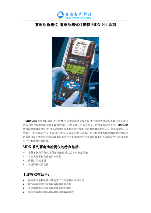
¾ 0C to +50C (32F to +122F)
测试范围:
¾ CCA: 100-2000 BY 5 ¾ CA: 100-2000 BY 5 ¾ MCA: 100-2000 BY 5 ¾ JIS#: By Part Number ¾ EN: 100-2000 BY 5 ¾ DIN: 100-1200 by 5 ¾ SAE: 100-2000 by 5 ¾ IEC: 100-1200 by 5
蓄电池测试仪的应用
1、蓄电池测试技术的发展 对于汽车蓄电池来说,冷起动电流是其最重要的指标,以冷起动电流的单位进行显示, 为的是让用户使用起来更加直观明了。电导仪在使用时,根据蓄电池的标注输入其额定 CCA 值,然后仪表会测出一个电导 CCA 值,仪表正是通过两个 CCA 值差异的比较,对蓄电池 的健康状况进行判定,所以世界上绝大多数国家对蓄电池的标注都是使用冷起动电流,近几 年国际业界基本都采取电导测试法。 国际电气和电子工程师协会(IEEE )标准 1118-1996 中的规定成为电导汽车蓄电池测 试仪的测试原理和判断依据。
专业分析检测设备。汽车蓄电池对于汽车来说,尽管在成本上所占的比重不高,但它对整部 汽车却起着举足轻重的作用。所以,了解汽车蓄电池是否仍然良好,提前更换将要报废的蓄 电池,能有效提高企业的服务水平和用户满意度,为蓄电池生产企业、汽车生产线、汽车维 修企业和蓄电池经销企业以及其他用户在蓄电池的检测工作中带来极大的便利。
2、传统办法健康的判定 判定蓄电池健康状况的传统办法就是放电方式,一般通过放电来测试蓄电池目前的实际 容量,从而判定蓄电池的健康状况。对于汽车蓄电池来说,国际蓄电池协会(BCI)规定, 在常温下以 1/2 的额定冷起动电流值进行放电 15 秒,如果蓄电池电压为 9.6V 以上,这个蓄 电池就通过了放电实验,是个健康的蓄电池。
Victron Energy智能充电控制器MPPT250系列说明说明书
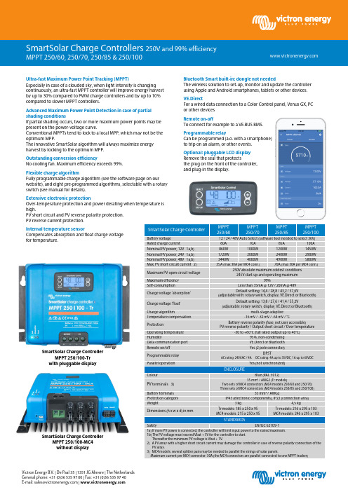
Victron Energy B.V. | De Paal 35 | 1351 JG Almere | The Netherlands General phone: +31 (0)36 535 97 00 | Fax: +31 (0)36 535 97 40 E-mail:***********************|SmartSolar Charge ControllerMPPT 250/60 MPPT 250/70 MPPT 250/85 MPPT 250/100Battery voltage12 / 24 / 48V Auto Select (software tool needed to select 36V)Rated charge current60A 70A 85A 100A Nominal PV power, 12V 1a,b) 860W 1000W 1200W 1450W Nominal PV power, 24V 1a,b) 1720W 2000W 2400W 2900W Nominal PV power, 48V 1a,b) 3440W 4000W 4900W 5800W Max. PV short circuit current 2) 35A (max 30A per MC4 conn.) 70A (max 30A per MC4 conn.)Maximum PV open circuit voltage 250V absolute maximum coldest conditions 245V start-up and operating maximumMaximum efficiency 99%Self-consumptionLess than 35mA @ 12V / 20mA @ 48V Charge voltage 'absorption' Default setting: 14,4 / 28,8 / 43,2 / 57,6V(adjustable with: rotary switch, display, VE.Direct or Bluetooth) Charge voltage 'float' Default setting: 13,8 / 27,6 / 41,4 / 55,2V(adjustable: rotary switch, display, VE.Direct or Bluetooth)Charge algorithmmulti-stage adaptive Temperature compensation -16 mV / -32 mV / -64 mV / °CProtectionBattery reverse polarity (fuse, not user accessible)PV reverse polarity / Output short circuit / Over temperatureOperating temperature -30 to +60°C (full rated output up to 40°C)Humidity95%, non-condensing Data communication port VE.Direct or Bluetooth Remote on/off Yes (2 pole connector)Programmable relay DPSTAC rating: 240VAC / 4A DC rating: 4A up to 35VDC, 1A up to 60VDCParallel operationYes (not synchronized)ENCLOSUREColourBlue (RAL 5012)PV terminals 3)35 mm² / AWG2 (Tr models)Two sets of MC4 connectors (MC4 models 250/60 and 250/70) Three sets of MC4 connectors (MC4 models 250/85 and 250/100)Battery terminals 35 mm² / AWG2Protection category IP43 (electronic components), IP22 (connection area)Weight3 kg 4,5 kgDimensions (h x w x d) in mmTr models: 185 x 250 x 95 MC4 models: 215 x 250 x 95 Tr models: 216 x 295 x 103 MC4 models: 246 x 295 x 103STANDARDSSafetyEN/IEC 62109-11a) If more PV power is connected, the controller will limit input power to the stated maximum.1b) The PV voltage must exceed Vbat + 5V for the controller to start. Thereafter the minimum PV voltage is Vbat + 1V.2) A PV array with a higher short circuit current may damage the controller in case of reverse polarity connection of the PV array.3) MC4 models: several splitter pairs may be needed to parallel the strings of solar panels.Maximum current per MC4 connector: 30A (the MC4 connectors are parallel connected to one MPPT tracker)Bluetooth Smart built-in: dongle not neededThe wireless solution to set-up, monitor and update the controller using Apple and Android smartphones, tablets or other devices.VE.DirectFor a wired data connection to a Color Control panel, Venus GX, PC or other devicesRemote on-offTo connect for example to a VE.BUS BMS.Programmable relayCan be programmed (a.o. with a smartphone) to trip on an alarm, or other events.Optional: pluggable LCD display Remove the seal that protectsthe plug on the front of the controller, and plug-in the display.Ultra-fast Maximum Power Point Tracking (MPPT)Especially in case of a clouded sky, when light intensity is changing continuously, an ultra-fast MPPT controller will improve energy harvest by up to 30% compared to PWM charge controllers and by up to 10% compared to slower MPPT controllers.Advanced Maximum Power Point Detection in case of partial shading conditionsIf partial shading occurs, two or more maximum power points may be present on the power-voltage curve.Conventional MPPTs tend to lock to a local MPP, which may not be the optimum MPP.The innovative SmartSolar algorithm will always maximize energy harvest by locking to the optimum MPP.Outstanding conversion efficiencyNo cooling fan. Maximum efficiency exceeds 99%.Flexible charge algorithmFully programmable charge algorithm (see the software page on our website), and eight pre-programmed algorithms, selectable with a rotary switch (see manual for details).Extensive electronic protectionOver-temperature protection and power derating when temperature is high.PV short circuit and PV reverse polarity protection. PV reverse current protection.Internal temperature sensorCompensates absorption and float charge voltage for temperature.SmartSolar Charge ControllerMPPT 250/100-MC4 without displaySmartSolar Charge ControllerMPPT 250/100-Tr with pluggable display。
智能保电器:三利特斯普SMX2200XLRT2U说明书
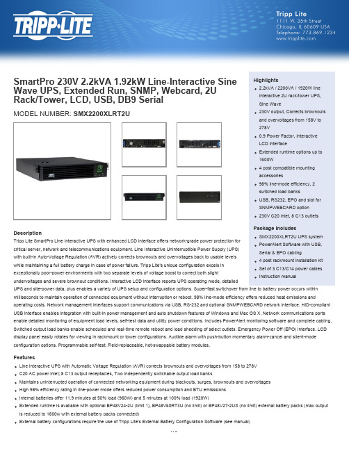
SmartPro 230V 2.2kVA 1.92kW Line-Interactive Sine Wave UPS, Extended Run, SNMP, Webcard, 2U Rack/Tower, LCD, USB, DB9 Serial Highlights2.2kVA / 2200VA / 1920W lineinteractive 2U rack/tower UPS, Sine WaveHot-swappable, user-replaceable internal batteries and external battery packs can be replaced with no disruption to connected equipmentFront panel LCD monitoring screen with MODE and ENTER buttons reports operating mode with 5-bar battery charge graphic, plus 7 selectable screens of detailed UPS and site power informationLCD interface also supports a number of advanced user setup and operating preferencesShips with 4 post rackmount installation hardware; Optional 2POSTRMKITWM enables 2 post rackmount/wallmount installation; Optional 2-9USTAND enables tower placementBuilt-in USB, RS-232 and optional SNMPWEBCARD accessory monitoring optionsHID-compliant USB interface enables integration with built-in power management and auto shutdown features of Windows and Mac OS XIncluded PowerAlert UPS monitoring software; Built-in Emergency Power Off (EPO) interface with cableOptional PDUBHV20 bypass PDU enables hot-swappable UPS replacement with no disruption to connected equipment SpecificationsOUTPUTOutput Volt Amp Capacity (VA)2200Output kVA Capacity (kVA) 2.2Output Watt Capacity (Watts)1920Output kW Capacity (kW) 1.92Nominal Output Voltage(s)220V; 230V; 240VSupportedNominal Voltage Details230V inverter output in battery modeFrequency Compatibility50 / 60 HzOutput Voltage Regulation (Line-15%, +6%Mode)Output Voltage Regulation (Battery+/- 5%Mode)Output Receptacles(8) C13Included Output Power Cables Includes 3 C13 to C14 output power cablesLoad Management Receptacles Two switchable single-outlet C13 load banksHot-Swap PDU options PDUBHV20 (2U / 6 C13, 2 C19 outlets)Output AC Waveform (AC Mode)Sine waveOutput AC Waveform (Battery Mode)Pure Sine waveINPUTRated input current (Maximum Load)10.7ANominal Input Voltage(s) Supported230V ACUPS Input Connection Type C20 inletUPS Input Connection Description IEC320-C20 input connection accepts a variety of detachable cordsets to match country or site-specific wallreceptaclesInput Circuit Breakers15AInput Phase Single-PhaseBATTERYFull Load Runtime (min.) 5 min. (1920w)Half Load Runtime (min.)11.9 min. (960w)Expandable Battery Runtime Extended runtime supported via optional external battery packsExternal Battery Pack Compatibility BP48V24-2U (limit 1); BP48V60RT-3U (multi-pack compatible); BP48V27-2US (multi-pack compatible)DC System Voltage (VDC)48Battery Recharge Rate (IncludedBatteries)Less than 4.5 hours from 10% to 90% (typical, full load discharge)Internal UPS Replacement BatteryCartridgeRBC94-2UBattery Access Front panel battery access doorBattery Replacement Description Hot-swappable, user replaceable batteriesVOLTAGE REGULATIONVoltage Regulation Description Automatic voltage regulation (AVR) maintains line power operation with an input voltage range of 158 to 278 Overvoltage Correction Voltage reduction of 12% applies when input is between 244-278VUndervoltage Correction Voltage boost of 12% applies when input voltage is between 183-206VSevere Undervoltage Correction Voltage boost of 24% applies when input voltage is between 158-182VLEDS ALARMS & SWITCHESFront Panel LCD Display Front panel LCD information and configuration screen offers detailed UPS and site power status and operating data, plus configuration of voltage, operating mode, alarm function and a variety of additional options (see manual for detailed LCD configuration and monitoring options)Audible Alarm Audible alarm indicates UPS startup, power-failure, low-battery, overload, UPS fault and remote shutdown conditionsAlarm Cancel Operation Power-fail alarm can be temporarily silenced using alarm-cancel switch; silent mode alarm configuration optionavailableSwitches 3 pushbutton switches control OFF / ON power status, MODE selection and MUTE / ENTER control functions SURGE / NOISE SUPPRESSIONUPS AC Suppression Joule Rating350UPS AC Suppression ResponseTimeInstantaneousEMI / RFI AC Noise Suppression YesPHYSICALIncluded Mounting AccessoryDescription4 post rackmount installation accessories includedInstallation Form Factors Supported2 post rackmount (2POSTRMKITWM); Wallmount (2POSTRMKITWM); Tower (2-9USTAND) with Optional AccessoriesPrimary Form Factor RackmountUPS Power Module Dimensions3.5 x 17.5 x 19.5(hwd, in.)UPS Power Module Dimensions8.9 x 44.4 x 49.5(hwd, cm)Rack Height (U Spaces)2UPS Power Module Weight (lbs.)68.75UPS Power Module Weight (kg)31.2UPS Shipping Dimensions (hwd / in.)9.25 x 24.75 x 22.5UPS Shipping Dimensions (hwd /23.5 x 62.9 x 57.2cm)Shipping Weight (lbs.)82.3Shipping Weight (kg)37.3Cooling Method FanUPS Housing Material SteelENVIRONMENTALOperating Temperature Range+32 to +104 degrees Fahrenheit / 0 to +40 degrees CelsiusStorage Temperature Range+5 to +122 degrees Fahrenheit / -15 to +50 degrees CelsiusRelative Humidity0 to 95%, non-condensingAC Mode BTU / Hr. (Full Load)161AC Mode Efficiency Rating (100%98%Load)COMMUNICATIONSCommunications Interface USB (HID enabled); DB9 Serial; EPO (emergency power off); Slot for SNMP/Web interfaceNetwork Monitoring Port Description Supports detailed monitoring of UPS and site power conditionsPowerAlert Software IncludedCommunications Cable USB, DB9 and EPO cabling includedWatchDog Compatibility Supports Watchdog application, OS and hard-reboot restart options for remote applications LINE / BATTERY TRANSFERTransfer Time 6 ms. (AC to DC) / 1 ms. (DC to AC)Low Voltage Transfer to Battery158VPower (Setpoint)High Voltage Transfer to Battery278VPower (Setpoint)SPECIAL FEATURESGrounding Lug Back panel grounding lugCold Start (Startup in Battery ModeCold-start operation supportedDuring a Power Failure)High Availability UPS Features Hot swappable batteriesGreen Energy-Saving Features Greater than 95% efficiency - GREEN UPS; Individually controllable load banksCERTIFICATIONSUPS Certifications CEUPS Certification Details IEC 62040-1, IEC 62040-2 Class A EMI, GOSTWARRANTYProduct Warranty Period2-year limited warranty(International)Product Warranty Period (Mexico)2-year limited warrantyProduct Warranty Period (Puerto2-year limited warrantyRico)© 2015 Tripp Lite. All rights reserved. All trademarks are the sole property of their respective owners. Tripp Lite has a policy of continuous improvement. Specifications are subject to change without notice. Photos may differ slightly from final products.。
ProMix
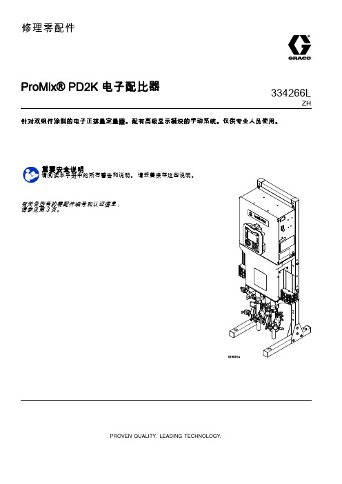
修理零配件ProMix®PD2K电子配比器334266LZH 针对双组件涂料的电子正排量定量器。
配有高级显示模块的手动系统。
仅供专业人员使用。
重要安全说明请阅读本手册中的所有警告和说明。
请妥善保存这些说明。
有关各型号的零配件编号和认证信息,请参见第3页。
PROVEN QUALITY.LEADING TECHNOLOGY.Contents型号 (3)相关手册 (6)警告 (7)异氰酸酯(ISO)的重要信息 (10)重要的酸性催化剂信息 (12)酸性催化剂情况 (12)酸性催化剂的湿气敏感性 (12)故障排除 (13)系统故障排除 (13)故障代码排除 (14)喷涂间控制台故障排除 (25)电源栅栏板故障排除 (26)隔离板故障排除 (27)增强型流体控制模块故障排除 (28)泵模块故障排除 (29)高级显示模块故障排除 (30)电气示意图 (31)标准型号(MC1000、MC2000、MC3000、MC4000) (31)双面板型号(MC1002、MC2002、MC3002、MC4002) (38)可选的电缆和模块 (44)通信选项(用于PLC和AWI)...................45修理. (46)维修之前的工作 (46)泄压步骤 (47)修理高级显示模块(ADM) (48)维修控制箱 (49)维修流体通路段 (58)零部件 (63)定量器零件(标准型号) (63)定量器零件(双面板型号) (66)控制盒零件(标准型号) (69)控制盒零件(双面板型号) (72)电磁阀歧管部件 (75)修理配件包和附件 (76)软管束 (76)腰带歧管涂料混合套件 (77)本质安全的远程变色套件 (77)换色和更换催化剂套件 (78)式喷枪 (78)泵扩展套件 (79)通信套件 (79)升级套件 (79)注释 (80)技术数据 (81)型号型号参见图1-7获取组件识别标牌,包括核准信息和认证。
飞宇 CX605 CX610 微型无人机电池六通道充电器说明书

用户使用说明书CX610 / CX605微型无人机电池六通道充电器产品特点●操作简单,即插即用。
●内部芯片智能温度检测,保障充电安全。
●六通道独立充电输出,可同时充电六个电池。
●直流3.5mm插孔/电池专用XT60接口/Micro usb 三种输入方式。
●充电电流连续可调,设置范围0.1A~1A@CX610 / 0.1A~0.5A@CX605。
● LED数码管显示输入电压、六通道电池电压、输入低电压保护值、设定电流值。
●**********/2.0A/1.0A智能快速充电接口,支持苹果,安卓手机快充协议。
输入电源连接1. 使用接口为XT60的3~6串锂电池组供电。
(低压过放保护值自动设置,用户可手动调整)2. 使用外径为3.5mm的DC接口供电,电压范围:9~26V。
(可接AC适配器或车载点烟器12V)3. 使用手机充电器的Micro USB接口供电,电压范围:5V±5%。
(电流0.5~2.4A)USB输出连接1. 连接手机、平板电脑等需要充电的设备至OUT USB端口,输出电压范围:5V±5%。
(充电智能协议识别功能,自动调整充电电流0.5~2.4A)充电电池连接1. MCX接口连接针间距1.25mm。
2. mCPX接口连接针间距2.0mm。
3. MOLEX接口连接针间距2.0mm。
(需使用配套的转接线mCPX to MOLEX)4. JST接口连接针间距2.54mm。
(需使用配套的转接线mCPX to JST)用户参数设置1. 电源输入模式设置长按电压设置按钮,数码管会闪烁显示BAT或DC,短按电压设置按钮,可以在BAT和DC两个模式之间切换;短按电流设置按钮确认保存当前闪烁的电源模式。
BAT表示:BATTERY电池模式,即XT60接口连接的电池,该电源模式下,充电器会智能识别电池的节数,智能设置低压保护值,防止XT60接口的电池过放电。
该模式下也可以手动调整低压保护值。
CTEK MULTI 7000电池充电器使用说明书 (自动保存的)
CTEK MULTI 7000吊厢电池充电器使用说明书一、简要说明感谢你购买MULTI XS 7000开关式电源充电器,本充电器具备:脉冲修复、浮充、电量分析和修复等功能,由瑞典AB公司生产,是众多CTEK专业充电器系列产品中的一款。
同时本产品拥有了当前电池充电器行业的先进技术,可延长电池使用寿命。
在使用前,请认真阅读该手册,并认真遵守相关使用说明。
二、安全提示●该产品主要用于为容量为14—225AH的铅酸蓄电池充电,请勿作它用;●在将充电器与电池作连接或者断开的时候,请带上具有保护作用的护目镜,同时将头扭开;●电池液体具有腐蚀性。
如果不慎,电池液碰到皮肤或者进入眼睛,请立即使用大量清水冲洗,并及时就医;●确保勿将电源线折叠或者放在高温处,或者锋利的地方,防止绝缘损坏;●在充电的时候,电池会产生可燃气体,所以务必确保近距离内没有火源存在;●在充电过程中,确保通风良好;●勿在充电器上放置任何覆盖物;●确保电源线勿碰到水;●决不能对不可充电池进行充电;●决不能对已经损坏的电池进行充电;●在充电过程中,请勿将充电器置于电池之上;●导线连接处理必须满足正常的大电流充电需求;●充电之前须先检查电源线。
确保电源线没有破损,破损的电源线不能使用;●充电的时候若无人照看或者长时间充电的情况下,须检查充电器已经转换到维护充电模式。
若3天内,充电器都未能成功切换到修复充电模式,这就意味着有故障存在。
这种情况下,必须人为断开电路连接。
●所有电池均会失效,不过只是时间长短而已。
在充电过程中,若出现电池失效的情况,通常情况下本设备会根据自身先进的控制功能安全处理。
但可以肯定的是电池可能会出现其它不可预测的状况。
在该情况下,若长时间充电,请时刻留意本电池充电器的工作状态;●本产品仅能安装在地势平坦的地方;●本产品禁止小孩使用,仅限能按照本操作手册安全操作的人员使用。
不管是存放还是使用本产品,请都远离小孩。
三、适用电池类型及相关设置本产品能对多种12V铅酸蓄电池进行充电。
蓝格尔MICRO-200 Pro蓄电池检测仪使用说明书
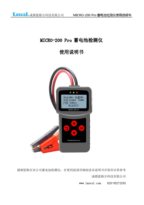
MICRO-200Pro蓄电池检测仪使用说明书感谢您购买本公司蓄电池检测仪,在使用前请详细阅读本说明书并保存以供参考成都蓝格尔科技有限公司蓝格尔MICRO-200Pro蓄电池检测仪,采用目前世界上最先进的电导测试技术,可以方便、快速、准确的测量汽车电池、摩托车电池的实际冷起动电流能力,电池本身的健康程度,以及快速检测起动系统和充电系统的常见故障,有利于维修人员快速准确判断汽车、摩托车的故障位置,便于快速维修。
产品说明:1、质保期一年,终身维修2、应用:12V汽车电池、12V摩托车电池;12V&24V起动系统和充电系统3、工作范围:测量标准测量范围CCA40-2000BCI40-2000CA40-2000MCA40-2000JIS26A17—245H52DIN40-1400IEC40-1400EN40-2000SAE40-2000GB3-220Ah4、工作温度:-20℃到50℃5、特殊测试夹:双导体开尔文夹6、外壳材料:耐酸ABS塑料7、测量电池范围:3AH-220AH8、测量电压范围:7V—30V操作步骤1、将测试仪红黑夹子夹到被测电池上,红正黑负,测试仪显示屏会显示开机界面。
被测电池电压低于7.0V以下则无法正常测试;按OK键往下继续。
2、按照测试仪提示,按上下键可以依次选择:①电池测试②起动系统测试③充电系统测试④查看测试结果⑤打印测试结果⑥语言选择(1)电池测试选到第一项电池测试后,按OK键后依次提示:●电池类型选择:测试仪将提示选择电池类型,即选择普通电池,AGM平板电池,AGM卷绕电池,EFB电池,胶体电池。
按上下箭头键选择电池的类型,按OK键确认。
●输入标准选择:指电池的出厂标注标准,在电池的正上方或正前方可以看见,选择电池上标注的标准即可,如CCA、BCI、DIN等。
如没有找到任何标准,可以选择GB标准,直接输入Ah值测试。
选择GB标准会有少量误差。
●额定容量选择:指电池的出厂起动电流标准,在电池的正上方或正前方可以看见,如CCA500A。
CTEK 蓄电池充电器 MXS 7.0 使用说明书
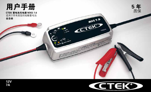
用户手册CTEK 蓄电池充电器 MXS 7.0适用于所有类型的铅酸蓄电池全自动5 年 质保12V 7A34可供使用该表显示完全放电的蓄电池充到 80% 容量的预计所需时间。
充电模式按下 MODE (模式)按钮,即可完成设置。
大约两秒钟后,充电器激活所选的模式。
下次连接充电器时,会重新启动所选模式。
出错指示灯当出错指示灯亮起时,请检查以下项目:1. 充电器的正极是否连接至蓄电池的正极?2. 充电器是否连接至 12V 蓄电池?3. 电池夹是否短路?4. 充电是在还是状态中断的?按下 MODE (模式)按钮,即可重新起动充电器。
如果充电仍被中断,则蓄电池... ...被严重硫化,可能需要更换。
...充不进电,可能需要更换。
...无法存电,可能需要更换。
警告!电池充电器上的防火花功能在 SUPPLY (供电)模式中被禁用。
步骤 1 去硫化探测已被硫化的蓄电池。
用脉冲电流和电压,消除蓄电池铅板上的硫酸盐,恢复电池容量。
步骤 2 软启动测试蓄电池能否被充电。
该步骤可避免向有故障的蓄电池充电。
步骤 3 快速充电用最大电流充至电池容量的 80% 左右。
步骤 4 平充电流逐渐递减,充到蓄电池的 100% 容量。
步骤 5 分析测试蓄电池是否能够保存电量。
无法存电的蓄电池可能需要更换。
步骤 6 活化选择 Recond(活化)模式,在充电过程中加入活化步骤。
在活化步骤中,充电电压提高,会在蓄电池中出现可控的析气现象。
析气可混合蓄电池内的硫酸,恢复电池容量。
步骤 7 浮充在恒压下充电,使蓄电池电压保持在最大值。
步骤 8 脉冲对蓄电池进行补偿充电,使其容量达到 95-100%。
充电器监测蓄电池电压,并在必要时发出一个充电脉冲,以保证蓄电池完全充满。
充电模式5充电器型号MXS 7.0型号编码1053额定交流电压220-240VAC, 50-60Hz充电电压NORMAL 14.4V,AGM 充电 14.7V,RECOND 15.8V,SUPPLY 13.6V起动电压 2.0V充电电流最大 7.2A交流输入电流 1.2A rms(在最大充电电流下)反向漏电流*<1Ah/月纹波**<4%环境温度-20°C 至 +50°C,高温下输出功率自动调低充电器类型 8 步骤全自动充电周期电池类型全部类型的 12V 铅酸蓄电池(WET, MF, Ca/Ca, AGM, GEL)电池容量14-150Ah,可至 225Ah作补偿充电尺寸191 x 89 x 48mm(长 x 宽 x 高)防护等级IP65重量0.8kg*)反向漏电流指充电器未接上交流电源时,充电器泄漏蓄电池的电流。
CTEK PRO 120 使用手册说明书

如何操作 1 请阅读安全说明
2
1
2
@FAQ
3
4
PRO120
3秒
PRO120
MAIN MENU(主菜单) CHARGE(充电) POWER SUPPLY(供电) SETTINGS(设置)
SELECT(选择)
充电模式充锂电池(LiFePO4),反之 亦然。
充电模式
PRO120
PRO120
PRO120
PRO120 用于给电池充电或保养
MAIN MENU(主菜单) CHARGE (充电模式) POWER SUPPLY(电源模式) SETTINGS(设置)
SELECT(选择)
按此键可在菜单中向上滚动以增加数值。 按此键可在菜单中向下滚动以减少数值。 按此键以激活已选模式或者设置。 按此键在菜单中后退或停止。
CN • 5
7/17/2019 1:09:01 PM
设置
PRO120 PRO120
MAIN MENU(主菜单) CHARGE(充电模式) POWER SUPPLY(电源模式) SETTINGS(设置)
SELECT(选择)
PRO120
PRO120
按此键可在菜单中向上滚动以增加数值。 按此键可在菜单中向下滚动以减少数值。 按此键以激活已选模式或者设置。 按此键在菜单中返回或停止。
··电源插头接地的充电器只能连接接地的 电源插座。
··充电时,铅酸电池会排放爆炸性气体。防 止火花接近电池。提供良好的通风。
··IP等级低于IPX4的充电器专用于室内。请 参见技术规格。请勿将充电器置于雨中或 雪中。
··将充电器连接到电池的正极,然后连接到 负极。对于安装在车内的电池,将负极接 头连接到车辆底盘,远离燃油管。然后, 连接充电器与电源。
SEMTECH公司简介

2.2.1 电池充电器
器件
描述
SC1410A 恒定电压 /恒定电流电池充电器
SC801 全集成大电流锂电池充电系统
器件
SC802 SC803
描述ቤተ መጻሕፍቲ ባይዱ
带计时器的全集成锂电池充电系统 全集成大电流锂电池充电系统
2.2.2 分布式电源调整器 DC/DC,非隔离型
器件
描述
Single-Output Switching Regulators
目录
1 SEMTECH 公司简介 ...............................................................................................................2 2 电源管理产品...........................................................................................................................2
SEMTECH 产品
1 SEMTECH 公司简介
Semtech International 公司设计、制造、销售广泛的模拟和混合信号的半导体产品。它专 注的提供给客户全部的解决方法和突破性技术,主要产品包括电源管理、保护器件、先进的 通信器件、人机接口、高速测试和定时产品。公司的集成电路、分离器件产品主要用于通信、 计算机、计算机外设、视频、自动测试设备和其他的商业及军事上的应用。
2 电源管理产品
2.1 电源管理器件概述
Semtech 的电源管理器件是世界上领先的台式电脑、电信系统、笔记本电脑及手持设备 解决方案。Semtech International 是台式电脑电源处理产品的领导者,如工业上第一个组合调 整器以用于 Pentium 系统所需的三种电源,第一个多相位控制器。电流产品包括一套用于 Intel 和 AMD 处理器提供的电源管理产品。快速的面向和适应市场的做法使我们成为计算 机工业的优良的供应商。我们提供全线的开关调整器,线性调整器,FET 控制器,MOSFET 驱动器和基准用于台式电脑。Semtech International 的手持设备产品设计的目标是增加电池寿 命并减少 PCB 面积。Semtech International 完整的电源管理方案适应不断变化的市场,比如: 蜂窝电话,PDA,GPS,寻呼机,无线电话,网络电话及小灵通.拥有全线的从 CMOS LDO 到小如充电泵之类的开关产品。如电源管理,电池管理,用户输入接口,外设接口和静电防 护器件,单端或双端输出开关调整器,线性调整器,MOSFET 驱动器和精密参考。
1.5KW-8KW锂电车载充电机
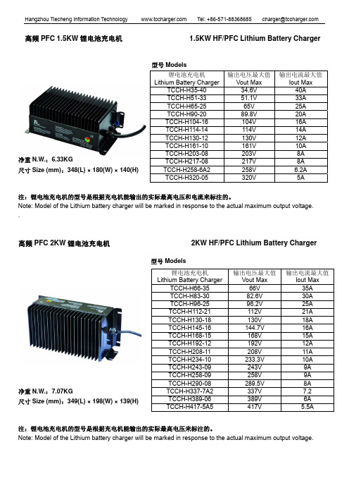
型号Models净重N.W.:6.33KG尺寸Size (mm):348(L) × 180(W) × 140(H)注:锂电池充电机的型号是根据充电机能输出的实际最高电压和电流来标注的。
Note: Model of the Lithium battery charger will be marked in response to the actual maximum output voltage. .高频PFC 2KW 锂电池充电机 2KW HF/PFC Lithium Battery Charger型号Models净重N.W.:7.07KG尺寸Size (mm):349(L) × 198(W) × 139(H)注:锂电池充电机的型号是根据充电机能输出的实际最高电压来标注的。
Note: Model of the Lithium battery charger will be marked in response to the actual maximum output voltage.锂电池充电机 Lithium Battery Charger 输出电压最大值 Vout Max 输出电流最大值Iout MaxTCCH-H35-40 34.6V 40A TCCH-H51-33 51.1V 33A TCCH-H65-25 65V 25A TCCH-H90-20 89.8V 20A TCCH-H104-16 104V 16A TCCH-H114-14 114V14A TCCH-H130-12 130V 12A TCCH-H161-10 161V 10ATCCH-H203-08 203V 8A TCCH-H217-08 217V 8A TCCH-H258-6A2 258V 6.2A TCCH-H320-05 320V 5A锂电池充电机 Lithium Battery Charger 输出电压最大值 Vout Max 输出电流最大值Iout MaxTCCH-H66-35 66V 35A TCCH-H83-30 82.6V 30A TCCH-H96-25 96.2V 25A TCCH-H112-21 112V 21A TCCH-H130-18 130V 18A TCCH-H145-16 144.7V 16A TCCH-H168-15 168V 15A TCCH-H192-12 192V 12A TCCH-H208-11 208V 11A TCCH-H234-10 233.3V 10A TCCH-H243-09 243V 9A TCCH-H258-09 258V 9A TCCH-H290-08 289.5V 8A TCCH-H337-7A2 337V 7.2 TCCH-H389-06 389V 6A TCCH-H417-5A5 417V 5.5A型号Models净重N.W.:10.24KG尺寸size (mm):257(L) × 254(W) × 179(H)注:锂电池充电机的型号是根据充电机能输出的实际最高电压来标注的。
Xantrex技术有限公司新世代自由SW系列电源充电器说明说明书

Over-temperature shutdown
541 Roske Drive, Suite A
Automatic overload protection
Elkhart, Indiana
Short-circuit protection USA 46516
Integrated, resettable AC breakers
2000
Watts
3000
Watts
Certified to CSA Standard C22.2 No. 107.1 UL 458 with marine supplement FCC Class B
Parallel and Series Stacking - NEW FEATURE Parallel stacking enables the Freedom SW inverter/chargers to double the AC output in inverter mode Series stacking enables the Freedom SW inverter/chargers to generate 120/240 V split phase output²
Regulatory & Environmental Compliance
Flooded / gel / AGM 1 leg of 30 A < 20 ms - 4°F to 140°F (- 20°C to 60°C) - 40°F to 185°F (- 40°C to 85°C) 7.75 x 13.5 x 15.25” (19.7 x 34.3 x 38.7 cm) 27.5 kg (60.5 lbs) 2 years 1 11.8 x 17.1 x 20.5” (30 x 43.5 x 52.2 cm) 30 kg (66 lbs) 815-2012
CH9721P+ CH9722P CH9723P+ CH9733P+ 快充自动测试仪 使用说明书

使用说明书OPERATION MANUALCH9721P+/CH9722P/CH9723P+/CH9733P+快充自动测试仪常州市贝奇电子科技有限公司BEICH ELECTRONIC TECHNOLOGY CO.,LTD.公司声明注意事项:本说明书版权归常州市贝奇电子科技有限公司所有,贝奇电子保留所有权利。
未经贝奇电子书面同意,不得对本说明书的任何部分进行影印、复制或转译。
本说明书适用于CH9721P+快充PD 自动测试仪本说明书适用于CH9722P 快充PD 自动测试仪本说明书适用于CH9723P+快充PD 自动测试仪本说明书适用于CH9723P+快充PD 自动测试仪本说明书包含的信息可能随时修改,恕不另行通知。
最新的说明书电子文档可以从贝奇电子官方网站下载:2017年8月……………………………………..第一版2017年11月…………………………………..第二版2018年10月…………………………………..第三版2019年5月……………………………………..第四版2020年10月……………………………………第五版2021年1月……………………………………..第六版2021年10月…………………………………..第七版本说明书所描述的可能并非仪器所有内容,贝奇电子有权对本产品的性能、功能、内部结构、外观、附件、包装物等进行改进和提高而不作另行说明!由此引起的说明书与仪器不一致的困惑,可与我公司联系。
安全警告:在使用操作和维护本仪器的任何过程中,务必遵守各项安全防护措施。
如果忽视和不遵守这些安全措施及本手册中的警告,不但会影响仪器性能,更可能导致仪器的直接损坏,并可能危及人身安全。
对于不遵守这些安全防范措施而造成的后果,贝奇电子科技有限公司不承担任何后果。
触电危险操作,测试与与仪器维护时谨防触电,非专业人员请勿擅自打开机箱,专业人员如需更换保险丝或进行其它维护,务必先拔去电源插头,并在有人员陪同情况下进行。
光伏充电控制器MP-3722用户手册说明书

PV Charge ControllerMP-3722User's ManualTable of ContentsPrecautions and Specifications 11.Introduction 22.Control and Indicator 23.Installation and Indication 3 3.1 Connection 3 3.2 LED Indicator 3 3.3 LCD Display 43.3.1 LCD Display Sequence 4 3.4 The Dip Switch, Set-Buttons and Reset Button Functions 43.4.1 Adjust the PV Charge Controller Settings 43.4.2 Select the Auto/Manual Equalization charging and Night-Light Mode 64.PV Charge Control Mode 6 4.1 3-Stage Charge Control 6 4.2 Equalization Charging Mode (Automatic or Manual) 64.2.1 Automatic Equalization Charging 64.2.2 Manual Equalization Charging 6 4.3 12V DC Load Terminal- Control Mode 74.3.1 Low Voltage Disconnect (LVD) 74.3.2 Low Voltage Reconnect (LVR) 74.3.3 Night-Light Mode Programs 8 4.4 Temperature Sensor (Optional) 84.5 Over Temperature Protection 95.Remote Signal Terminal (Optional) 10Precautions1.Before using the charge/load controller, read all the instructions and cautionary markings on thecharge/load controller, the batteries and the photovoltaic panels.2.Do not attempt to repair the controller. Incorrect re-assembly may result in a risk of electric shock orfire.3.To reduce risk of electric shock, disconnect all wiring before attempting any maintenance or cleaning.Turning off controls will not reduce this risk. PV panels produce power when exposed to light – cover them with opaque material before servicing.4.Working in Vicinity of a Lead Acid Battery is dangerous. Batteries generate EXPLOSIVE gases duringnormal operation. Provide ventilation to outdoors from the highest point of the battery compartment.5.This charge/load controller is intended to be used with a battery supply of 12 VDC nominal voltage.6.Be extra cautious to reduce the possibility of dropping a metal tool onto batteries. It might spark orshort-circuit batteries or other electrical parts that may cause explosion. Cover wrench handles with plastic tape or vinyl dip coating material.SpecificationsModels MP-3722Battery voltage12VMaximum PV panel open circuit voltage26VContinuous load/charge current 30AMaximum charge current (5 mins)35AMaximum load current (5 mins)35AOperation current(no Load and no PV)15mAVoltage across terminals (PV to Battery) 1.2VVoltage across terminals (Battery to Load)0.6VElectronic Blocking(To protect against reverse polarity connection of PV panel and to blockYescurrent from battery to PV panel when voltage of battery is higher than PVpanel)Battery reverse polarity protection YesOvercharge & Over-discharge protection YesBattery status LED indication5-State LED IndicationsCharging status indication3-State LCD Display Recommended wire size#10AWGWeight0.48kgDimension (WxDxH)150 x 85 x 45 mmFuse40AOperating ambient temperature-10 to 50 °COver temperature protection YesBattery charging float voltage setting Adjustable from 12.0-16.5VBattery charging bulk voltage setting Adjustable from 12.0-16.5VDC load control mode (For DC load terminal):Low Voltage Disconnect(LVD)Adjustable from 8-16VLow Voltage Reconnect(LVR)Adjustable from 8-16V1. IntroductionThe MP-3722 PV Charge Controller is designed for use with all types of 12V photovoltaic(PV) panels/systems and different types of 12V batteries, such as wet or sealed lead acid, lead calcium, lead antimony battery.Numerous features are provided to maximize the performance of the system:●Electronic Blocking ( To protect against reverse polarity connection of PV panel and blockcurrent from battery to PV Panel when voltage of Battery is higher than PV panel),●Suitable for PV panels with Open Circuit Voltage from 17 to 23V,●Rated charging/load current 30A(MP-3722),●PWM Charging with 3-stage Charge Control (to allow battery be left unattended for longperiod),●User Adjustable Charge Control Settings for different types of batteries,●User Adjustable Low Voltage Disconnect and Low Voltage Reconnect,●Build-In Microprocessor for PV charge control to maximize the charging efficiency,●Overcharge and Over-discharge Protection,●Over Temperature Protection,●Short-Circuit Protection at load terminal (5) & Battery Reverse Polarity Protection at BatteryConnection Terminal (6),●Informative LCD Display and Tri-Color LED indication of system and battery conditions,●Optional Temperature Sensor for compensated battery charging,●Optional Remote Signal Terminal.2. Control and IndicatorThe following diagram shows the hardware interface of the PV Charge Controller.Figure 1 Front view of PV Charge Controller1.Battery LED Indicator2.LCD Display3.Reset button (see Section 3.4)4.Temperature Sensor (Optional )5.12V DC Load terminal with Low Voltage Disconnect/NIGHT-LIGHT mode (Section 4.3)6.12V Battery connection terminal7.PV Panel connection terminal8.Remote Signal Terminal (Optional )9.Side Door (open to access switches for setting)3. Installation and Indication3.1 ConnectionThe PV Charge Controller should be connected as follow:Figure 2 Connection of PV Charge ControllerThis controller has Electronic Blocking feature, therefore, it is not necessary to connect a diode between the PV module and the Controller.The recommended wire size is #10AWG(MP-3722).It is recommended that the PV Charge Controller should be installed in a dry, sheltered location away from sources of high temperature and moisture.3.2 LED IndicatorRed Flashing....................Battery Voltage is lower than 12.6VConstant Red...................Battery Voltage has reached Low Voltage Disconnect(LVD)Constant Green................Battery Voltage is higher than 12.6VGreen Flashing................Battery Voltage has reached Bulk Charging Setting.(Fully Charged)Orange Flashing...............Battery Voltage is lower than Low Voltage Disconnect (LVD)Voltage Setting and load has been disconnected.Red-Green Flashing.........Equalization Charging in process.Table 1 LED Indications3.3 LCD DisplayThe LCD Display shows the battery voltage, PV panel voltage and the charging modes during normal day time operation. At night time or low sunlight or PV disconnected situation, display of PV VOLT value is to be ignored .LCD DISPLAY DescriptionsBATT VOLT.................Shows the Battery VoltagePV VOLT.......................Shows the PV panel Input Voltage to the systemPV CURR......................Shows the PV panel Input Current to the systemTOD PV_AH.................Shows the total Ampere-Hour input to the system in current day L1D PV_AH..................Shows the total Ampere-Hour input to the system a day before L2D PV_AH..................Shows the total Ampere-Hour input to the system 2 days before Charging StatusBULK CHARGE...........Shows the charging process is in Bulk chargeABSORB CHARGE......Shows the charging process is in Absorption chargeFLOAT CHARGE.........Shows the charging process is in Float chargeEQULIZ CHARGE........Shows the charging process is in Equalization chargePV < BATT VOLT........Indicates the PV voltage is less than the Battery VoltageTable 2 LCD Display3.3.1 LCD Display SequenceFigure 3The LCD Display Sequence.3.4 The Dip Switch , Set-Button and Reset button functionsThe dip switch, set buttons and reset button are used for adjusting the PV Charge Controller Settings (see Section 3.4.1 and 3.4.2)( * Open the Side door, you can see the dip switch & set buttons.)3.4.1 Adjust the PV Charge Controller SettingsFactory PresetThe following table shows the factory preset values of the PV Charge Controller :Bulk Voltage..................................................14.3V Float Voltage..................................................13.5V Low Voltage Disconnect................................11.5V Low Voltage Reconnect.................................12.5VNight Light Mode Option...............................Off (refer to Table 5 in Section 4.3.3)Table 3 Preset values of the adjustable parametersThe preset Bulk and Float Setpoints are for typical Sealed Gel-type Lead Acid Battery only.For typical wet-type Lead Acid Battery, set Bulk setpoint to 14.8V and Float setpoint to 13.5V.Please refer to battery manufacturer’s specific recommended values.How to adjust the Bulk, Float Charge Voltage, LVD, LVR and Night Light Mode 1.First take out all the connections to the PV controller except those to battery.2.Push up the slide cover at the right side of the PV controller.3.Push up all three DIP Switches to OFF position.4.Disconnect the battery negative terminal at the controller.5.Press and hold the Reset Button and reconnect the battery negative terminal again.6.After 3 to 5 seconds release the Reset Button and note the LCD shows “Float V “7.The controller is now in Set Mode , short presses of the Reset Button show as in following cyclic order with preset values :“FLOAT CH: , LVD , LVR , L OPTION:, Bulk CH , FLOAT CH ”8.Press the Set Button 1 and 2 to adjust the desired setting.9.When the desired settings are done , double check all settings by pressing the Preset Button.10.To store the new settings , push down the Dip Switch 2 to on position and take note of the LCD displays ”INITIALIZATION…. “until one complete cycle. Figure 5Figure 4Figure 6 Adjustable parameters in Setting Mode3.4.2 Select the auto- equalization charging and night-light modeThe dip switch 1 is for Night-Light Mode , switch 2 for Equalization Charging mode and switch 3 is always set at off positionTHE PV CHARGE CONTROLLER IS FACTORY PRESET FOR USE WITH SEAL TYPE BATTERYTHAT IS : NO AUTO EQUILIZATION CHARGING BECAUSE DIP SWITCH 2 IS AT ON POSITION.* Equalization(Eq.) charging is only for wet-type Lead Acid BatteryWhen Auto-Equalization Charging is set at ON mode , Equalization charge will occur for 2 hours once every thirty days.Use the dip switch to select equalization charging and night-light mode as below:AUTOEqualizationCharging*Night-Light ModeDip Switch SettingsOFFOFFDip switch 1 – OFFDip switch 2 – ON Dip switch 3 - OFFOFF ONDip switch 1 – ON Dip switch 2 – ON Dip switch 3 - OFF ON OFFDip switch 1 – OFF Dip switch 2 – OFF Dip switch 3 - OFF ONONDip switch 1 – ON Dip switch 2 – OFF Dip switch 3 - OFFTable 4 Dip Switch FunctionsFactoryPreset4. PV Charge Control ModeThe MP-3722 PV Charge Controller can operate in the several modes. This includes the 3-stage Charge Control, Equalization Charging Mode, DC Load Control Mode, NIGHT-LIGHT mode, Temperature Sensing and Over Temperature Protection features.4.1 3-Stage Charge ControlThe main function of charge controller is to regulate the flow of electricity from the photovoltaic panels to the batteries. In PV systems with batteries, the batteries must be protected from overcharging and be maintained at fully charged state.The PV Charge Controller uses the Micro-Processor and PWM ( Pulse Width Modulation ) to give optimal and safe charging .It makes varying On-Off pulses of electrical energy from the photovoltaic(PV) panel in charging the battery according to the battery state. It has 3 stages of charging, as follows:a. BULK CHARGE – At this mode, a preset maximum constant amount of current (amps) isfed into the battery as the no PWM is present. As the battery is being charged up , the voltage of the battery increases gradually.b. ABSORPTION CHARGE – After the preset voltage is reached (approximately 14.3 voltsfor a 12 volt system) the voltage is then held constant. As the battery continues to be charged at constant voltage, the charging current decreases. The charging voltage is held at the Bulk Voltage Setting for one full hour with various rapid On-Off pulses (PWM). It then switches to Float Charge Mode.c. FLOAT CHARGE –The controller will maintain the battery voltage at the float voltagesetting by giving shorter On-pulse charge to make up for any detected self discharge of the battery. When the battery voltage drops below the Float Voltage Setting for a total period of 10 minutes, a new charging cycle is activated in Bulk or Absorption Charge.The three stages charging method works well with the chemical reaction that occurs as a battery is being charged. When a battery is more discharged, a regulated maximum current can be applied, since there is a lot of material available for the reactions to occur.As the battery refills, less and less chemical material is available for the reaction. By using PWM to slowly reducing the charge current, while maintaining a preset high voltage, the battery is more closely refilled at the reaction rate of the chemicals. Finally, the Float voltage keeps the battery fully charged at all times taking care of the self discharge .Remarks:1.When the Battery is charged up to Bulk Charge Voltage setting, the LCD will only show theBulk charge voltage one or two times quickly, then the PV controller switches to Absorption charge2.The “Batt Volt” display during Absorption charge is less than Bulk Voltage Setting. Thedifference will decrease as the Absorption time increase.3.The “Batt Volt” display during Float Charge is less than the Float Charge Voltage Setting.4.2 Equalization Charging Mode (Automatic or Manual)WARNING: Equalization Charging is only for Wet-type Lead Acid Battery.The Equalization Charging Voltage is factory pre-set to the Bulk Voltage + 1 Volt.The battery manufacturer should be consulted. Clean, distilled water will need to be added to the battery AFTER the equalization process.4.2.1 Automatic Equalization ChargingAutomatic Equalization charge is only available when battery voltage is higher than the Low Voltage Disconnect (LVD) voltage , see 4.3.1.To set Automatic Equalization Charging, set the dip switch 2 to OFF position.The PV Charge Controller will perform Equalization charging for 2 hours once every 30 days During equalization charge , it can be stopped any time by pressing the Reset button once and the controller will return to the charging mode before the Equalization charge.4.2.2 Manual Equalization ChargingSet the Night-Light Mode , dip switch 1 to off position.P ress and hold the Reset button for 10seconds and the equalization charge will go on for two hour.During equalization charge , it can be stopped any time by pressing the Reset button once and the controller will return to the charging mode before the Equalization charge.4.3 12V DC Load Terminal – Control ModeThe 12V DC load terminal is designed for low power DC load such as street light.It prevents over-discharging the battery and has 10 Night-Light timer programs.4.3.1 Low Voltage Disconnect (LVD)When the battery voltage is lower than the Low Voltage Disconnect (LVD) setting for5 minutes, the LED will blink orange once every 2 seconds and the load will be cut off. After the load is cut off, user can press the Reset button once to switch on the load for a grace period of10 minutes for emergency purpose.4.3.2 Low Voltage Reconnect (LVR)When the battery voltage is higher than Low Voltage Reconnect (LVR) setting for 5 minutes, the controller will automatically reconnect the load.4.3.3 NIGHT-LIGHT Mode ProgramsIn the night-light mode, we have 10 selections.To Activate the NIGHT-LIGHT Mode, switch the dipswitch 1 to ON position.After activating, when the PV panel voltage is lower than 3.5V for 10 minute, the Controller will turn on the light for a preset period of time according to the option selected.When the PV panel voltage is higher than 3.5V for 10minute, the Controller will turn off the light.In NIGHT-LIGHT Mode, press and hold the Reset button can switch on the Light to test the light.Also, when the battery is lower than the Low Voltage Disconnect (LVD) for 5 minutes, the load will be cut off.When the battery voltage becomes higher than Low Voltage Reconnect (LVR) setting for 5 minutes, the controller will automatically reconnect the load again.The following chart shows the night light mode selections.LCD Display Explanation SUNSET NIGHT SUNRISE OFF OFF2 HR ON 2 HOURS ON4 HR ON 4 HOURS ON6 HR ON 6 HOURS ON8 HR ON8 HOURS ON10 HR ON10 HOURS ON3 / OFF / 1 3 / OFF / 14 / OFF /2 4 / OFF /26 / OFF /2 6 / OFF /2DK--DN Dusk to DawnTable 5 DESCRIPTION:OFF – Load remain turned off.X Hours On –Load is turned on for X hours after sunset.Y / OFF / Z – Load is turned on after for Y hours after sunset, turned off during the night, then turned on again Z hours before sunrise.Dusk to Dawn – Load is turned on all night.Measure Night LengthThe load timer options that turn the load on again before sunrise require that the PV charge controller to measure the length of the night. The default value of night length is 12 hours after installation (or disconnect then reconnect the battery). The local length of night will take the moving average of 4 consecutive nights.If the solar array is disconnected during service, the controller will then record premature night duration. This wrong night length data will be outdated after another 4 days of normal service. Alternatively, the above error can be corrected by disconnect then reconnect the battery.Verify Night-Light Mode selectionTo verify the night-light mode selection. During night-light mode, press the reset button once. The green LED will flash once per second. Count these LED flashes to confirm the correct selection.Each of the 10 night-light mode options has a unique number of flashes. These are as follows:Switch Setting # of FlashesOFF02 Hours On 14 Hours On 26 Hours On 38 Hours On 410 Hours On 53 / OFF / 164 / OFF / 276 / OFF /28Dusk to Dawn9Note: Do not press the reset button when the LED is flashing during the verification .4.4 Temperature Sensor (Optional)When an external temperature sensor (optional accessory) is installed, the controller will adjust the Bulk and Float Charge Voltage according to the temperature of the battery type. The regulation setpoint is 25ºC. The Controller adjusts the BULK and FLOAT setpoints -0.03V/ ºC.Only the factory provided temperature sensor (optional accessory) can be used.If no temperature sensor is installed, the controller will set the temperature of the battery at 25ºC.4.5 Over Temperature ProtectionThe operation temperature of the transistors of the PV Charge Controller is also continuously monitored. If excessive temperature is detected, the charge controller transistors will repeatedly and rapidly turn On and Off to reduce the charging rate so as to reduce the transistors'temperature. In case the charging current (from the solar panel) is reduced to zero and over temperature condition still persists, the load will also be disconnected.When the temperature has dropped to the working range, the PV panel and the load will be connected again.5. Remote Signal Terminal (Optional)The PV controller has a remote signal output terminal (Optional) which can:1.control the ON/OFF operation of equipment such as inverter hooked up to the battery bank to operate along with the night-light mode program and share the safeguard function such as low battery disconnect and reconnect.2.make extension connection of the battery status LED to allow remote monitoring Battery bank status (see Section3.2)Figure 7Table 6Activate the featurePlease follow the steps below:ConnectionUse the RJ-45 connector (8-pin) to control ON/OFF of the LED and Equipments.The pins configuration and connection are as follow:Pin 1 & 2On/Off Control Signal synchronized with Night-light ModePin 7 & 4High/Low control signal (12V, 0V) up to 1A, synchronized with Night Light modePin 6 & 4Shows the battery status Red LED (See Section 3.2)Pin 8 & 4Shows the battery status Green LED (See Section 3.2)Table 7 Pins configurationNote: Pin 3 and 5 are not used in Remote signal Terminal.Rev. 2.0 05/20097673-7130-2301Figure 81.Open the case of the controller, there should be a small control board near the Remote Signal Terminal as shown in figure 6.2.On the small control board, there is a sky blue color dip switch. Turn the dip switch 1 and 2to ON position as shown in figure 7.Figure 10Figure. 11 Connection diagram of RJ-45 to Equipments.Figure 9。
TPS2511-Q1汽车USB充电端口控制器说明书

UDG-13098TPS2511-Q1ZHCSB83A –JUNE 2013–REVISED JUNE 2013USB 专用充电端口控制器和电流限制电源开关查询样品:TPS2511-Q1特性应用范围•符合汽车应用要求•车辆USB 电源充电器•具有符合AEC-Q100的下列结果:•带有USB 端口的直流(AC)-交流(DC)墙式适配器–器件温度1级:-40°C 至125°C 的环境运行温度范围•其它USB 充电器–器件人体模型(HBM)静电放电(ESD)分类等级•汽车信息娱乐系统H2说明–器件充电器件模型(CDM)ESD 分类等级C3B TPS2511-Q1是一款USB 专用充电端口(DCP)控制•支持一个D+短接至D-的专用充电端口(DCP)器和电流限制电源开关。
一个自动检测特性监控USB •支持一个DCP 在D+上施加2.0V 电压,在D-上施加2.7V 电压(或者在D+上施加2.7V ,而在D-数据线路电压,并且自动在数据线路上提供正确的电气上施加2.0V )特征,以在下列充电系统配置中为兼容器件充电:•支持DCP 在数据线路上施加1.2V 电压•分频器DCP ,需要在D+上施加2.7V 电压,在D-上施加2.0V 电压,或者将2.0V 电压施加在D+•自动为连接的器件切换D+和D-线路连接上,而将2.7V 电压施加在D-上;•针对短路保护的断续模式•BC1.2DCP ,要求将D+短接至D-;•为USB 线缆补偿提供CS 引脚•D+和D-上的电压均为1.2V 。
•可编程电流限值(ILIM_SET 引脚)TPS2511-Q1是一款80m Ω配电开关,此开关用于有•80m Ω典型高侧金属氧化物半导体场效应晶体管(MOSFET)可能出现高电容负载和短路的应用。
这个器件还在输• 2.3A (典型值)时精准的±10%电流限制出(OUT)电压少于3.80V (典型值)时或者在过载情•符合USB 电源开关要求况下过热保护发生时提供断续模式。
CTEK LITHIUMPRO25S 汽车电池充电器用户手册说明书

FASE 1 DESOLFATAZIONERileva le batterie solfatate. Gli impulsi di corrente e tensione rimuovono i solfati dalle piastre in piombo della batteria ripristinandone la capacità.FASE 2 PARTENZA SOFTVerifica se la batteria è in grado di accettare la carica. Questa fase previene la ricarica di una batteria difettosa.FASE 3 MASSIMA POTENZARicarica con la corrente massima fino all'80% circa della capacità della batteria.FASE 4 ASSORBIMENTORicarica con corrente decrescente fino al 100% della capacità della batteria.FASE 5 ANALISIVerifica se la batteria è in grado di mantenere la carica. In caso contrario, può essere necessario sostituirla.FASE 6 RICONDIZIONAMENTOSelezionare il programma di ricondizionamento per aggiungere la fase di ricondizionamento al processo di ricarica. Nella fase di ricondizionamento, la tensione aumenta per formare il gas nella batteria in modo controllato. Il gas miscela l'acido della batteria ripristinandone l'energia. FASE 7 MANTENIMENTO FLOTTANTEMantiene la tensione della batteria al livello massimo con una tensione di ricarica costante. FASE 8 MANTENIMENTO AD IMPULSIMantiene la batteria al 95-100% della capacità. Il caricabatterie verifica la tensione della batteria e fornisce un impulso quando necessario per mantenerla completamente carica.FASE 1 ACCETTAZIONEVerifica se la batteria è in grado di accettare la carica. per evitare di ricaricare una batteria difettosa.FASE 2 MASSIMA POTENZARicarica con la corrente massima fino al 90% circa della capacità della batteria.FASE 3 ASSORBIMENTORicarica con corrente decrescente fino al 95% della capacità della batteria.FASE 4 ANALISIVerifica se la batteria è in grado di mantenere la carica. In caso contrario, può essere necessario sostituirla.FASE 5 COMPLETAMENTORicarica finale con riduzione della corrente.FASE 6 OTTIMIZZAZIONERicarica finale a tensione massima fino al 100% della capacità della batteria.FASE 7 MANTENIMENTO FLOTTANTEMantiene la tensione della batteria al livello massimo con una tensione di ricarica costante.FASE 8 MANTENIMENTO AD IMPULSIMantiene la batteria al 95-100% della capacità. Il caricabatterie verifica la tensione della batteria e fornisce un impulso quando necessario per mantenerla completamente carica.AMPERAGGIO (Ah)TEMPO PER RICARICA ALL'80%40 Ah 1,5 ore 100 Ah 3 ore 200 Ah 6 ore 300 Ah 16 orePRONTA ALL'USOLa tabella mostra il tempo stimato per ricaricare all'80% una batteria scaricaSPECIFICHE TECNICHENumero modello1093INGRESSO220–240 VAC, 50–60 Hz, max 2,9A USCITA25 A, 12 VTensione di spunto Batterie al piombo-acido da 2,0VBatterie al litio da 8,0VCorrente di ritorno*Meno di 2,3 Ah al mese Oscillazione**Inferiore al 4%Temperaturaambiente Da -20°C a +50°C (da -4°F a +122°F)Tipi di batterie Tutti i tipi di batterie al piombo-acido a 12 V (UMIDO, EFB, Ca/Ca, AGM e GEL). Batterie al litio da 12 V (4 celle) (Li-FePO4, Li-Fe, Li-iron, LFP).Capacità della batteria Tipi di batterie al piombo-acido 40–500 Ah, Tipi di Batterie al litio 30–450 AhClasse di isolamento IP44Garanzia 2 anni*) La corrente di ritorno è la corrente assorbita dal caricabatterie se il cavo di rete è scollegato. I caricabatterie CTEKpresentano una corrente di ritorno estremamente bassa. **) La qualità della tensione e della corrente di carica è molto importante. Un valore elevato di oscillazione della corrente comporta il surriscaldamento della batteriae provoca l'invecchiamento prematuro dell'elettrodo positivo. Un valore elevato di oscillazione della tensione può danneggiare altri dispositivi collegati alla batteria.I caricabatterie CTEK forniscono tensione e corrente di ottima qualità con valori di oscillazione ridotti.GARANZIA LIMITATACTEK conferisce la presente garanzia limitata all'acquirente originale del prodotto.La presente garanzia limitata non è trasferibile. La garanzia è valida per difetti di fabbricazione o del materiale. Il cliente deve restituire il prodotto con la ricevuta diacquisto al punto di acquisto. Qualora il prodotto venga aperto, manomesso o riparato da soggetti diversi da CTEK o relativi rappresentanti autorizzati, la garanzia verrà invalidata. Uno dei fori per le viti nel lato inferiore del prodotto potrebbe essere sigillato. La rimozioneo la manomissione del sigillo invaliderà la garanzia. CTEK non fornisce altre garanzie oltre alla presente garanzia limitata e non potrà essere ritenuta responsabile per eventuali costi diversi da quelli sopra indicati né danni consequenziali. Inoltre, CTEK non è vincolata adaltre garanzie oltre alla presente garanzia.ASSISTENZAPer assistenza, le domande più comuni, il manuale di istruzioni più aggiornato e ulteriori informazioni sui prodotti CTEK: .517836B。
HOT充电器使用说明
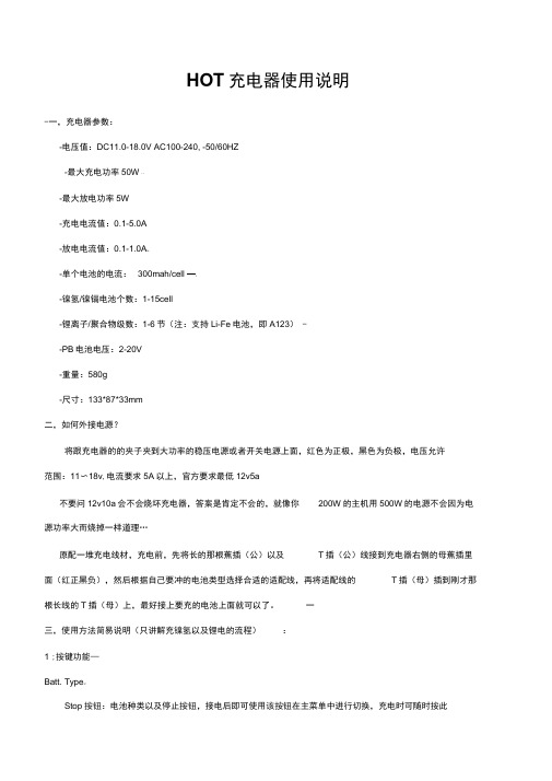
HOT充电器使用说明-一,充电器参数:-电压值:DC11.0-18.0V AC100-240, -50/60HZ-最大充电功率50W * U-最大放电功率5W-充电电流值:0.1-5.0A-放电电流值:0.1-1.0A%--单个电池的电流:300mah/cell —Z-镍氢/镍镉电池个数:1-15cell-锂离子/聚合物级数:1-6节(注:支持Li-Fe电池,即A123) --PB电池电压:2-20V-重量:580g-尺寸:133*87*33mm二,如何外接电源?将跟充电器的的夹子夹到大功率的稳压电源或者开关电源上面,红色为正极,黑色为负极,电压允许范围:11〜18v,电流要求5A以上,官方要求最低12v5a不要问12v10a会不会烧坏充电器,答案是肯定不会的,就像你200W的主机用500W的电源不会因为电源功率大而烧掉一样道理…原配一堆充电线材,充电前,先将长的那根蕉插(公)以及T插(公)线接到充电器右侧的母蕉插里面(红正黑负),然后根据自己要冲的电池类型选择合适的适配线,再将适配线的T插(母)插到刚才那根长线的T插(母)上,最好接上要充的电池上面就可以了。
一三,使用方法简易说明(只讲解充镍氢以及锂电的流程):1 ;按键功能—Batt. Type%“Stop按钮:电池种类以及停止按钮,接电后即可使用该按钮在主菜单中进行切换,充电时可随时按此键停止;…Dec. / I nc. 一< Status >按钮:减小以及增加按钮,设置各种数值时Dec.是减小,Inc.是增加,充电时按这两个按钮以浏览电池不同信息;-Start-Enter按钮:开始以及确定按钮。
接通电源,即显示主菜单,此时可以按Batt. Type / Stop按钮, 在主要的几个菜单中进行切换,它们是:bs一….Program SelectLiPo BATT对锂电系列进行充电的主菜单X_一Program SelectMiMH BATT —对镍氢电进行充电的主菜单-Program SelectNiCd BATT对镍镉电进行充电的主菜单Program SelectPb BATT充Pb电的主菜单一Program SelectSave Data™- —■保存设定数据菜单-Program SelectLoad Data ■ ~…-加载数据菜单一User SetProgram->使用者设定菜单2;锂电充电;1];开机后显示主菜单:Program SelectLiPo BATT按Start / Enter按钮确定屏幕显示LiPo CHARGE* *A*.*V(*R) _这个是锂电充电,非平衡充,不推荐所以要继续按Inc. >,屏幕显示:LiPo BALANCE*.*A *.*V(*S)这个就是传说中的锂电平衡充电功能了,我们要用的就是平衡充电,所以要在这里进行如下操作:按Start / Enter,A前面的数字闪烁,按Dec.<或者Inc. >改变改数值大小,这个是充电电流选择,锂聚合物电池最多不可超过1c,也就是4400mah电池最高用4.4A,2200mah电池最高用2.2A,这样类推;建议保守点用0.5c,即4400mah电池用2.2A,依此类推Dec.<减小该数值,Inc. >增加该数值—按Start / Enter,V(*S)前面的数字闪烁,按Dec. <或者Inc. >改变改数值大小,这个是选择电池额定电压,为3.7的倍数,车用电池一般为7.4v,即2S (每3.7v=1S),长按Start / Enter,出现如下屏幕:…Battery CheckWait...-c, @% }如果电池连接不正确,则显示:CONNECTION BREAK如连接正确,则显示:上行:R: *SER S: *SER (说明一下:R: *SER是指充电器自动检测到的电池节数,S: *SER是你设置的电池节数,如果数值不等,请不要开始充电,以免损坏电池,一……下行:CANCEL(STOP)与CONFIRM(ENTER)来回切换,此时按Start / Enter 开始充电,按Batt. Type / Stop取消充电,返回设置界面-充电界面:Li*S *.*A * **VCHG第一行:锂电节数,即时充电电流,即时电池总电压 第二行:充电指示,充电耗时,充进的电量数 充满之后显示:FULL (后面还有一串英文以及数字) ***充电过程中可随时按 Batt. Type / Stop 按钮停止充电-***充电过程中壳随时按 Start / Enter 按钮改变充电电流,改变后记得再次确认即可 ***充电过程中可随时按 Inc. >观看各节电池单独电压 “1- ***充电过程中可随时按 Dec. <观看各设定参数2.)放电7x选择LiPo DISCHARGE 功能,界面:%-LiPo DISCHARGE操作方法跟充电一样,设置好放电电流和放电截至电压即可,电压为6.0V (2S )■NLiPoCHARGE / LiPo FAST CHG 是锂聚合物电池充电/锂聚合物快速充电,为锂电电芯有明确的电压限制,所以是要求使用平衡充电器进行电压平衡充电,以防止某片电压偏低而导致另一片电压过高而出现危险情况 一LiPo STORAGE 功能是用于保存锂电,如果锂电长期不使用,请将锂电充满电后,使用这个功能,将 电压放至锂电的长期保存电压即可,使用方法与充电方法雷同,只是放电电流最大只有 1A3;镍氢电池 -1.)充电一_主菜单时按 Batt. Type / Stop 选择到: PROGRAM SELECT NiMH BA TT这个就是镍氢电池充电模式,按 Start / En ter ,显示:NiMH CHARGE Man*****•*A*.*V(*S)3的倍数级增减,7.4v 锂电请设为CURRENT *.*A按Start / Enter, A前面的数字闪烁,按Dec. <或者Inc. >改变改数值大小,这个是充电电流选择,镍氢电充电电流说明书上是1C〜2C,不过我们一般认为1C〜1.5C会比较好点,改变强制充电电流与自动充电电流控制-NiMH CHARGE Man-CURRENT *.*A-在这个开始前的充电电流选择界面,HOT默认是手动充电电流即后面是Man字样,在该种充电方式下,充电器会按照你所设置的充电电流进行充电,即强制使用你所设置的充电电流,这样并非好事,因此HOT亦可以改变为自动充电电流控制。
蓄电池充电操作规范
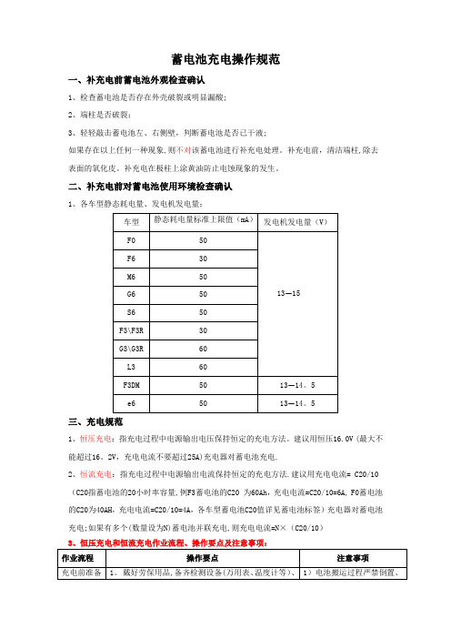
蓄电池充电操作规范一、补充电前蓄电池外观检查确认1、检查蓄电池是否存在外壳破裂或明显漏酸;2、端柱是否破裂;3、轻轻敲击蓄电池左、右侧壁,判断蓄电池是否已干液;如果存在以上任何一种现象,则不对该蓄电池进行补充电处理。
补充电前,清洁端柱,除去表面的氧化皮。
补充电在极柱上涂黄油防止电蚀现象的发生。
二、补充电前对蓄电池使用环境检查确认1、各车型静态耗电量、发电机发电量:三、充电规范1、恒压充电:指充电过程中电源输出电压保持恒定的充电方法。
建议用恒压16.0V (最大不能超过16。
2V,充电电流不要超过25A)充电器对蓄电池充电.2、恒流充电:指充电过程中电源输出电流保持恒定的充电方法.建议用充电电流= C20/10 (C20指蓄电池的20小时率容量,例F3蓄电池的C20 为60Ah,充电电流=C20/10=6A, F0蓄电池的C20为40AH,充电电流=C20/10=4A,各车型蓄电池C20值详见蓄电池标签)充电器对蓄电池充电;如果有多个(数量设为N)蓄电池并联充电,则充电电流=N×(C20/10)3、恒压充电和恒流充电作业流程、操作要点及注意事项:按照《蓄电池充电记录表》记录,见表一;2. 请确保充电机运转正常;3。
对需补充电的电池记录好电池编号、电池开路电压;4。
如有多块电池需要共同充电,请将待充电池进行分组,要求电压在12V 以上的分为一组,11V—12V 分为一组,电压低于11V 分为一组。
磕碰,轻拿轻放.2)充电前请观察透气孔处是否畅通,如被堵住请清理。
电池连接 1. 需充电的电池为单只时,直接将电池连接在充电机正、负极输出端;2。
多个电池需共同充电时,电池用连接线逐只并联(电池之间要求正正、负负相连),然后充电机正、负极输出端连接于任意一块电池的正、负极输出端即可.1)注意正确识别电池正、负极(电池上盖上有明确的“+”“—"标识),以免电池极性充反导致车辆电器元器件损坏;2)多个电池共同充电时严禁将电池之间的连线接错造成电池短路充电 1. 查电池的连接极性是否正确,连接线是否已连接可靠,无虚接现象;2.恒压充电2。
- 1、下载文档前请自行甄别文档内容的完整性,平台不提供额外的编辑、内容补充、找答案等附加服务。
- 2、"仅部分预览"的文档,不可在线预览部分如存在完整性等问题,可反馈申请退款(可完整预览的文档不适用该条件!)。
- 3、如文档侵犯您的权益,请联系客服反馈,我们会尽快为您处理(人工客服工作时间:9:00-18:30)。
蓄电池充电器蓄电池充电机密特CX PRO 25
多种蓄电池技术
只用一次投资就能为不同技术的蓄电池充
电(包括铅酸,AGM/Spiral和GEL)
保养维护用充电机
ECU刷新期间专用“蓄电池调压”模式和车
辆的维修保养。
在ECU匹配(coding)和编
程(刷新程序)期间,不间断的纯净的电压非
常重要。
C2充电技术满足不同修理厂的需要
灵活可变的设备满足各种条件下的充电和
供电
全面的蓄电池维护中心
Midtronics C2(受控充电)技术。
C2技术采
用高频技术并结合智能充电曲线使充电工作安全,快速和简单。
根据被测试的蓄电池技术(包括铅酸,AGM/Spiral和GEL)采用不同的充电曲线。
应用
汽车/轻卡,大功率/商用车,军车和船舶。
功能特点:
充电接受程度/ 充电正确性
与传统充电机不同的是,TRIV BC CX Pro 能够智能地检测充电接受能力。
坏电池将不会进行充电;安全的充电时间以及避免危险情况发生。
充电操作简单,只需要连接好充电夹,打开电源然后选择正确的蓄电池技术(AGM/Spiral, Lead-Acid Ca/Ca或Gel)就可以了。
编程和维修保养工作
在进行车载诊断工作期间,如ECU编程,匹配或刷新,汽车上的电子部件不断消耗蓄电池电量。
车辆进厂维修时,蓄电池常常已经部分放电,要再放电就会导致更多的问题。
在供电模式下,TRIV BC CX Pro可以充当电源供电而不会消耗电池的电量(诀窍:这种模式也可以用在更换蓄电池时)。
安装优点
采用先进的设计和技术,因此重量轻,外形小。
可安装在任何地方,如安装在举升机上,墙上,诊断中心台架,工具柜等。
采用CX Pro的维修工位可以完成新型维修工作。
Lead-Acid, AGM, Spiral和GEL充电曲线
脉冲(充电后期)模式
充电接受程度
存储器保全
增强电压
自动供电模式
可拆卸电缆
ECU编程电源
规格:
型号:TRIV BC CX PRO 25
保修:Midtronics标准2年保修
应用:汽车,农机和船舶用12V铅酸/ Ca-CA (flooded), AGM, Spiral 和GEL蓄电池
工作范围:0 - 240 Ah
外部电源:230 volts AC, 50 Hz / 16A
显示:1个状态LED等;4个功能LED灯
工作温度:-20 to 45° C / 0 to 113° F
外壳材料:铝合金
产品尺寸:205 mm x 185 mm x 100 mm (8" x 7.3" x 3.9")
产品重量:2.5 kg / 5.5 lb。
