BE23控制器操作说明
赋安三合一火灾报警控制器使用说明书V

眉板(空白单元) 主控显示单元(含主控液晶显示及指示灯) 主控键盘单元 多线及打印机单元(含多线控制单元及打印机) 空白单元
尾板(空白单元)
眉板 液晶显示屏、指示灯、操作按键 打印机
1.2.3 AFN80火灾报警控制器
液晶显示屏 指示灯
操作按键 打印机
6 远见 创新 精专 信实
火灾报警控制器使用说明书
机号、
类型、回路-地址、显示关系
设备类型、时间、位置描述
机号、类型(序号)、回路-地址、显示关系
设备类型、时间、位置描述
事件类型:
序号、类型、机号、回路-地址、显示关系
设备类型、时间、位置描述
火警:002 启动:020 反馈:000 故障:221 屏蔽:000
手动
2009/05/25 09:19:03
9
2.1
标志及说明 ‥‥‥‥‥‥‥‥‥‥‥‥‥‥‥‥‥‥‥‥‥‥‥‥‥‥
9
2.2
显示界面说明 ‥‥‥‥‥‥‥‥‥‥‥‥‥‥‥‥‥‥‥‥‥‥‥‥‥
9
2.3
开、关机 ‥‥‥‥‥‥‥‥‥‥‥‥‥‥‥‥‥‥‥‥‥‥‥‥‥‥‥
9
2.4
火警信息与处理 ‥‥‥‥‥‥‥‥‥‥‥‥‥‥‥‥‥‥‥‥‥‥‥‥
10
2.5
故障信息与处理 ‥‥‥‥‥‥‥‥‥‥‥‥‥‥‥‥‥‥‥‥‥‥‥‥
火警发生时,根据主机报出的火警信息找到报警的具体位置,确认是否真正发生火灾; 如果确认是发生火灾,则应立即执行如下措施(或执行用户制定的火灾紧急处理措施):启动火灾 现场的声光设备及广播,通知现场人员进行疏散;向上级汇报或电话报警;通知相关专业人员进行灭火 或控制火情;如果主机处于手动状态,可按【火警确认】键或通过菜单将主机改为自动状态,以便主机 按照预设的联动关系启动设备,也可启动手动控制单元启动相关设备。 如果确认是误报火警,则对主机进行消音,检查误报原因且排除,对主机进行复位,使之恢复到正 常工作状态。如果是报警设备损坏,可先将其屏蔽,然后通知我公司的技术服务人员或专业维护保养单 位的技术人员进行处理。
BE23操作使用说明书

BE23操作使用说明书BE23自动起动模块是被用于自动起动和停止发动机,保护发动机和发电机并且显示发电机组的最重要数据例如电量和发动机温度和油压。
为满足IP 54 保护要求,由按钮代替锁匙开关。
通过一个接口为PC机进行遥控编程和显示值。
特征!●机组和 3 相发电机组控制,监控及保护!●紧凑的 96 x 96 mm DIM工业用的壳体!●工作温度范围从-30 O C到 +65 O C !●4位数字显示, 12 指示发光二极管和 8 按钮操作!●自动,手动或全遥控的操作,外接锁匙开关!●显示kVA , kW , Vac , Vdc , Aac , Hz , rpm ,运行小时,报警!●通过PC进行监视,控制和编程(遥远) !●简易的介面来自模似传感器和数字开关!●扩大的温度范围和 IP 54 保护!●IP 54 保护!●选择:插件 RS 232 接口为直接和遥控BE23 OEM指导手册重要提示:由于产品不断发展与改良的政策,本公司保留在没有通知的情况下,更改的权力。
1.00建立步骤--------------------------------------------------------------------------------------31.01 起始设定------------------------------------------------------------------------------31.02 接线安装指导--------------------------------------------------------------------------32.00 使用面板--------------------------------------------------------------------------------------42.01 显示和按钮----------------------------------------------------------------------------42.02 固定状态灯----------------------------------------------------------------------------43.00“手动”操作指导-------------------------------------------------------------------------------43.01 BE23初次建立--------------------------------------------------------------------------43.02 手动起动------------------------------------------------------------------------------43.03 手动停车------------------------------------------------------------------------------43.04 负载控制------------------------------------------------------------------------------53.05 “OFF”操作模式-------------------------------------------------------------------------54.00 “自动”操作指导--------------------------------------------------------------------------------5 4.01 BE23建立-----------------------------------------------------------------------------54.02 自动操作模式选择----------------------------------------------------------------------54.03 使用遥控起动特性----------------------------------------------------------------------54.04 使用AMF特性--------------------------------------------------------------------------54.05 在”AUTO”状态下警报监测---------------------------------------------------------------64.06 在”AUTO”状态下停车-------------------------------------------------------------------64.07 在”AUTO”状态下,定时和设定------------------------------------------------------------65.00 显示菜单特征-----------------------------------------------------------------------------------6 5.01 引擎菜单------------------------------------------------------------------------------65.02 编程菜单------------------------------------------------------------------------------75.03 功率菜单-----------------------------------------------------------------------------105.04 “V/A/HZ/H”菜单-----------------------------------------------------------------------105.05 警报菜单-----------------------------------------------------------------------------105.06 编程指导-----------------------------------------------------------------------------116.00 报警表和描述 ---------------------------------------------------------------------------------11 6.01 油压警报和停车-----------------------------------------------------------------------116.02 温度警报/停车------------------------------------------------------------------------126.03 起动失败-----------------------------------------------------------------------------126.04 电池电压警报-------------------------------------------------------------------------126.05 “外接停车输入3”停车-----------------------------------------------------------------126.06 超速/低速停车------------------------------------------------------------------------126.07 低/高频率停车------------------------------------------------------------------------136.08 低燃油位停车-------------------------------------------------------------------------136.09 低燃油位警报-------------------------------------------------------------------------136.10 功率”KVA”警报停车--------------------------------------------------------------------136.11 过电流停车----------------------------------------------------------------------------136.12 超/低电压停车-------------------------------------------------------------------------136.13 皮带故障停车--------------------------------------------------------------------------146.14 交流发电机故障停车--------------------------------------------------------------------146.15 “辅助警报输入4”停车------------------------------------------------------------------146.16 储存“Err”信息------------------------------------------------------------------------147.00 常用规格---------------------------------------------------------------------------------------14 7.01 静态输出-------------------------------------------------------------------------------147.02 发电机电压输入特性---------------------------------------------------------------------147.03 电流互感器输入特性---------------------------------------------------------------------157.04 数字的输入特性-------------------------------------------------------------------------157.05 油压模拟输入特性-----------------------------------------------------------------------157.06 温度模拟输入特性-----------------------------------------------------------------------157.07 引擎运行特性---------------------------------------------------------------------------157.08 转速传感器输入特性---------------------------------------------------------------------167.09 燃油位模拟输入特性---------------------------------------------------------------------167.10 交流发电机(电池充电)监测---------------------------------------------------------------168.00 正时表/参数 ------------------------------------------------------------------------------------16 8.01 预热时间-------------------------------------------------------------------------------168.02 起动次数-------------------------------------------------------------------------------168.03 电起动马达插入时间---------------------------------------------------------------------168.04 起动间隔的脉冲时间---------------------------------------------------------------------168.05 警报延迟时间---------------------------------------------------------------------------168.06 冷却时间,起动/停车延时,暧车------------------------------------------------------------169.00 配线图-------------------------------------------------------------------------------------------1710.00 串行接口/监测软件-------------------------------------------------------------------------------1711.00 问题解答----------------------------------------------------------------------------------------1712.00 测量校对----------------------------------------------------------------------------------------1812.01 小时计清除-----------------------------------------------------------------------------1813.00 术语的定义--------------------------------------------------------------------------------------1914.00 端子内容----------------------------------------------------------------------------------------1915.00 背面视图和连接----------------------------------------------------------------------------------2116.00 前面板描述--------------------------------------------------------------------------------------2217.00 软件升级----------------------------------------------------------------------------------------23警告:该模块有故障时应退回BERNINI公司进行修理, 任何对模块内的线路改动将失去保质.1.00 建立步骤下列步骤是对BE23 操作过程进行检查或修改。
Smart Digital Earth Tester AET 23 使用手册说明书

Smart Digital Earth TesterAET 23 Users ManualAET 23 USERS MANUAL1ContentChapter Page25691011181. Safety Instructions2. Characteristics3. General Specifications4. Product outlook & accessories5. Preparation before measurement6. Measurement Operation7. Maintenance & RepairAET 23 USERS MANUAL21.Safety InstructionsThis operation manual includes the user guidance and safety instruction when using the tester, please read it before using. Before using the Tester, please read and understand the operating manual including the content. Keep the operating manual properly, and let it easy to get it for reference during the process of testing.When using the Tester, user must follow the testing procedure as mentioned in the operating manual.Careful reading the operating manual regarding the safety information and it is content.Must be followed all the related safety instructions, otherwise it may cause accidents or damage the Tester.AET 23 USERS MANUAL3Danger identifies conditions and actions that most likely pose hazard(s)or die.Warning identifies conditions and actions that will pose hazard(s) ordie.Caution identifies conditions and actions that will pose hazard(s) ordamage the Tester.Safety sign " "has 3 meaning in this manual, user has to pay attention to this sign" "for operation.DangerDo not use the Tester around explosive environment, which may cause fire and explosion.Do not use the Tester in wet environment or do not make any connection work when your fingers are wet.Do not apply the load more than the Tester capacity or range.Do not open battery compartment while testing.AET 23 USERS MANUAL4 WarningDo not use the Tester if it is damaged or metal part is exposed.Do not disassemble the tester un-intentionally. If it needs repair, please contact our after-sales services or our agents.Do not change battery or open battery compartment when the Tester is wet. Soft cloth should be used to dry it first, and then carry on.Make sure the Tester is turned off when changing battery or opening the battery compartment.CautionEnsure test lead probe insert into the corresponding port before measurement. Take the battery out from the Tester if it is not used for a long time.Do not expose the Tester in extreme temperature and wet environment.Soft cloth and mild detergent should be used to clean the surface of the Tester when servicing. No abrasive and solvent should be usedDry the tester before storing if it is wet.identifies AC[AC] GroundingAET 23 USERS MANUAL52.CharacteristicsThe Tester is using micro controller with high accuracy and reliability; it can measure every electric wire, electric installation, anti-thunder equipmentís earth resistance value of those earth system. Also, it can carry earth voltage measurement. (Note:the Tester should not be used outdoor hazard environment, like raining, thunder etc.)2.1 With backlight display and battery check function.2.2 Data logging for 20 sets of data.2.3 With auto switch-off save energy function.2.4 Precision 3-Wires Testing and Simple 2-Wires Testing.2.5During earth voltage testing, if C port or E port don't contact properly, LCD display will show"- - - - "indication.2.6 Over-range Display"OL"indication.2.7 Double insulation or reinforced insulation safety manufacturing.AET 23 USERS MANUAL63.General Specifications3.1Operating temperature and Relative humidity(20 5 & 75%RH):3.2 Application standard:IEC 61010-1 CATIII 600V Polluting Grading: Grade II IEC 61557-1,5 IEC 61010-2-31AET 23 USERS MANUAL73.3 Measure methods:(1) Earth Voltage Testing:average respond(2) Earth Resistance Testing : testing signal frequency : around 820Hz,current : 20 position around 3.2mA3.4 Maximum operating accuracy: Maximum operating accuracy within measure range:( 30%) 20 : 5.00 ~20.00 200 : 20.0 ~200.0 2000 : 200 ~20003.5 Working condition:Temperature:5 ~40 Relative humidity: 80%RH(no fog) Height above Sea Level: 2000 meters3.6 Storage condition:Temperature:-20 ~60 Relative humidity: 75%RH(no fog)AET 23 USERS MANUAL 83.7 Power source:[1.5V Alkaline Battery (AA)*6]3.8 Overload protection:Earth Resistance:200 Vac (10 seconds) Earth Voltage:400 Vac (30 seconds)3.9 Insulation Resistance :The insulation impedance between measure circuit and housing is not less than 20M .3.10 Product size:160mmx70.5mmx100mm.3.11 Product Weight:around 560g.3.12 Accessories:Green test lead 5 meter Yellow test lead 10 meter Red test lead 20 meter Auxiliary earth stakes One plug test lead with alligator clip 1.5V Alkaline Battery (AA)Carrying Bag English manual 1 piece1 piece1 piece2 pieces1 set6 pieces1 set1 pieceAET 23 USERS MANUAL94. Product outlook & accessories:(figure 1)figure 1LCD DisplayLIGHT/LOAD buttonHOLD/SAVE buttonTEST buttonON/OFF functionInput terminalsStandard 3-Wires test leadsSimple 2-Wires test leadsAuxiliary earth stakes 231456789AET 23 USERS MANUAL105.2 Test leads connectionMake sure all the test leads are firmly connected to the Tester input terminals; test leads do not firmly connect will affect the accuracy of measuring value.5. Preparation before measurement5.1 work properly.AET 23 USERS MANUAL116. Measure method6.1 Precision Measurement (using standard test leads for measurement):a. place 2 ground stakes in earth/dirt. Minimum distance between earth electrode(E), probe(P) and auxiliary earth (C) should be 5-10 meter apart, as below connection figure 2:(Attention:ensure the ground stakes in the moisture soil. If the soil is too dry, it need to fill-in sufficient water. Rock or sand also needs moisture before testing. If the testing site is inside the urban city with concrete cover which is hard to put in the ground stakes, it can use 25cm X 25 cm two steel plates (or using the existing ground stakes) place horizontally in concrete surface, and cover by moisture towel with sufficient water, replace measurement earth, it still can make measurement in general situation.)AET 23 USERS MANUAL12figure2C: auxiliary electrode P: potential electrode E: earth electrodeAET 23 USERS MANUAL13b. Earth Voltage Testing:Select function OFF to EARTH VOLTAGE, LCD display will show voltage, connect test leads in V and E, then connect to the testing point, LCD display will show earth voltage value (Attention:measure earth voltage does not need to press TEST button). If the measuring value>10V, then it need to switch-off all the related voltage equipment. Wait until the earth voltage decrease, and then do it again. Otherwise, it will affect the accuracy of earth resistance.Warning:Earth voltage testing only work in V and E, C and P connecting cable must be separated. Otherwise, it will cause danger and damage the Tester.c. Earth Resistance Testing:Select function OFF to EARTH RESISTANCE 2000 (Maximum),press"TEST"button, LCD display will show earth resistance value. If the resistance value <200 ,then select function from OFF to earth resistance 200 ,LCD display will show earth resistance value. If the resistance value <20 ,then select function from OFF to earth resistance 20 ,LCD display will show earth resistance value; Of course, you can follow the other selecting order for testing. In summary, you need to select the best measurement position to measure for getting the best accuracy.AET 23 USERS MANUAL 14press"TEST"button, the button's light will be on, which shows the Tester is in measurement.(Note:when C or E does not connect properly, auxiliary earth resistance or earth resistance excess the load (like 20 excess around 14K ),or testing terminal open circuit,LCD display will show"- - - - ",then it need to double check the connection parts, whether soil is too dry, whether auxiliary earth stakes is close to earth.)When the earth resistance testing point over the selected measuring range, meanwhile the selected 20 position less than around 14K , or 200position less than around 26K , or 2000 position less than around 78K ,LCD display will show "OL"(overload). Warning:If the auxiliary earth stake is banning or touch the other materials, it will affect the reading. When connect the test leads,it must clean the auxiliary earth stake. If the auxiliary earth stake value is too large,it also cause the deviation in reading.d. The tester should be switch - on when press the button and select the function key.Auto switch off after around 10 minutes for power save(except earth resistance testing function on).e. Backlight on:while testing in poorly lighted area, it needs backlight press "Light/Load"button,backlight function will be on and LCD display the corresponding sign. Press"Light/Load"button again, then it will switch-off backlight function.AET 23 USERS MANUAL15f. Hold function:while testing, press slightly"Hold/Save"button,save data function will be on, the corresponding testing value will be saved and LCD display the corresponding sign. Press slightly"Hold/Save"button again, then it will cancel this function.g. Storage function:1.storage data press"Hold/Save"button for around 2 seconds. Storage function will be on and save the corresponding data. Press "Hold/Save"button once again to save the 2nd data; press"Hold/Save"button again to save the 3rd data...,For switch-off this function, press"Hold/Save"button for around 2 seconds.2.Read data press"Light/Load"button for around 2 seconds, it will show address serial number 01 saved data. Press"Light/Load"button once again to show the address serial number 02 saved data...until the 20th saved data. If you want to return back the previous saved data, press "Hold/ Save"once; (In the situation"Hold/ Save"button"Light/Load"button (slightly press) is working like up and down button). For switch-off this function, press"Light/Load"button for around 2 seconds.3. Clear saved datapress"Hold/Save"button and "Light/Load"button simultaneously, then switch-on the Tester, LCD display will show"C L .",Meanwhile, all the data in the storage will be deleted(20 sets of data or part ofdata can be deleted).AET 23 USERS MANUAL166.2 Simple measurement(use simple 2-Wires test leads for measurement): This method will be used when the auxiliary earth stake cannot be used. Use the expose earth resistance object from the ground as earth, like metal water bath, water pile, wire ground, building earth, also can use 2-wires test leads method (E and P&C terminals).Connection as figure 3:AET 23 USERS MANUAL17When using this method, P and C have already connected together.AET 23 USERS MANUAL187. Maintenance & Repair7.1 Maintenance 7.1.1 Replacing battery and repair(please see figure 4) After low battery indicatorshow, replacing battery immediately as follows:figure 4AET 23 USERS MANUAL19 a. switch-off the Tester and remove all the test leads.b. release the screw in bottom part,and open battery compartment.c. Replacing all old battery (6) with new battery.d. After replacing the battery, rejoin the battery compartment and firmly screw. Remove all the batteries if the Tester do not use for a long time, so that it avoid the leakage and corrosion in the battery compartment. 7.1.2 Cleaning the TesterSoft cloth and mild detergent should be used to clean the surface of the Tester, because solvent will corrosive the display.7.1.3 Must be avoiding moisture.7.2 Repair7.2.1 Contact our after-sales service department or agents when the following thing happens:a. The Tester is being damage.b. LCD display abnormal.c. Unreasonable deviation when in normal use.d. Buttons do not function properly and confusion.7.2.2 when the Tester needs repair, please bring it to the professional technician or authorized repair department for repair.**END**AET 23 USERS MANUAL20This operating manual is subject to change without notice.AET 23 USERS MANUAL21Marketed by:RISHABH INSTRUMENTS PVT.LTD.F-31, MIDC, Satpur, Nashik-422 007,India.Tel.: +91 253 2202028, 2202202 Fax : +91 253 2351064E-mail:India:*********************.inInternational:*************************.inwww.rishabh.co.in。
Citronic活动跨越CX23和CX34用户手册说明书

Active CrossoversCX23 170.929CX34 170.932User ManualFeatures:∙Linkwitz-Riley crossover filters∙Mono/Stereo operating modes∙Switchable Phase Invert∙Switchable Butterworth 40Hz low cut∙Balanced or unbalanced XLR connectionsIntroduction:Thank you for choosing a Citronic active crossover. This product has been designed to give accurate control for a multi-amplifier sound reinforcement system. In order to achieve the best results from this equipment and avoid damage through misuse, please read and follow these instructions and retain for future reference.Warning:To prevent the risk of fire or electric shock, do not expose any part of the unit to rain or moisture.If liquids are spilled on the surface, stop using immediately, allow unit to dry out and have checked by qualified personnel before further use.Avoid impact, extreme pressure or heavy vibration to the unit.There are no user serviceable parts inside the crossover – refer all servicing to qualified service personnel.Safety ∙ Check that the supplied mains lead is in good condition and the supply voltage is correct. ∙ Ensure signal leads are of good condition and connected to appropriate inputs/outputs ∙ Do not allow any foreign particles to enter the console through control apertures or connector aperturesPlacement ∙ Keep out of direct sunlight and away from heat sources. ∙ Keep away from damp or dusty environments. ∙ When rack-mounting, avoid placing heavy units above the unit and ensure all connectors are accessibleCleaning ∙ Use a soft cloth with a neutral detergent to clean the casing as required ∙ Use a soft brush to clear debris from the control surface ∙ Do not use strong solvents for cleaning the unit.Front PanelRear PanelWhat is an Active Crossover?A crossover is a device for separating the high frequencies from the low frequencies in a sound reinforcement system. Passive crossovers exist in speaker cabinets to split the high and low frequencies of an amplifier output and feed into the appropriate speaker components. This is usually necessary in cabinets with separate low frequency and high frequency speaker components (woofers and tweeters) but can be inefficient because it operates on the high energy output from an amplifier and dissipates much energy as heat.Active crossovers operate before the amplifier(s) stage, where the signal is typically less than a Volt, affording accurate and efficient separation of the component frequencies. Essentially, an active crossover splits each audio signal into 2, 3 or even 4 sets of frequencies, feeding each into a separate amplifier, which in turn powers a specific speaker component. This allows each speaker component to handle just the type of sound it produces most efficiently, avoiding wasting energy from the amplifier. Configuration∙ The CX23 can be configured as a 2-way stereo or 3-way mono crossover∙ The CX34 can be configured as a 2-way stereo, 3-way stereo or 4-way mono crossoverThe connection and operating mode depends upon the type of amplifier configuration (bi-amp, tri-amp or quad-amp)ConnectionIn all configurations, the output(s) (left and right or mono) from the signal source (usually the main mixing console) are connected to the input(s) of the crossover. All connections are balanced (or unbalanced, if preferred) and should be connected using good quality XLR leadsIn a bi-amped system, the LOW (or LF SUM) outputs are connected to the inputs of the power amplifier which will drive the sub cabinets and the HIGH outputs are connected to the inputs of the power amplifier which will drive the mid-top cabinets.In a tri-amped system, the LOW (or LF SUM) outputs are connected to the inputs of the power amplifier which will drive the sub cabinets, the MID outputs are connected to the power amplifier which will power the main drivers of the mid-top cabinets and the HIGH outputs are connected to the inputs of the power amplifier which will drive the high frequency drivers in the mid-top cabinetsIn a quad-amped system, the LOW (or LF SUM) output is connected to the input of the power amplifier which will drive the sub cabinets, theLOW-MID output is connected to the power amplifier which will power the dedicated mid-range cabinets, the HIGH-MID outputs are connected tothe power amplifier which will power the main drivers of the mid-top cabinets and the HIGH outputs are connected to the inputs of the power amplifier which will drive the high frequency drivers in the mid-top cabinetsConnect the crossover to mains power via the supplied IEC lead, ensuring the supply voltage is correct.There may be slight variations from these set-ups but all follow the same basic principles.OperationIt may help to know the frequency responses of all speaker components in the system or alternatively, crossover setup can be done by ear. The main parameters are the crossover frequencies and gain amounts for each output.Select the MODE that the crossover is to be used from the buttons on the rear panel. Each mode gives controls different parameters, so care must be taken to read the control’s function printed on the front panel for the given mode.If tri-amped or quad-amped systems are used, the Crossover frequency multiplier should be pressed in for MID/HIGH or HIGH-MID/HIGH crossover points. This causes the frequency control to operate at a much higher frequency (10x) which is more suited to the division between mid and high frequency drivers.With all amplifiers switched off, turn down all GAIN controls and switch on the crossover. Switch on amplifiers and turn up the volume of each output. Play the signal from the sound source (mixer) through the crossover and gradually increase the gain controls of each section. Gradually rotate the XOVER FREQ (crossover frequency) control for LOW/HIGH or LOW/MID or LOW/LOW-MID until the desired bass character is achieved. This is the control that determines the highest frequencies that will be fed into the sub cabinets. Lower crossover settings will need higher gain settings to compensate for frequencies that are not fed into the sub cabinet (filtered out).Repeat the crossover frequency setting process for LOW-MID, MID, HIGH-MID and HIGH frequencies (where appropriate) adjusting the crossover frequencies to suit each driver and gains to balance the range of frequencies.Occasionally, frequencies from some cabinets in stereo setups can have opposing phase characters. Also, some drivers may sit physically further back from others. This can cause cancellation of frequencies. To deal with this, the Citronic crossovers have Phase switches, which can be pressed in to invert the phase of the signal (push becomes pull and vice versa). This can be tested by trial and error to hear if pressing the switch in has a beneficial effect to the volume level of that particular frequency.To further help avoiding phase cancellation, the LOW can be “summed” to a mono signal (LF SUM), eradicating differing signals in the lower registers of a stereo signal.Remember to turn down amplifiers and switch off prior to powering down the crossover to avoid loud noises in the sound system.Note: for further troubleshooting, refer equipment to qualified service personnel for testing© Citronic 2011。
格力超薄风管机使用安装说明书
13
6 设定温度显示
14
7 化霜状态显示
15
8 定时时间显示
16
遥控接收头
模式键
设定温度增加键 设定温度减少键 风速键 睡眠键 定时键 开/关键
3
线控器操作指南
1) 开/关机(图 2) 按下开/关键,本机组将会启动。 再一次按下开/关键,本机组将停止。
2)风扇控制(图 3)(图中所示为有关显示区域,以下同) 每一次按下风扇控制键时,风扇速度按如下顺序变化:
送风、自动模式无睡眠功能。
图5
5)运行模式设置(图 6) 每一次按下本键,操作模式按如下顺序变化:
→制冷→除湿→送风→制热→自动
制冷模式时,制冷显示 将点亮,温度必须设定成比现
自动
在的环境温度低。如果设定成比现在环境温度高,本机将
不会进入制冷方式而将只会有风扇动作。
化霜
除湿模式时,除湿显示 将点亮。内风机在一定温度范
→低速→中速→高速→自动→
除湿模式中:风扇速度会自动设定为低速。
3)温度调节(图 4) 按下温度调节键,
▲:用以使设定温度增加; ▼:用以使设定温度减少。 (按下一次本键时,温度将以 1℃为单位增加或减少。)
各种模式下温度设定范围:
制热 -------- 16℃~30℃ 制冷 -------- 16℃~30℃ 除湿 -------- 16℃~30℃ 送风 -------- 不能进行温度的设定 自动 -------- 不能进行温度的设定
14
机
室内机组水平检验
15
安
冷凝水管的安装与测试
16
装
连接管选配及其保护层的安装
17
指
线控器的安装
电动滑板车控制器
电动滑板车控制器随着滑板运动在欧美乃至世界范围内的流行,一种更新奇、更刺激的动力滑板车很快得到了人们的喜爱。
除了在欧美,电动滑板车在我国也有很好的市场发展前景,滑板车已成为中国一个新兴的庞大产业。
1.控制器的工作原理电动滑板车控制器是滑板车的核心部件, 它的任务是在驾驶者的控制下, 高效率地将蓄电池的能量转化为电动机的动能。
控制器的优劣直接影响到整车调速的平滑性、响应的快速性等。
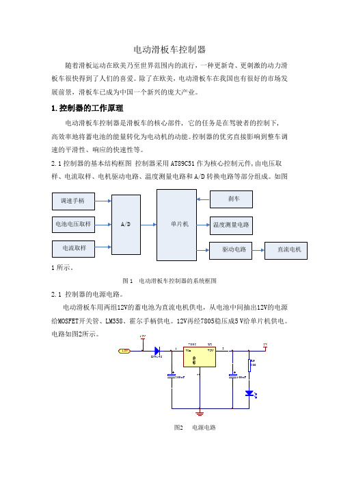
2.1控制器的基本结构框图控制器采用AT89C51作为核心控制元件,由电压取样、电流取样、电机驱动电路、温度测量电路和A/D转换电路等部分组成。
如图1所示。
图1 电动滑板车控制器的系统框图2.1 控制器的电源电路。
电动滑板车用两组12V的蓄电池为直流电机供电,从电池中间抽出12V的电源给MOSFET开关管、LM358、霍尔手柄供电。
12V再经7805稳压成5 V给单片机供电。
电路如图2所示。
图2 电源电路2.2电压、电流测量电路电路如图所示,电池电压经电阻R2, R3分压后送至ADC0809的IN0引脚,转换成数字量再换算成电压值,当电池电压小于21V时,使P2.0脚接的红色发光二极管闪烁提醒用户电量不足,并由软件关闭PWM输出,达到保护电池的目的。
额定电压为DC24V,额定功率为200W的永磁式直流电机,效率以80%计算,其额定电流为10A左右。
控制器的限流值设定为电机额定工作电流的2.5倍,即25A。
当电流达到限流值时,减小输出PWM的占空比,从而减小电机电流,实现对电机的限流保护。
电机电流的大小通过康铜丝电阻R1(0.01Ω)两端的压降来反映,经放大器LM358(电压增益为10)放大后送至ADC0809的IN1引脚,转换成数字量。
2.3 温度测量电路当控制器处于非正常状态或电动车处于长期过载运行时,控制器的温度会升高,温度过高会使控制器损坏。
为了防止控制器温度过高,当控制器温度达到一定值时,减小输出PWM的占空比,减少控制器输出电流,以防止温度继续上升。
山洋驱动器说明
维护8.1故障检修(有报警时)-----------------------------------------8-2 8.2故障检修(无报警时)-----------------------------------------8-21 8.3用旋转开关进行速度环比例增益切换----------------------8-238.3.1概述------------------------------------------------------8-238.3.2设置过程------------------------------------------------8-23 8.4维护----------------------------------------------------------------8-24 8.5零部件检修-------------------------------------------------------8-258.1故障检修在以下的内容中, 将着力于解释每一个故障和报警的可能原因、检查方法以及检修措施。
为了避免事故发生, 在一个报警或者故障发生时, 一定要确保故障被去除并且确保系统安全后才可以重新操作。
在没有确保伺服驱动器、电机、机械装置和四周环境安全的情况下就去展开故障原因的调查是非常危险的。
详细了解故障发生时的情况将有助于缩小故障的可能范围、缩短故障检修过程。
在重现已确认的故障时务必确保这样做是安全的,并且要高度注意重现故障时的运行环境。
在更换伺服驱动器和伺服电机时,要确保没有其他的外部引起故障的因素以防止双重损坏。
在按照该手册推荐的方法进行故障检修以后若故障仍然存在,请咨询您的Sanyo Denki的经销商当报警状态显示为“8”、“F”或者“P”时,报警不能够复位。
在这种情况下应该先纠正该故障然后才能打开控制电源。
当一个报警出现时, 安放在伺服驱动器前面板上的七段LED状态显示屏就会开始闪烁, 并且报警从CN1输出。
三星 Galaxy S23 Ultra 用户手册说明书

音量键 侧键
SIM 卡托盘 扬声器
前置照相机 触摸屏
话筒 距离/ 光传感器 音量键 侧键
指纹识别传感器
SIM 卡托盘
耳机插孔/ 多功能插孔 (USB Type-C)
7
入门指南
后置照相机
后置照相机 话筒
NFC 天线 / 无线充电线圈
扬声器 通气孔
GPS 天线 闪光
主天线 话筒
8
入门指南
• 使用扬声器时,例如播放媒体文件或使用免提功能时,请勿将设备靠近耳朵。 • 请注意,不要将照相机镜头暴露于强烈的光源下,例如直射的阳光。若将照相机
13
入门指南
设置电源共享的限制
您可以设定设备以在剩余电池电源低于特定水平时停止电源共享。 打开设置,点击电池和设备维护 → 电池 → 无线电源分享 → 电量限制,然后设定限制。
减少电池消耗
设备提供各种选项,可助您节省电池电量。 • 使用设备维护功能优化设备。 • 在不用设备时,按下侧键关闭屏幕。 • 开启省电模式。 • 关闭不必要的应用程序。 • 不在使用时关闭蓝牙功能。 • 关闭需要同步的应用程序的自动同步功能。 • 减少背景灯时间。 • 降低屏幕亮度。
用户手册
SM-S911B/DS SM-S916B/DS SM-S918B/DS
Chinese. 02/2023. Rev.1.0
目录
入门指南
5 设备部位图和功能 11 为电池充电 16 Nano-SIM 卡和 eSIM 18 打开和关闭设备 19 初始化设置 20 三星帐户 21 从之前的设备传输数据 (S 换机助手) 23 了解屏幕 31 通知面板 33 截屏和录屏 34 输入文本
15
入门指南
研华 TPC-xx51T-x3BE 系列 触摸式平板电脑 用户手册说明书

用户手册TPC-xx51T-x3BE 電腦搭载Intel® Atom™ 或Intel®Celeron® 处理器的工业级触摸式平板电脑版权声明随附本产品发行的文件为研华公司2019年版权所有,并保留相关权利。
针对本手册中相关产品的说明,研华公司保留随时变更的权利,恕不另行通知。
未经研华公司书面许可,本手册所有内容不得通过任何途径以任何形式复制、翻印、翻译或者传输。
本手册以提供正确、可靠的信息为出发点。
但是研华公司对于本手册的使用结果,或者因使用本手册而导致其它第三方的权益受损,概不负责。
认可声明Intel和Atom为Intel Corporation的商标。
Microsoft Windows和MS-DOS为Microsoft Corp.的注册商标。
所有其它产品名或商标均为各自所属方的财产。
本手册适用于以下产品型号:⏹TPC-1251T-E3BE⏹TPC-1551T-E3BE产品质量保证(两年)从购买之日起,研华为原购买商提供两年的产品质量保证。
但对那些未经授权的维修人员维修过的产品不予提供质量保证。
研华对于不正确的使用、灾难、错误安装产生的问题有免责权利。
如果研华产品出现故障,在质保期内我们提供免费维修或更换服务。
对于出保产品,我们将会酌情收取材料费、人工服务费用。
请联系相关销售人员了解详细情况。
如果您认为您购买的产品出现了故障,请遵循以下步骤:1.收集您所遇到的问题信息(例如,CPU主频、使用的研华产品及其它软件、硬件等)。
请注意屏幕上出现的任何不正常信息显示。
2.打电话给您的供货商,描述故障问题。
请借助手册、产品和任何有帮助的信息。
3.如果您的产品被诊断发生故障,请从您的供货商那里获得RMA (ReturnMaterial Authorization) 序列号。
这可以让我们尽快地进行故障产品的回收。
4.请仔细地包装故障产品,并在包装中附上完整的售后服务卡片和购买日期证明(如销售发票)。
贝加莱冗余系统使用手册+V2.0
贝加莱冗余系统使用手册日期: April 10, 2015版本: V2.0We reserve the right to change the content of this manual without prior notice. The information contained herein is believed to be accurate as of the date of publication, however, B&R makes no warranty, expressed or implied, with regards to the products or the documentation contained within this document. B&R shall not be liable in the event if incidental or consequential damages in connection with or arising from the furnishing, performance or use of these products. The software names, hardware names and trademarks used in this document are registered by the respective companies.I 版本信息Table 1: VersionsII 分派信息Table 2: Distribution III 安全注意事项Table 3: Safety noticesIV 目录1介绍 (4)1.1 贝加莱的冗余方案 (4)2硬件配置 (6)2.1主站配置 (6)2.2 I/O站配置 (8)2.3第三方通讯 (8)2.3.1 POWERLINK iCN挂接通讯模块 (8)2.3.2 POWERLINK总线控制器挂接通讯模块 (9)2.4 I/O总线网络配置 (9)2.4.1 单网 (9)2.4.2 双网 (12)2.4.3 环网 (16)3系统组态 (17)3.1建立冗余项目 (17)3.1.1 CPU配置 (17)3.1.2 X20IF2181-2配置 (20)3.1.3 X20IF10X0配置 (22)3.1.4 添加I/O站 (22)3.1.5 冗余授权狗配置 (30)3.1.6 配置过程网络 (35)3.2程序编写 (37)3.2.1 同步变量 (37)3.2.2 如何选择同步变量 (38)3.2.3 烧卡与自动下载 (38)4 Index (42)1 介绍1.1 贝加莱的冗余方案贝加莱冗余系统是一套硬件冗余系统,可以实现控制器冗余以及网络冗余。
Dupline-Online程式控制器說明書说明书
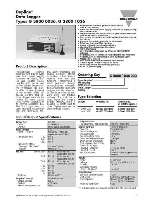
Product De s crip t ion• Programmable channel generator with optional built-in GSM Modem• Event and time based data logging functions for digital, analog and counter values• Log Records are sent to the central Dupline-Online Webserver via GSM Modem or the Internet• User access to real-time and historical Dupline-Online data via the Internet• Export of files with logged data via the internet • Real-time, timer and logic functions• Analog set-point control and monitoring • Light and Rollerblind control functions • Alarm Monitoring• User-friendly configuration via Windows 98/2000/NT/XP software• 2 x RS232 ports for configuration and Dupline data read/write • 1 x RS485 port for networking of up to 32 Data Loggers • Modbus-RTU protocol• Built-in software driver for external radio modem • 4 digital inputs / 4 digital outputs on-board • H8-housing for DIN-rail mounting (EN50022)• AC or DC power supplyProgrammable channel generator with built-in event and time based logging functions for digital, ana-log and counter values. Log Records can be sent to the central Dupline-On-line Webserver via built-in GSM modem (optional) or the Internet. Users can access real-time and his-torical logged data via the Internet as alarm buffers, trend curves, bargraphs or as comma separated files. The Data Logger also con-tains intelligent functions for light and roller blind con-trol, alarm monitoring andIn addition to that, there isrealtime, timer and logic functions. Programming isWindows-based configura-tion software. Up to 32 Data Loggers can be networked as slaves in a RS485 net-work using the Modbusprotocol. The unit has 4 digital inputs and 4 digitaloutputs onboard, and it is possible to create links to other Dupline networks via external Radio Modem.Input/Output Spe c i f i c a t ionsSupplyOrdering no. Ordering no.w. GSM telephone 115/230 VAC G 3800 0036 230 G 3800 1036 230 10-30 VDC G 3800 0036 800 G 3800 1036 800Type Selection Data LoggerTypes G 3800 0036, G 3800 1036Dupline ®G 3800 0036, G 3800 1036Ge ne ral Spe c i f i c a t ions Wiring DiagramsSupply Spe c i f i c a t ionsSupply Spe c i f i c a t ions (cont.)Power dissipation G3******* ≤ 6 W G3******* ≤ 7 WInrush current1 A Rated impulse withstand volt. 800 VDielectric voltageSupply - Dupline ® 500 V Supply - Output 200 VG 3800 0036, G 3800 1036 Mode of OperationLogging functions to Dup-line-OnlineThe G3800x036 Data Logger is a programmable channel gen-erator, which can perform event and time based logging func-tions. Digital signals changing state and analog signals cross-ing a set-point are recorded as events, while analog sig-nals and counter values are logged in regular user-defined time intervals. All Log Rec-ords include the address and description of the signal, and a time and date tag. Logged data are stored in non-volatile mem-ory and are simultaneously sent to the central Dupline-Online Webserver via GSM modem or the Internet. E ach Data Logger has its own unique ID-code that enables the central serv-er to uniquely identify where a log record is coming from and thereby save it at the correct position in the database.If Log Record transmission via the Internet is desired, an external pre-configured RS232-E thernet converter is required ( type E THCONV1).A Data Logger using Internet transmission will continue to re-transmit the Log Record every minute over a 24 hour period until an acknowledge from the central server is received. The data telegrams are encrypted to ensure safe transmission via the Internet.A Data Logger using GSM transmission will continue to re-send the Log Record as an SMS message until the GSM provider returns with an acknowledge that the SMS has been received. The cen-tral server is checking the telephone number of every received SMS data telegram to ensure safe transmission.Users can access real-time and historical logged data via the Internet as alarm buffers, trend curves, bargraphs or as comma separated files. Since data is stored in a central serv-er shared by multiple users with individual usernames and passwords allowing access to own data, there is no need to invest in new IT equipment. Any PC with an Internet connection and a standard browser can be used for data access. The cen-tral server is well-protected by a heavy-duty firewall and data back-up is performed on a daily basis to ensure data preserva-tion.Intelligent functionsThe Data Logger is alsoequipped with intelligent func-tions for lighting control, rollerblind control, temperaturecontrol and alarm monitoring.In addition to that the unit canbe configured to perform real-time, logic and timer functions.The windows based config-uration software is extremelyeasy to use due to the pre-pro-grammed functions.Data Logger configurationThe Data Logger is as defaultconfigured to operate as astandard channel generatorwithout logging and intelligentfunctions. In order to makeuse of the intelligent func-tions the Data Logger must beconfigured by means of theuser-friendly windows-basedconfiguration software. This isincluded in the package andmust be installed on a Win95/98/2000/NT/XP PC. Whenthe configuration is complet-ed the configuration is down-loaded into the Data Logger viaCOM1 (RS232 port). The con-figuration can be saved on a fileand it is also possible to uploadthe configuration from a DataLogger.In order to register the DataLogger for Dupline-Onlineoperation on the Internet, itis necessary to upload to theCentral Server a special config-uration file created by the con-figuration software.GSM Modem OptionThe G3******* Data Loggerhas a built-in GSM Modemwhich enables transmission ofevent and/or time based Logrecords to the Central servervia SMS messages. Alterna-tively, the GSM modem can beused for monitoring and con-trol of Dupline signals via SMSmessages to/from mobile GSMtelephones. There are 3 differentways to use SMS messaging:• The Data Logger can beprogrammed to send outevent based SMS messages.The event can be a channelswitching ON or OFF, orit can be an analog signalcrossing a setpoint.• Requests for status of digitalor analog data can be sentand answered via SMS mes-sages• Status of digital channelscan be controlled by sendingcommands via SMS messa-gesIn order to make use of theGSM modem, the following isrequired:• A SIM-card with the pin-code9090 needs to be insertedinto the slot in the front ofG3*******. The SIM-cardmust be a 3V type.• A GSM antenna needs tobe connected to the FMEconnector on G3*******.If the unit is installed in ametal enclosure, the antennamust be installed outside theenclosure and connectedto the Data Logger via a cable(an antenna of this type is avail-able as accessory).An L E D in the front ofG3******* indicates the statusof the GSM modem. By emit-ting different blink patterns, theL E D indicates “connecting”,“SIMcard missing”, “No net-work found”, “No responsefrom modem”, “SMS sent” and“SMS received”.RS232 portsThe Data Logger is equippedwith two RS232 ports (COM1and COM2) which both can beused by PC’s/PLC’s for read/write of Dupline data using theModbus-RTU protocol. COM1is also used for download andupload of configuration files(created by the Data Loggerconfiguration software) and forfirmware upgrades. If trans-mission of Log Records via theInternet is desired, the exter-nal RS232-E thernet converter(E THCONV1) needs to be con-nected to COM2. The sameis the case if the option for anexternal radio modem is desired.COM1 has a fixed baudrate of115 kBaud, while the baudrateof COM2 is adjustable.RS485 portThe RS485 port enables net-working of up to 32 Data Log-gers with or without automaticdata exchange. This enablescontrol and monitoring of upto 4096 data points. If desired,it is also possible to use Ether-net instead of RS485. In thatcase each Data Logger mustbe equipped with a convert-er. A Modbus Device Addressneeds to be assigned to eachData Logger during configur-ation. In a network with auto-matic data exchange, one DataLogger is configured as RS485Master, and will thus synchron-ize a continual automatic dataexchange between all the DataLoggers. When programmingthe individual Controllers it isthen possible to make refer-ences to signals in other Dup-line networks. For example thewind speed value measured bya sensor in one Dupline net-work, can be used in the rollerblind control function in theother Dupline networks.It is also possible to make e.g.“all lights OFF” functions fora big building by activating asingle pushbutton. A PC orPLC, connected to one of theCOM-ports of the G3800X036operating as RS485 Master,gets access to all 4096 datapoints using the Modbus proto-col. Also, using the PC makes itpossible to change the config-uration in any of the Data Log-gers in the network.In a network without automaticdata exchange, a PC or PLCneed to be RS485 Master andall the Data Loggers will oper-ate as Modbus-RTU slaves.This makes it possible for thePC or PLC to read/write datafrom any of the 32 Data Log-gers. See following RS485 net-working diagram for both oper-ating modes.Modbus-RTU protocolUsing the Modbus-RTU com-mands 2 and 3 through COM1,COM2 or RS485 makes itpossible to read any type ofDupline data (digital, analink,multiplexed analog or counterdata). The status of digital andmultiplexed analog data andreset of counter can be con-trolled via the commands 5, 6and 16. See manual for mem-ory map information.SoftwareThe Dupline Data Access soft-ware package (type no. DUP-DATACC) has been developedspecifically for the MasterGenerator and the Data Logger.It contains two software toolsthat provide easy access froma PC to Dupline digital, analogand counter data via one of theRS232 or RS485 ports. TheDDE-driver provides a Dynam-ic Data xchange interface,which can be used from appli-cations that support client sideDDE such as Microsoft EXCEL.Getting Dupline data into anEXCEL spreadsheet is a simplecopy-and-paste operation. TheDupline ActiveX driver providesan ActiveX interface, which isa Microsoft standard for com-G 3800 0036, G 3800 1036Dupline-Online Principal DiagramPin Assignment, COM1, COM2RS 232 Cable2 3 511 9 79-pin male to controller 15-pin female to radio modem5 916Pin Signal2 T x D3 R x D5 Signal Ground2352359-pin maleto controller9-pin femaleto PCmunication between two prod-ucts. The Dupline ActiveX driver can be used from any develop-ment tool that supports client side ActiveX such as Microsoft Visual Basic, Delphi and Bor-land C++ builder. The Dupline Data Access package can be used on single Data Loggers as well as Data Logger networks. Radio Modem driverThe Data Logger has a built-in driver for control of an external Radio Modem, which can be used to create wireless links where no cable is available in parts of an installation. OneData Logger just be defined asthe central Data Loggers andup to 32 Data Loggers can bedefined as remote Data Log-gers. The central Data Log-ger is continuously pollingand updating the Dupline datafrom all remote Data Loggersvia the radio modem network,and in this way it makes theentire system operate as onebig Dupline network. Apartfrom increased reaction time(depending on the numberof remote Data Loggers), thesystem will operate as if it wasone Data Logger connected toall the I/O-modules with cable.The Data Logger supportsthe Radio Modem type2ASxE and all 3AS types fromthe Finnish manufacturer SATEL(www.satel.fi). Find below anapplication diagram for theRadio Modem option.Note: Analink modules cannotbe used with Radio Modems.On-board I/OThe Data Logger has 4 digit-al inputs and 4 digital outputson-board. These have beenimplemented to reduce the costof remote stations with only afew signals (e.g. in connectionwith an SMS alarm system orradio modem remote stations).The onboard I/O’s are used viathe logic functions of the DataLogger, where they can beassigned to specific channeladdresses.Mode of Operation (cont.)Radio Modem ApplicationCentral MGENRemote MGEN #2Remote MGEN #1RS232AccessoriesRS232-Ethernet Converter ETHCONV1 (preconfigured)Dupline Data Access Software DUPDATACC GSM Antenna 900 MHz ANT11 x Data Logger G 3800 x036 xxx1 x User manual MAN G 3800 0036 ENG 1 x RS 232 cableRS 232-9 M/9 F 1 x Configuration softwareSW G 38xx36Scope of SupplyANT1RS232RS232G 3800 0036, G 3800 1036Dimensions (mm)。
Mornsun LS05-23BxxDR3 高功率 AC DC 转换器说明书

5W,DIY AC/DCconverterRoHSEN62368-1FEATURES●Ultra-wide 85-305VAC and 70-430VDC input voltage range ●Accepts AC or DC input (dual-use of same terminal)●Operating ambient temperature range:-40℃to +85℃●High I/O isolation test voltage up to 4000VAC●Multi application,compact size,flexible layout ●No-load power consumption 0.1W●Output short circuit,over-current protection ●Plastic case meets UL94V-0flammability ●Pollution level Ⅲ(meet IEC62368-1)LS05-23BxxDR3series is one of Mornsun’s miniaturized potting highly efficient green power AC-DC Converters.They feature wide input range accepting either AC or DC voltage,high reliability,low power consumption,reinforced isolation and strong applicability.All models are particularly suitable for industrial control,electric power,instrumentation and smart home applications which have high requirement for dimension and don’t have high requirement on EMC.For extremely harsh EMC environment,we recommend using the application circuit show in Design Reference of this datasheet.Input SpecificationsItemOperating Conditions Min.Typ.Max.Unit Input Voltage Range AC input 85--305V AC DC input70--430VDC Input Frequency 47--63HzInput Current 115V AC ----0.2A 230V AC ----0.1Inrush Current115V AC --20--230V AC--40--Recommended External Input Fuse 1A,slow-blow,required(The actual use needs to be selected according to the application enviroment)Hot PlugUnavailableOutput SpecificationsItemOperating Conditions Min.Typ.Max.UnitOutput Voltage Accuracy 10%-100%load --±5--%Line Regulation Rated load --±1.5--Load Regulation 10%-100%load--±3--Ripple &Noise *20MHz bandwidth (peak-to-peak value),10%-100%load--80150mV Temperature Coefficient --±0.15--%/°C Stand-by Power Consumption230V AC--0.100.15W Selection GuideCertificationPart No.Output PowerNominal Output Voltage and Current (Vo/Io)Efficiency at 230V AC(%)Typ.Capacitive Load(uF)Max.ENLS05-23B03DR3 3.3W3.3V/1000mA 682200LS05-23B05DR35W 5V/1000mA 711500LS05-23B09DR39V/560mA 74680LS05-23B12DR312V/420mA 75470LS05-23B15DR315V/340mA 77330LS05-23B24DR324V/210mA77100Note:The nominal output voltage refers to the voltage applied to the load terminal after adding external circuits.Short Circuit Protection Hiccup,continuous,self-recovery Over-current Protection≥110%Io,self-recovery Minimum Load10----%Hold-up Time 115V AC input--8--ms 230V AC input--40--Note:1.*The“parallel cable”method is used for ripple and noise test,please refer to AC-DC Converter Application Notes for specific information;2.The product is able to work with0%-10%load and with stable output.General SpecificationsItem Operating Conditions Min.Typ.Max.UnitIsolation Input-output Electric Strength Test for1min.,leakage current<5mA4000----VACInsulation Resistance Input-output At500VDC100----MΩOperating Temperature-40--+85℃Storage Temperature-40--+105Storage Humidity----95%RHPower Derating +55℃to+85℃ 1.67----%/℃85V AC-100VAC 1.33----%/V AC 277V AC-305V AC0.72----Safety Standard Design refer to IEC/UL62368-1,IEC/EN60335-1, IEC/EN61558-1&EN62368-1(Report)Safety Class CLASS IIMTBF MIL-HDBK-217F@25°C>1,000,000h Mechanical SpecificationsCase Material Black plastic,flame-retardant and heat-resistant(UL94V-0)Dimension27.60x18.50x7.80mmWeight7.5g(Typ.)Cooling method Free air convectionElectromagnetic Compatibility(EMC)Emissions CECISPR32/EN55032CLASS A(Application circuit1,4)CISPR32/EN55032CLASS B(Application circuit2,3,5) RECISPR32/EN55032CLASS A(Application circuit1,4)CISPR32/EN55032CLASS B(Application circuit2,3,5)Immunity ESD IEC/EN61000-4-2Contact±6KV/Air±8KV Perf.Criteria B RS IEC/EN61000-4-310V/m perf.Criteria AEFTIEC/EN61000-4-4±2KV(Application circuit1,2)perf.Criteria BIEC/EN61000-4-4±4KV(Application circuit3,4,5)perf.Criteria BSurgeIEC/EN61000-4-5line to line±1KV(Application circuit1,2)perf.Criteria BIEC/EN61000-4-5line to line±2KV(Application circuit3,4)perf.Criteria BIEC/EN61000-4-5line to line±2KV/line to ground±4KV(Application circuit5)perf.Criteria BCS IEC/EN61000-4-610Vr.m.s perf.Criteria A Voltage dip,shortinterruption and voltagevariationIEC/EN61000-4-110%,70%perf.Criteria AProduct Characteristic CurveNote:①With an AC input between85-100VAC/277-305VAC and a DC input between70-120VDC/390-430VDC,the output power must be derated as per temperature derating curves;②This product is suitable for applications using natural air cooling;for applications in closed environment please consult factory oroneof our FAE. Additional Circuits Design ReferenceLS series additional circuits design referenceLS05series additional components selection guide(No EMC devices)Part No.C1(required)C2(required)L1(required)C3(required)C4CY1(required)TVSLS05-23B03DR310uF/450V(-25℃to+85℃,85-305VAC input;-40℃to+85℃,165-305VAC input)22uF/450V(-40℃to+85℃,85-305VAC input)820uF/6.3V(solid-state capacitor) 2.2uH/36mΩ/3.3A220uF/16V0.1uF/50V1.0nF/400V ACSMBJ7.0ALS05-23B05DR3470uF/16V(solid-state capacitor)LS05-23B09DR347uF/35V SMBJ12ALS05-23B12DR3270uF/16V(solid-state capacitor)4.7uH/60mΩ/2.2A SMBJ20ALS05-23B15DR3220uF/25V(solid-state capacitor)LS05-23B24DR3220uF/35V SMBJ30A Note:1.C1is used as filter capacitor with AC input(must be connected externally)and as EMC filter capacitor with DC input(must be connected),and it is recommended to use the capacitor with ripple current>200mA@100KHz.2.We recommend using an electrolytic capacitor with high frequency and low ESR(ESR of C3at low temperature of-40℃≤1.1Ω)rating for C3(refer to manufacture’s datasheet),electrolytic capacitor can be used for C2when applied in normal and high temperature bined with C2,L1,they form a pi-type filter circuit.Choose a capacitor voltage rating with at least20%margin,in other words not exceeding80%.C4is a ceramic capacitor,used for filtering high frequency noise.3.A suppressor diode(TVS)is recommended to protect the application in case of converter failure and specification should be1.2times of the output voltage.Environmental Application EMC SolutionLS series environmental application EMC solution selection tableRecommendedcircuitApplicationenvironmental Typical industryInput voltagerangeEnvironmenttemperature Emissions Immunity1Basic application None85-305V AC -40℃to+85℃CLASS A CLASSⅢ2Indoor civilenvironmentSmart home/Home appliances(2Y)-25℃to+55℃CLASS B CLASSⅢIndoor generalenvironmentIntelligent building/Intelligentagriculture3Indoor industrialenvironment Manufacturing workshop-25℃to+55℃CLASS B CLASSⅣ4Outdoor generalenvironmentITS/Video monitoring/Chargingpoint/Communication/Securityand protection-40℃to+85℃CLASS A CLASSⅣ5OutdoorindustrialenvironmentElectricity/Grid-40℃to+85℃Class B CLASSⅣElectromagnetic Compatibility Solution--Recommended Circuit1.Application circuit1——Basic applicationApplication circuit1Application environmental Ambient temperature range Immunity CLASS Emissions CLASS Basic application-40℃to+85℃CLASSⅢCLASS AFUSE1A/300V,slow-blow,requiredR124Ω/3W(wire-wound resistor,required)LDM 4.7mH/Max:15Ω/Min:0.2A Note:R1is the input plug-in resistor,this resistor needs to be a wire-wound resistor(required),please do not select chip resistor or carbon film resistor. 2.Application circuit2——Universal system recommended circuits for indoor civil/general environmentApplication circuit2Application environmental Ambient temperature range Immunity CLASS Emissions CLASS Indoor civil/general-25℃to+55℃CLASSⅢCLASS BComponent Recommended valueR124Ω/3W(wire-wound resistor,required)LDM 4.7mH/Max:15Ω/Min:0.2ACX0.1uF/310VACFUSE1A/300V,slow-blow,required Note1:In the home appliance application environment,the two Y capacitors of the primary and secondary need to be externally connected (CY1/CY2,value at2.2nF/250VAC),which can meet the EN60335certification.Note2:According to the certification requirements,the X capacitor needs to be connected in parallel with the bleeder resistance,the recommended resistance value is less than3.8MΩ,and the actual need to be selected according to the certification standard.Note3:R1is the input plug-in resistor,this resistor needs to be a wire-wound resistor(required),please do not select chip resistor or carbon film resistor. 3.Application circuit3——Universal system recommended circuits for indoor industrial environmentApplication circuit3Application environmental Ambient temperature range Immunity CLASS Emissions CLASSIndoor industrial-25℃to+55℃CLASSⅣCLASS BComponent Recommended valueMOV S14K350CX0.1uF/310V ACLDM 4.7mH/Max:15Ω/Min:0.2AR133Ω/3W(wire-wound resistor,required)FUSE2A/300V,slow-blow,required Note1:According to the certification requirements,the X capacitor needs to be connected in parallel with the bleeder resistance,the recommended resistance value is less than3.8MΩ,and the actual need to be selected according to the certification standard.Note2:R1is the input plug-in resistor,this resistor needs to be a wire-wound resistor(required),please do not select chip resistor or carbon film resistor. 4.Application circuit4——Universal system recommended circuits for outdoor general environmentApplication circuit4Application environmental Ambient temperature range Immunity CLASS Emissions CLASSOutdoor general environment-40℃to+85℃CLASSⅣCLASS AComponent Recommended valueMOV S14K350LDM 4.7mH/Max:15Ω/Min:0.2AR133Ω/3W(wire-wound resistor,required)FUSE2A/300V,slow-blow,required Note:R1is the input plug-in resistor,this resistor needs to be a wire-wound resistor(required),please do not select chip resistor or carbon film resistor.5.Application circuit5——Universal system recommended circuits for outdoor industrial environmentApplication circuit5Application environmental Ambient temperature range Immunity CLASS Emissions CLASSOutdoor industrial environment-40℃to+85℃CLASSⅣCLASS BComponent Recommended valueC122uF/450VMOV S14K350CX0.1uF/310V ACLDM330uH/960mΩMax/0.31ALCM 3.1mHR147Ω/5W(wire-wound resistor,required)CY3/CY41nF/400V ACFUSE2A/300V,slow-blow,required Note1:According to the certification requirements,the X capacitor needs to be connected in parallel with the bleeder resistance,the recommended resistance value is less than3.8MΩ,and the actual need to be selected according to the certification standard.Note2:R1is the input plug-in resistor,this resistor needs to be a wire-wound resistor(required),please do not select chip resistor or carbon film resistor.6.For additional information please refer to application notes on . Dimensions and Recommended LayoutLS05-23BxxDR3series dimensionsLS05-23BxxDR3series recommended padNote:There is a slot(non-metallic hole)between pin4/5.For details,please refer to the recommended dimensions or pad.Note:1.For additional information on Product Packaging please refer to .Packaging bag number:58220074;2.External electrolytic capacitors are required to modules,more details refer to typical applications;3.This series is a potting product,at least6.4mm creepage distance between the primary and secondary external components of themodule is needed to meet the safety requirement,refer to the recommended welding hole design in the external dimension drawing;4.Unless otherwise specified,parameters in this datasheet were measured under the conditions of Ta=25℃,humidity<75%,nominal inputvoltage(115V and230V)and rated output load;5.All index testing methods in this datasheet are based on our company corporate standards;6.We can provide product customization service,please contact our technicians directly for specific information;7.Products are related to laws and regulations:see"Features"and"EMC";8.Our products shall be classified according to ISO14001and related environmental laws and regulations,and shall be handled byqualified units.Mornsun Guangzhou Science&Technology Co.,Ltd.Address:No.5,Kehui St.1,Kehui Development Center,Science Ave.,Guangzhou Science City,Huangpu District,Guangzhou,P.R.China Tel:86-20-38601850Fax:86-20-38601272E-mail:***************。
ABB B21、B23 和 B24 能量计说明书

DEUTSCHABB-B21-, B23- und B24-EnergiezählerRev 01 - 12/2022Diese Handbuch ist auch im HTML5-Format verfügbar.Inhaltsverzeichnis1. ABB-B21-, B23- und B24-Energiezähler (1)1.1. Eigenschaften und Voraussetzungen (1)1.2. Installation und Konfiguration (2)1.2.1. Verkabelung der RS485-zu-USB-Schnittstelle (2)1.2.2. Konfiguration des ABB-Zählers für Venus OS (2)1.2.3. GX-Gerätekonfiguration (3)1.1. Eigenschaften und VoraussetzungenVenus OS unterstützt die Energiezähler der B-Serie von ABB B21, B23 und B24 als Alternative zu den Energiezählern von Carlo Gavazzi. Diese Zähler können als allgemeiner Wechselstromzähler oder zur Messung von Leistung und Energie für einen nicht unterstützten PV-Wechselrichter oder ein Aggregat verwendet werden. Die folgenden Produktkennungen von ABB werden unterstützt:•B21: Einphasiger Zähler, bis zu 65 A, 35 mm breit. Produktkennung 2CMA100155R1000 SilverVerwenden Sie den B21 Silver als Ersatz für die ET112.•B23: Dreiphasiger Zähler, interner Shunt, bis zu 65 A pro Phase, 70 mm breit. Produktkennung 2CMA100169R1000 Silver Verwenden Sie den B23 Silver als Netzzählerersatz für den EM24 in ESS-Systemen oder zur Messung eines dreiphasigen PV-Wechselrichters.•B24: Dreiphasiger Zähler, verwendet Stromwandler. 70 mm breit. Übersetzungsverhältnis konfigurierbar, bis zu 1000 A pro Phase. Die Stromwandler müssen separat erworben werden. Eine Auswahlanleitung für Stromwandler finden Sie auf Seite 10 des verlinkten Dokuments von ABB. Produktkennung 2CMA100183R1000 SilverVerwenden Sie den B24 Silver als Ersatz für den EM24 in ESS-Systemen mit mehr als 65 A pro Phase.Eine allgemeine Übersicht über die Funktionen finden Sie hier (klicken Sie auf Funktionen): ABB-Energieeffizienzgeräte. Detaillierte Informationen zu dem jeweiligen Zähler erhalten Sie über die oben angegebenen Produktkennungen.Beachten Sie, dass die …Steel“-Versionen nicht unterstützt werden, da sie keine Messung der umgekehrten Energie erlauben, sodass es unmöglich ist, die verkaufte Energie anzuzeigen. Diagramme und Zähler auf VRM werden mit einem Steel-Meter nicht korrekt angezeigt. Vergewissern Sie sich, dass der gewünschte Zähler die Bezeichnung Silver (oder besser) trägt und über Modbus RS485 verfügt.Mindestversion der Venus OS-Firmware: 2.92 oder neuer.Piggybacking (Netz auf L1 und PV-Wechselrichter auf L2) wird nicht unterstützt.Jedes dieser Modelle verfügt über einen LCD-Bildschirm und wird über eine RS485-zu-USB-Schnittstelle mit dem GX-Gerät verbunden. Es wird kein Zigbee-Anschluss unterstützt.Die dreiphasigen Zähler verwenden die Vektormethode für die Berechnung der Gesamtleistung. Dies ist in vielen Ländern wie Deutschland und Österreich die bevorzugte Methode. Die Gesamtleistung wird separat in die importierten und exportierten Energiewerte integriert, anstatt nur die einzelnen Phasenwerte zu summieren.Im Gegensatz zum CG-Zähler wird der ABB-Zähler über die Geräteliste und nicht über Einstellungen > Energiezähler desGX-Geräts konfiguriert. Siehe das Kapitel GX-Gerätekonfiguration [3].1.2. Installation und Konfiguration1.2.1. Verkabelung der RS485-zu-USB-SchnittstelleSie benötigen einen sehr kleinen Schlitzschraubendreher, um an die Schrauben des RS485-Anschlusses an den Klemmen der B-Serie zu gelangen.1.2.2. Konfiguration des ABB-Zählers für Venus OSEs müssen einige Einstellungen wie die Baudrate und die richtige Parität vorgenommen werden. Die folgenden Schritte sind notwendig, um den ABB-Zähler für Venus zu konfigurieren:1.Öffnen Sie die vordere Kunststoffabdeckung. Bei geschlossener Abdeckung können Sie die SET-Taste nicht betätigen.2.Drücken Sie die SET-Taste. Auf der LCD-Anzeige wird …RS-485“ angezeigt.3.Drücken Sie auf OK. Auf der LCD-Anzeige wird …Prot“ (Protokoll) angezeigt.4.Drücken Sie die Abwärtstaste. Auf der LCD-Anzeige wird …baud“ angezeigt. Betätigen Sie dann OK.5.Die aktuelle Baudrate wird auf dem Bildschirm angezeigt. Betätigen Sie die Taste SET. Der Bildschirm beginnt zu blinken.6.Drücken Sie den Pfeil nach unten, bis …38400“ angezeigt wird. Betätigen Sie dann OK.7.Halten Sie die Taste OK eine Sekunde lang gedrückt, um zum vorherigen Menü zurückzukehren. Es wird wieder …baud“angezeigt.8.Betätigen Sie den Pfeil nach unten, bis …Parity“ (Parität) angezeigt wird. Betätigen Sie OK. Die aktuelle Einstellung wirdangezeigt (Werkseinstellung …even“ [gerade]).9.Betätigen Sie die Taste SET. Das Display blinkt.10.Betätigen Sie die Abwärtstaste, bis …None“ (Keine) angezeigt wird. Betätigen Sie OK.11.Betätigen Sie mehrmals für eine Sekunde die Taste OK, um das Menü vollständig zu verlassen und zum Hauptbildschirmzurückzukehren.12.Schließen Sie die Abdeckung.Ausführliche Informationen zur Installation und Konfiguration finden Sie in der ABB-Dokumentation, die unter Eigenschaften und Anforderungen [1] verlinkt ist.1.2.3. GX-GerätekonfigurationNach dem ordnungsgemäßen Anschluss und dem Einschalten werden die Zähler auf dem GX-Gerät in der Geräteliste angezeigt. Beachten Sie, dass im Gegensatz zu anderen Energiezählern die aktuellen Werte des ABB-Zählers immer als positive Zahlen angezeigt werden. Das ist normal.Blättern Sie nach unten zur Registerkarte Setup (Einstellung) und legen Sie die Funktion des Energiezählers fest:Sobald die Funktion richtig eingestellt ist, ist die Konfiguration abgeschlossen.。
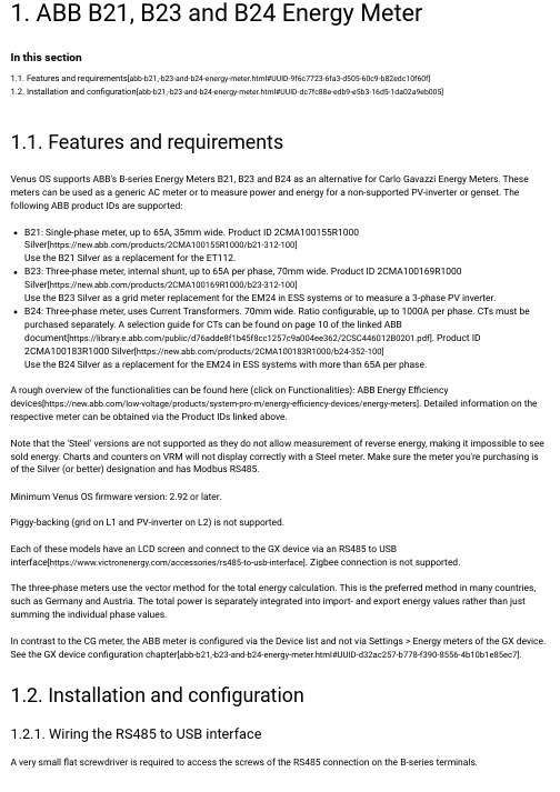
ABB B21、B23和B24能源表说明书
1. ABB B21, B23 and B24 Energy MeterIn this section1.1. Features and requirements [abb-b21,-b23-and-b24-energy-meter.html#UUID-9f6c7723-6fa3-d505-60c9-b82edc10f60f]1.2. Installation and configuration [abb-b21,-b23-and-b24-energy-meter.html#UUID-dc7fc88e-edb9-e5b3-16d5-1da02a9eb005]1.1. Features and requirementsVenus OS supports ABB's B-series Energy Meters B21, B23 and B24 as an alternative for Carlo Gavazzi Energy Meters. These meters can be used as a generic AC meter or to measure power and energy for a non-supported PV-inverter or genset. The following ABB product IDs are supported:A rough overview of the functionalities can be found here (click on Functionalities): ABB Energy Efficiencydevices [https:///low-voltage/products/system-pro-m/energy-efficiency-devices/energy-meters]. Detailed information on the respective meter can be obtained via the Product IDs linked above.Note that the 'Steel' versions are not supported as they do not allow measurement of reverse energy, making it impossible to see sold energy. Charts and counters on VRM will not display correctly with a Steel meter. Make sure the meter you're purchasing is of the Silver (or better) designation and has Modbus RS485.Minimum Venus OS firmware version: 2.92 or later.Piggy-backing (grid on L1 and PV-inverter on L2) is not supported.Each of these models have an LCD screen and connect to the GX device via an RS485 to USBinterface [https:///accessories/rs485-to-usb-interface]. Zigbee connection is not supported.The three-phase meters use the vector method for the total energy calculation. This is the preferred method in many countries,such as Germany and Austria. The total power is separately integrated into import- and export energy values rather than just summing the individual phase values.In contrast to the CG meter, the ABB meter is configured via the Device list and not via Settings > Energy meters of the GX device.See the GX device configuration chapter [abb-b21,-b23-and-b24-energy-meter.html#UUID-d32ac257-b778-f390-8556-4b10b1e85ec7].1.2. Installation and configuration1.2.1. Wiring the RS485 to USB interface A very small flat screwdriver is required to access the screws of the RS485 connection on the B-series terminals.B21: Single-phase meter, up to 65A, 35mm wide. Product ID 2CMA100155R1000Silver [https:///products/2CMA100155R1000/b21-312-100]Use the B21 Silver as a replacement for the ET112.B23: Three-phase meter, internal shunt, up to 65A per phase, 70mm wide. Product ID 2CMA100169R1000Silver [https:///products/2CMA100169R1000/b23-312-100]Use the B23 Silver as a grid meter replacement for the EM24 in ESS systems or to measure a 3-phase PV inverter.B24: Three-phase meter, uses Current Transformers. 70mm wide. Ratio configurable, up to 1000A per phase. CTs must be purchased separately. A selection guide for CTs can be found on page 10 of the linked ABBdocument [https:///public/d76adde8f1b45f8cc1257c9a004ee362/2CSC446012B0201.pdf]. Product ID2CMA100183R1000 Silver [https:///products/2CMA100183R1000/b24-352-100]Use the B24 Silver as a replacement for the EM24 in ESS systems with more than 65A per phase.RS485 to USBRS485 signal ABB B-series terminal BlackGND terminal C (35)OrangeData +terminal B (36)Yellow Data -terminal A (37)Note that the red, green and brown wire coming out of the RS485 to USB cable are not used.1.2.2. Configuration of the ABB meter for Venus OSA few settings such as baud rate and the correct parity must be made. The following steps are necessary to configure the ABB meter for Venus:For detailed installation and configuration information, see the ABB documentation linked under Features and requirements [abb-b21,-b23-and-b24-energy-meter.html#UUID-9f6c7723-6fa3-d505-60c9-b82edc10f60f].1.2.3. GX device configurationAfter proper connection and powering up, the meter(s) will be visible on the GX device in the Device list.Note that unlike other energy meters, the current values of the ABB meter are always displayed as positive numbers. This is normal.Scroll down to the Setup tab and set the Role of the Energy Meter:1. Open the front plastic cover. With the cover closed you cannot push the SET button.2. Push the SET button. The LCD will display "RS-485".3. Push OK. The LCD will show "Prot" (protocol).4. Push the down button. LCD will show "baud". Then press OK.5. The current baud rate will be shown on the screen. Press SET. The screen will start to blink.6. Press the down-arrow until "38400" is shown. Then press OK.7. Press and hold OK for a second to return to the previous menu. It will show "baud" again.8. Press the down arrow until "Parity" is displayed. Press OK. The current setting will be displayed (factory default "even").9. Press SET. The display will blink.10. Press the down button until "None" is displayed. Press OK.11. Press and hold OK for a second a number of times to back out of the menu completely back to the main screen.12. Close the cover.Once the Role has been properly set, the configuration is done. Prev[index-en.html]© 2022 Victron Energy。
太阳能控制器使用说明
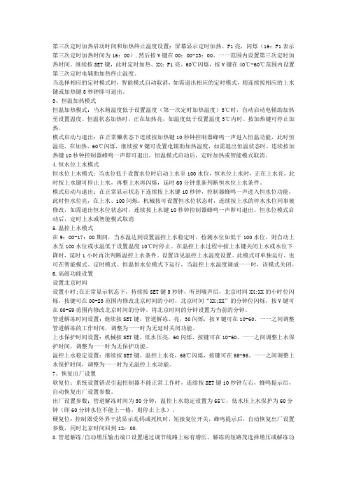
第三次定时加热启动时间和加热终止温度设置:屏幕显示定时加热、F1亮,闪烁(16:F1表示第三次定时加热时间为16:00).然后按V键在00:00-23:00、一一范围内设置第三次定时加热时间。
继续按SET键,此时定时加热、XX:F1亮。
60℃闪烁,按V键在40℃-60℃范围内设置第三次定时电辅助加热终止温度。
当选择相应的定时模式时,智能模式自动取消,如需退出相应的定时模式,则连续按相应的上水键或加热键3秒钟即可退出。
3、恒温加热模式恒温加热模式:当水箱温度低于设置温度(第一次定时加热温度)3℃时,自动启动电辅助加热至设置温度。
恒温状态加热时,正在加热亮,如温度低于设置温度3℃内时。
按加热键可停止加热。
模式启动与退出:在正常懒状态下连续按加热键10秒钟控制器蜂鸣一声进入恒温功能,此时恒温亮,在加热、60℃闪烁,继续按V键可设置电辅助加热温度,如需退出恒温状态时,连续按加热键10秒钟控制器蜂鸣一声即可退出,恒温模式启动后,定时加热或智能模式取消。
4.恒水位上水模式恒水位上水模式:当水位低于设置水位时启动上水至100水位,恒水位上水时,正在上水亮,此时按上水键可停止上水,再整上水再闪烁,延时60分钟重新判断恒水位上水条件。
模式启动与退出:在正常显示状态下连续按上水键10秒钟,控制器蜂鸣一声进入恒水位功能,此时恒水位亮,在上水、100闪烁,机械按可设置恒水位状态时,连续按上水的停水水位同事被修改,如需退出恒水位状态时,连续按上水键10秒钟控制器蜂鸣一声即可退出。
恒水位模式启动后,定时上水或智能模式取消5.温控上水模式在9:00-17:00期间,当水温达到设置温控上水稳定时,检测水位如低于100水位,则自动上水至100水位或水温低于设置温度10℃时停止。
在温控上水过程中按上水键关闭上水或水位下降时,延时1小时再次判断温控上水条件。
设置详见温控上水温度设置。
此模式可单独运行,也可在智能模式、定时模式、恒温恒水位模式下运行,当温控上水温度调成一一时,该模式关闭。
- 1、下载文档前请自行甄别文档内容的完整性,平台不提供额外的编辑、内容补充、找答案等附加服务。
- 2、"仅部分预览"的文档,不可在线预览部分如存在完整性等问题,可反馈申请退款(可完整预览的文档不适用该条件!)。
- 3、如文档侵犯您的权益,请联系客服反馈,我们会尽快为您处理(人工客服工作时间:9:00-18:30)。
BE23控制器操作说明
西宁雅图机电有限公司
一.概述:
BE23自动启动控制器是具备发电机组自动启动开关功能。
带有发动机组保护系统同时提供重要的发电机组资料。
如:电流、电压、频率、功率、发动机水温及油压等参数。
使用按建市选择开关,可外加锁匙开关。
BE23可以通过板面调校或使用附加模块以电脑来控制及显示资料。
BE23模块可监测三相或单相电压、频率及发电机的单项电流。
也显示伏安、功率与无功。
这些参数可通过面板上的发光二极管来显示。
用户可以自行编定多个输入输出来适应各种常开、常闭信号、开关及延时。
BE23通过其RS232接口可以与电脑连接实现远程监控。
二、控制器面板结构的介绍
二极管数码显示窗口。
此窗口可以显示各项参数及各种故障
报警。
技术人员可通过此窗口进行各项参数社定及编程
通过按“左键”和“右键”两键可以浏览各项菜单的详细内容。
可选择的菜单。
通过按“上键”和“下键”可选择其中的一个菜单。
选中的菜单对应的指示灯会亮。
二极管数码显示窗口会显示相应的内
容。
(详细说明见后)
Alarm (报警菜单)Program(编程菜单)
Power (功率菜单)V/A/Hz/h(电压/电流/频率/累计时间)
Engine (发动机菜单)
灯(红色)显示故障报警。
OIL --- 机油压力低报警/停机
TEMPERATURE ---发动机温度高报警/停机
- 蓄电池电压过高或过低报警FUEL----燃油油位过低报警/停机
- 紧急停车报警(或自动状态时按停车键) SPEED---超速报警/停车
AUTO/MAN (自动/手动模式)通过按此键可以选择自动或手动操作模式.
按下此键时,如AUTO上方的绿灯亮,表示控制器已经处于自动状态。
再
次按下此键绿灯熄灭表示控制器已经处于手动操作状态。
在手动模式状态下
可通过START(起动)和STOP(停止)键来操作机组。
START/ON(手动起动/启动控制器)
ON (启动控制器) 控制器在关断(通过OFF关闭模块但直流总电源是接通的)
状态下,通过按此键可以打开控制器进入操作状态. START(启动机组)控制器在手动操作模式时通过此键可以手动启动机组.
STOP/OFF (手动停机/关闭控制器-报警复位)
OFF(关闭控制器) 控制器在操作状态下,通过按此键可以关闭控制器进入休
眠状态.同时在二极管数码显示窗口左下脚有一个红亮点显
示.机组出现报警后在停机状态可通过此键对报警复位.
STOP(停止机组)控制器在手动操作模式时通过此键可以手动停止机组.
ACK(报警消音) 机组出现故障报警时,通过此键可对报警声进行消音.
此键也是设置参数的功能键
三、菜单功能的介绍
Alarm(报警菜单): 故障报警出现后一是通过二极管数码显示窗口显示报警内容同时
报警菜单红色指示等闪烁,二是直接通过面板上的六个故障报警
显示(出现报警时对应的红色指示灯变亮)。
[Hi I] 过流报警停机[Hi P]过载报警停机
[Lo Pr]机油压力低报警停机 [F Pr] 低油压力传感器失灵报警
[Hi ℃]发动机温度高报警停机[F ℃]温度传感器失灵报警
[Hi Fr] 高频率报警停机 [Lo Fr]频率过低报警停机
[F AL] 充电发电机故障报警停车[bELt] 皮带断裂报警停车
[F Pi] 转速传感器故障报警 [F Cr] 起动失败报警停车
[Lo U]机组低电压报警停车[Hi U] 机组高电压报警停车
[Lo SP]低转速报警停车[FUEL] 低燃油位报警
[In 4] 辅助报警输入点4输入报警停车
注:自动状态下,所有保护均起作用;手动状态下,除低频率和低电压外其它保护均起作用。
Program(编程菜单)通过此菜单可对控制器进行各项参数设定。
这项工作是由技术工程师来完成的。
Power(功率菜单)通过此菜单可以观察机组的功率及功率因数。
[U A]—视在功率[Act.P]—有功功率
[UA r]—无功功率[P F]—功率因数
V/A/Hz/h(电压/电流/频率/累计时间)通过此菜单可以观察机组的三相电压,一相电流,机组频率,机组的累计运行时间。
通过“左键”和“右键”选定各项[U Ac]—三相电压显示;显示窗口左端有一光标上下移动,光标在上端表示
L1相电压,光标在中间表示L2相电压,光标在下端表示L3相电压。
[Curr]—一相电流
[FrEq]--- 显示机组的频率
[Hour]--- 机组的累计运行时间
注:在此菜单下任意时候按ACK(消音键),数码显示窗口就会显示参数名称。
Engine(发动机菜单)通过此菜单科观察发动机的信息和各项测量数据。
[t.On]----发电机组起动延时时间(AMF 输入2)
[t.OFF]----发电机组停车延时时间(AMF 输入2)
[COOL]---发电机组冷却延时停车时间.
[StOP]---- 关闭停车电磁阀的延时时间
[HEAt]----机组预热时间
[TgEn]----带载前机组预热时间
[StA]-----正在启动机组
[LOAD]----输出负荷开关已经闭合,机组带载.
[----]-----BE23正在等待执行命令.
[r PM]----发动机的转速显示值.
[OIL]-----机油压力显示值
[tEmP]-----发动机的温度显示值
[bAtt]-----蓄电池的电压值显示
(任意时候按ACK<消音键>,数码显示窗口就会显示此参数)
[FUEL]----燃油箱内燃油位置(以百分数显示)
注:发动机菜单前的黄色灯在机组运行时也作为发动机运行指示灯.
四、控制器接线原理图及外观。
