DP使用手册-一体化定位器补充说明
DP-20系列智能监控装置使用手册ver1.3

1
DP-20 系列综合智能监控装置
使用手册
2. 装置简介
DP-20 系列智能监控装置是许继测控仪表有限公司自主研发生产,实现对 35kV 及以下 配电等级的馈线、厂用变、电动机、电容器及 PT 柜等的保护与测控;可分散安装于高压开 关柜上,也可集中组屏。
2.2. 装置主要功能
针对被保护设备及保护要求的不同,装置可配置不同的功能,产品功能配置如下表: 产品型号 产品功能 两段过流保护 (速断) 过流反时限保护 过负荷保护 低电压保护 控制回路断线 PT 断线监视 保 护 功 能 弹簧未储能报警 零序保护 母线绝缘监察 三相一次重合闸 后加速保护 低频减载 过电压保护 两段负序保护(定时 限和反时限) 高压侧零序三段过流 保护 线路 DPL-21 ■ ■ ■ ■ ■ ■ ■ ■ ■ ■ ■ ■ ■ ■ ■ ■ ■ ■ ■ ■ 配电变 DPT-21 ■ ■ ■ ■ ■ ■ ■ 电动机 DPM-21 ■ ■ ■ ■ ■ ■ ■ ■ ■ 电容器 DPC-21 ■ ■ ■ ■ ■ ■ ■ ■ ■ ■ ■ ■ ■ ■ 绝缘监察 DPV-21 PT 并列 DPV-22
低压侧零序三段过流保护轻瓦斯告警重瓦斯跳闸超温跳闸告警过热保护电机启动保护堵转保护不平衡电压保护不平衡电流保护闭锁投切压力异常告警pt并列遥测电压测量三相电压频率负序电压电压31次谐波测量监测i段ii段母线电压监测i段ii段母线电压零序电压电流测量三相电流负序电流电流31次谐波测量零序电流高压侧有功无功视在功率四象限电能低压侧零序电流不平衡电压不平衡电流故障录波soe事件记录1000条di开关量输入12di12di12di12di12di12dido无操作回路do6do6do6do6do6do4路备用2路告警6do带操作回路的do输出2do2do3do2do通讯一路rs485接口一路can或者一路rs485接口选配选配选配选配选配选配dp20系列综合智能监控装置使用手册44开关量输出do输出模式有电平与脉冲两种客户使用时可根据需求通过软件自己设置电平为持续保持信号脉冲信号保持时间为10s3
DP100说明书V1 JIATEN数显箱操作说明书

为了确保仪器正确安全的使用,在其出版的手册中使用了不同的安用户手册使用约定安全标志全标志(警告示语和安全警示标志),以便用于识别,防止危险并避免事故。
一般警示标志:表示存在潜在的危险,如果不注意,可能会造成轻度或中度的人身伤害或财产损失。
特殊警令标志:禁止特定的行动,左侧表示“禁止拆卸”。
特殊声明:本用户说明手册仅供用户参考,如果说明书中的说明文字与实物的操作方式存 在差异时,以实物的操作方式为准!本公司保留对该产品进行性能升级的权力,当公司对产品 进行升级时,恕不另行通知!。
DP100的所有解释权归嘉腾仪器仪表有限公司所有!注释类型本手册中使用下列类型的注释,帮助操作人员通过正确的使用仪器,获得可靠的测量数据。
重要● 一种重要的注释,是完成一项任务所必需的知识,如想顺利完成任务,不能忽 视这项注释。
● 一种提示您小心的注释,如不注意可能会造成数据丢失,降低精度,产生故障 或无法正常使用。
注意●这种注释是强调或补充主要文字内容的重要,它也是提供一些特殊的信息(例如存储器限制设备配置或特殊版本的软件说明)。
提示●提示是一种能帮助用户的注释,它根据用户的需求来帮助用户使用好本文所描述的技术和程序。
●它也提供了与论述主题相关的参考信息。
使用环境条件●避免暴露于烈日或高温下,使用温度必须在0~40 o C的范围内。
●远离高电压,大电流,强磁场的设备。
●光学尺信号电缆线尽量远离电源线。
●避免使用在铁屑,油,水,粉尘环境及安装在的振动较大的环境。
●远离强酸,强碱及化学药品。
使用说明● 如果发生故障,例如在电源开启的情况下,液晶显示屏无图像显示,应停止使用DP100 数显箱。
同时通知嘉腾仪器仪表公司立即派人修理。
在这种情况下,如果继续使用DP100 数显箱,将可能导致电击或火灾。
● 不要让异物,如水、金属或其它液体从后面的接口处进入DP100 数显箱,否则将可能导致电击或火灾。
● 不要损坏或改装AC电源适配器的电源线。
DPGrid使用手册

DPGrid操作手册第一章DPGrid系统目录结构1.1 系统目录DPGridPCExportHelpPreProcPrjMgrProdQChkServiceSmartATToolsa.Exportb.Help:帮助文件。
c.PreProc:内定向和预处理模块。
d.PrjMgr:引入影像的模块。
e.Prod:DEM生成编辑、DOM生成编辑和点云编辑模块。
f.QChk:质量检查DEMDOM模块。
g.Service:网格控制服务程序。
h.SmartAT:交互式编辑、航带偏移点、转点模块、匹配模块。
i.Tools:工具包括网格控制模块、SpViewer模块、观察立体模块。
1.2用户目录说明a.AATb.AAT_Logc.Adjustment:平差工程输入输出文件存放目录,包括:pts 相点文件、pht外方位元素、gcp控制点文件、cmr相机参数文件、gps参数、proj平差工程文件。
d.BBImage:正射影像结果存放文件e.Detailf.DSM:数字表面模型g.Harris、Wallisfilter、Photoresult:影像预处理结果。
h.Images:影像存放目录。
i.Orientation:空三匹配结果存放目录j.Product:生成产品的存放目录k.QV:缩略图存放目录l.tieEdit:相点信息m.Work:外方位元素存放目录n.工程文件“<测区名>.prj”。
o.相机参数文件“<测区名>.cmr”。
p.控制点坐标文件“<测区名>.grd”。
q.建立空中三角测量影像列表时,生成影像列表文件“<测区名>.img”。
r.选取航带偏移点时,连接点坐标文件“<测区名>.tpc”。
s.网络子机信息“IPAddress.txt”。
t.航带影像信息“ImageList.idx”。
u.参数文件“<测区名>.dpg”。
第二章DPGrid工作流程介绍2.1 工作流程图2.2 系统启动有两种方法可以启动DPGridAero:双击快捷图标或运行根目录下的可执行程序DPGridAero.exe。
DPGrid使用手册

DPGrid操作手册第一章DPGrid系统目录结构1.1 系统目录DPGridPCExportHelpPreProcPrjMgrProdQChkServiceSmartATToolsa.Exportb.Help:帮助文件。
c.PreProc:内定向和预处理模块。
d.PrjMgr:引入影像的模块。
e.Prod:DEM生成编辑、DOM生成编辑和点云编辑模块。
f.QChk:质量检查DEMDOM模块。
g.Service:网格控制服务程序。
h.SmartAT:交互式编辑、航带偏移点、转点模块、匹配模块。
i.Tools:工具包括网格控制模块、SpViewer模块、观察立体模块。
1.2用户目录说明a.AATb.AAT_Logc.Adjustment:平差工程输入输出文件存放目录,包括:pts 相点文件、pht外方位元素、gcp控制点文件、cmr相机参数文件、gps参数、proj平差工程文件。
d.BBImage:正射影像结果存放文件e.Detailf.DSM:数字表面模型g.Harris、Wallisfilter、Photoresult:影像预处理结果。
h.Images:影像存放目录。
i.Orientation:空三匹配结果存放目录j.Product:生成产品的存放目录k.QV:缩略图存放目录l.tieEdit:相点信息m.Work:外方位元素存放目录n.工程文件“<测区名>.prj”。
o.相机参数文件“<测区名>.cmr”。
p.控制点坐标文件“<测区名>.grd”。
q.建立空中三角测量影像列表时,生成影像列表文件“<测区名>.img”。
r.选取航带偏移点时,连接点坐标文件“<测区名>.tpc”。
s.网络子机信息“IPAddress.txt”。
t.航带影像信息“ImageList.idx”。
u.参数文件“<测区名>.dpg”。
第二章DPGrid工作流程介绍2.1 工作流程图2.2 系统启动有两种方法可以启动DPGridAero:双击快捷图标或运行根目录下的可执行程序DPGridAero.exe。
DP使用手册-一体化定位器补充说明

运行状态和故障状态观察
在打开执行器时,可以观察执行器的运行状态和故障状态。
a) D3 LED 指示的运行状态 .常亮――控制器调节 .持续不亮――系统偏差处在死区范围内-执行器停止
b) D4 和 D3 LED 指示的故障状态-D4 常亮,D3 用闪动次数指示故障状态
1 闪(重复)
“TEST”模式指示-执行器运行到”TEST”菜单中信号(在连接 66 和 86/87 端 子时)指定的位置
控制器的标准设定-在设定参数中出现问题的任何情况下,都可以通过同时按下 SW1 和 SW2,然后给执 行器上电来设定标准参数(出厂参数)。
控制器设定过程
在控制器上电,零系统偏差和短时间按 SW1 约 2 秒(如直到 D3 亮)时初始化程序启动。松开按钮一些 缺省菜单启动(通常控制信号),D3 开始 1 闪,以及缺省参数之一(通常是 4-20mA 控制信号)启动, D4 开始闪动。这是控制器要求的参数可以根据表 1 进行改变: .按下 SW1,根据 D3 的闪动次数选择列表菜单 .按下 SW2,根据 D4 的闪动次数选择列表中所要设定的参数。 在根据用户的要求改变参数后,按下 SW1 按钮约 2 秒(如直到 D3 变亮),使控制器进入自动校准。在
第 4 页,共4页
DREHMO®Compact 使用手册
所要求的参数和功能可以使用控制器上功能按钮 SW1-SW2 和 LED 灯 D3-D4 来编程,见出厂的编程参数见表 1(注 2)。 控制器的调整通过按钮和 LED 灯完成。 在控制器调整之前,先调整行程开关、力矩开关和位置反馈(行程变送器)。 控制器板上的调整部件和信号部件见图 1 。
初始化过程 D4 灯表示控制器的故障信息
4 闪……..力矩开关连接不正确 5 闪……..位置反馈连接不正确 8 闪……..执行器转动方向错误检测或位置反馈连反了
Profibus-DP 从站模块使用手册
Ⅱ2
7.1.4 手轮操作门限(POSMMT) .......................................................................... 20 7.1.5 WDT复位间隔(WDT_TI) ............................................................................ 20 7.1.6 总线接口复位(RSTBUS)............................................................................ 20 7.1.7 信号断线操作(BRKOP) .............................................................................. 20 7.1.8 断线指定位置(LOSPOS)............................................................................ 20 7.1.9 信号断线时间(DPSLTO) ............................................................................ 20 7.1.10 ESD操作(ESDOP).................................................................................... 21 7.1.11 ESD指定位置(ESDPOS)......................................................................... 21 7.1.12 ESD超越电机热保护(ESDSUP0) ........................................................... 21 7.1.13 ESD超越本地操作(ESDSUP1) ............................................................... 21 7.1.14 ESD超越间断运行(ESDSUP2) ............................................................... 21 7.1.15 ESD超越联锁操作(ESDSUP3) ............................................................... 21 8. GSD文件 ..................................................................................................................22 Porfibus DP模块标准版GSD文件 ...................................................................................... 22
贝加莱PROFIBUS_DP使用指南

贝加莱PROFIBUS_DP使用指南贝加莱工业自动化(上海)有限公司Chen ZhipingB&R Industrial Automation16/F, Blk.C, 70 Cao Bao Road, Shanghai 200235, P.R.China目录1前言 (2)1.1PROFIBUS FMS (2)1.2PROFIBUS DP主站 (2)1.3PROFIBUS DP从站 (2)2硬件配置 (2)2.12005主站 (2)2.22005从站 (2)2.32003从站 (2)3应用程序 (2)3.12005主站 (2)3.22005从站 (2)3.32003从站 (2)4EX450的配置 (2)4.1EX450配置文件 (3)4.1.1 选择所要配置的网络(ProfiBus) (3)4.1.2 插入主站模块 (3)4.1.3 插入从站模块 (4)4.2配置总线参数 (5)4.2.1 配置主站参数 (6)4.2.2 配置从站参数 (7)4.2.3 online download (8)4.2.4 通过Online下拉菜单诊断整个网络配置 (9)4.2.5 保存配置文件,转换为B&R数据模块 (10)4.2.6 监视通讯数据 (10)1 前言贝加莱提供多种PROFIBUS方案, 本文当仅讨论PROFIBUS DP方案.1.1 PROFIBUS FMS只能选用2005系列的NW150, 模块提供D9公插头,有两个拨码可设置波特率和站号.1.2 PROFIBUS DP主站只能选用2005系列的EX450.66-1(或者EX450.66-2, 差别在缓冲区大小为前者的两倍), 需要调用DPMASTER函数库.1.3 PROFIBUS DP从站●2003系列中, 选用IF361,需要调用IF361函数库.●2005系列中, 选用IF661(SG3, 需要调用IF661函数库)和IF761(SG4)2 硬件配置2.1 2005主站PS465+IF260+3EX450.66-1 (或3EX450.66-2).2.2 2005从站PS465+IF260+CP476+3IF661.9.2.3 2003从站CP476+7IF361.70-1.3 应用程序3.1 2005主站●3EX450.66模块●调用DPMaster库。
DPGrid使用手册
DPGrid使用手册DPGrid操作手册第一章 DPGrid系统目录结构1.1 系统目录DPGridPCExportHelpPreProcPrjMgrProdQChkServiceSmartATTools a( Exportb( Help:帮助文件。
c( PreProc:内定向和预处理模块。
d( PrjMgr:引入影像的模块。
e( Prod:DEM生成编辑、DOM生成编辑和点云编辑模块。
f( QChk:质量检查DEMDOM模块。
g( Service:网格控制服务程序。
h( SmartAT:交互式编辑、航带偏移点、转点模块、匹配模块。
i( Tools:工具包括网格控制模块、SpViewer模块、观察立体模块。
1.2 用户目录说明a( AATb( AAT_Logc( Adjustment:平差工程输入输出文件存放目录,包括:pts相点文件、pht外方位元素、gcp控制点文件、 cmr相机参数文件、gps参数、proj平差工程文件。
d( BBImage:正射影像结果存放文件e( Detailf( DSM:数字表面模型g( Harris、Wallisfilter、Photoresult:影像预处理结果。
h( Images:影像存放目录。
i( Orientation:空三匹配结果存放目录j( Product:生成产品的存放目录k( QV:缩略图存放目录l( tieEdit:相点信息m( Work:外方位元素存放目录n( 工程文件“<测区名>.prj”。
o( 相机参数文件“<测区名>.cmr”。
p( 控制点坐标文件“<测区名>.grd”。
q( 建立空中三角测量影像列表时,生成影像列表文件“<测区名>.img”。
r( 选取航带偏移点时,连接点坐标文件“<测区名>.tpc”。
s( 网络子机信息“IPAddress.txt”。
t( 航带影像信息“ImageList.idx”。
PROFIBUS-DP用户手册(V1.01)
文档编号 版本 密级 PRONET-S002 V1.01内部公开 南京埃斯顿自动控制技术有限公司研发部资源类别:共25页PROFIBUS-DP 用户手册拟制: 日期: 审核: 日期: 批准: 日期:修订记录日期 修订版本 描述 作者 2008/08/28 1.00 初稿完成 徐慧2009/09/14 1.01 Profibus-DPV0, DPV1 , DPV2合并在DP100模块的一个DSP程序。
易健第一章:前言本说明书内容主要介绍PROFIBUS接线,配置,功能和软件协议。
z第二章:PROFIBUS简介z第三章:产品概述z第四章:安装信息z第五章:PROFIBUS-DP通讯z第六章:GSD文件说明及参数设定z第七章:LED灯指示说明及故障排除方法z第八章:参数模式/对象字典z第九章:参数描述第二章:PROFIBUS 简介2.1 PROFIBUS 概况PROFIBUS是一个国际化、开放性且独立于供货商的(vendor-independent)通讯协议标准,广泛应用于生产、制造、加工和建筑自动化以及其它自动化控制领域。
PROFIBUS 根据不同需求及应用,有三种主要类型:PROFIBUS-DP、PROFIBUS-PA及PROFIBUS-FMS:z PROFIBUS-DP(Decentralized Periphery):PROFIBUS-DP是一种速率快且成本低的通讯系统,专为高速数据传输而设计的。
PROFIBUS-DP被广泛使用,尤其在远程I/O系统、马达控制中心以及变频器的应用上。
采用PROFIBUS-DP连接自动化系统与分散外围装置间通讯时,可达到最佳化的效果。
z PROFIBUS-PA(Process Automation):PROFIBUS-PA(通常附有 MBP-IS 传输技术)是一种用于过程自动化的PROFIBUS通讯系统,PROFIBUS-PA以PROFIBUS-DP为基础,在数据传输上为PROFIBUS-DP通讯协议的延伸,专门支持本质安全防爆应用,可藉由本质安全防爆MBP-IS接口,应用在有爆炸危险的区域。
DP智能使用手册-3

DREHMO ® -Compact紧凑型智能电动执行器安装、调试、维护手册DREHMO安装说明 操作说明维护说明适用于角行程电动执行器注意:本手册是供货的一部分,请妥善保存以备将来使用.手轮输出电缆接口一体化电子 控制单元版本:1.14版本日期:2010年01月20日位置指示总的说明DREHMO ®电动执行器包含下列不同的文件: (取决于供货时设备的不同选项)• 本安装、调试、维护手册 • 接线图这个符号代表 “注意”。
未能遵照执行可能会产生损害。
这个符号表示“警告!”。
未能遵照执行可能会导致人员和设备损失。
有关电气设备的工作及电动执行器的任何电气安装工作都必须由电工或完全在合格工程师的监督下按照当地的电气规程来完成。
技术服务如需技术支持和服务,请联系德瑞中国办事处或负责该项目的相应代理商。
如您的产品未从德瑞中国办事处或授权代理商处采购,德瑞中国将不提供质量保证,并且只能提供有偿的售后服务及技术支持。
”本安装、调试、维护手册适用于DREHMO ®(德瑞)紧凑型角行程电动执行器;产品名称为DREHMO ® Compact 。
在调试、设定和启动电动执行器时,请仔细阅读本手册。
未遵照执行可能会导致人身或设备损害,并使所有质量保证失效。
不正确的使用,我们将不承担任何责任。
目 录1 安全条款 (5)1.1 使用场合 (5)1.2 电气接线 (5)1.3 操作、服务和保养 (5)2 技术数据 (5)2.1 防止意外接触及水侵入的保护 (5)2.2 技术数据 (6)2.3 手动操作(手轮) (6)2.4 运输和存储 (6)3 电动执行器启动 (7)3.1 安装 (7)3.1.1 输出轴,设备的连接 (7)3.1.2 与阀门连接 (7)3.1.3 电气连接 (7)3.1.4 其它工作 (7)3.2 电子控制单元 (8)3.2.1 面板 (8)3.2.2 按键 (8)3.3 电动执行器的调整 (8)3.3.1 调试方法 (8)3.3.2 机械限位 (10)3.3.3 位置指示 (10)3.3.4 力矩设定 (10)4 运行温度 (10)5 保养/维修 (10)5.1 清洁 (10)5.2 维护人员资格 (11)5.2.1 A类保养和维修 (11)5.2.2 B类保养和维修 (11)5.3 备件 (11)5.4 配置 (12)5.5 故障排除 (12)6 电气接线图 (12)6.1 智能开关型...................................................................................... . (13)6.2 智能开关型(带反馈) (15)6.3 智能调节型...................................................................................... . (17)1 安全条款1.1使用场合DREHMO®Compact紧凑型电动执行器为角行程执行器。
OBD定位器中文说明书

GPS车载定位终端(GPS+GSM+GPRS)使用说明书请您在使用之前认真阅读使用手册,以便得到正确的安装方式及快速网上激活使用。
产品外观、颜色如有改动请以实物为准1. 技术参数1).GSM频段:850/900/1800/1900MHz2).GPRS:Class12,TCP/IP3).工作电压:9-36V DC4).工作电流:≈22mA (12vDC)5).工作电流:≈12mA (24vDC)6).GPS定位时间:冷启动≈38s(Open sky)暖启动≈32s热启动≈2s(Open sky)7).GPS定位精度:10m(2D RM)8).工作环境温度:-20℃~+70℃9).工作环境湿度:20%~80%RH10).外观尺寸:71(L)×49(W)×24(H)mm2.外观示意图3.终端状态灯指示3.1 后边LED(GPS信号的状态)GPS未定位时,此LED灯闪亮。
GPS已定位时,此LED灯长亮。
3.2 前面LED(GSM信号的状态)GSM信号正常时,此LED灯长亮。
无GSM信号时,此LED灯闪亮。
GSM指示灯没信号闪亮(0.2秒/2秒),信号正常常亮;所有灯五分钟后自动熄灭,有电话进来或电源接通后,灯重新工作,五分钟后自动关掉。
4.GSM卡的安装方法4.1 安装前的准备工作4.1.1 产品检查,打开包装盒,检查终端型号是否正确,配件是否齐全,否则请联系你的经销商;4.1.2 SIM卡选择,终端需要插入一张GSM SIM卡,GSM卡的选择请参考经销商的意见;4.1.3 GSM的安装,用牙签或镊子按住GSM卡槽开关(黄色按钮),按住后会弹出GSM卡槽,将卡槽取出GSM卡按卡槽形状放入(金属面朝上),然后将已装好的GSM卡槽装回。
(如下图所示)4.1.4 此时可以接通外接9-36V电源注意:终端GSM卡不要装反;终端GSM卡需要开通GPRS功能,并确保终端GSM卡有资费;若您的GSM已开启要求输入 PIN码,请您参考您的手机用户手册将开机输入PIN码功能关闭;5.怎么找到车上的OBD接口位置把设备接于汽车OBD接口上即可,如下图所示;6.终端工作状态6.1 开机:终端上接电执行自动开机。
DP700使用说明书

1.前言1.1关于本说明书本说明书包含了设备在运输、安装、操作和维护等方面的基本信息。
特别注明一些在操作过程中的安全规定。
所有参与本设备操作和维护的人员必须详细阅读本说明书,用户可以根据本说明书及国家相关规范编制相应的设备操作规程和安全手册。
本说明书中引用了国家最新规范和标准的相关条文,所有规范和标准都会被修订,用户在使用本说明书过程中应探讨使用最新版本的可能性。
设备所采用的机电液产品的使用说明、维修保养手册构成本说明书重要组成部分,该部分作为本说明书附件一起交付给用户,用户在使用设备前需要详细阅读该部分内容。
本说明书可能未言及所有的使用问题,但架桥机的部分设计图纸及其它文件、纪要等技术要求均是用户应遵守的条款。
本说明书版权属于郑州新大方重工科技有限公司(以下简称NDF)。
本公司保留对架桥机改型设计的权利。
未经NDF许可,本说明书任何部分不允许以任何形式或任何方法被复制、传播、转录和存在于检索系统中。
1.2习惯约定禁止:标注此符号的部分内容是错误的或危险的条文。
这些情况是被严厉禁止的。
注意:标注此符号的部分内容是在特殊情况下必须严格遵守的条文。
警告:标注此符号的部分内容是可能出现的不允许的危险情况。
因此操作人员必须特别注意。
1.3 单位在本说明书里除非另有说明,所有的数量值都采用国际单位制中的相应单位。
1.4 联系我们用户在使用设备过程中遇到现场不能解决的问题,请致电NDF 公司技术部。
公司名称:郑州新大方重工科技有限公司 地 址:郑州市马寨工业园区明辉路1号 电 话:0371-******** 68984380 传 真:0371-******** 68883328 邮 编:450005技术部能够为用户提供以下服务项目: z 解释说明书的相关内容z 提供备用件以及进行特殊维护操作 z 技术员进行现场指导 z 技术工人进行现场维修 z 说明书未能详尽说明的一些问题1.5 说明书保存用户应该放一本说明书在设备的操作室,以便使用者直接查阅和参考。
干式真空螺杆泵 DP说明手册

DP系列螺杆式真空泵说明手册DRYP螺杆干式真空泵安全说明1、在阅读说明手册之前请不要操作设备;2、务必掌握足够的安全防护警告和使用必要的安全设备,以避免在设备安装和操作过程中的危险。
警告小心警告警告听从安全命令不要接触灼热表面设备运转时,请将身体和衣物远离设备操作设备过程中必须注意防护措施注意以上安全说明标签贴在你所购买的设备上,请勿移除、覆盖或弄脏;如果不正确遵守以上警告,有可能会导致操作人员的人身伤害。
安全l 、应避免泵的管道法兰受到过重的压力;2 、在无防护装备的情况下不要操作机器,而且不正确转向也会损坏泵;3 、操作过程中不要让泵的抽气口暴露大气;4 、当泵与电机连接时,不要进行维护操作。
前言说明手册描述了DP 型螺杆干式真空泵的操作和维护过程中需要了解和遵守的指示和警告。
泵的操作和维护人员务必仔细阅读该手册,以规范操作和维护,延长设备使用寿命。
1 .总体说明1.1概要螺杆干式真空泵通过两个旋转的螺杆,排出被吸入的气体形成真空,螺杆的端面轮廓形状包括了很多曲线.如阿基米德曲线、摆线曲线和圆弧,螺杆和螺杆之间、螺杆和泵体之间都存在一定的间隙,互不接触,平稳的旋转。
被抽气体被平稳顺畅的送到排气口排出泵外.泵的结构决定了泵油不会混入到被排出的气体中,电机的动力通过V 型皮带或联轴器驱动真空泵。
1.2结构●螺杆转子:螺杆转子是由高性能球墨铸铁铸造而成,由高精度数控机床加工,精密度高,正确的型线设计和高精度的加工是保证整机性能的关键。
螺杆经精密的动平衡试验。
●同步齿轮:同步齿轮是螺杆真空泵的最主要的部分之一,它用来保证两转子的同步旋转从而保持转子之间一定的间隙。
齿轮表面经高频淬火,然后由特殊的高精度磨削而成,噪音小。
●轴承:固定端采用的是双列角接触球轴承,伸缩端采用的是具有高负载能力的滚柱轴承。
这些轴承能够承受较高的转速和负载,以保证齿轮间和螺杆间的间隙。
●轴封:螺杆泵内部轴封采用的是双向唇型密封,可有效阻止流体的双向相互流动,保持流体成分一致。
西门子 s71500 cpu1516t-3 pn dp 设备手册
SIMATICS7-1500CPU 1516T-3 PN/DP (6ES7516-3TN00-0AB0)设备手册Siemens AG Digital Industries A5E40898443-AB Ⓟ 04/2021 本公司保留更改的权利 Copyright © Siemens AG 2017 - 2021. 保留所有权利法律资讯警告提示系统为了您的人身安全以及避免财产损失,必须注意本手册中的提示。
人身安全的提示用一个警告三角表示,仅与财产损失有关的提示不带警告三角。
警告提示根据危险等级由高到低如下表示。
危险表示如果不采取相应的小心措施,将会导致死亡或者严重的人身伤害。
警告表示如果不采取相应的小心措施,可能导致死亡或者严重的人身伤害。
小心表示如果不采取相应的小心措施,可能导致轻微的人身伤害。
注意表示如果不采取相应的小心措施,可能导致财产损失。
当出现多个危险等级的情况下,每次总是使用最高等级的警告提示。
如果在某个警告提示中带有警告可能导致人身伤害的警告三角,则可能在该警告提示中另外还附带有可能导致财产损失的警告。
合格的专业人员本文件所属的产品/系统只允许由符合各项工作要求的合格人员进行操作。
其操作必须遵照各自附带的文件说明,特别是其中的安全及警告提示。
由于具备相关培训及经验,合格人员可以察觉本产品/系统的风险,并避免可能的危险。
按规定使用 Siemens 产品请注意下列说明:警告Siemens 产品只允许用于目录和相关技术文件中规定的使用情况。
如果要使用其他公司的产品和组件,必须得到 Siemens 推荐和允许。
正确的运输、储存、组装、装配、安装、调试、操作和维护是产品安全、正常运行的前提。
必须保证允许的环境条件。
必须注意相关文件中的提示。
商标所有带有标记符号 ® 的都是 Siemens AG 的注册商标。
本印刷品中的其他符号可能是一些其他商标。
若第三方出于自身目的使用这些商标,将侵害其所有者的权利。
新大陆 NLS-N7-DP 行业终端 用户手册说明书

NLS-N7-DP 行业终端用户手册免责声明请您在使用本手册描述的产品前仔细阅读手册的所有内容,以保障产品的安全有效地使用。
阅读后请将本手册妥善保存以备下次使用时查询。
请勿自行拆卸终端或撕毁终端上的封标,否则福建新大陆自动识别技术有限公司不承担保修或更换终端的责任。
本手册中的图片仅供参考,如有个别图片与实际产品不符,请以实际产品为准。
对于本产品的改良更新,新大陆自动识别技术有限公司保留随时修改文档而不另行通知的权利。
本手册包含的所有信息受版权的保护,福建新大陆自动识别技术有限公司保留所有权利,未经书面许可,任何单位及个人不得以任何方式或理由对本文档全部或部分内容进行任何形式的摘抄、复制或与其它产品捆绑使用、销售。
本手册中描述的产品中可能包括福建新大陆自动识别技术有限公司或第三方享有版权的软件,除非获得相关权利人的许可,否则任何单位或者个人不能以任何形式对前述软件进行复制、分发、修改、摘录、反编译、反汇编、解密、反向工程、出租、转让、分许可以及其它侵犯软件版权的行为。
系统更新风险警告:本产品支持官方系统升级,如果您刷第三方的Rom系统或者采用破解方式修改系统文件,可能会导致本产品发生故障并损坏或丢失数据,有一定的安全风险。
这些操作违反“新大陆三包服务协议”,并将使您的保修失效。
福建新大陆自动识别技术有限公司对本声明拥有最终解释权。
版本记录版本号描述系统版本更新日期V1.0 初始版本N7-DP-DP-X_V5.00.009.00032021-04-13目录第一章关于本手册 (1)介绍 (1)获取更多 (1)服务指南 (1)第二章开始使用 (2)拆包 (2)配件(可选) (2)安全须知 (3)入门指南 (4)外观解读 (4)安装/移除电池 (5)电池充电 (6)充电/电池LED状态 (7)安装/移除SIM卡 (7)安装/移除T-flash卡 (10)第三章基本操作使用 (11)电源键的使用 (11)主屏幕 (12)状态栏 (12)添加/删除主屏幕快捷方式 (13)下拉菜单 (14)计算机通讯 (15)安装/卸载应用 (16)第四章如何识读条码 (18)一维条码采集 (18)二维条码采集 (19)DPM码采集 (19)第五章系统设置 (20)系统设置介绍 (20)WIFI的使用 (21)蓝牙的使用 (22)SIM卡及移动网络的使用 (22)显示设置 (24)应用 (25)GPS的使用 (25)屏幕锁定设置 (26)语言和输入法 (26)日期和时间设置 (27)恢复出厂设置 (28)系统在线升级 (28)状态信息 (29)键盘映射 (29)第六章系统安全设置 (32)安全设置 (32)第七章扫描设置与NFC (33)扫描设置 (33)扫描设置: (34)NFC功能 (40)第八章如何系统升级 (41)N7-DP卡刷升级SOP (41)第九章维护与故障排除 (44)使用注意事项 (44)拆解与改装 (44)外接电源 (44)异常状况 (44)跌落损坏 (44)液晶显示屏 (44)叠放重物 (44)电子设备 (44)医疗场所 (44)易燃易爆区域 (45)交通安全 (45)存放环境 (45)操作环境 (46)维护注意事项 (46)清洁维护 (46)电池的安全指引 (46)维修 (47)故障排除 (47)第十章系统定制与软件开发 (49)系统定制 (49)软件开发 (49)介绍注意:本手册介绍的N7-DP是基于安卓版本10.0的基础上进行的,如您手上的N7-DP不为10.0版本,需选择其他相应的用户手册进行阅读、使用。
跨越道路电器 PDP 用户手册说明书

Power Distribution PanelUser’s GuideRevision 1.6Cross The Road Electronics Table of Contents1. Power Distribution Panel at a Glance (4)1.1. Connection Specifications (5)1.2. Electrical Specifications (6)1.3. Mechanical Specifications (6)1.4. Communication Specifications (6)2. Installing a PDP (7)2.1. Battery harness (7)2.1.1. Split Washer (8)2.2. Breakers (9)2.2.1. Snap Action 40 Amp Breaker (9)2.2.2. Snap Action 20/30 Amp Breaker (10)2.3. Weidmuller Connectors (11)2.3.1. roboRIO, PCM, VRM (12)2.3.2. CAN bus (13)2.4. Blade Fuse (14)2.4.1. Blade Fuse Replacements (15)2.5. WAGO OperatingTool (15)3. LED States (16)4. Functional Limitations (software) (17)4.1. Firmware <1.40: If Robot Is Enabled/Disabled/Enabled Quickly, FRC robot may momentarily disable. (17)4.2. Firmware <1.40: Power and Energy (17)4.3. LabVIEW: Energy signal is not scaled to Joules. (17)4.4. C++/Java: Energy signal is in Millijoules. (17)4.5. Firmware <1.37: Current may read ~2A when there is no current. (17)4.6. FRC2016 roboRIO: CAN Device does not appear in web page diagnostics. (18)4.7. FRC 2018: CTRE CAN Receive Timeout (19)5. Troubleshooting Tips and Common Questions (20)5.1. What is the threshold for Vbat fault? (20)5.2. Are sticky faults cleared during/after a firmware field-update? (20)5.3. Do I need to firmware-update? Where are the files? (20)6. Revision History (21)TO OUR VALUED CUSTOMERSIt is our intention to provide our valued customers with the best documentationpossible to ensure successful use of your CTRE products. To this end, we willcontinue to improve our publications, examples, and support to better suit yourneeds.If you have any questions or comments regarding this document, or any CTREproduct,************************************************To obtain the most recent version of this document, please visit.1. Power Distribution Panel at a Glance1.1. Connection Specifications●Battery○Bushings Lugs x 2○Thread M6x1 (10mm Length)●Power Channels (All Channels provide battery power)○WAGO Connectors■8 Red Channels 4-11●30 Amp■8 Red Channels 0-3, 12-15●40 Amp■Black terminals are common○ 6 Position Weidmuller Connector■PCM, VRM Supply●20 Amp fused (ATM blade mini fuse)■roboRIO Supply●10 Amp fused (ATM blade mini fuse)■Max:16 AWG■Min:24 AWGSee Section 2.3. Weidmuller Connectors for wire insert instructions.●CAN○ 4 Position Weidmueller Connector■Yellow CAN High x 2■Green CAN Low x 21.2. Electrical SpecificationsInput Voltage (Vbat) 5.5-16 VAbsolute Max Input Voltage(1)0 - 20 VOutput Voltage●Channels 0-3, 12-15 Vbat - 40 A●Channels 4-11 Vbat - 20 or 30 A●VRM, PCM Weidmuller Vbat - 20 A fused●Controller Weidmuller Vbat - 10 A fusedN ote 1: Stresses above those listed under “Absolute Maximum Ratings” may cause permanent damage to the device. This is a stress rating only and functional operation of the device at those or any other conditions above those indicated in the operation listings of this specification is not implied. Exposure to maximum rating conditions for extended periods may affect device reliability.1.3. Mechanical SpecificationsLength7.586 in.Width 4.748 in.Height 1.422 in.Weight 1 lb. 5.3 oz.1.4. Communication SpecificationsBaud Rate 1 MB/sCAN Termination120 Ohm (jumper placed in the ON position).None (jumper missing or placed in the OFFposition).CAN High / Low 2 Ports2. Installing a PDP2.1. Battery harness●Components○QTY 2 - M6x1 Bolts (10mm Length) Socket Head Cap Screws○QTY 2 - 6mm Split (Lock) Washers○Battery Cover■QTY 2 - 6-32(1/2” Length) Battery Cover Flat-Head Socket Cap Screw ○12 Volt Supply (Battery, Power Supply, etc...)Warning: Do not reverse the battery voltage as this can cause permanent damage to current sense circuitry. Additionally the FRC Control System Components thatdraw power from PDP may not have reverse battery protection, and can also bedamaged in a reverse battery event.2.1.1. Split WasherWarning: Care should be taken to ensure the split washers are installed under the screw head. If this is not done, the robot could exhibit several forms of power/brownout issues as the cable harness loosens over time.2.2. Breakers2.2.1. Snap Action 40 Amp Breaker●Channels 0-3, Channels 12-15○40 Amp Breaker○Limits Closest Red WAGO○Supplies Battery PowerWarning: Inductive loads (motor, compressor) must have a power management device (motor controller, PCM, spike) between itself and the PDP. No inductive loads (motor, compressor) may be directly connected to the PDP channels as this can damage current sense circuitry.2.2.2. Snap Action 20/30 Amp Breaker●Channels 4-11○30 or 20 Amp Breaker○Limits Closest Red WAGO○Supplies Battery PowerWarning: Inductive loads (motor, compressor) must have a power management device (motor controller, PCM, spike) between itself and the PDP. No inductive loads (motor, compressor) may be directly connected to the PDP channels as this can damage current sense circuitry.2.3. Weidmuller ConnectorsWire Insertion●Disconnect PDP from Battery before adding or modifying connections●Strip wire back ~0.375” (3/8”)●Press and hold down connector button. Though this isn’t necessary, it ensures thestripped wire does not deform and split into “whiskers” after excessive use. A smallscrewdriver can be used to easily hold down the connector button.●Insert wire into connector opening●Release connector button●Pull wire to ensure wire is locked in connector●Confirm wire strands are not extrudedWire Inspection●Verify that there are no “whiskers” outside of the connector that may cause a short.●Verify that the stripped portion of the wire is not excessive enough to cause a short.●Tug on the wire and verify wire does not pull out. If it does then recheck gauge and/orstrip the wire back further.Wire Removal●Press and hold down connector button immediately above connector opening●Pull wire to remove from connectorLimitations●Wire should not be frayed upon insertion. Extruded wire may short to adjacentchannels.●Wire should be no larger than 16 AWG, larger gauges will not properly fit in connector●Wire should be no smaller than 24 AWG, smaller gauges will not lock in connector Warning: Tug-testing wires can make the difference between a seamless match and one filled with radio disconnects, roboRIO reboots, bad sensor data, etc… Every inserted wire should be immediately tug-tested to ensure proper operation of the robot.Additional video and suggestions can be found at:/s/4485/m/24166/l/144971-wiring-the-2015-frc-control-system2.3.1. roboRIO, PCM, VRMWeidmuller Connectors are used for connecting the roboRIO, PCM, and VRM modules to power. See Section 2.3. Weidmuller Connectors for wire insertion and removal procedures. See Section 2.4. Blade Fuse Replacements for fuse details.2.3.2. CAN busWeidmuller Connectors are also used for CAN Communication. See Section 2.3. Weidmuller Connectors for wire insertion and removal procedures. Smart Module provides termination and may be placed at the end of CAN bus chain.Termination Resistor Jumper- Only place the jumper to the ON position when PDP is at the end of the CAN bus.- ON State - Positioning the jumper closest to the inside of the PDP (shown above).- OFF State - Positioning the jumper closest to the edge of the PDP or removing the jumper.2.4. Blade FuseBe sure to place the 20A fuse (yellow) on the left and the 10A fuse (red) on the right. Warning: Also take care to ensure fuses are fully seated into the fuse holders. The fuses should descend at least as far as the figure below (different brand fuses have different lead lengths). It should be nearly impossible to remove the fuse with bare hands (without the use of pliers). If this is not properly done, the robot/radio may exhibit intermittent connectivity issues.2.4.1. Blade Fuse ReplacementsBoth automotive fuses are type ATM automotive blade mini fuses. Spares can be purchased at most hardware stores (Do not purchase ATC as they will not fit).Example replacement purchase for 10A Controller fuse2.5. WAGO OperatingToolA small flathead screwdriver may be used to operate the WAGO connectors. More information (and video) can be found online at .However there is an available tool designed specifically for WAGO connectors that teams may choose to purchase.3. LED StatesThe STAT and COMM LEDs are multi-color LEDs that can blink green, orange, or red.The two LEDs are always the same color/blink pattern. The only exception to this is when the device is in boot-loader.4. Functional Limitations (software)Functional Limitations describe behavior that deviates from what is documented. Feature additions and improvements are always possible thanks to the field-upgrade features of the PDP.4.1. Firmware <1.40: If Robot Is Enabled/Disabled/Enabled Quickly, FRC robot may momentarily disable.When PDP is wired to roboRIO’s CAN bus and robot enters disabled state, roboRIO typically begins extracting logged records from PDP. However if robot is immediately enabled after initially entering disable, the roboRIO may very briefly disable as it finishes extracting PDP logs despite being enabled in the Driver Station.This occasionally causes motor-drive to briefly disable once after enabling robot. Additionally the fault count will increment in the Driver Station (lightening tab).Issue is fixed in PDP Firmware 1.40. When PDP detects roboRIO is enabled it will abort extraction, therefore preventing the problem condition from occurring.4.2. Firmware <1.40: Power and EnergyPower and energy signals were not computed correctly in firmware versions earlier than 1.40. Updating to 1.40 will ensure Power and Energy signals are updated correctly.4.3. LabVIEW: Energy signal is not scaled to Joules.The Energy signal in LabVIEW is computed in engineering units where each unit is 0.020 Joules. Multiply the signal value by 0.020 to scale to Joules.4.4. C++/Java: Energy signal is in Millijoules.The Energy signal in C++/Java is computed in units where each unit is 0.001 Joules. Multiply the signal value by 0.001 to scale to Joules. If using this signal for robot-processing, be sure to check for the fix whenever updating C++/Java libraries.4.5. Firmware <1.37: Current may read ~2A when there is no current.The current sense circuitry has biasing (similar to a gyro). Firmware 1.37 and on will zero the output so that 0A is read when there is no load.4.6. FRC2016 roboRIO: CAN Device does not appear in web page diagnostics.Under specific conditions, a CAN device may no longer appear in the left tree view in the roboRIO web-based configuration page. For this to occur the following criteria must be met.•FRC_roboRIO_2016_v19.zip is imaged in the roboRIO.•The missing device ID must be greater than 20.•All other device IDs must be either: greater than the missing ID, or less than missing ID minus 50.If there is a CAN device which has an ID that meets this criteria, and therefore is no longer appearing in the web-page, the user can apply the following procedure. This procedure will force the device to appear, and will allow the user to change the device ID so as to work around this limitation. The user can either…•Power cycle just the missing-ID-device and manually refresh the browser until device appears…•…or alternatively disconnect CAN bus between the robot controller and the missing-ID-device. Then power-cycle or reboot th e roboRIO. Navigate to the roboRIO’s webpage and wait until page fully renders. Now reconnect CAN bus and manually-refresh thebrowser until device appears.After forcing the missing device to appear, modify its device ID so that this limitation doesn’t occur again. To work around this limitation, either…•use device IDs less than 20 or …•…avoid gaps in IDs that exceed 50 and ensure there is (at least) one device ID less than20.This limitation will not prevent the robot API from controlling/monitoring CTRE CAN Devices. Note that if this functional limitation is in effect, the PDP LEDs will still transition from slow-green blink to fast-green blink when robot controller is enabled.4.7. FRC 2018: ERROR 1 CTRE CAN Receive TimeoutThe CAN Receive Timeout occurs when the requested data has not been received within the timeout. This is usually caused when the PDP is not connected to the CAN bus.However, with the 2018 version of WPILib, having a PDP object in robot code can result in a CTRE CAN Timeout error being reported in the console/DriverStation.This seems to be a result of automatic LiveWindow behavior with the PDP and can be fixed by disabling LiveWindow telemetry.LiveWindow can either be disabled for the PDP object…LiveWindow.disableTelemetry(_pdp);… or by disabling all LiveWindow telemetry:LiveWindow.disableAllTelemetry();It is also possible to get CTRE CAN Timeout errors if PDP data is requested in multiple threads. It is recommended to keep all PDP functions within a single thread to prevent these timeout errors.5. Troubleshooting Tips and Common Questions5.1. What is the threshold for Vbat fault?PDP will assert the battery fault when battery voltage drops below 6.5V. This only causes the status LED to slowly blink orange when robot-disabled. No robot functionality is affected. Battery voltage is ignored the first 500ms since power-up to ensure erroneous trips are not detected (battery connect, closing 200A breaker).5.2. Are sticky faults cleared during/after a firmware field-update?No. Sticky faults will persist during and after a field-update. They do not affect robot functionality and only exist for diagnostic purposes. See FRC WPILib Screensteps() for steps to detect and clear faults (“Updating and Configuring Pneumatics Control Module and Power Distribut ion Panel“).At the time of writing this link can be used:/s/4485/m/24166/l/216217-updating-and-configuring-pneumatics-control-module-and-power-distribution-panel5.3. Do I need to firmware-update? Where are the files?The ship firmware of the PDP is not FRC legal. The latest CRF can be found at/control_system.html. Consult FRC game rules for what is required. Consult Section 4 for software details.Additionally the firmware file can be found after updating/installing the driver station software on your hard drive.Instructions on how to field-upgrade the PDP are available at FRC WPILib Screensteps ().At the time of writing this link can be used:/s/4485/m/24166/l/216217-updating-and-configuring-pneumatics-control-module-and-power-distribution-panelPDP User’s Guide 3/28/2018 6. Revision HistoryRevision Date Description1.6 28-Mar-18 Section 4.7 added.1.5 24-Jan-16 New CTRE Logo.Section 4.6 added.1.4 3-Mar-15 Section2.1.1 added for lock washer.Section 2.4 has additional content for fuse seating.Section 5 moved to Section 6.Section 5 added.1.3 19-Feb-15 Section2.5 Added1.2 22-Jan-15 Moved Section 4 to Section 5.Added Section 4 Functional Limitations.1.1 19-Jan-15 Added Section2.4 for fuse replacementsAdded screw length details in Section 2.1Warnings Added in Section 2.2 for inductive loads.1.0 30-Dec-14 Initial CreationCross The Road Electronics Page 21 3/28/2018。
EX250系列PROFIBUS DP字段设备操作手册说明书
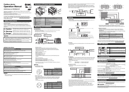
Fieldbus deviceOperation ManualEX250 Series for PROFIBUS DPMounting and InstallationAddress settingBe sure to turn power supply off before setting the switches off before setting the switches of SI unit. Switch installed in cover of SI unit is available for setting of address.InstallationNot having mounting hole, it can’t be set to BUS independently. Be sure to connect manifold to SI unit for setting.And if Input block is unnecessary, connect End plate directly to SI unit.SettingExchange of SI unit•Remove screws from End Plate and release connection of each unit.•Replace old SI unit with new one. (Tie rod does not need to be removed.)•Connect Input Block and End Plate and tighten removed screws by specified tightening torque. (0.6 Nm)Assembly and disconnection of unit Addition of Input Block•Remove screws from End Plate.•Mount attached tie rod.•Connect additional Input Block.•Connect End Plate and tighten removed screws by specified tightening torque. (0.6 Nm)Caution for maintenance(1) Be sure to turn-off all power supplies.(2) Be sure that there is no foreign object in any of units.(3) Be sure that gasket is lined properly.(4) Be sure that tightening torque is according to specification.If these items are not kept, it may lead to the breakage of substrate or intrusion of liquid or dust into the units.LED indicationTroubleshootingTechnical documentation giving detailed troubleshooting information can be found on the SMC website (URL ).SpecificationsPower for SI unit/Input Block: 24 VDC ±20%, 1.1 A or lessInside of SI unit: 0.1 A or lessInput block: 1 A or less (Depending on number of connectingsensors and specifications)Power for solenoid valve: 24 VDC +10%/5%, 2 A or less(Depending on number of solenoid valve station and specifications)Connection load: Solenoid valve with protection circuit for 24 VDC and 1.5 W or less surgevoltage. (made by SMC)Operating ambient temp: -10 to 50 C Storage ambient temp: -20 to 60 C Pollution degree: Pollution degree 3 (UL508)Technical documentation giving detailed specification information can be found on the SMC website (URL ).Outline DimensionsTechnical documentation giving detailed outline dimensions information can befound on the SMC website (URL ).AccessoriesTechnical documentation giving detailed accessories information can be found on the SMC website (URL ).Assembly and disconnection of unitNOTEWhen conformity to UL is necessary the SI unit must be used with a UL1310Class2 power supply.Thank you for purchasing an SMC EX250 Series Fieldbus device (Hereinafter referred to as "SI unit" ).Please read this manual carefully before operating the product and make sure you understand its capabilities and limitations.Please keep this manual handy for future reference.To obtain more detailed information about operating this product,please refer to the SMC website (URL ) or contact SMC directly.These safety instructions are intended to prevent hazardous situations and/or equipment damage.These instructions indicate the level of potential hazard with the labels of"Caution", " Warning" or "Danger". They are all important notes for safety and must be followed in addition to International standards (ISO/IEC) and other safety regulations.OperatorWiringCommunication wiring •Communication connectorM12 5pin reverse (Socket)Example of connected Bus Tee: TURCK VB2/FSW/FKW/FSW45 etc.Power supply wiringPower supply line inside the unit has individual power supplies for solenoid valve actuation (SV power supply) and for Control parts and Input block (SI•SW power supply). Supply 24 VDC for each of them. Either single or dual power supply is available.•Communication connectorM12 5pin (Plug)Example of connected cable: SMC EX500-AP0∗0-S etc.Power for sensor is supplied to sensor connected with Input block. Select sensor concerning voltage drop up to maximum 1 V inside the unit at this moment.If sensor requires 24 V, it is necessary to lower power supply voltage for sensor slightly or secure power supply for sensor separately without going through SI unit so that sensor input voltage can be 24 V with actual loading (allowable voltage of power supply: 19.2 V to 28.8V).gle or dual power supply is available.TerminatorIt is necessary to attach bus terminating resistance to the units located at the ends of transmission line.ConfigurationIn PROFIBUS DP, a device database file called the Generic Station Description (GSD)file provides configuration information specific to the device (ID number, data format,baud rate...).The GSD file of the product depends on the address setting mode (selected by the address setting mode switch).GSD file : SMCA1409.gsd (In hardware setting mode)SMCA1408.gsd (In software setting mode)Assignment of I/O No.Correspondence between output data and valve manifold •Output dataCorrespondence between output data and valve manifold ∗: Each bit of data read into master 4bytes shows ON/OFF of sensor connected to input block.Starting from LSB of first byte (Offset 0), input numbers are assigned to all bits in numeric order.Diagnosis informationDiagnosis information of the SI unit is composed of 6 bytes standard diagnosis information and 7 bytes SI unit status information, 13 bytes in total, as specified in PROFIBUS DP.When the SI unit is in a non-standard state, it will send an error message to the master as diagnosis information, and light up the DIA display.Technical documentation giving detailed diagnosis information and set-up steps information can be found on the SMC website (URL ).Refer to PROFIBUS specifications and manual of the master, etc. for how to refer to diagnosis information on the master.∗: Output numbers are assigned to stations from side D to U of manifold in order. (See manual of each valve manifold for the directions of side D and U)∗: Standard manifold is wired in double. Output numbers are assigned to side A and B alternatively.In case of single solenoid valve, output on side B is free. (Refer to fig.a)∗: Mixed (single and double) wiring is available as long as wiring specifications designate it. This allows output numbers to be specified without having free output. (Refer to fig.b)∗: Each bit of data sent from master (4 bytes) shows ON/OFF (0: OFF, 1: ON) of solenoid valve.Starting from LSB of the first byte (Offset 0), output numbers are assigned to all the bits in numeric order.∗: When software setting mode is selected, address setting switches are not effectual. Moreover,software setting mode and hardware setting mode differ in ID numbers of units.Note: Specifications are subject to change without prior notice and any obligation on the part of the manufacturer.© 2011 SMC Corporation All Rights ReservedAkihabara UDX 15F, 4-14-1, Sotokanda, Chiyoda-ku, Tokyo 101-0021, JAPAN Phone: +81 3-5207-8249 Fax: +81 3-5298-5362URL )(。
DP操作规程

动力定位系统(HDP501)操作规程1.系统启动将UPS电源箱上船电开关和应急开关打开,船电和应急转换开关旋至船电位置处,按UPS控制面板开机按键。
打开控制柜柜门,闭合控制柜右下角的两个空气开关(左边空气开关为控制柜主机的电源开关,右边为运动传感器MRU的电源开关)。
按主/副控制台内的电源按钮,电源指示灯亮,主/副操纵面板和主/副控制台主机上电,显示器显示系统运行封面。
注:启动前尽可能将操纵面板上的独立操纵杆和DP操作控制权转换开关旋至独立操纵杆位置处。
2.仿真训练工作方式系统开机后将出现系统运行封面,在倒计时期间(10秒)按下主控制台操纵面板上的训练工作按键。
综合显示页面状态栏显示仿真工作方式。
利用辅助设定菜单的海洋环境设置,设置海洋环境的仿真数据。
操作员根据需要,选择工作模式,进行DP操纵。
选择多功能菜单中的实船方式,可退出仿真训练方式,进入实船工作方式。
选择多功能菜单中的关闭系统,可退出仿真训练方式。
注:在仿真训练工作方式,只能通过主控台面板进行操作。
3.实船工作方式系统开机后出现系统运行封面,在倒计时期间,不进行任何操作,系统自动进入实船工作方式。
综合显示页面状态栏显示实船工作方式。
系统处于仿真训练方式,选择多功能菜单中的实船方式,进入实船工作方式。
系统处于开机自检工作方式,选择自检菜单的返回系统子菜单,确认后,系统自动进入实船工作方式。
4.独立操纵杆工作方式进入实船工作方式,系统处于主控台操纵下。
将独立操纵杆/DP操作控制权转换开关旋至独立操纵杆位置,系统将处于独立操纵杆工作方式。
在此方式,操纵员利用船上的独立操纵杆系统操纵船的航行,船的推进系统不接受HDP501控制台发出的指令,动力定位控制系统只具有信息综合显示功能。
5.DP工作方式进入实船工作方式,将独立操纵杆/DP操作控制权转换开关旋至DP操作位置,系统将处于DP工作方式。
进行推进器允控请求,在所有推进器允控情况下,才可进行DP操作。
- 1、下载文档前请自行甄别文档内容的完整性,平台不提供额外的编辑、内容补充、找答案等附加服务。
- 2、"仅部分预览"的文档,不可在线预览部分如存在完整性等问题,可反馈申请退款(可完整预览的文档不适用该条件!)。
- 3、如文档侵犯您的权益,请联系客服反馈,我们会尽快为您处理(人工客服工作时间:9:00-18:30)。
第 1 页,共5页 DREHMO 瓹ompact 使用手册
DREHMO ٛ
-Compact
紧凑型电动执行器一体化定位器调试补充说明
DREHMO
版本:1.14 版本日期:2008年05月28日
第 2 页,共5页 DREHMO 瓹ompact 使用手册
在带内置一体化位置控制器的DPR 版本中,必须进行自动校准,以确保最优化控制功能
过程如下:
按下按钮SW1约2秒(如直到D3灯亮)使控制器进入自动校准模式。
在这个过程,控制器进行位置反馈和转向检查,使执行器运行到开位和关位,测量开和关方向的惯性,且将设定参数存入EEPROM 存储器中。
在初始化过程出现错误(如连接或调整)的情况下,初始化过程中断且控制器的D4灯将报告错误类型。
否则,初始化完成,控制器转到调节模式。
如果需要改变控制器的设定参数,请按以下说明进行。
位置控制器的调整(图1)
内置位置控制器对带模拟信号的控制执行器是一个用户友好控制系统。
控制器充分采用高性能RISC 处理器MICROCHIP 的优点来完成所有的功能。
它同时还提供系统的连续自诊断功能,故障信息以及开关次数和控制器运行小时数。
在端子板86/87(GND,-)和88(+)的输入端加模拟信号将导致执行器的输出被复位。
所要求的参数和功能可以使用控制器上功能按钮SW1-SW2和LED 灯 D3-D4来编程,见表1。
控制器设定
控制器的微处理器单元在出厂的编程参数见表1(注2)。
控制器的调整通过按钮和LED 灯完成。
在控制器调整之前,先调整行程开关、力矩开关和位置反馈(行程变送器)。
控制器板上的调整部件和信号部件见图1 。
图
1
第 3 页,共5页 DREHMO 瓹ompact 使用手册
SW1 启动初始化程序,选择设定菜单中允许菜单。
SW2 在选择菜单中设定参数 D1 上电指示
D2 开关方向指示,“开“指示(绿)-“关“指示(红) D3 (黄灯)闪动次数代表选择的菜单
D4 (红灯)闪动次数代表选择菜单中控制器的参数
表1
D3(黄) 闪动次数 设定菜单 D4(红) 闪动次数 设定参数 1闪 0-20Ma 2闪 4-20mA (*)(**) 1闪
控制信号 3闪 0-10V DC
1闪 接收信号SYS ,执行器到开位 2闪 接收信号SYS ,执行器到关位 2闪
故障安全位置 SYS-TEST 3闪 接收信号SYS ,执行器停(*) 1闪 控制信号增加时执行器关 3闪 递增/递减特性 2闪 控制信号增加时执行器开(*) 4闪 控制器的死区 1到10闪 对应控制器死区1-10% (出厂设定为3%)(*)
1闪 窄力矩
2闪 窄行程(*) 3闪 宽力矩 5闪
调节方式
4闪
宽行程
注: 1. 控制器处于自动校准,自动设定反馈类型-电阻/电流
2. (*) 如果用户没有特别说明,出厂设定参数。
3. (**) 输入信号 4 mA—“关”位置
20 mA—“开”位置
控制器的标准设定-在设定参数中出现问题的任何情况下,都可以通过同时按下SW1和SW2,然后给执行器上电来设定标准参数(出厂参数)。
控制器设定过程
在控制器上电,零系统偏差和短时间按SW1约2秒(如直到D3亮)时初始化程序启动。
松开按钮一些缺省菜单启动(通常控制信号),D3开始1闪,以及缺省参数之一(通常是4-20mA 控制信号)启动,D4开始闪动。
这是控制器要求的参数可以根据表1进行改变: .按下SW1,根据D3的闪动次数选择列表菜单
.按下SW2,根据D4的闪动次数选择列表中所要设定的参数。
在根据用户的要求改变参数后,按下SW1按钮约2秒(如直到D3变亮),使控制器进入自动校准。
在
DREHMO瓹ompact 使用手册 第 3 页,共4页
这个过程控制器完成位置反馈和转向检查,设定执行器位置”开”和”关”,测量”开”和”关”方向的惯性,且将设定参数传到EEPROM存储器中。
在初始化过程中出现错误(如处于连接或设定时)的情况下,初始化过程将中断,且控制器的D4灯将报告错误的类型。
否则在初始化过程完成之后,控制器就投入到调节模式。
位置调整及设置
松开紧固螺母,顺时针将手轮摇到阀门全关位置,松开紧固螺母下面的
圆形手动螺母,拨S4凸轮使其刚好压到S4行程开关,拧紧手动螺母,逆
时针摇手轮到阀门全开位置,拨S3凸轮使其刚好压到S3行程开关,行程
调整结束(注:行程的调整应接近90度)。
摇动手轮至全关,用尖嘴钳夹
住电位器输出轴( 注:不要损坏轴上的齿轮)使其转动,用万用表读出
反馈的信号值,在全关位置电位器应为最小值为最理想,调整R1使反馈
到4mA,手轮摇到全开调整R2使反馈到20mA,反复调整R1和R2使其反馈满
足要求,摇动手轮使其停留在中间位置(不要加控制信号),长按SW1
直到D3常亮,松开再长按SW1直到D3常亮,松开后执行器开始自动校正
,自动校正结束后电动门就调整结束(注:如果进不了自动校正,需重新
断送电后重试)。
初始化过程D4灯表示控制器的故障信息
4闪……..力矩开关连接不正确
5闪……..位置反馈连接不正确
8闪……..执行器转动方向错误检测或位置反馈连反了
控制器的编程复位RESET
如果需要,通过按下SW1直到D3 LED开始短闪,这样控制器就可以在不断电的情况下重新启动(如,从设定菜单中不自动校准返回)。
运行状态和故障状态观察
在打开执行器时,可以观察执行器的运行状态和故障状态。
a) D3 LED指示的运行状态
.常亮――控制器调节
.持续不亮――系统偏差处在死区范围内-执行器停止
第4 页,共5页 DREHMO瓹ompact 使用手册
b) D4和D3 LED指示的故障状态-D4常亮,D3 用闪动次数指示故障状态
1闪(重复) “TEST”模式指示-执行器运行到”TEST”菜单中信号(在连接66和86/87端
子时)指定的位置
控制信号消失-执行器运行到TEST”菜单中信号指定的位置 2闪(短停后重
复)
力矩开关有效指示(执行器在中间位置由于力矩开关关断) 4闪(短停后重
复)
5闪(短停后重
位置反馈故障-执行器运行到TEST”菜单中信号指定的位置 复)
控制信号(量程为4-20mA的电流信号校园4mA(3.5mA)) 7闪(短停后重
复)
第5 页,共5页 DREHMO瓹ompact 使用手册。
