MOSFET英文讲义
the power mosfet 应用手册

the power mosfet 应用手册The Power MOSFET Application ManualIntroductionThe Power MOSFET Application Manual is a comprehensive guide that delves into the various applications and uses of Power MOSFETs. This manual aims to provide engineers, designers, and enthusiasts with an in-depth understanding of Power MOSFETs, their characteristics, and how they can be effectively implemented in different electronic systems.Section 1: Understanding Power MOSFETs1.1 What is a Power MOSFET?Power MOSFETs, or Metal-Oxide-Semiconductor Field-Effect Transistors, are electronic devices that offer high efficiency, fast switching speeds, and excellent power handling capabilities. This section delves into the structure and functioning of Power MOSFETs, explaining how they differ from their bipolar transistor counterparts.1.2 MOSFET Characteristics and SpecificationsThis subsection explores the various specifications and characteristics of Power MOSFETs, including voltage ratings, current ratings, on-resistance, gate charge, and thermal considerations. It provides engineers with the necessary knowledge to select the appropriate MOSFETs for different applications.Section 2: Power MOSFET Applications2.1 Switching ApplicationsPower MOSFETs have found extensive use in switching applications, such as motor drives, power supplies, and inverters. This section highlights the advantages of using Power MOSFETs in these applications and provides guidelines for circuit design, gate drive requirements, and considerations for minimizing power losses.2.2 Audio AmplificationPower MOSFETs are also commonly used in audio amplifiers due to their low distortion and high power capabilities. This subsection discusses the design considerations for audio amplifiers, including load matching, biasing, and output protection. It provides engineers with the necessary information to design efficient and high-quality audio amplifiers.2.3 Lighting ApplicationsPower MOSFETs are vital components in various lighting applications, including LED drivers, automotive lighting, and streetlights. This section explores the key considerations for designing lighting circuits using Power MOSFETs, including thermal management, dimming techniques, and EMI suppression.2.4 Power SuppliesPower MOSFETs play a crucial role in power supply designs, offering high efficiency and compact size. This subsection discusses the use of Power MOSFETs in different power supply topologies, such as buck converters, boost converters, and flyback converters. It also addresses the challenges ofdesigning power supplies with Power MOSFETs and provides guidelines for achieving optimal performance.Section 3: Protection and Reliability3.1 Overcurrent and Overvoltage ProtectionTo ensure the reliable operation of circuits using Power MOSFETs, adequate protection mechanisms must be implemented. This section covers the different protection techniques, such as overcurrent and overvoltage protection circuits, along with their advantages and limitations.3.2 Thermal ManagementProper thermal management is essential for preventing Power MOSFETs from overheating and ensuring their longevity. This subsection discusses the thermal behavior of Power MOSFETs and presents various cooling techniques, such as heatsinks, thermal vias, and thermal pads, to efficiently dissipate heat.3.3 ESD ProtectionElectrostatic Discharge (ESD) can pose a significant threat to Power MOSFETs and other sensitive electronic components. This section provides an overview of ESD protection methods and highlights the importance of implementing proper ESD protection measures in Power MOSFET applications.ConclusionThe Power MOSFET Application Manual aims to equip engineers, designers, and enthusiasts with the knowledge and skills necessary toeffectively utilize Power MOSFETs in their electronic designs. By providing insights into the characteristics, applications, and protection considerations, this manual serves as a valuable resource for those looking to optimize the performance and reliability of their circuits.。
MOSFET 内部培训资料(Silikron)

Power To Future 苏州硅能半导体科技股份有限公司SuZhou Silikron Semiconductor CorporationMOSFET Datasheet Parameter&Curve PresentationPDD30th Mar 2010outline•Power electronic systems•Power devices and application requirements•Power device technologies in Si (>99 % of market)-Power diodes These materials constitute confidential information of SILIKRON. These matrials may not be copied or -Thyristor -Bipolar Junction Transistors -Power MOSFET -Insulated Gate Bipolar Transistors (IGBT)Energy efficient power electronic systems•Electric power regulated using power electronics•Significant power losses in semiconductor devices•Device power losses should be minimized •Power devices and application requirements-to improve efficiency and save energy -to reduce system size (market driver)These materials constitute confidential information of SILIKRON. These matrials may not be copied or •Power device development: minimize power losses –whilefulfilling other requirementsPower electronic systemsThese materials constitute confidential information of SILIKRON. These matrials may not be copied or•Semiconductor devices key elements in power electronics •Global device market: 12B USD, growth rate ~ 11%Power semiconductor devices Power devices are switching transistors and diodesOne device per chip or one device per waferThese materials constitute confidential information of SILIKRON. These matrials may not be copied or •Power integrated circuits (Smart Power) also available•Power devices available for ~ 1 A –5,000 A and 30 V -10,000Device type:Planar MOSFETTrench MOSFETSuper Junction MOSFETIGBT: Isolation Gate Bipolar TransistorPower device structureTechnology trends: Rdson perspectiveThese materials constitute confidential information of SILIKRON. These matrials may not be copied orSuper JunctionTechnology trends: switching lossThese materials constitute confidential information of SILIKRON. These matrials may not be copied orVertical DMOS-device feature:Planar DMOS structure introduce:These materials constitute confidential information of SILIKRON. These matrials may not be copied or Check item afterassemblyWafer level check itemVertical DMOS-device feature-RdsonRdson: Rdson= R ch+RA+ Rsource+ RJ+ RD+ Rsub +RwcmlRsource = Source diffusion resistanceRch = Channel resistanceRA = Accumulation resistanceRJ = "JFET" component-resistance of the region between the two body regions RD = Drift region resistanceRsub = Substrate resistanceThese materials constitute confidential information of SILIKRON. These matrials may not be copied orProcess descriptionField oxide Active etch GR implantGR DRV JFET implantGate oxide Poly + Dope Poly etchPower To FutureThese materials constitute confidential information of SILIKRON. These matrials may not be copied or distributed without written permission from SILIKRON.11Process descriptionBody implantBody DRV N+ Photo N+ implant N+ anneal LPTEOS Spacer etch P+ implantPower To FutureThese materials constitute confidential information of SILIKRON. These matrials may not be copied or distributed without written permission from SILIKRON.12Process descriptionBPGS-CVD BPSG flow Contact Contact flow Metal sputter Metal Alloy Back grind Back Si etch Back metalPower To FutureTi+Ni+Ag13These materials constitute confidential information of SILIKRON. These matrials may not be copied or distributed without written permission from SILIKRON.Absolute Maximum RatingsPower To FutureThese materials constitute confidential information of SILIKRON. These matrials may not be copied or SILIKRON Confidential distributed without written permission from SILIKRON.14Electrical Characteristics-1Power To FutureThese materials constitute confidential information of SILIKRON. These matrials may not be copied or distributed without written permission from SILIKRON.15Electrical Characteristics-2Power To FutureThese materials constitute confidential information of SILIKRON. These matrials may not be copied or distributed without written permission from SILIKRON.16Rdson vs. Vdss and Vdss vs. TC1. Vdss对温度具有正的温度系数,应用时应考虑最低的应用环境温度 2. 为减少器件的损耗,需要选择合适的Vdoss(保证雪崩耐量的电压即可) 其数值高时,Rdon也大,增加器件的损耗Power To FutureThese materials constitute confidential information of SILIKRON. These matrials may not be copied or distributed without written permission from SILIKRON.17Vdss vs. Vgs此特性曲线反映的是在规定的工作 电流Id下,外加多少伏的栅极电压,可以 达到饱和的电压Vds(on)区(通态电阻区) *Vgs具有负温度系数,一般为-5mV/CPower To FutureThese materials constitute confidential information of SILIKRON. These matrials may not be copied or distributed without written permission from SILIKRON.18Rdson vs. Tc1. Rdson具有正温度系数,即随温度升高, Rdson变大 2. Rdson随所加的栅极驱动电压Vgs升高, 而减小3. α=Rison(150C)/Rison(25C),对100V以下的产品, α一般为1.7-2Power To FutureThese materials constitute confidential information of SILIKRON. These matrials may not be copied or distributed without written permission from SILIKRON.19Input curveVgs具有负温度系数,即随温度 升高而减小Power To FutureThese materials constitute confidential information of SILIKRON. These matrials may not be copied or distributed without written permission from SILIKRON.20Qg1. Qg为Vgs=XV电压下的栅极电荷总量 2. Qg与测试条件相关,不同的Vds得到不同的Qg 3. 高频特性时(f≥100KHZ)时,Qg是重要的考虑项These materials constitute confidential information of SILIKRON. These matrials may not be copied or distributed without written permission from SILIKRON.21Power To FutureInternal Diode Between Drain and Source1. 此寄生二极管的额定电流值Idr与正 向 漏极电流额定值Id相同 2. 当栅极电压Vgs=0或负值时,与二极管 的特性相同; 当栅极电压Vgs为正值时,可以得 到更小的Vsd电压,此时Vsd=Idr*RdsPower To FutureThese materials constitute confidential information of SILIKRON. These matrials may not be copied or distributed without written permission from SILIKRON.22SOA1. ①区受最大电流Id、Id(Pulse) 限制区域 2. ②区是受导通电阻最大(Rdson) 理论限制区,即 Id=Vds/Rdson 3. ③区受沟道损耗限制区域4. ④在连续运行或脉宽较长时,类 似晶体管二次击穿区 5. 域 ⑤区是受最大耐压Vds限制区Power To FutureThese materials constitute confidential information of SILIKRON. These matrials may not be copied or distributed without written permission from SILIKRON.23Rjc此特性曲线是为计算器件在运行状态时的沟道温度Tch,横轴表示 脉宽PW时间,1shot single pulse(单脉冲)和反复运行的时间These materials constitute confidential information of SILIKRON. These matrials may not be copied or distributed without written permission from SILIKRON.24Power To FutureEASPower To FutureThese materials constitute confidential information of SILIKRON. These matrials may not be copied or distributed without written permission from SILIKRON.25ESDESD保护二 极管Power To FutureThese materials constitute confidential information of SILIKRON. These matrials may not be copied or distributed without written permission from SILIKRON.26Power To FutureThanks!Power To FutureThese materials constitute confidential information of SILIKRON. These matrials may not be copied or distributed without written permission from SILIKRON.27。
mos场效应管简介及原理(英文)
MOS场效应管简介及原理(英文)【简介】MOS场效应晶体管(Metal-Oxide-Semiconductor Field-Effect Transistor)是一种常用于电子电路的晶体管。
它是一种小型、高度集成的设备,能够控制通过它的电流流动。
MOSFET被广泛应用于数字和模拟电子学、通信系统和电力电子等领域。
【原理】MOSFET的基本工作原理是通过在栅极电极施加电压来控制通过源极和漏极的电导。
通过栅极施加的电压决定了通过MOSFET的电流量。
MOSFET有两种类型:N型(负型)和P型(正型)。
N 型MOSFET的基板材料为n型半导体材料(含电子),而P 型MOSFET的基板材料为p型半导体材料(含空穴)。
这些材料的选择取决于应用,因为它们具有不同的电气特性。
MOSFET在电子电路中广泛应用,因为它们具有小型化、高速度和低功耗等优点。
它们还可以使用现代半导体制造技术轻松制造,使其成本效益高,并且广泛可用。
【英文】MOSFET (Metal-Oxide-Semiconductor Field-Effect Transistor) is a type of transistor commonly used in electronic circuits. It is a small, highly integrated device that can control the flow of electrical current through it. MOSFETs are used in awide range of applications, including digital and analog electronics, communication systems, and power electronics.The basic principle of operation of a MOSFET is that it controls the flow of electrical current through the gate electrode, which is insulated from the source and drain by a thin oxide layer. When a voltage is applied to the gate electrode, a current flows through the channel between the source and drain, causing the MOSFET to conduct electricity. The voltage applied to the gate electrode determines the amount of current that flows through the MOSFET.There are two main types of MOSFETs: N-type (for negative) and P-type (for positive). N-type MOSFETs have an n-type semiconductor material (containing electrons) as the substrate, while P-type MOSFETs have a p-type semiconductor material (containing holes) as the substrate. These types of materials are chosen based on the application, as they have different electrical properties.MOSFETs are widely used in electronic circuits because of their small size, high speed, and low power consumption. They are also easy to fabricate using modern semiconductor manufacturing techniques, making them cost-effective and widely available.。
功率MOSFET基础知识
功率MOSFET 基础知识自1976年开发出功率MOSFET 以来,由于半导体工艺技术的发展,它的性能不断提高:如高压功率MOSFET 其工作电压可达1000V ;低导通电阻MOSFET 其阻值仅lOm Ω;工作频率范围从直流到达数兆赫;保护措施越来越完善;并开发出各种贴片式功率MOSFET (如Siliconix 最近开发的厚度为1.5mm “Little F oot 系列)。
另外,价格也不断降低,使应用越来越广泛,不少地方取代双极型电晶体。
功率MOSFET 主要用于电脑周边(软、硬驱动器、印表机、绘图机)、电源(AC /D C 变换器、D C /D C 变换器)、汽车电子、音响电路及仪器、仪表等领域。
本文将介绍功率MOSFET 的结构、工作原理及基本工作电路。
以下内容需要回复才能看到什么是MOSFET“MOSFET ”是英文MetalOxide Semicoductor Field Effect Transistor 的缩写,译成中文是“金属氧化物半导体场效应管”。
它是由金属、氧化物(SiO2或SiN)及半导体三种材料制成的器件。
所谓功率MOSFET (Power MOSFET )是指它能输出较大的工作电流(几安到几十安),用于功率输出级的器件。
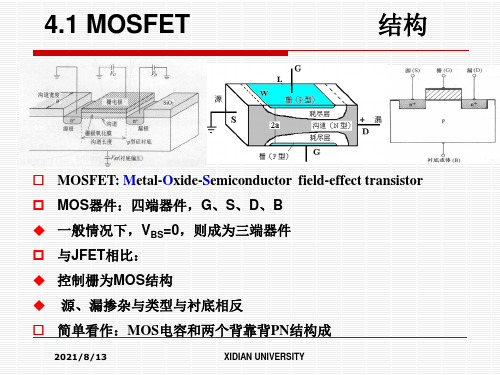
MOSFET 的结构图1是典型平面N 沟道增强型MOSFET 的剖面图。
它用一块P 型硅半导体材料作衬底(图la),在其面上扩散了两个N 型区(图lb),再在上面覆盖一层二氧化硅(SiQ2)绝缘层(图lc),最后在N 区上方用腐蚀的方法做成两个孔,用金属化的方法分别在绝缘层上及两个孔内做成三个电极:G(栅极)、S(源极)及D(漏极),如图1d 所示。
h tt p://z gj dw x.5d 6d .c o m /b bs .p h p从图1中可以看出栅极G 与漏极D 及源极S 是绝缘的,D 与S 之间有两个PN 结。
一般情况下,衬底与源极在内部连接在一起。
MOSFET_notes_1
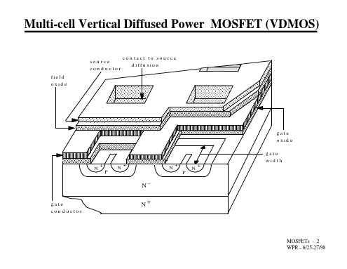
• Mobilty decreases, especially via carriercarrier scattering leead to linear transfer curve in power devices instead of square law transfer curve of logic level MOSFETs.
MOSFETs - 4 WPR - 6/25-27/98
N i D
N+
drain
MOSFET I-V Characteristics and Circuit Symbols
i D
ohmic V [v - V = v ] GS(th) GS DS GS5 active V GS4
i
D
actual
V GS3
4 1.5x10 V/cm
electric field
• At larger carrier densities, free carriers collide with each other (carrier-carrier scattering) more often than with lattice and mobility decreases as a result.
• MOSFET equivalent circuit valid for on-state (triode) region operation.
gd I = f(V ) GS D
• MOSFET equivalent circuit valid for offstate (cutoff) and active region operation.
MOSFETs - 11 WPR - 6/25-27/98
MOSFET教程
MOSFET教程MOSFET是Metal-Oxide-Semiconductor Field-Effect Transistor的缩写,是一种常用的电子器件。
它是一种由金属-氧化物-半导体结构组成的场效应晶体管,它的特点是高频特性好、占用面积小、输入电阻高、工作电压低等。
MOSFET广泛应用于各种电子设备和电路中,如功率放大、开关、逻辑门等。
MOSFET的结构由P型或N型半导体基片构成,其中夹着一层非晶态或多晶态氧化铝或氮化硅形成的绝缘层。
绝缘层上覆盖有金属结构作为栅极,这个金属结构是通过一两个小孔与下面的半导体相连接。
这样,当栅极电压改变时,可以通过改变栅电压控制半导体中的电流。
MOSFET有四个主要电极:栅极(Gate),漏极(Drain),源极(Source),和衬底(Substrate)。
栅极用于控制器件的导通和截止,漏极和源极用于连接外部电路的通路,衬底则提供基片极性。
根据栅极电压与漏极电压之间的关系,MOSFET可以分为三种工作区:截止区、线性区和饱和区。
当栅极电压低于阈值电压时,MOSFET处于截止区。
此时,MOSFET的导通能力非常小,几乎没有漏极电流。
这种特性使得MOSFET在开关电路中特别有用。
当栅极电压在阈值电压和漏极电压之间时,MOSFET处于线性区。
此时,MOSFET的电流与栅极电压成正比,使得MOSFET可以在放大器电路和线性增强器中使用。
当栅极电压高于漏极电压时,MOSFET处于饱和区。
在饱和区,MOSFET的电流几乎不受栅极电压的影响,因此可以作为开关电路中的高电流驱动器使用。
在实际应用中,选择正确的MOSFET非常重要。
根据应用需求,可以选择不同类型的MOSFET,如N沟道MOSFET和P沟道MOSFET。
此外,还可以选择不同的封装形式,如DIP、SMD或TO-220等。
在使用MOSFET时,还需要考虑一些特殊的电路设计技巧。
例如,在开关电路中,要合理选择电阻分压电路、滤波电容或磁珠等来保护MOSFET免受过大电压或电流的侵害。
MOSFET Introduction
4.Igss : 為gate周圍所介入的氧化膜的漏電流,此值越小越好,標準值在10nA 5.Rds(on) :此為Power MOSFET在導通時的電阻成分
Dynamic characteristics
1.gfs :可定義為drain 電流對gate電壓的變化率,在切 換電路中gfs 越高越好 2. .Ciss:此為power mosfet 在OFF狀態下gate輸入容量,
注意: Rds(on)通常是以Junction溫度為25度C時的最大 值規定,但實際應用上應考慮Junction溫度為150度 C時的數值,矽材質的Rds(on)對溫度而言約以 0.6%/度C比例增加.假設輸出電流固定,則溫度上 升, Rds(on)上升,則飽和損失Psat=Id^2*Rds(on)會 增加,所以設計不應該以Junction溫度為25度C時的 Rds(on)電阻做為設計,應考慮150度C時的Rds(on) 為基準
MOSFET Introduction
MOSFET之架構
MOSFET是在源極(Source)區與汲極(Drain)區的半導 體基板表面覆蓋在一層薄薄的二氧化矽(SiO2)作為絕 緣層,再把金屬沈積在氧化層上形成元件的閘極(Gate) 而製成。
NMOS結構及電路符號 結構及電路符號
PMOS結構及電路符號 PMOS結構及電路符號
T fixed: Duty cycle越大 熱阻越大 Duty cycle fixed: T越大 熱阻越大 Rthjc Rthcr Rthra Junction--------------------------Case----------------------------Heat sink---------------------------------Ambient 6.熱阻(junction to ambient) :不使用Heat sink的情況下,由Junction到空氣周圍熱阻 7.Power dissipation : Pd=(Tjmax-25)/Rthjc 以此Power MOSFET為例:Pd=(175-25)/2=75W
半导体英文课件 MOSFET
Slide 6-3
Early Patents on the Field-Effect Transistor
Modern Semiconductor Devices for Integrated Circuits (C. Hu)
Slide 6-4
Early Patents on the Field-Effect Transistor
Solution:
(Vgs Vt 0.2) / 6Toxe = 1.5 V /1210-7 cm = 1.25MV/cm
1 MV is a megavolt (106 V). From the mobility figure,
mns=190 cm2/Vs, which is several times smaller than
Chapter 6 MOSFET
The MOSFET (MOS Field-Effect Transistor) is the building block of Gb memory chips, GHz microprocessors, analog, and RF circuits.
Match the following MOSFET characteristics with their applications:
Modern Semiconductor Devices for Integrated Circuits (C. Hu)
Slide 6-7
CMOS (Complementary MOS) Inverter
Vd d
PFET S
Vi n
D
Vo ut
D
S NFET
0V
C:
capacitance (of interconnect,
MOSFET Introduction
DC/DC Switching
1. 2. 3. 4. Voltage rating Current rating Thermal rating High and Low-side MOS concern
Duty cycle < 50% Duty cycle > 50%
Qgd
High-side MOS Low-side MOS Example Priority High Priority Low
Lgate Phase Vin
Irms = (1 − D)(Iout −
2
Iripple 12
2
)
IL
Iripple Iout
Irms ≈ Iout (1 − D)
For Lower MOSFET, conduction loss is the largest power dissipation
IsFET
DCIN1 1 2 3 4 5 1 ACES-CON5-5-GP 20.80399.005 R293 1 2 4K7R2J-2-GP AD_JK AD+_2 R277 200KR2J-L1-GP 2 1 DY DY EC53 EC9 1 SCD1U25V3ZY-1GP 2 SCD1U25V3ZY-1GP C311 SC1000P50V3JN-GP 1 1 1 2 3 4 AD+ AD+
Turn off Loss
Poff1 = Io Qgd Qgs2 VinFsw + Io VinFsw 2ig 2ig
t 2 − t1 =
Qgd ig
Qgs2 t3 − t 2 = ig
MOSFET Datasheet
Lower MOSFET Conduction Loss
MOSFET
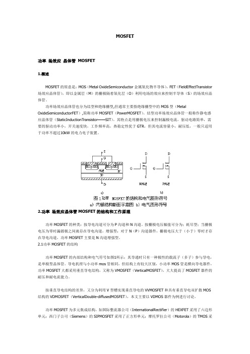
MOSFET功率场效应晶体管MOSFET1.概述MOSFET的原意是:MOS(Metal OxideSemiconductor金属氧化物半导体),FET(FieldEffectTransistor 场效应晶体管),即以金属层(M)的栅极隔着氧化层(O)利用电场的效应来控制半导体(S)的场效应晶体管。
功率场效应晶体管也分为结型和绝缘栅型,但通常主要指绝缘栅型中的MOS型(Metal OxideSemiconductorFET),简称功率MOSFET(PowerMOSFET)。
结型功率场效应晶体管一般称作静电感应晶体管(StaticInductionTransistor——SIT)。
其特点是用栅极电压来控制漏极电流,驱动电路简单,需要的驱动功率小,开关速度快,工作频率高,热稳定性优于GTR,但其电流容量小,耐压低,一般只适用于功率不超过10kW的电力电子装置。
2.功率场效应晶体管MOSFET的结构和工作原理功率MOSFET的种类:按导电沟道可分为P沟道和N沟道。
按栅极电压幅值可分为;耗尽型;当栅极电压为零时漏源极之间就存在导电沟道,增强型;对于N(P)沟道器件,栅极电压大于(小于)零时才存在导电沟道,功率MOSFET主要是N沟道增强型。
2.1功率MOSFET的结构功率MOSFET的内部结构和电气符号如图1所示;其导通时只有一种极性的载流子(多子)参与导电,是单极型晶体管。
导电机理与小功率mos管相同,但结构上有较大区别,小功率MOS管是横向导电器件,功率MOSFET大都采用垂直导电结构,又称为VMOSFET(VerticalMOSFET),大大提高了MOSFET器件的耐压和耐电流能力。
按垂直导电结构的差异,又分为利用V型槽实现垂直导电的VVMOSFET和具有垂直导电双扩散MOS 结构的VDMOSFET(VerticalDouble-diffusedMOSFET),本文主要以VDMOS器件为例进行讨论。
(完整)半导体器件物理MOSFET精品PPT资料精品PPT资料
器件预VD 夹 SVD 断 (Ssa),t, IDID(sa)t VD(Ssa)tVGS VT
沟道夹断点X: 反型层电荷密度刚好≈0→VGX=VT,
→ VGS-VXS=VT
→ VXS=VGS-VT=VDS(sat)
2021/8/13
4.1 MOSFET
ID随VDS的变化(4)
饱和区
原沟道区:导电沟道区和夹断区。电流被夹断了吗? 导电沟道区可导电,又有电势差,所以有电流,根据电流连续性原理,
4.1 MOSFET
0栅压是否存在反型沟道分:
MOSFET分类(2)
n沟增强型MOSFET
零栅压时不存在反型沟道, VTN>0, 加栅压VGS>VTN, 沟道开启
n沟耗尽型MOSFET
零栅压时已存在反型沟道, VTN<0 加栅压VGS<VTN, 沟道关闭
思考:不进行专门的N型掺杂,能否形成耗尽型NMOS?
1 MOSFET MOSFET分类(5)
1 MOSFET
跨导:模型
p沟增强型MOSFET
1 MOSFET
I-V特性:基本假设
漂移到夹断点的电子在夹断区大电场的作用下被扫向漏极,形成ID
VDS<0, ID<0
n沟道MOSFET:NMOS
加栅压VGS>VTP, 沟道关闭
单位 S(西门子),一般为几毫西 (mS)
2021/8/13
4.1 MOSFET
MOSFET分类(3)
p沟增强型MOSFET
零栅压时不存在反型沟道 VTP<0 加栅压VGS<VTP, 沟道开启
2021/8/13
p沟耗尽型MOSFET
零栅压时存在反型沟道 VTP>0 加栅压VGS>VTP, 沟道关闭
MOSFET Introduction

MOSFET規格表看法 MOSFET規格表看法
Off characteristics: Vdss:Power MOSFET的Drain-Source間所能忍受的最大 電壓,主要受制內藏於Power MOSFET內的反body diode的耐壓。 IDSS:所謂的漏電流,通常很小,但有時確保耐壓,在晶片 周圍設計,多少會有漏電流存在,但在實際應用上並 沒有什麼問題。 IGSS:為gate周圍所介入的氧化膜的漏電流,此值越小越 好,標準值在10nA。
MOSFET Introduction
HTDE 2011-01-24
Agenda
1. MOSFET Theory 2. MOSFET Type
3. MOSFET Selection
4. SA MOSFET Measurement 5. MOSFET Failure Analysis
MOSFET Theory
Dual-Gate MOSFETS 電路圖
增強型MOSFET
增強型MOSFET
(E-MOSFET, Enhancement MOSFET)
E-MOSFETS的基本結構圖
◆E-MOSFET只有增強工作模式,沒有空乏工作模式。在結構 上與D-MOSFET不同的是,它沒有通道。 ◆在n通道元件的閘極加上超過臨界值的正電壓,可以在 緊鄰SiO2層的基質層區域,產生由負電荷構成的薄層 ,因而感應生成(induce)一個通道 ◆繼續增加閘極對源極的正電壓,會吸引更多電子到通 道區,通道的導電性因此增強。閘極電壓低於臨界值 時,則沒有通道產生。
On characteristics: Vgs(th):此為Power MOSFET開始ON時的輸入電壓值, 此表示的為在Junction為25度C時的最大值與最小 值。
mos场效应管简介及原理(英文)
mos场效应管简介及原理(英文)Introduction to MOS Field-Effect Transistor (MOSFET)A metal-oxide-semiconductor field-effect transistor (MOSFET) is a key electronic component widely used in various applications such as amplification, switching, and digital logic circuits. It offers several advantages over other types of transistors, including low power consumption, high input impedance, and high noise immunity. MOSFETs are fundamentally based on the field effect, where the conductivity of a semiconductor channel is controlled by the electric field generated by a gate voltage.Principle of Operation:A MOSFET consists of a source, a drain, a gate, and a thin layer of insulating material known as the oxide layer or gate dielectric between the channel and the gate. The channel is typically made of a semiconductor material such as silicon. The conductivity of the channel is determined by the presence or absence of majority carriers, which can be either electrons (n-type MOSFET) or holes (p-type MOSFET). The gate voltage controls the amount of charge carriers in the channel, thereby controlling the current flow between the source and drain.When the gate voltage is lower than the threshold voltage (Vth), the MOSFET operates in the cutoff region, with no current flowing between the source and drain. In this state, the channel is completely depleted of carriers, and the MOSFET behaves as an open switch.As the gate voltage exceeds the threshold voltage, the MOSFET enters the saturation region, and a conductive channel is formed between the source and drain. The channel acts as a low-resistance path for current flow, allowing a controlled current to pass through the transistor. Increasing the gate voltage beyond the threshold voltage further enhances the conductivity of the channel, leading to an increase in current flow.Types of MOSFETs:1. Enhancement-mode MOSFET (E-MOSFET): This is the most common type of MOSFET, where an external voltage must be applied to the gate to allow significant current flow between the source and drain. The threshold voltage for an E-MOSFET is typically positive for n-type and negative for p-type transistors.2. Depletion-mode MOSFET (D-MOSFET): Unlike E-MOSFETs, this type of MOSFET is normally conducting without any external voltage applied at the gate. To turn off the transistor, a negative voltage is applied to the gate-source junction, depleting the carriers from the channel.Applications:1. Amplification: MOSFETs are commonly used as amplifiers in audio systems, due to their high input impedance and low power consumption. They can amplify small input signals to a higher output level, making them suitable for audio applications.2. Switching: MOSFETs are widely used for switchingapplications, as they can handle high voltages and currents with low power dissipation. Their fast switching speed and low on-resistance make them ideal for power electronics and integrated circuits.3. Digital Logic: MOSFETs form the building blocks of digital logic circuits, such as inverters, NAND gates, and NOR gates. They allow for the implementation of complex digital systems, such as microprocessors and memory devices.In summary, MOSFETs are essential electronic components that offer numerous advantages due to their field-effect principle. They find applications in various domains, including amplification, switching, and digital logic circuits. Understanding the working principle of MOSFETs is crucial in designing efficient and reliable electronic systems.。
第三讲MOS电路MOSCircuits31MOS管(TheMOSFET
第三讲 MOS 电路(MOS Circuits )3.1 MOS 管(The MOSFET )MOS 管的全称是金属氧化物半导体场效应晶体管(metal-oxide-semiconductor field-effect transistor )。
MOS 管是一种三端半导体器件。
MOS 管的三个端子分别叫做栅极(gate, G )、漏极(drain, D )和源极(source, S )。
本讲义只介绍用途广泛的增强型MOS 管。
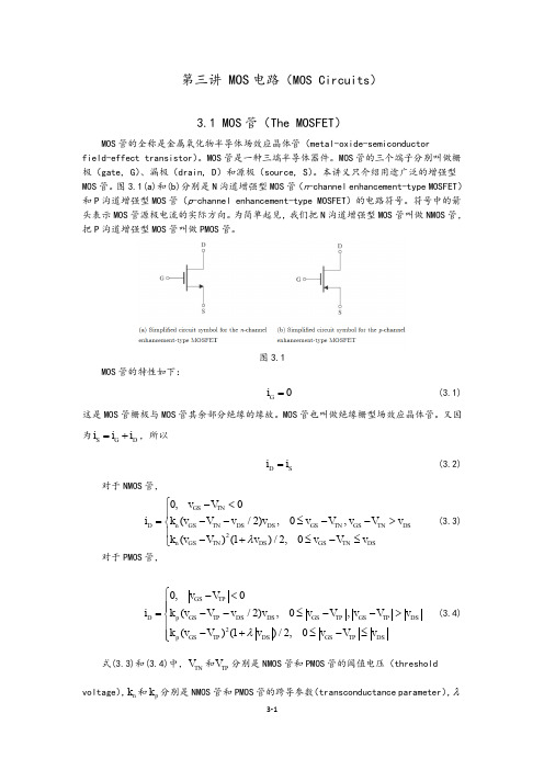
图3.1(a)和(b)分别是N 沟道增强型MOS 管(n -channel enhancement-type MOSFET )和P 沟道增强型MOS 管(p -channel enhancement-type MOSFET )的电路符号。
符号中的箭头表示MOS 管源极电流的实际方向。
为简单起见,我们把N 沟道增强型MOS 管叫做NMOS 管,把P 沟道增强型MOS 管叫做PMOS 管。
图3.1MOS 管的特性如下:0G i = (3.1)这是MOS 管栅极与MOS 管其余部分绝缘的缘故。
MOS 管也叫做绝缘栅型场效应晶体管。
又因为S G D i i i =+,所以D S i i = (3.2)对于NMOS 管,20,0(/2),0,()(1)/2,0GS TN D n GS TN DS DS GS TN GS TN DS n GS TN DS GS TN DSv V i k v V v v v V v V v k v V v v V v λ⎧-<⎪=--≤-->⎨⎪-+≤-≤⎩ (3.3)对于PMOS 管,20,0(/2),0,()(1)/2,0GS TP D p GS TP DS DS GS TP GS TP DS p GS TP DS GS TP DS v V i k v V v v v V v V v k v V v v V v λ⎧-<⎪⎪=--≤-->⎨⎪-+≤-≤⎪⎩(3.4)式(3.3)和(3.4)中,TN V 和TP V 分别是NMOS 管和PMOS 管的阈值电压(thresholdvoltage ),n k 和p k 分别是NMOS 管和PMOS 管的跨导参数(transconductance parameter ),λ是MOS 管的沟道长度调制参数(channel-length modulation parameter )。
Chapter 22 Power MOSFETs
5. Lightly doped drain drift region. Determines blocking voltage rating.
Copyright © by John Wiley & Sons 2003
MOSFETs - 3
Alternative Power MOSFET Geometries
SiO 2
+ N P N
VGG2 +
N
depletion layer boundary
+ + + + + + + + + + + • V al ue det er mi ned by sev er al f act or s
1. Ty pe of mat er i al used f or gat e conduct or
• In MOSFET channel, J = q µn n E = q n v n ; v elocit y v n = µn E
• Velocit y sat urat ion means t hat t he mobilit y µn inv ersely proport ional t o elect ric field E.
+ +++
++ ++
++
SiO 2
VGG3 + + + + + + ++ ++ ++
N+ P N
ionized ac ce pt ors
半导体英文课件 (7)MOSFETs in ICs
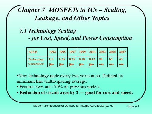
-0.10 -0.15 -0.20 -0.25
0.01
Vds = 50mV Vds = 1.0V
0.1
1
Lg (um)
K. Goto et al., (Fujitsu) IEDM 2003 65nm technology. EOT=1.2nm, Vdd=1V
• Question: Why data is plotted against Lg, not L?
another capacitance in parallel with Cdep
S
60mV
1
Cdep
dQint Coxe
/ ds
Modern Semiconductor Devices for Integrated Circuits (C. Hu)
Slide 7-9
7.3 Vt Roll-off
2003 90
37/65
2005 65
26/45
2007 45
22/37
2010 32
16/25
2013 22
13/20
EOTe(nm) (HP/LSTP) 1.9/2.8 1.8/2.5 1.2/1.9 0.9/1.6 0.9/1.4
VDD (HP/LSTP)
1.2/1.2 1.1/1.1 1.0/1.1 1.0/1.0 0.9/0.9
Vg1 Vg2>Vg1
• Interface states may be filled by electrons or empty
depending on its energy relative to EF, i.e., depending on Vg.
• dQint/d s (number or interface state per eV-cm2) presents
彻底读懂并理解MOSFET的Datasheet(规格书)
a
标准化 RDS(ON) = f(Tj)
1000 Ciss
100
Coss Crss
10 0 20 VDS / V 40
图.10典型电容, Ciss, Coss, Crss. C = f(VDS); 状 态: VGS = 0 V; f = 1 MHz
-60 -20 20 60 Tj / C 100 140 180
10 9 8 0.5 RDS(ON) / Ohm VGS / V = 3 3.5 4 4.5 5 0.3 10 0.2 7 6 5 4 3 2 1 0
gfs / S
0.4
2.5
0 0.1
2
4
6
8
10 12 ID / A
14
16
18
20
0 0 4 8 12 16 ID / A 20 24 28 10000
ID / A 24 20 16 12 8 3 10 7 VGS / V = 4 5
VGS(TO) / V max.
4 0 2 0 2 4 VDS / V 6 8 10
2
图.6 典型的输出特性Tj = 25 ˚C. ID = f(VGS); 参数VGS
typ.
1
min.
0 -60 -20 20 60 Tj / C 100 140 180
图.5 次开启漏极电流 ID = f(VGS); 状态 : Tj = 25 ˚C; VDS = VGS
(图.3)的表示漏极电流为 VGS 的函数说明典型的传 输特性。(图.4)表示栅极开启电压随着结温而变化。 在次开启传导时,(图5)表示在VGS电平低于门槛时 漏极电流怎样随着栅源电压变化。 断电状态时泄漏电流是漏源和栅源在各自所能承受最 大电压情况下所规定的。注意到尽管栅源泄漏电流以 十 亿分之一安培为单位表示,它们的值遵循兆分之一 安培 而变化。
- 1、下载文档前请自行甄别文档内容的完整性,平台不提供额外的编辑、内容补充、找答案等附加服务。
- 2、"仅部分预览"的文档,不可在线预览部分如存在完整性等问题,可反馈申请退款(可完整预览的文档不适用该条件!)。
- 3、如文档侵犯您的权益,请联系客服反馈,我们会尽快为您处理(人工客服工作时间:9:00-18:30)。
where Qn is the charge per unit area
EECS40, Fall 2003
MOSFET as a Controlled Resistor (cont’d)
ID = V DS R DS
L /W L /W = µ n Qi µ C (V − V − V DS ) n ox GS T 2
average value of V(x)
R DS = R s ( L / W ) =
V W I D = µnCox (VGS − VT − DS )VDS L 2
We can make RDS low by • applying a large “gate drive” (VGS − VT) • making W large and/or L small
v is not proportional to E, due to velocity saturation
EECS40, Fall 2003
Lecture 22, Slide 12
Prof. King
Consequences of Velocity Saturation
1. ID is lower than that predicted by the mobility model 2. ID increases linearly with VGS − VT rather than quadratically in the saturation region
(Holes flow from SOURCE to DRAIN when VG < VT )
• The BODY terminal is usually connected to a fixed potential.
– For an n-channel MOSFET, the BODY is connected to 0 V – For a p-channel MOSFET, the BODY is connected to VDD
What Happens at Larger VDS?
VGS > VT : VDS = VGS–VT
Inversion-layer is “pinched-off” at the drain end
VDS > VGS–VT
As VDS increases above VGS–VT ≡ VDSAT, the length of the “pinch-off” region ∆L increases:
» Rabaey et al.: Chapter 3.3.2 » Schwarz & Oldham: Chapter 13.4 » Howe & Sodini: Chapter 4.3
EECS40, Fall 2003 Lecture 22, Slide 1 Prof. King
MOSFET Terminals
S n+
-
VGS G VDS > VGS - VT D
+
I DSAT = µ nCox
W (VGS − VT )2 2L
VGS - VT
n+
pinch-off region
EECS40, Fall 2003 Lecture 22, Slide 9 Prof. King
ID vs. VDS Characteristics
ID ID = ID′(1 + λVDS)
λ is the slope
ID′ is the intercept
VDS
EECS40, Fall 2003
Lecture 22, Slide 11
Prof. King
Current Saturation in Modern MOSFETs
• In digital ICs, we typically use transistors with the shortest possible gate-length for high-speed operation. • In a very short-channel MOSFET, ID saturates because the carrier velocity is limited to ~107 cm/sec
process transconductance parameter
2) Saturation Region: VDS > VGS − VT
′W kn (VGS − VT )2 2 L ′ = µ n C ox where k n I DSAT =
EECS40, Fall 2003
“CUTOFF” region: VG < VT
• The voltage applied to the GATE terminal determines whether current can flow between the SOURCE & DRAIN terminals.
– For an n-channel MOSFET, the SOURCE is biased at a lower potential (often 0 V) than the DRAIN
Lecture 22, Slide 4 Prof. King
Sheet Resistance Revisited
Consider a sample of n-type semiconductor: V I
+
_
W
homogeneously doped sample
t
L
Rs =
ρ
t
=
1 1 1 = = σt qµn nt µnQn
• As VDS increases, the inversion-layer charge density at the drain end of the channel is reduced; therefore, ID does not increase linearly with VDS. • When VDS reaches VGS − VT, the channel is “pinched off” at the drain end, and ID saturates (i.e. it does not increase with further increases in VDS). + –
Note: Electrons are swept into the drain by the E-field when they enter the pinch-off region.
EECS40, Fall 2003 Lecture 22, Slide 8 Prof. King
Summary of ID vs. VDS
OUTLINE
– The MOSFET as a controlled resistor – Pinch-off and current saturation – Channel-length modulation – Velocity saturation in a short-channel MOSFET Reference Reading
Lecture #22
ANNOUNCEMENTS
• Contact Dave Nguyen (nguyendt@uclink) if you lost a calculator in the lab • The EECS40 Course Reader (containing supplemental reading from Schwarz & Oldham) is now available at Copy Central, 2483 Hearst Ave. • Try the educational applets available online! (Visit the class website.)
The MOSFET ID-VDS curve consists of two regions:
1) Resistive or “Triode” Region: 0 < VDS < VGS − VT
V W VGS − VT − DS VDS L 2 ′ = µ n C ox where k n ′ I D = kn
Lecture 22, Slide 3
Prof. King
The MOSFET as a Controlled Resistor
• The MOSFET behaves as a resistor when VDS is low:
– Drain current ID increases linearly with VDS – Resistance RDS between SOURCE & DRAIN depends on VGS
Prof. King
Lecture 22, Slide 10
Channel-Length Modulation
If L is small, the effect of ∆L to reduce the inversion-layer “resistor” length is significant → ID increases noticeably with ∆L (i.e. with VDS)
EECS40, Fall 2003
Lecture 22, Slide 2
Prof. King
MOSFET Circuit Symbols
NMOS n+ poly-Si n+ p-type Si PMOS p+ poly-Si p+ n-type Si p+ n+
