ALPHA5ALPHA5智能,FALDIC-αβWGY□伺服电机手册[英语和日语也显示(FALDIC-α)
富士AC伺服系统FALDIC-W系列用户手册 伺服机构的调整
6 伺服机构的调整6 - 1 调整顺序6 - 2 简易调整6 - 3 模式运行6 - 4基本调整6 - 5应用调整6 - 6要求快速应答时的调整6 - 7超程时的调整(仅限位置控制)6 - 8缩短匹配时间时的调整(仅限位置控制)6 - 9调整参数的标准值6.1 调整顺序当驱动伺服电机时,为可靠地执行来自上位控制装置的命令,需要对伺服放大器进行调整。
调整基本上请按下列顺序进行。
6.2 简易调整6.2.1 什么是简易调整即使与上位控制装置未连接,也可自动进行往复动作,自动进行自整定。
即使在上位控制装置的程序尚未完成的状态下,也可事先使电机动作,还可进行自整定,因此,有利于缩短设置调整的时间。
<只靠放大器和电机,也可以进行往复动作/自整定!!>伺服放大器伺服电机往复动作按「简易调整」(6.2项)进行调整开始按「基本调整」(6.4项)进行操作按「应用调整」(6.5项)进行操作按「要求快速应答时的调整」(6.6项)进行操作结束是否否否是是是6.2.2 简易调整的动作模式简易调整方面有2个动作模式,可利用触摸面板或电脑编程器进行操作。
(1) 慢运行・・・・以10r/min(固定)速度,进行1个往复动作。
可进行旋转方向和行程的确认。
(2) 简易调整・・・进行25次往复动作。
在此期间,自动进行自整定。
基本上请用慢运行确认旋转方向和行程之后,再执行「简易调整」操作。
以「慢运行」确认旋转方向和行程 以10r/min 速度缓慢移动自动进行自整定利用触摸面板的简易调整的操作方法。
1点参考说明以「简易调整」自动进行自整定闪亮 简易调整慢运行 ①过程选择的显示②脱机的显示闪亮(脱机)ENT(1秒以上)ENT 时起动③动作中的显示④正常结束用MODE 键返回至②用MODE 键 中途停止简易调整 慢运作6.2.3 简易调整时的注意点简易调整时,由于是利用伺服放大器的功能自动运行,因此,在安全方面应予以高度重视。
当电机振动,预计对机械设备会产生不良影响时,可在CONT信号中,分配出伺服运行(RUN)信号,或紧急停车(EMG)信号,在接通此信号的时,再实施简易调整。
维智WSDA系列伺服驱动器用户手册(EtherCAT总线通信型)-R4
维智WSDA系列伺服驱动器用户手册(EtherCAT总线通信型)版次:2020年10月12日第4版作者:产品应用测试部上海维宏电子科技股份有限公司目录1 安全注意事项 (1)1.1 警告 (1)1.2 注意 (2)2 基本信息 (3)2.1 前面板结构 (3)2.2 铭牌 (4)2.3 控制模式 (5)2.4 规格与功能 (5)2.4.1 基本规格 (5)2.4.2 从站规格 (7)2.4.3 基本功能 (8)2.4.4 保护功能 (8)2.5 产品安装 (8)2.6 系统接线图 (10)3 配线 (13)3.1 主回路接线 (13)3.1.1 端子 (13)3.1.2 电线规格 (14)3.1.3 接线说明 (17)3.2 USB通讯接口CN1接线 (18)3.2.1 端口定义 (18)3.2.2 线缆 (19)3.3 总线接口 CN2A/B 接线 (20)3.3.1 接线图 (20)3.3.2 线缆 (20)3.4 电机编码器线接口CN4接线 (21)3.4.1 端口定义 (21)3.4.2 说明 (22)3.4.3 线缆 (23)3.5 外置再生制动电阻器连接 (24)4 驱动器面板 (29)4.1 概述 (29)4.2 监视器模式 (31)4.3 参数设定模式 (41)4.4 EEPROM 写入模式 (41)4.5 辅助功能模式 (42)4.5.1 概述 (42)4.5.2 设置站别名 (44)4.5.3 解除报警 (44)4.5.4 试运行电机 (45)4.5.5 清零绝对值编码器 (45)4.5.6 初始化参数 (46)4.5.7 解除前面板锁定 (46)4.5.8 注册驱动器 (46)4.5.9 初始化对象字典 (47)4.6 驱动器面板锁定 (48)5 电机试运行 (48)5.1 准备工作 (48)5.2 进行基本设定 (48)5.2.1 打开伺服 (49)5.2.2 选择电机旋转方向 (49)5.2.3 启用超程防止功能 (49)5.2.4 设定电机过载率 (50)5.2.5 启用制动器 (50)5.2.6 伺服断开及报警时停止电机 (50)5.3.1 使用 iMotion 软件 (51)5.3.2 使用驱动器面板 (51)5.4 故障排查 (51)6 控制系统连接 (54)6.1 选择系统类型 (54)6.2 设置关联参数 (54)6.2.1 设置控制系统参数 (54)6.2.2 设置维智伺服驱动器参数 (55)6.3 设置站别名 (55)6.4 设定基准或回机械原点 (55)6.4.1 设定基准 (55)6.4.2 回机械原点 (56)6.5 运行电机 (56)7 绝对式系统 (56)7.1 安装与更换电池 (56)7.2 自制绝对式编码器电缆 (58)7.3 启用绝对值功能 (58)7.4 启用无限旋转绝对式功能 (58)8 增益调整 (58)8.1 准备工作 (58)8.1.1 设定驱动禁止输入 (59)8.1.2 设定转矩限制 (59)8.1.3 设定过速度保护 (59)8.1.4 设定位置偏差过大保护 (59)8.1.5 设定电机可动范围 (60)8.2 推定惯量比 (60)8.3 设置自适应滤波器 (61)8.3.1 操作步骤 (62)8.3.2 故障排查 (62)8.3.3 相关信息 (63)8.4 自动调整增益 (63)8.4.1 操作步骤 (64)8.4.3 相关信息 (65)8.5 手动调整增益 (67)8.5.1 执行基本调整 (68)8.5.2 切换增益 (69)8.5.3 抑制机械共振 (75)8.5.4 设置 2 段转矩滤波器 (76)8.6 总线控制系统调整增益 (77)9 驱动器注册 (77)9.1 获取序列号 (77)9.1.1 通过 iMotion 软件 (78)9.1.2 通过驱动器面板 (79)9.2 获取注册码 (80)9.3 注册驱动器 (81)10 异常与对策 (82)10.1 异常时应对思路 (82)10.2 警告 (83)10.2.1 查找警告 (83)10.2.2 警告码 (83)10.3 SDO传输中止码 (84)10.4 错误码一览表 (85)10.5 错误码详情 (90)10.5.1 Err10系列 (90)10.5.2 Err20系列 (97)10.5.3 Err30系列 (101)10.5.4 Err40系列 (105)10.5.5 Err50系列 (108)10.5.6 Err70系列 (112)10.5.7 Err80系列 (115)10.5.8 Err90系列 (124)10.5.9 其他错误码 (125)10.5.10 解除错误 (125)11 参数 (126)11.2 [分类 0]基本设定 (126)11.2.1 Pr001 (126)11.2.2 Pr002 (127)11.2.3 Pr003 (127)11.2.4 Pr004 (128)11.2.5 Pr011 (128)11.2.6 Pr012 (129)11.2.7 Pr013 (130)11.2.8 Pr014 (131)11.2.9 Pr015 (131)11.2.10 Pr016 (132)11.2.11 Pr017 (132)11.2.12 Pr018~Pr019 (133)11.2.13 Pr024 (134)11.3 [分类 1]增益调整 (134)11.3.1 Pr100~Pr104 (134)11.3.2 Pr105~Pr109 (136)11.3.3 Pr110 (137)11.3.4 Pr111 (138)11.3.5 Pr112 (138)11.3.6 Pr113 (138)11.3.7 Pr114 (139)11.3.8 Pr115 (140)11.3.9 Pr116 (142)11.3.10 Pr117 (142)11.3.11 Pr118 (142)11.3.12 Pr119 (143)11.3.13 Pr120 (143)11.3.14 Pr121 (144)11.3.15 Pr122 (144)11.3.16 Pr123 (144)11.3.17 Pr124 (145)11.3.19 Pr126 (145)11.3.20 Pr127 (146)11.4 [分类 2]控制抑制功能 (146)11.4.1 Pr200 (146)11.4.2 Pr201~Pr203 (146)11.4.3 Pr204~Pr206 (147)11.4.4 Pr207~Pr209 (149)11.4.5 Pr210~Pr212 (150)11.4.6 Pr214~Pr215 (151)11.4.7 Pr216~Pr217 (151)11.4.8 Pr218~Pr219 (152)11.4.9 Pr220~Pr221 (152)11.4.10 Pr222 (153)11.4.11 Pr223 (154)11.5 [分类 3]速度/转矩控制 (155)11.5.1 Pr300 (155)11.5.2 Pr302 (156)11.5.3 Pr304 (156)11.5.4 Pr312~Pr313 (157)11.5.5 Pr314 (158)11.5.6 Pr317、Pr318、Pr321、Pr322 (158)11.5.7 Pr323 (160)11.5.8 Pr326 (160)11.5.9 Pr327 (161)11.5.10 Pr343 (161)11.5.11 Pr344 (161)11.5.12 Pr345 (162)11.5.13 Pr346 (162)11.6 [分类 4] I / F 监视器设定 (162)11.6.1 Pr400~Pr406 (162)11.6.2 Pr408~Pr411 (165)11.6.3 Pr430 (167)11.6.5 Pr432 (168)11.6.6 Pr433 (168)11.6.7 Pr434 (169)11.6.8 Pr435 (169)11.6.9 Pr436 (170)11.6.10 Pr437 (171)11.6.11 Pr438 (171)11.6.12 Pr439~Pr440 (172)11.6.13 Pr441 (173)11.6.14 Pr449 (173)11.6.15 Pr450 (174)11.7 [分类 5]扩展设定 (174)11.7.1 Pr503 (174)11.7.2 Pr504 (174)11.7.3 Pr505 (175)11.7.4 Pr506 (176)11.7.5 Pr507 (177)11.7.6 Pr508 (177)11.7.7 Pr509 (177)11.7.8 Pr510 (178)11.7.9 Pr511 (179)11.7.10 Pr512 (179)11.7.11 Pr513 (179)11.7.12 Pr514 (180)11.7.13 Pr516 (180)11.7.14 Pr520 (180)11.7.15 Pr521 (181)11.7.16 Pr522 (181)11.7.17 Pr523 (181)11.7.18 Pr524 (181)11.7.19 Pr525 (182)11.7.20 Pr526 (182)11.7.22 Pr533 (184)11.7.23 Pr535 (184)11.7.24 Pr540 (184)11.7.25 Pr541 (185)11.8 [分类 6]特殊设定 (185)11.8.1 Pr601 (185)11.8.2 Pr602 (185)11.8.3 Pr604 (185)11.8.4 Pr607 (186)11.8.5 Pr608 (186)11.8.6 Pr609 (186)11.8.7 Pr611 (187)11.8.8 Pr612 (187)11.8.9 Pr615 (187)11.8.10 Pr617 (188)11.8.11 Pr623 (188)11.8.12 Pr624 (189)11.8.13 Pr627 (189)11.8.14 Pr628 (189)11.8.15 Pr629 (189)11.8.16 Pr630 (190)11.8.17 Pr632 (190)11.8.18 Pr633 (192)11.8.19 Pr638 (192)11.8.20 Pr640 (193)11.8.21 Pr642 (193)11.8.22 Pr643 (194)11.8.23 Pr647 (194)11.8.24 Pr650 (194)11.8.25 Pr651 (195)11.8.26 Pr660 (195)12 EtherCat通信规格 (195)12.2 帧结构 (196)12.3 ESC地址空间 (197)12.4 通信状态 (197)12.5 SDO (198)12.6 PDO (198)12.6.1 PDO映射 (199)12.6.2 分配对象 (200)12.6.3 映射配置 (200)12.7 DC通信同步模式 (201)12.8 SII EEPROM (201)12.9 寻址模式 (201)13 对象字典 (202)13.1 概述 (202)13.1.1 分类 (202)13.1.2 数据类型 (203)13.1.3 相关用语 (203)13.2 通信对象 (204)13.2.1 设备信息 (204)13.2.2 同步管理器通讯类型 (208)13.2.3 PDO通讯 (210)13.2.4 同步管理器 2 和 3 同步对象 (240)13.2.5 对象写入 EEPROM (250)13.2.6 对象恢复出厂 (251)13.2.7 故障履历 (252)13.3 驱动器参数对象 (259)13.3.1 2100h (259)13.3.2 2101h (260)13.3.3 2102h (262)13.3.4 2103h (263)13.3.5 2200h (264)13.4 厂商定义对象 (265)13.5 辅助功能对象 (266)13.5.1 信息监视器对象 (266)13.5.2 多圈绝对式编码器清零 (277)13.6 驱动协议对象 (277)13.6.1 功率驱动系统状态机 (277)13.6.2 控制模式设置 (283)13.6.3 位置控制模式 (287)13.6.4 速度控制模式 (325)13.6.5 转矩控制模式 (335)13.6.6 模式共通功能 (343)14 对象字典一览表 (370)14.1 1000h~1FFFh (370)14.2 2000h~2FFFh (378)14.3 3000h~30FFh (379)14.4 3100h~37FFh (392)14.5 6000h~6FFFh (394)1安全注意事项注意事项根据不遵守可能会造成危害的程度,分为警告和注意类型:警告:特别需要提示的内容,如果不遵守此类信息,可能会造成人身伤害甚至是死亡、机器损坏、或者其他财产损失。
一川电机 aasd 伺服电机驱动器 技术手册说明书
YMPC一川电机V 6.0AASD伺服电机驱动器技术手册台州一川电机有限公司安全注意事项为确保安全使用本产品,必须遵守下列安全标志,以免伤害人员,损坏设备。
!警告表示错误操作可引发危险,导致轻度或中度人身伤害,损坏设备,甚至引发火灾。
!危险表示错误操作引发危险,导致伤害或死亡。
表示禁止操作。
!!表示必须操作。
产品到达后,进行确认、安装、配线、运行维护、检查时,以下是必须遵守的重要事项:●安装时注意事项:!警告严禁安装在潮湿及会发生腐蚀的环境、有易燃性气体的环境下、可燃物的附近及灰尘、金属粉末较多的环境,否则有可能会发生触电和火灾。
●配线时的注意事项:!警告◢伺服驱动器的接地端子必须接地,否则,可能会发生触电和火灾。
◢严禁把伺服驱动器的输出端子U,V,W ,连接至三相电源,否则,可能受伤和引发火灾。
◢严禁把220V驱动器连接至380V电源,否则可以触电和引发火灾。
◢务必将电源端子、电机输出端子拧紧,否则有可能会引发火灾。
●运行时的注意事项:!危险◢在运行中,严禁触摸任何旋转部件,否则可能会受伤。
◢在运行中,严禁触摸电机和驱动器,否则可能会烫伤。
!警告◢在运行前,必须选择好正确的电机型号,否则可能人员受到伤害,损伤设备。
◢在运行前,必须设置好与应用场合相适应的用户参数,否则可能受到伤害,损伤设备。
◢在运行前,确认机械是否可随时紧急停止,否则,可能会受伤。
●保养检查时的注意事项:◢严禁触摸伺服驱动器的内部,否则有可能触电。
◢关闭电源后,在5分钟内,严禁触摸端子,否则,残留的电压可能会导致触电。
◢严禁拆装伺服电机,否则有可能触电。
目录第1章产品检查及安装..................................................................................... - 1 -1.1产品检查............................................................................................................ - 1 -1.2产品铭牌............................................................................................................ - 1 -1.3产品前面板........................................................................................................ - 2 -1.4驱动器技术规格 ................................................................................................ - 3 -1.5伺服电机安装 .................................................................................................... - 4 -1.6 电机旋转方向 ................................................................................................... - 5 -1.7 伺服单元与电机型号适配................................................................................. - 5 -第2章接线 ....................................................................................................... - 8 -2.1系统组成与接线 ................................................................................................ - 8 -2.1.1 220V伺服驱动器接线图 ................................................................................................... - 8 -2.1.2 380V伺服驱动器接线图 ................................................................................................... - 9 -2.1.3接线说明 .......................................................................................................................... - 10 -2.1.4电线规格 .......................................................................................................................... - 10 -2.1.5强电端子说明 .................................................................................................................. - 11 -2.2 CN1通信接口 .................................................................................................. - 12 -2.3 CN2控制接口 .................................................................................................. - 13 -2.4 CN3编码器接口............................................................................................... - 18 -2.5标准接线.......................................................................................................... - 19 -2.5.1位置控制接线图(标准版) ................................................................................................ - 19 -2.5.2速度/转矩控制接线图(标准版) ....................................................................................... - 20 -第3章显示与操作 .......................................................................................... - 21 -3.1面板组成.......................................................................................................... - 21 -3.1.1显示屏与按键(标准版) .................................................................................................... - 21 -3.2模式功换.......................................................................................................... - 22 -3.3监控模式(Dn)操作............................................................................................ - 22 -3.4辅助模式(Fn)操作 ............................................................................................ - 23 -3.5用户参数模式(Pn)操作..................................................................................... - 33 -第4章Pn功能参数........................................................................................ - 34 -4.1 参数设置面板操作.......................................................................................... - 34 -4.2参数一览表...................................................................................................... - 34 -4.2.1系统控制参数 .................................................................................................................. - 34 -4.2.2位置控制参数 .................................................................................................................. - 37 -4.2.3速度控制参数 .................................................................................................................. - 39 -4.2.4转矩控制参数 .................................................................................................................. - 40 -4.2.5扩展控制参数 .................................................................................................................. - 41 -4.3 参数详解......................................................................................................... - 43 -4.3.1系统参数 ........................................................................................................................ - 43 -4.3.2位置控制参数 ................................................................................................................ - 63 -4.3.3速度控制参数 ................................................................................................................ - 70 -4.3.4转矩控制参数 ................................................................................................................ - 76 -4.3.5扩展控制参数 ................................................................................................................ - 81 -4.4端口功能详解 ................................................................................................. - 85 -4.4.1SigIn输入端口功能详解............................................................................................... - 85 -4.4.2 SigOut输出端口功能详解........................................................................................... - 88 -第5章监控参数与操作................................................................................... - 90 -5.1 监控面板操作 ................................................................................................. - 90 -5.2 监控参数一览表.............................................................................................. - 90 -第6章报警及处理 .......................................................................................... - 92 -6.1报警清除操作 .................................................................................................. - 92 -6.2警报内容与对策 .............................................................................................. - 92 -6.3其它故障现象及处理措施................................................................................ - 97 -第7章Modbus串口通信 .............................................................................. - 99 -7.1 Modbus通信简介 ............................................................................................ - 99 -7.1.2 编码含义 ......................................................................................................................... - 99 -7.1.3 数据结构 ......................................................................................................................... - 99 -7.2通信协议结构 ................................................................................................ - 100 -7.3 常用命令码 ................................................................................................... - 102 -7.3.1读多个寄存器 ................................................................................................................ - 102 -7.3.2写单个寄存器 ................................................................................................................ - 103 -7.3.3 诊断 ............................................................................................................................... - 105 -7.3.4 写多个寄存器 ............................................................................................................... - 106 -7.3.5 校验码计算 ................................................................................................................... - 109 -7.3.6 异常码 ........................................................................................................................... - 111 -7.4 伺服参数、状态信息通信地址 ..................................................................... - 112 -第8章运行与调整 ........................................................................................ - 113 -8.1 点动运行....................................................................................................... - 113 -8.2 按键调速运行 ............................................................................................... - 113 -8.3 增益调谐....................................................................................................... - 114 -8.3.1 系统惯量识别 ............................................................................................................... - 115 -8.3.2 自动增益调整 ............................................................................................................... - 117 -8.3.3手动增益调整 ................................................................................................................ - 118 -8.3.4抑制抖动方法 ................................................................................................................ - 119 -第9章伺服单元控制结构与实例.................................................................. - 120 -9.1 位置控制实例 ............................................................................................... - 120 -9.1.1位置控制结构图 ............................................................................................................ - 120 -9.1.2位置控制举例 ................................................................................................................ - 120 -9.2 速度控制实例 ............................................................................................... - 121 -9.2.1速度控制结构图 ............................................................................................................ - 121 -9.2.2速度控制举例 ................................................................................................................ - 121 -9.3转矩控制实例 ................................................................................................ - 121 -9.3.1转矩控制结构图 ............................................................................................................ - 121 -9.3.2转矩控制举例 ................................................................................................................ - 122 -9.4电子齿轮比计算 ............................................................................................ - 122 -9.5电子齿轮比举例 ............................................................................................ - 124 -9.5.1滚珠丝杆 ........................................................................................................................ - 124 -9.5.2圆台 ................................................................................................................................ - 124 -9.5.3皮带+皮带轮 .................................................................................................................. - 125 -第10章绝对式伺服单元的使用 ................................................................... - 126 -10.1绝对数据信息输出方式................................................................................ - 126 -10.2绝对数据信息收发时序................................................................................ - 127 -10.3ABZ脉冲信号分频输出 ................................................................................. - 130 -10.4绝对式编码器的初始化................................................................................ - 131 -10.5绝对式编码器电池的安装 ............................................................................ - 131 -附录 .............................................................................................................. - 132 -附录A 增益切换................................................................................................. - 132 -附录B 控制模式切换.......................................................................................... - 132 -B.1位置/速度控制模式切换.................................................................................................. - 132 -B.2位置/转矩控制模式切换 .................................................................................................. - 133 -B.3速度/转矩控制模式切换 .................................................................................................. - 135 -附录C伺服驱动器工作时序................................................................................ - 135 -C.1电机静止时的ON/OFF动作时序 .................................................................................... - 135 -C.2电机运转时的ON/OFF动作时序 .................................................................................... - 136 -C.3伺服ON时报警的时序 .................................................................................................... - 136 -附录D电磁制动器 .............................................................................................. - 137 -附录E 再生制动电阻.......................................................................................... - 137 -附录F原点回归 .................................................................................................. - 138 -F1.1原点回归运行步骤 ........................................................................................................ - 138 -F1.2原点回归触发时序 ........................................................................................................ - 138 -F1.3原点回归组合模式时序.................................................................................................. - 140 -附录G 内部位置控制 ......................................................................................... - 145 -附录H 定长位移中断 ......................................................................................... - 147 -第1章产品检查及安装- 1 - 1第1章产品检查及安装1.1产品检查本产品在出厂前均做过完整功能测试,为防止产品运送过程中因疏忽导致产品不正常,拆封后请详细检查下列事项:●检查伺服驱动器与伺服电机型号是否与订购的机型相同。
海尔源泉5电动汽车技术参数手册说明书

Hyundai IONIQ 5.Specifications.Electric motor(s)DYNAMIQ 2WD TECHNIQ AWDMotor type - rear Permanent magnet synchronous motorMotor type - front-Permanent magnet synchronous motor Configuration Rear mounted driving rear wheels Rear + front mounted driving rear + front wheels Maximum power - rear motor / front motor160 kW / -155 kW / 70 kWMaximum torque - rear motor / front motor350 Nm / -350 Nm / 255 NmMaximum power - total160 kW225 kWMaximum torque - total350 Nm605 NmBattery DYNAMIQ 2WD TECHNIQ AWDBattery type Liquid cooled Lithium-ionCapacity72.6 kWhOutput253 kWVoltage653 VCooling system DYNAMIQ 2WD TECHNIQ AWDActive Air Flap (AAF) - front lower air intake shutters●On-board AC charger DYNAMIQ 2WD TECHNIQ AWDCharging capacity (maximum)10.5 kWStandard charging time (240 V at maximum charging capacity)Approximately 6 hours 6 minutesCharging port Type 2 (IEC 62196-2 Type 2)On-board DC fast charger DYNAMIQ 2WD TECHNIQ AWDCharging capacity350 kWSuspension DYNAMIQ 2WD TECHNIQ AWDFront MacPherson strutRear Multi-linkDamping control system High performance dampersBrakes DYNAMIQ 2WD TECHNIQ AWDSystem Dual diagonal-split circuit, power assisted with Electronic Brake-force Distribution (EBD),Electronic Stability Control (ESC) and active hydraulic booster (regenerative braking)Booster Integrated Electric Booster (IEB)Front brake type Ventilated discFront disc dimensions345 mm x 30 mmRear brake type Ventilated discRear disc dimensions345 mm x 20 mmWeight DYNAMIQ 2WD TECHNIQ AWDTare Mass1990 kg2100kgGross Vehicle Mass (GVM)2430 kg2540 kgPermissible Axle Weight (PAW) - front1280 kg1280 kgPermissible Axle Weight (PAW) - rear1370kg1370 kgRoof rack load limit80 kgFront under bonnet cargo area load limit25 kg10 kgTowing Capacity DYNAMIQ 2WD TECHNIQ AWDBraked1600 kgUn-braked750 kgMaximum tow ball weight100 kgTrailer pre-wiring package●Energy consumption*DYNAMIQ 2WD TECHNIQ AWDElectric driving efficiency; Combined:Wh/km168190 kWh/100km16.819.0All Electric Range (AER)481 km430 km* F igure based on WLTP (Worldwide Harmonised Light-Duty Vehicles Test Procedure) static laboratory combined average city and highway cycle test, which measure, energy consumption, range and emissions in passenger vehicles, designed to provide figures closer to real-world driving behaviour. Real life driving results will vary depending on a combination of driving style, type of journey, vehicle configuration, battery age and condition, use of vehicle features (such as heating and air conditioning), as well as operating, environmental and climate conditions. Performance DYNAMIQ 2WD TECHNIQ AWDMaximum speed (km/h)1850 ~ 100 km/h (seconds)7.4 5.280 ~ 120 km/h (seconds) 4.7 3.8)0.288Coefficient of drag (CdDimensions DYNAMIQ 2WD TECHNIQ AWDExteriorLength4635 mmWidth1890 mmHeight (with shark fin antenna)1605 (1647) mmWheelbase3000 mmWheel track - front / rear1638 / 1647 mm1628 / 1637 mmMinimum ground clearance160 mmInteriorHead room front / rear (with Vision Roof)1046 / 970 mm1046 / 970 mm (1034 / 953 mm)Leg room front / rear1138 / 1002 mmShoulder room front / rear1465 / 1470 mm1465 / 1465 mmHip room front / rear1368 / 1362 mmCargo area rear - VDA (minimum / maximum)527 L / 1587 LCargo area front - VDA 57 L24 LCargo area glovebox compartment - VDA 9 LTotal cargo area - VDA (minimum / maximum)593 / 1653 L560 / 1620 LWheels & tyres DYNAMIQ 2WD TECHNIQ AWDWheel type Alloy - aerodynamic designWheel dimensions19 x 7.5J + 49.520 x 8.5J +54.5Tyre type Michelin Primacy 4Michelin Pilot Sport EVTyre dimensions235/55R19 105W255/45R20 105WSpare wheel type Tyre Mobility Kit (TMK)Electric vehicle functionsDYNAMIQ 2WDTECHNIQ AWDiPedal mode - intelligent one pedal driving mode●●Smart regenerative braking mode 2.0 - traffic & navigation based ●●Regenerative braking control - via paddle shifters●●Vehicle to Load (V2L) connection (outside) - 2-way adapter to domestic 3-pin plug output●●Vehicle to Load (V2L) connection (inside) - domestic 3-pin plug output ●●Voice notification of charging status (outside) - using external VESS speaker●●Visual notification of charging status (charge port door) - Parametric pixel LED indicator●●Navigation POI - EV charging stations; with auto display when needed ●●Trailer Mode - Automatic AER adjustment●●Trailer Mode - HTRAC AWD drive torque distribution-●Next departure function - set the intended departure time for the scheduled charging●●Scheduled charging function - set the intended start and end time for charging; Off-peak tariffs prioritised/Off-peak tariffs only ●●Target temperature function - set the intended climate control temperature for next departure●●EV charge transfer function - set the minimum battery % the V2L automatically discharges down to●●Charging limit function - set the defined battery charging limit for AC/DC charging●●Charging current function - set the defined battery charging current limit for AC charging●●Utility mode function - uses the high voltage battery to power vehicle electronics●●Eco mode climate control function - increases driving range in Eco drive mode●●Driver only climate control fan function - increases driving range ●●Heat off climate control function - increases driving range ●●Driving convenience DYNAMIQ 2WDTECHNIQ AWDAuto Hold function●●Electronic Parking Brake (EPB)●●Integrated Memory System (IMS), 2 driver positions - including;-●Driver’s seat (excluding lumbar) & exterior rear view mirror position Easy Access function - driver’s seat -●One touch turn signal - 3, 5, or 7 flashes ●●Rain sensing aero wipers ●●Remote Start - via Smart Key●●Reverse parking aid function - exterior mirrors -●Smart key with push button start●●Steering wheel mounted controls - audio, favourite, phone, voice control, lane safety, smart cruise control, speed limiter, trip computer & drive mode ●●Tilt & telescopic steering column●●Personalised User Profile selection - 3 custom profiles; Driver 1, Driver 2 & Guest ●●Driving engagementDYNAMIQ 2WDTECHNIQ AWDBrake Mode - 2 settings; Normal & Sport●●Drive Mode - 4 settings; Eco, Normal, Sport, Snow ●●Shift By Wire (SBW), electronic gear shift control ●●Active safetyDYNAMIQ 2WDTECHNIQ AWDElectronic Stability Control (ESC) including;Anti-lock Braking System (ABS)●●Brake Assist System (BAS)Electronic Brakeforce Distribution (EBD)Hill-start Assist Control (HAC)Multi Collision-Avoidance Brake (MCB)Traction Control System (TCS)Vehicle Stability Management (VSM)Active safetyDYNAMIQ 2WD TECHNIQ AWDHyundai SmartSense ™ including;Blind-Spot Collision Avoidance-Assist (BCA)●●Blind-Spot View Monitor (BVM)Driver Attention Warning (DAW), including;Leading Vehicle Departure AlertForward Collision-Avoidance Assist (FCA) including:Car / Pedestrian / Cyclist Detection (FCA - CAR/PED/CYC)Junction Turning / Crossing functions (FCA - JT/JC)Lane Change Oncoming / Side functions (FCA - LO/LS)Evasive Steering Assist function (FCA - w/ ESA)High Beam Assist (HBA)Intelligent Speed Limit Assist (ISLA)Lane Following Assist (LFA)Lane Keeping Assist - Line/Road-Edge (LKA-L/R)Parking Collision-Avoidance Assist - Reverse (PCA-R)Rear Cross-Traffic Collision-Avoidance Assist (RCCA)Rear Occupant Alert (ROA) - warning type Safe Exit Assist (SEA)Smart Cruise Control (SCC), including;Stop & Go function (SCC w/ S&G)Machine Learning function (SCC w/ ML) - Based on Driving Style Surround View Monitor (SVM) including;3D Surround View functionDriving Rear-View Monitor (DRM) function - rear view image on commandParking Distance Warning function w/ dynamic guidelines & guidance display Car wash entering mode Tailgate guide-line mode Trailer connection mode Other featuresEmergency Stop Signal (ESS)●●Steering wheel with Haptic feedback - SmartSense ™ functions ●●Manual Speed Limit Assist (MSLA)●●Parking Distance Warning - Forward/Reverse (PDW-F/R) - 6 sensors front & rear with guidance display ●●Smart Parking Assist (SPA), including;●●Perpendicular & Parallel reverse parking and Parallel forward exit functionsRemote Smart Parking Assist (RSPA), via Smart Key, including;●●Perpendicular & Parallel reverse parking and Forward/Rearward parking functionsTyre Pressure Monitoring System (TPMS) - individual tyre pressure readout ●●Virtual Engine Sound System (VESS)- external sound notification for pedestrians ●●Passive safety DYNAMIQ 2WDTECHNIQ AWDAirbagsFront airbags - driver & front passenger ●●Front centre side airbag●●Side (thorax & pelvis) airbags - driver & front passenger ●●Side curtain airbags ●●DoorsImpact sensing auto door unlock●●Electronic child safety lock - rear doors & windows ●●SeatbeltsPretensioners & height adjustable upper mounts on front seat belts●●Pretensioners on rear outboard seat belts ●●Load limiters - front & rear seat belts ●●Seat belt reminder - front & rear seatbelts ●●SeatingHeight adjustable front head restraints with tilt function ●●Height adjustable rear head restraints●●ISOFIX child restraint anchors (rear outboard seats)●●Top tether child restraint anchors (rear) - 3 anchors●●Security DYNAMIQ 2WD TECHNIQ AWDSecurity systemActive lock/unlock operation (user configurable)●●Anti-theft alarm ●●Central locking ●●Engine immobiliser ●●RemotesSmart key remote - 2x ●●OtherCapacitive touch front door handles - lock / unlock function ●●Multimedia system DYNAMIQ 2WDTECHNIQ AWDAudio/media sources AM radio●●FM / Digital radio (DAB+)●●Apple CarPlay 1 & Android Auto 2 compatibility ●●Bluetooth audio streaming●●Sounds of Nature - 6 pre-set sounds ●●USB multimedia input - music/video ●●FunctionsBluetooth® Multi-Connection; 1 x phone/audio & 1 x audio●●Bluetooth® Message Access Profile (MAP) - SMS playback capability; audio & visual●●Capacitive touch screen - 12.3” HD display with blue light filter ●●Radio Data System (RDS)●●Satellite navigation●●Live traffic updates (RDS-TMC)●●Voice memo function - up to 70 minutes recording time ●●SpeakersBOSE™ Premium audio system - 8 speakers with external amplifier ●●Other featuresColour theme layout - White or Black ●●EV vehicle functions display●●Quiet Mode function - Audio volume limited to ‘25’ in 1st row and muted in rear●●Occupant comfort & convenience DYNAMIQ 2WDTECHNIQ AWDUpholstery/trim Leather 3 appointed seats●●Leather 3 appointed steering wheel●●Leather 3 appointed centre console armrest w/real stitching ●●Leather 3 appointed door armrests w/cloth inserts & real stitching ●●Front seatsDriver’s seat - power adjustable - 10-way (including 2-way lumbar support) ●-Driver’s seat - power adjustable - 12-way (including 2-way lumbar support & 2-way calf support)-●Driver’s seat - ‘Relaxion’ comfort seat function (zero gravity position)-●Driver’s seat - Seat position change alert - displayed in multimedia system screen-●Passenger’s seat - power adjustable - 10-way (including 2-way lumbar support)●-Passenger’s seat - power adjustable - 12-way (including 2-way lumbar support & 2-way calf support)-●Passenger’s seat - ‘Relaxion’ comfort seat function (zero gravity position)-●Passenger’s seat - centre side control switch, including;-●Driver/rear passenger control for 2nd row slide (individual left & right)One-touch relaxation seat controlIntegrated Memory System (IMS) - passenger seat via multimedia screen -●Adjustable centre console (2-way sliding)●●2 x USB power outlet - centre console ●●1 x 12V power outlet - front console●●Wireless charging pad 15w (Qi standard)4 with cooling function - centre console●●Grip handles - 1x (passenger)●●Occupant comfort & convenience DYNAMIQ 2WD TECHNIQ AWDRear seatsCentre fold down armrest ●●Grip handles - 2x●●2 x USB power outlet - rear of centre console ●●Manual backrest recline function - 2-way (60:40)●●Manual seat base slide function - 2-way (60:40)●-Power seat base slide function - 2-way (60:40)-●Integrated Memory System (IMS) - rear seats via multimedia screen (60:40)-●Windows/shadesAcoustic laminated glass - windshield glass ●●Acoustic laminated glass - side doors ●●Solar control glass - windshield & front doors ●●Privacy glass - rear doors & tailgate●●Power windows - one touch up & down function with anti-pinching safety feature - front windows●●Convenience opening/closing function with Smart Key remote - front windows ●●Rear door window sunshades-●Sun visors (extendable) - driver and front passenger ●●Doors/tailgateLuggage area power outlet - 1 x 12V outlet●●Power charge flap - open/close; with Smart Key control●●Power retractable door handles - with approach open & unlock function ●●Power Tailgate - open/close; with adjustable height and speed ●●Smart Tailgate function - hands-free opening ●●OtherInstrument panel display board - with magnetic attachment capability ●●Vision & sight DYNAMIQ 2WDTECHNIQ AWDInterior mirrorElectro-Chromatic Mirror (ECM) - auto-dimming ●●Exterior mirrors Heated●●Power adjustable●●Power folding with auto fold function ●●Instrument clusterSupervision cluster including;●●12.3” colour TFT-LCD full screen displayDigital instrumentation with Driving Assist, Utility (Trip Computer), Turn By Turn & Powertrain view modes3 x display themes; Eco/Snow, Normal & Sport with torque gauge Colour theme layout - White or Black Head-Up-Display●●Augmented Reality Display Mode functions:Turn-by-turn navigation display Driving convenience information Blind-spot safety information Speedometer display Normal Display Mode functions: Turn-by-turn navigation display Driving convenience information Blind-spot safety information Multimedia information display Speedometer display Ventilation & heating DYNAMIQ 2WD TECHNIQ AWDAir conditioningClimate control - dual zone including;●●Touch type control panel Auto defog function Auto dehumidify function Smart vent functionAuto internal air circulation function; windscreen washer based & navigation map data based Auto fan function - including 3 modes; Low, Medium & High Cabin air filterCooling/heating vents - rear ‘B’ pillars Cooling/heating ducts - rear floorVentilation & heating DYNAMIQ 2WD TECHNIQ AWD Front seatsHeated front seats - 3 stage●●Air ventilated front seats - 3 stage-●Rear seatsHeated rear outboard seats - 2 stage-●Other featuresAuto Comfort Control -auto activation of driver’s heated / ventilated seat& heated steering wheel-●Heated rear windshield●●Heated steering wheel-●PTC Heater - electric heater●●Exterior styling DYNAMIQ 2WD TECHNIQ AWD FrontHeadlights - black bezel with Parametric Pixel graphics●●Front upper middle trim - gloss black with Parametric Pixel graphics●●Front bumper upper trim - satin chrome●●Front bumper lower middle trim - gloss black●●Front bumper lower trim - satin chrome●●Front bumper cladding - liquid silver●●Front bumper skid plate - liquid silver●●RearTaillights - black bezel with parametric pixel graphics●●Rear bumper/tailgate upper trim - satin chrome●●Rear bumper upper middle side trims & skid plate surround- gloss black●●Rear bumper lower middle side trims - satin chrome●●Rear bumper cladding - liquid silver●●Rear bumper skid plate - liquid silver●●Roof spoiler - tailgate mounted aero type;●●Body colour with piano black wind deflectorSideDoor frame, beltline moulding & mirror base/lower cover/front surround- gloss black●●Flush type door handle●●Middle upper side trim insert - gloss black●●Middle lower side trim insert - satin chrome●●Side cladding - liquid silver●●WheelsMulti-spoke gloss black / machined finish aero wheel- with Parametric Dynamics pattern●●Other featuresRoof aerial (shark fin type) - gloss black●●Interior styling DYNAMIQ 2WD TECHNIQ AWD TreatmentsAlloy effect finish (dashboard, door handles/speakers, cabin switches,●●wiper/light/transmission controls, air vents, centre console & overheadlight console)Gloss black - hybrid-touch steering wheel buttons, drive mode button,EV start/stop button, electronic park brake button & auto hold button●●Interior styling DYNAMIQ 2WD TECHNIQ AWD MaterialsPedals - alloy●●Door scuff plates - stainless steel●●Door trim insert garnish - paperette w/ParametricPixel graphics●●Headlining - cloth knit melange look●●DesignSteering wheel - EV exclusive with flat bottom & Parametric Pixel graphics●●Lighting DYNAMIQ 2WD TECHNIQ AWD Exterior lighting - frontHeadlight functions - automatic dusk sensing with escort and welcome●●Headlight type - Dual projector beam LED - low/high beam●●Positioning lights - LED w/Parametric Pixel graphics●●Daytime Running Lights (DRL) - LED w/Parametric Pixel graphics●●Turn signal lights - LED w/Parametric Pixel graphics●●Hidden LED light guide - upper bumper trim ●●Exterior lighting - rearTaillights - Full LED w/Parametric Pixel graphics●●Positioning lights - LED●●LED light guide - full width●●Brake lights - LED●●Turn signal lights - LED●●Reverse lights - LED●●Fog lights - LED●●License plate lights - LED●●High mount stop light (HMSL) - LED●●Exterior lighting - othersSide repeaters - LED w/Parametric Pixel graphics, integrated intoside mirrors●●Front cargo area light - LED●●Manual headlight levelling function - 4 levels; 0, 1, 2, & 3●●Interior lighting - frontMap lights with touch type operation - LED ●●Mood light - LED ●●Room lights including map lights & mood light - LED ●●Glovebox compartment light - LED●●Vanity mirror lights ●●Interior lighting - rearCentre room light - LED●●Room lights and map lights - LED (outboard)-O Interior lighting - othersInterior Ambient lighting - LED: door armrests & speaker surrounds,including;●●Adjustable colours & brightness; 10 pre-set and up to 64 colour choicesRear cargo area light●●Interior light fade-out delay●●Storage solutions DYNAMIQ 2WD TECHNIQ AWD Front seatsCentre console w/main & armrest compartment storage●●Cup holders including phone holder - centre console ●●Front console storage compartment●●Glovebox compartment - sliding type●●Ticket holders - sun visors (driver and front passenger)●●Rear seatsCentre console rear storage compartment●●Coat hooks - 1x●●Cup holders including phone holder - armrest●●Front seat back pockets - net type●●Split folding backrest - 60:40●●Boot/luggage areaCargo cover - dual position, retractable●●Luggage board - foldable●●Luggage compartment - 4x tie down hooks●●Luggage net ●●Underfloor storage compartment●●BonnetFront cargo compartment●●OthersDoors - map pockets and bottle holders (front and rear)●●Options DYNAMIQ 2WD TECHNIQ AWD Vision roof - fixed glass roof panel with power sunshade-O Notes:1. Apple CarPlay requires iPhone 5 or subsequent model (lightning cable) in order to operate.2. Android Auto requires a device with Android 5.0 operating system or subsequent version in order to operate.3. Finishes specified as leather may contain elements of genuine leather, polyurethane leather (leather substitute) or man-made materials, or a combination thereof.4. Wireless charging requires a Qi-enabled smartphone or adapter in order to operate.Key:● = Feature included as standard on trim- = Feature is not available on trim。
阿尔法(ALPHA)AS100说明书-V1.04

2.6.1 2.6.2 2.6.3 2.7 2.8 2.9 2.10 2.11 第三章 3.1
伺服系统基本方块图 ............................................................................................... 21 伺服驱动器标准接线图 ........................................................................................... 21 接口电路原理 ........................................................................................................... 25 保持.................................................................... 31 配线注意事项 ......................................................................................................... 31
警告!
◆ 未经授权的更改机内连线和使用非法厂商销售或推荐的附 件,可能引起火灾、电击和人身伤害。 ◆ 因人体静电会严重损坏机器内部静电敏感器件, 所以未采取 静电措施时, 请勿用手触摸印刷电路板及 IGBT 模块等内部器件, 否则可能引起故障。 ◆伺服驱动器、伺服电机请安装在不燃物上。直接安装在可燃 物或靠近可燃物安装可能造成火灾。
显示与操作 ................................................................................................................. 33 操作与显示界面介绍 ............................................................................................... 33 按键功能说明 ................................................................................................... 33 LED 数码管说明............................................................................................... 34 功能码组切换 ................................................................................................... 34 3 3.1.1 3.1.2
阿尔法拉瓦尔唯一控制阀门驱动器说明说明书
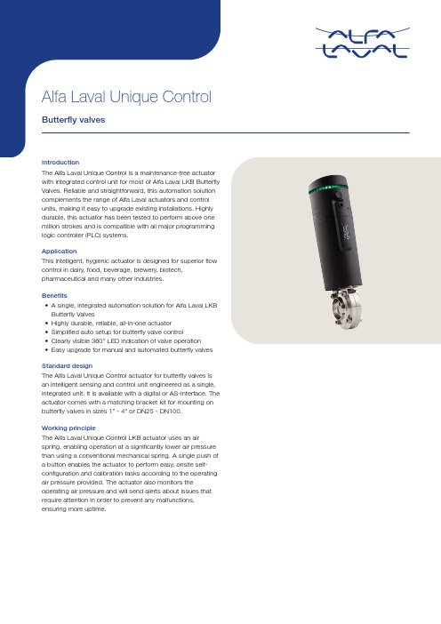
•Easy upgrade for manual and automated butterfly valvesStandard designThe Alfa Laval Unique Control actuator for butterfly valves is an intelligent sensing and control unit engineered as a single, integrated unit. It is available with a digital or AS-Interface. The actuator comes with a matching bracket kit for mounting on butterfly valves in sizes 1” - 4” or DN25 - DN100.Working principleThe Alfa Laval Unique Control LKB actuator uses an air spring, enabling operation at a significantly lower air pressure than using a conventional mechanical spring. A single push of a button enables the actuator to perform easy, onsite self-configuration and calibration tasks according to the operating air pressure provided. The actuator also monitors the operating air pressure and will send alerts about issues that require attention in order to prevent any malfunctions, ensuring more uptime.TECHNICAL DATAMin. air pressure:300 kPa (3 bar)Working temperature:See pd sheet for LKB/LKB-FAmbient temperature:-5°C to +60°CProtection class:IP66 and IP67Air consumption (liters free air):0.8 x p (bar)Interface:DigitalSupply voltage:24 VDC ± 10%Option 2:Interface:AS-Interface v2.1, 31 nodeSupply voltage:29.5V - 31.6 VDCSlave profile:7.F.F.FDefault slave address:0Option 3:Interface:AS-Interface v3.0, 62 nodeSupply voltage:29.5V - 31.6 VDCSlave profile:7.A.7.7Default slave address:0Feedback signal #1:De-energizied valveFeedback signal #2:Energizied valveFeedback signal #3:Pressure alertValve tolerance band:Auto setupPHYSICAL DATASteel parts: 1.4301 (304) and 1.4404 (316)Seals:NBRLKB-2:DN 25, 32, 40, 50, 65, 80 and 100Max. wire diameter: 1.0 mm2 (AWG 18)Air supply:300-800 kPa (3-8 bar)Type of solenoid:4/2-waysNumber of solenoids:1Manual hold override:YesPush-in fittings: 6 mm or 1/4"Air quality:Class 3,3,3 acc. DIN ISO 8573-1AvailabilityThe Unique Control is available with a digital or AS-Interface 31 and 62 node. Depending on the valve size, the matching bracket kit ordered together with the Unique Control allows it to be mounted on any butterfly valve size 1” through 4” (DN25 -DN100).OptionsBracket kit 1" to 4" (One kit for each valve size).Note! For further information: See also instruction manual ESE02126. Only to be mounted on LKB/LKB-F with welding endsElectrical connectionInternal connectionSolenoidSolenoid common Power supplySupply 24 VDC Supply 0 VDC PL output signalsSolenoid valvePL input signalsDe-Energized valve Energized valve Pressure Alarm Digital interface Sensor boardTerminal stripInternal connectionSolenoidSolenoid common Bus cableASI +ASI -S-interface 31/62 nodeSensor board Terminal stripAS-Interface bits assignmentDI0Feedback #1 De-Energized valve DI1Feedback #2 Energized valve DI2Feedback #3 NCDI3Feedback #4 pressure alarm DO0Out #1 NCDO1Out #2 Solenoid valve DO2Out #3 NC DO3Out #4 NCBasic DesignEA. Push and playB. Terminal stripC. Solenoid valveD. Manuel hold overrodeE. LED indicationsF . Gore venting membrane G. Push-in fittingsH. Cable gland entryBracket kitchangeable couplingsupporting 1” to 4” LKB valvesActuator performance46057669071048118Dimensions (mm)øB979797C111111111L263263263d81012Weight (kg) 1.6 1.6 1.6900615This document and its contents are subject to copyrights and other intellectual property rights owned by Alfa Laval AB (publ) or any of its affiliates (jointly “Alfa Laval”). No part of this document may be copied, re-produced or transmitted in any form or by any means, or for any purpose, without Alfa Laval’s prior express written permission. Information and services provided in this document are made as a benefit and service to the user, and no representations or warranties are made about the accuracy or suitability of this information and these services for any purpose. All rights are reserved.200002162-2-EN-GB© Alfa Laval AB How to contact Alfa LavalUp-to-date Alfa Laval contact details for all countries are always availableon our website at 。
阿尔法变频技术 ALPHA5000系列变频 器 说明书

前言前言首先感谢您选用深圳市阿尔法变频技术有限公司的ALPHA5000系列变频器。
ALPHA5000系列变频器是采用磁通矢量控制方式的变频器,低速额定转矩输出,超静音稳定运行,内置PID功能可以方便地实现PID闭环控制,先进的自动转矩补偿,控制方式多样,多达36种的完善保护及报警功能,多种参数在线监视及在线调整,内置RS-485通讯接口,操作灵活,能最大限度地满足用户的多种需求。
节能运行可以最大限度地提高电机功率因数和电机效率。
ALPHA5000系列变频器适用于绝大多数电机驱动领域,包括造纸、纺织、食品、水泥、印染、塑胶机械、冶金、钢铁等行业;作为调速装置负载适应性强,运行稳定、精度高,可靠性好。
可最大限度提高功率因数及效率,作为电气节能应用。
如在使用过程中还存在解决不了的困难,请联络本公司的各地经销商,或直接与本公司联系。
为用好本产品及确保使用者安全,在您使用之前,请详细阅读本用户手册,阅读完后请妥善保管,以备后用。
资料如有变动,恕不另行通知。
在安装、调试、使用变频器之前,为了您的人身安全,并有助于延长设备使用寿命,请您务必阅读本书安全规则及警告,以及贴于设备上的警示标志。
在使用时,也请您务必注意驱动机械的情况或一切有关安全的注意事项。
1前言2危险!u本设备带有危险电压,与警告不符的或违反本手册的操作可能带来生命危险和人身伤害。
只有相关专业人员,在熟悉了本手册的安全事项和安装操作之后,才能实际运行本设备。
u实施配线、检查等作业,必须关闭电源。
在本机印刷电路板上的充电指示灯熄灭前或在键盘显示熄灭后5分钟之内,请勿触摸机内电路板及任何零部件。
必须用仪表确认机内电容已放电完毕,方可实施机内作业,否则有触电的危险。
u绝不可将交流电源接至变频器输出端子U、V、W。
使用时,变频器的接地端子请依照IEC电气安全规程或其它类似标准,正确可靠接地。
警告!u未经授权的更改机内连线和使用非法厂商销售或推荐的附件,可能引起火灾、电击和人身伤害。
富士AC伺服系统FALDIC-W系列用户手册 参数(1)

/参数39号编号名称设定范围初始值变更39零速钳位电平0.0~500.0[r/min](0.1刻度)0.0一直设定零速钳位的伺服电机的旋转速度。
在输入位置控制及速度控制的模拟量速度命令时有效。
如果模拟量速度命令(Vref)输入端子的速度命令值低于零速钳位电平,则对旋转速度进行零速钳位。
防止模拟量速度命令输入值在零附近漂移。
旋转速度[r/min]模拟量速度命令输入值(Vref)[r/min]参数39零速钳位电平当模拟电压处于设定值附近时,「零⇔设定值」与命令不稳定,有时导致电机轴不稳定。
控制系统的设定按编号记载控制系统设定参数的设定内容。
■控制方框图表示FALDIC-W 系列的控制方框图。
减振控制(兼用)(兼用)输入指令控制序列端子反共振频率0 CONTn反共振频率选择0/1 (分配号9,10)注)在P 的后面记载的数值为参数号。
例)P10→参数10号命令跟踪控制选择自动提前增益命令跟 踪控制反共振频率1反共振频率2 反共振频率3 输入脉冲串CONTn命令脉冲α选择0/1 (分配号12,13)CONTn禁止命令脉冲 (分配号: 11)前馈前馈过滤器时间常数输入脉冲串形式命令脉冲补偿S 字时 间常数位置调节器增益输入速度命令Vref模拟量 命令补偿 模拟量 命令增益脉冲发生软启动S 字时 间常数手动进行速度1~3CONTn 多段速度1/2 (分配号: 17,18) CONTn 加减速时间选择 (分配号: 19)输入转矩命令 (Vref 兼用)模拟量 命令补偿 模拟量命令增益 转矩设定过滤器分频电路分频输出端子※若接通禁止命令脉冲,则可以手动运行(位置JOG)。
切换控制模式:P09=3(位置⇔速度)时CONTn切换控制模式(分配号: 14)切换控制模式:P09=4(位置⇔转矩)或5(速度⇔转矩)时CONTn切换控制模式(分配号: 14)速度设定过滤器电流控制陷波滤波器转矩过滤器时间常数P1控制惯量推断负荷惯量比自动调整调整模式自动调谐增益P05(调整模式)在「0: 自动调整」或「1: 半自动调整」下时,注)在P的后面记载的数值为参数编号。
富士伺服系统 faldic-w series 说明书
报警复位
报警记录初始化
参数初始化
自动补偿调整
Z相位置调整
自动调谐增益
调试简单
模式运行
型号说明
&YQMBOBUJPOPG.PEFM$PEFT
伺服放大器
表示 3:$
表示
NNEJW SNJOEJW
手臂 振动 实际速度
NNEJW SNJOEJW
手臂 振动 实际速度
Feature 2
参数的 一体化管理
无减振控制功能
有减振控制功能
用上位控制器实现参数的一体化管理
˙标准配备34个通信接口 上位控制器与各伺服放大器之间采用RS-485通信。 上位控制器可以一体化管理伺服放大器的参数。
利用简易调试功能来实现「使用方便性」
符合RoHS标准的「环保型产品」 3种不同的额定转速的伺服电机,使应用领域更加广泛。
W i d e 容量范围 Range
L8 L8 L8 L8 L8 L8
小 惯 量 系 列( G Y S 电 机 )额定转速3 0 0 0 r / m i n
Feature 1
减振控制 功能
最大限度抑制机械振动 本公司独创的减振控制功能(正在申请专利)
˙为解决机器人手臂前端等的振动问题,标准配备「减振控制功能」。
标准配备本公司独创的「减振控制功能」,可以减少低刚性机械的振动,实现机械的高节 拍运行。
移动方向 根据激光变位计测量的振动波形
移动方向 根据激光变位计测量的振动波形
采用!% 脉冲的高分辨率编 码器。 提高了伺服电机旋转分辨率,实 现低速平稳的机械运行。
伺服系统 分析功能
利用我公司的调试软件对机械固 有的「共振频率」等进行分析, 可以有效利用「减振控制功能」、 「陷波滤波器」等功能。
Alpha500使用说明书(PDF文件)

Alpha 500系列说明书一.注意事项一.注意事项a500系统在使用上非常简单,但在操作时必须注意其安全性,唯有在正确的操作 下,才能增加工作效益,提升生产力。
※以下几点事项,操作者必须严格遵守:1. 请勿任意更改发射机及接收机密码。
2. 经常检查发射机外壳及按键,发现破损应立即更换。
3. 随时注意并检查发射机电压,如没电压或电压不足请立即更换二颗碱性电池(注意电池极性)。
4. 工作前,务必检查紧急停止键是否正常。
5. 任何不正常情况发生时,不可先关闭电源,应立即按紧急停止键。
6. 在300米范围内,避免使用同一频道之遥控器。
7. 在电压不足或视线不佳的情况下,不得使用遥控器。
8. 使用者不得任意变更控制,调整及使用方法。
9. 维修或有调整需求应由具有发射机维修专长之技术人员执行直接监督及负责。
10.使用者不得任意置换零件(如电晶体、振荡器....等)。
11.低功率及射频管理规则:⑴ 依第七条至第九条型式审认或审验合格之低功率射频电机,厂商或使用人不得擅自改变频率、加大功率,外接十四条规定以外之天线或变更原设计之 功能。
⑵ 低功率射频电机之使用不得干扰合法通信,经发现有干扰现象时应停止,并改善至无干扰时方得继续使用。
低功率射频电机需忍受合法通信或工业、 科学及医疗用,辐射性电机之干扰。
⑶ 低功率射频电机之产销厂商或使用人违反擅自使用或变更无线频率、电功率者,依电信法相关条文之规定处罚。
“ 0 ”抑制“ 1 ”不抑制“ 0 ”抑制“ 1 ”不抑制“ 0 ”一般动作“ 1 ”自保持“ 0 ”抑制“ 1 ”不抑制“ 0 ”抑制“0”双继电器动作“ 00 ”一般动作“10”启动3速功能“ 0 ”抑制“ 0 ”一般动作“ 1 ”自保持“ 0 ”一般动作“ 1 ”自保持“ 1 ”不抑制“ 0 ”一般动作“ 1 ”自保持“ 0 ”一般动作“ 1 ”自保持“ 0 ”一般动作“ 1 ”自保持“1”单继电器动作“ 01 ”自保持“ 0 ”一般动作“ 1 ”自保持“0”双继电器动作“1”单继电器动作“ 0 ”一般动作“0”双继电器动作“1”单继电器动作“ 1 ”不抑制“ 0 ”一般动作“ 1 ”自保持“ 0 ”一般动作“ 1 ”自保持“ 00 ”一般动作“ 01 ”自保持“10”启动3速功能“ 0 ”一般动作“ 1 ”自保持“ 0 ”一般动作“ 1 ”自保持Alpha 580 指拨开关功能板(按键排列请参考第4-5页)指拨位置 注一:不可设定,需强制设定为“ 0 ” ※以上出厂设定值均为“ 0 ”DIP2- 2&39Alpha580C-1&RES 1RES 2Alpha580A/B/C/D/E 功能扩充DIP2-7DIP2-810 1&2(2速) 1&2(2速)7&87 Alpha 580E 98Alpha 580C-2Alpha 580D DIP2-2DIP2-3DIP2-4DIP2- 5&6DIP2-4DIP2-2,3,4DIP2-1DIP2-17&89&10107&81&2(2速)Alpha 580B 987Alpha 580A9DIP2-2DIP2-4DIP2-1DIP2-3DIP2-3DIP2-4DIP2-5DIP2-6DIP2-15&67&8按 键机 型1&2DIP2-1DIP2-23&4 出厂设定值为“0”(注一)DIP2-2拨至“ 1 ”才有效用DIP2-2拨至“ 1 ”才有效用于Alpha580A/B/C/D/E 之标准下并无此功能,需特别另外订做。
伺服电机简介

专用控制器
ALPHA5
Smart
切割绝缘子外形的机器。 切割绝缘子外形的机器。 根据削割部分的尺寸在定位用途上使用。 根据削割部分的尺寸在定位用途上使用。
Jde085-00003
应用例
在金属切边机!
☆通过密间隔运行模式的设定,可以适 通过密间隔运行模式的设定, 应对周期时间要求严格的动作操作。 应对周期时间要求严格的动作操作。 ☆通过与专用控制器的结合可以进行定 位运行。 位运行。
外形尺寸
外形尺寸缩小! 外形尺寸缩小!
165 165
当然、可以紧密安装!
FALDIC-W
160 160
1.5kW比較
40
比W系列 缩小5mm
70
比W系列缩小 15mm (at1kW)
50~400W
500W~1.5kW
(1.3kW除外)
ALPHA5 Smart
Jde085-00003
界面
操作 按键 4个 MODE、SET、△、▽ 主电源 PC Loader USB线
Jde085-00003
Smart调整 调整
Jde085-00003
Smart调整 调整
Jde085-00003
Smart设计 设计
高性能
お手軽!PTP 位置決め
定位 功能
原来的伺服系统
紧凑型
Jde085-00003
Smart设计 设计
Jde085-00003
Smart设计 设计
Jde085-00003
FALDIC-W
ALPHA5
ALPHA5 Smart
Jde085-00003
应用例
富士AC伺服系统FALDIC-W系列用户手册 参数(2)

/参数19号 编号 名称 设定范围初始值 变更 19输出脉冲数16~32768[脉冲](1刻度)2048电源设定伺服电机每转一周时,分频输出的脉冲数。
输出形式为90度相位差2路信号。
伺服电机的输出轴为正转,输出B 相前进信号。
通过设定转动方向切换(参数4号)可以切换相的顺序。
・参数4号的设定值=1或 2时,逆时针旋转时B 相前进 ・参数4号的设定值=1或 2时,逆时针旋转时A 相前进可以设定伺服放大器的分频输出端子[FA],[*FA],[FB],[*FB]端子的输出脉冲数。
A 相及B 相信号为50[%占空比]。
Z 相信号每转一周输出1个脉冲。
输出幅度取决于输出脉冲数。
A 相信号与Z 相信号是同步的。
输出频率请在500[kHz]以下使用。
伺服放大器对输出频率无限制。
不能指定伺服电机的输出轴的位置与Z 相位置的关系。
B 相[FB] B 相[*FB] Z 相[*FZ]A 相[*FA] A 相[FA] Z 相[FZ] 脉冲幅度: t 11≥1μs(相当500kH Z )在输出脉冲数设定为3000[脉冲/周]状态下,以5000[r/min] 旋转时的输出脉冲数3000[脉冲/周]60×5000[r/min]=250000[Hz]若在最大值32768[脉冲/周]状态下变为5000[r/min],则超过2.7[MHz]。
提示/编号 名称 设定范围初始值 变更 20Z 相补偿0~65535[X2脉冲](1刻度)电源变更Z 相的输出位置时设定。
在CCW(逆时针)方向,只有参数20号设定的脉冲量偏离Z 相的输出位置。
该参数与转动方向切换(参数4号)无关。
在Z 旋转时,在CCW(逆时针)方向出现Z 相的输出位置偏移。
■Z 相的输出位置 ・Z 相补偿值为[0]时 ・Z 相补偿值为[16384]时※键的位置不是Z 相。
用于说明时,暂时将键位置设为Z 相。
■相关可以利用触摸面板的试运行模式调整Z 相位置,以便让当前位置变为Z 相输出位置。
富士AC伺服系统FALDIC-W系列用户手册

4.请不要接错编码器的端子的顺序。 否则编码器和伺服放大器会破损。
强制
·地线是用于防止万一发生触电事故的。 为安全起见,务必请安装地线。
本产品不是以用于涉及人身生命的机器及系统为目的而设计和制造的。如果计划将其 用于航空控制设备、交通管制设备、宇航设备、核能控制设备或医用设备及其系统等 特殊用途时,请与本公司营业窗口接洽。 如果将该产品用于其故障有可能危及人身性命或导致重大损失的设备上时,请在该设 备上安装适当的安全装置。
前言
本手册是 "富士 AC 伺服系统 FALDIC-W 系列用户手册"。 用户手册由 1 册构成,记载产品的所有使用说明。
4.发生报警时,请排除原因,确保安全后,将报警复位后再运行。 否则有可能受伤。
5. 瞬间停电后再来电时电机有可能突然再启动,因此请不要靠近设备。(请在机 械设计时考虑,如何保证再启动时人身安全) 否则有可能受伤。
6.请确认电源规格正常。 否则有可能导致火灾、故障和受伤。
禁止
·装入伺服电机中的制动器是用于自保的,故请不要用于一般的制动。 否则有可能发生故障、受伤。
在各种设备的包装内备有以下资料。
设备
资料名称
伺服放大器
使用说明书 富士 AC 伺服 FALDIC-W 系列 伺服放大器 (RYC□□□D(C,B)3-△△△2)
伺服电机
使用说明书 富士 AC 伺服电机(GYS/GYG 系列)
资料编号 INR-SI47-0853
ING-SI47-0863
该手册的相关产品的型号如下。
ALPHA5300系列张力控制专用变频器 说明书

ALPHA5300系列张力控制专用变频器为卷绕专用变频器,ALPHA5300基于ALPHA 5000系列,针对卷绕行业的要求进行功能和性能改进以代替力矩电机。
除以下专用参数之外,其余功能与ALPHA 5000通用型一致。
因此必须结合我公司ALPHA 5000系列通用变频器说明书使用。
一,功能参数简表P6:张力控制组功能代码参数名称设定范围出厂设定更改MODBUS地址基本参数P6.00 张力控制模式0:无效1:开环转矩张力控制模式12:开环转矩张力控制模式23:闭环张力速度控制模式0 ×0700P6.01 卷取模式0:收卷1:放卷0 ○0701P6.02 机械传动比0.01~300.00 1.00 ○0702 张力设定P6.03 张力设定源0:P6.04数字设定1:AI1设定2:AI2设定3:PULSE脉冲输入设定4:通讯设定0 ×0703P6.04 张力设定0~30000N 0 ×0704 P6.05 最大张力0~30000N 0 ×0705 P6.06 零速张力提升0.0~50.0% 0.0% ○0706 P6.07 零速阀值0~20%(最大频率)0% ○0707 张力锥度P6.08 张力锥度源选择0:P6.09设定1:AI1设定0 ○0708代码参数名称设定范围设定改地址2:AI2设定3:PULSE脉冲输入设定4:通讯设定P6.09 张力锥度0.0~100.0% 0.0% ○0709 P6.10 锥度补偿修正量0~9999mm 0mm ○070AP6.11 闭环张力控制张力锥度起效选择0:锥度有效1:锥度无效0 ○070BP6.12 对外锥度控制最大输出数字设定0.0~100.0% 100.0% ○070C卷径计算P6.13 卷径计算方法选择0:不计算1:线速度计算2:通过厚度累计计算3:AI1输入4:AI2输入5:PULSE脉冲输入6:通讯1 ×070DP6.14 最大卷径1~9999mm 500mm ×070E P6.15 卷轴直径1~9999mm 100mm ×070FP6.16 初始卷径源0:P6.17-P6.19设定1:AI1设定2:AI2设定0 ×0710P6.17 初始卷径1 1~9999mm 100mm ×0711 P6.18 初始卷径2 1~9999mm 100mm ×0712 P6.19 初始卷径3 1~9999mm 100mm ×0713 P6.20 卷径滤波时间0.0~100.0s 1.0s ○0714 P6.21 卷径当前值1~9999mm 1 mm * 0715 P6.22 每圈脉冲数1~60000 1 ○0716 P6.23 每层圈数1~9999 1 ○0717代码参数名称设定范围设定改地址P6.24 计圈信号选择0:X1~X8端子1:PG测速0 ×0718P6.25 材料厚度设定源0:数字设定1:AI1设定2:AI2设定0 ○0719P6.26 材料厚度0 0.01~99.99 mm 1.00mm ○071A P6.27 材料厚度1 0.01~99.99 mm 1.00mm ○071B P6.28 材料厚度2 0.01~99.99 mm 0.01mm ○071C P6.29 材料厚度3 0.01~99.99 mm 0.01mm ○071D P6.30 最大厚度0.01~99.99 mm 0.01mm ○071EP6.31 线速度输入源0:无输入1:AI12:AI23:PULSE脉冲输入4:通讯设定1 ○071FP6.32 最大线速度0.1~6500.0 m/Min 400.0m/Min○0720P6.33 卷径计算最低线速度0.1~6500.0 m/Min0.5m/min○0721P6.34 线速度实际值0.1~6500.0 m/Min0.1m/Min* 0722补偿参数P6.35 保留 5.0~80.0% 20.0% ○0723P6.36 卷径计算厚度累计方向0~1 0 ×0724P6.37 机械惯量补偿系数0:无操作1:开始辨识自学习结束后动恢复到00 ○0725P6.38 材料惯量补偿系数0~9999 0 ○0726代码参数名称设定范围设定改地址P6.39 材料密度0~9999 0Kg/m^3 ○0727 P6.40 材料宽度0~60000Kg/m^3 0mm ○0728 P6.41 摩擦补偿系数0~60000mm 0.0% ○0729 P6.42 高速力矩补偿增益0.0~50.0% 100.0% ○072AP6.43 补偿依据0:频率1:线速度0 ○072BP6.44 高速力矩补偿投入点0.0~100.0% 80.0% ○072C 断料处理P6.45 断料检测方式0:不检测1:根据断料接近开关信号2:根据PID反馈(摆杆信号)0 ○072DP6.46 断料自动检测最低频率0.00~50.00Hz 10.00Hz ○072EP6.47 断料检测范围0.00~10.00V 1.00V ○072FP6.48 断料自动检测判断延时0.1~60.0s 2.0s ○0730第二组PIDP6.49 比例增益P2 0.0~100.0 20.0 ○0731 P6.50 积分时间I2 0.01~10.00s 2.00s ○0732 P6.51 微分时间D2 0.00~10.00s 0.00s ○0733P6.52 PID参数自动调整依据0:只用第一组PID参数1:根据卷径调节2:根据运行频率调节3:根据线速度调节4: 端子切换0 ○0734P6.53 张力闭环控制调节限幅0.0~100.0% 50.0% ○0735P6.54 张力闭环控制调节限0.0~100.0% 0.0% ○0736代码参数名称设定范围设定改地址幅偏置自动换卷参数预驱动处理P6.55 预驱动转矩限幅选择0:PD.05设定1:根据张力设定限幅0 ○0737P6.56 预驱动转矩增益50.0~150.0% 100.0% ○0738 P6.57 预驱动速度增益50.0~150.0% 100.0% ○0739 P6.58 预驱动卷径计算选择0:计算1:停止计算1 ○073AP6.59 预驱动结束后卷径计算停止延迟时间0.0~10.0s 5.0s ○073B P6.60 张力提升比例0.0~200.0% 50.0% ○073C 机械抱闸动作参数P6.61 刹车信号输出频率0.00~50.00Hz 1.50Hz ○073D P6.62 刹车时间0.1~100.0s 6.0s ○073E P8:力矩控制组功能代码参数名称设定范围出厂设定更改MODBUS地址P8.00 控制模式0:普通模式1:力矩模式1 ×0900P8.01 卷取模式0:收卷1:放卷0 ×0901P8.02 转矩设定源0:数字设定1:AI12:AI20 ○0902P8.03 转矩数字设定0.0~200.0% 55.0% ○0903P8.04 模拟量10v对应额定转矩百分比50.0~200.0% 100.0% ○0904P8.05 额定转矩加速时间0.01~120.0s 0.05 ○0905代码参数名称设定范围设定改地址P8.06 额定转矩减速时间0.01~120.0s 0.08 ○0906 P8.07 转矩滤波时间0.00~2.55s 0.50 ○0907 P8.08 转矩偏差0.0~25.5% 1.0 ○0908 P8.09 零速转矩提升0.00~50.00% 5.50% ○0909 P8.10 转矩修正系数0.0~100.0% 50.0% ○090A P8.11 转矩修正截至点0.0~50.00Hz 10.00 ○090BP3组:端子控制组功能代码参数名称设定范围出厂设定更改MODBUS地址P3.00 端子作用方式0:闭合有效1:开路有效(常开/常闭不受此限制)0 ×0400P3.01 X1端子功能定义0:NULL 无定义1:FWD正向运行2:REV 反向运行3:RUN运行4:F/R运转方向5:HLD自保持选择6:RST 复位7:FC设定频率选择8:FJOG 正向点动9:RJOG 反向点动10:UP上升11:DOWN下降12:UP/DOWN清013:FRE 自由停车14:强迫停机(按减速时间4)15:停机直流制动3 ×0401代码名称设定范围设定改地址P3.02 X2端子功能定义16:加减速禁止17:变频器运行禁止18:S1 多段速度119:S2多段速度220:S3多段速度321:S4多段速度422:S5多段速度523:S6多段速度624:S7多段速度725:保留26:SS1多段速度27:SS2多段速度28:SS3多段速度29:保留30:T1加减速时间131:T2加减速时间232:T3加减速时间333:T4加减速时间434:TT1加减速时间35:TT2加减速时间36:保留37:EH0外部故障常开38:EH1外部故障常闭39:EI0外部中断常开40:EI1外部中断常闭41:保留42:保留43:保留4 ×0402P3.03 X3端子功能定义48 ×0403代码名称设定范围设定改地址P3.04 X4端子功能定义44: 保留45: 保留46: 保留47:PID投入48:力矩模式无效49:定时驱动输入50:计数器触发信号输入51:计数器清零复位52:保留 53:保留54:卷径复位55:初始卷径选择端子156:初始卷径选择端子257:预驱动输入端子58:计圈信号59:转矩记忆60:记忆转矩使能61:收放卷切换62:卷径计算停止63:厚度选择端子164:厚度选择端子265:张力控制禁止端子66:转矩提升端子67:两套PID参数切换68:保留69:保留70:PUL 脉冲输入(如有2路输入,以X7为准)71:单相测速输入(如有2路输入,以X7为准)72 ×0404P3.05 X5端子功能定义73 ×0405代码名称设定范围设定改地址72:测速输入SM1(仅对X7设定)73:测速输入SM2(仅对X8设定)P3.06 保留保留0 - 0406 P3.07 保留保留0 - 0407 P3.08 保留保留0 - 0408P3.09 运转模式设定0:两线式运转模式11:两线式运转模式22:三线式运转模式1-自保持功能(附加X1~X5中任意一端子)3:三线式运转模式2-自保持功能(附加X1~X5中任意一端子)0 ×0409P3.10 端子UP/DOWN速率0.01~99.99Hz/s1.00Hz/s○040AP3.11 UP/DOWN给定值幅值0.00~上限频率10.00Hz×040BP3.12 数字频率UP/DOWN存储选择0:接到STOP,UP/DOWN给定值复位为01:接到STOP,UP/DOWN给定值不复位为0,掉电不保存;2:接到STOP,UP/DOWN给定值不复位为0,掉电保存; P0.01设定为1时,P0.00在线调整掉电保存1 ×040C代码名称设定范围设定改地址P3.13 D0端子功能定义0:NULL 无定义1: RUN 运行2: FAR 频率到达3: FDT 频率检测 14: FDTH上限频率到达5: FDTL下限频率到达6:保留7:变频器零速运行中8:保留9:保留10:变频器运行准备完成(RDY)11:自由停车12: 自动重新启动13: 定时到达14: 计数到达输出15: 设定运行时间到达16:转矩到达检测17: CL 限流动作18: 过压失速19:变频器故障20: 外部故障停机(EXT)21:Uu1 欠压停止22:CE通讯告警23:过载检出信号(OLP)注124:模拟信号1异常25: 模拟信号2异常注226: STEP程序运行步数(仅对0 ×040DP3.14 保留 1 ×040E代码名称设定范围设定改地址P3.15 保留Do\Y1\Y2有效,要求同时设定26)27:故障类型输出(仅对DO\Y1\Y2有效,要求同时设定27)28:保留29:休眠中30:零速31:断料检测输出32:抱闸信号输出2 ×040FP3.16 继电器1(TA/TB/TC)输出功能选择19 ×0410P3.17 定长到达端子输出保持时间0.0~3.0s 1.0s ×0411P3.18 频率到达FAR检测宽度0.00~10.00Hz2.50Hz○0412P3.19 FDT电平0.00~650.0Hz 50.00Hz○0413P3.20 FDT滞后0.00~10.00Hz 1.00Hz○0414P3.21 上限频率到达端子输出延迟时间0.0~100.0s 0.0s ○0415P3.22 下限频率到达端子输出延迟时间0.0~100.0s 0.0s ○0416P3.23 转矩检测设定值0.0~200.0% 100.0%○0417P3.24 计数值到达给定0~9999 0 ○0418 P3.25 定时到达给定0.0~6553 0.0 ○0419代码名称设定范围设定改地址P3.26 设定运行时间0~65530h 65530h×041APC:显示控制功能代码参数名称设定范围出厂设定更改MODBUS地址PC.01 输出频率(Hz)(补偿前)0:不显示 1:显示 1 ○0D01PC.02 输出频率(Hz)(实际)0:不显示 1:显示0 ○0D02 PC.03 输出电流(A)0:不显示 1:显示 1 ○0D03 PC.04 设定频率(Hz闪烁)0:不显示 1:显示 1 ○0D04 PC.05 运行转速(r/min)0:不显示 1:显示0 ○0D05 PC.06 设定转速(r/min闪烁)0:不显示 1:显示0 ○0D06 PC.07 运行线速度(m/s)0:不显示 1:显示0 ○0D07 PC.08 设定线速度(m/s 闪烁)0:不显示 1:显示0 ○0D08 PC.09 当前卷径0:不显示 1:显示0 ○0D09 PC.10 输出转矩(%)0:不显示 1:显示0 ○0D0A PC.11 输出电压(V)0:不显示 1:显示 1 ○0D0B PC.12 母线电压(V)0:不显示 1:显示0 ○0D0C PC.13 AI1(V)0:不显示 1:显示 1 ○0D0D PC.14 AI2(V)0:不显示 1:显示0 ○0D0E PC.15 模拟PID反馈0:不显示 1:显示0 ○0D0F PC.16 模拟PID设定0:不显示 1:显示0 ○0D10 PC.17 电机转向指示0:不显示 1:显示0 ○0D11 PC.18 端子状态(无单位)0:不显示 1:显示 1 ○0D12 PC.19 实际长度0:不显示 1:显示0 ○0D13 PC.20 开机显示选择1~19 1 ○0D14二,参数详细说明控制模式选择部分:P6.00 张力控制模式设定范围:0-3【0】0:无效1:开环转矩张力控制模式12:开环转矩张力控制模式2 3:闭环张力速度控制模式说明:u0:无效。
弗达尔(Fadal)主机器人维护手册部分内容说明书
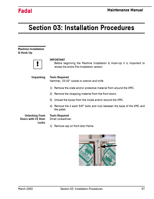
Section 03: Installation Procedures Machine Installation& Hook-UpIMPORTANTBefore beginning the Machine Installation & Hook-Up it is important toreview the entire Pre-Installation section.Unpacking Tools RequiredHammer, 15/16” socket or wrench and knife1)Remove the crate and/or protective material from around the VMC.2)Remove the strapping material from the front doors.3)Unload the boxes from the inside and/or around the VMC.4)Remove the 4 each 5/8” bolts and nuts between the base of the VMC andthe pallet.Unlocking Front Doors with CE DoorLocks Tools RequiredSmall screwdriver.1)Remove cap on front door frame.!2)Release the screw.3)Turn to override door lock.Moving the VMC:Fork Lift (See Figure 3-2).Tools Required5/32” hex bit socket or Allen wrench.IMPORTANTThe head and the counterweight must be secured before lifting the VMC.Since the TRM doesn’t have a counterweight, only secure the head on theTRM.1)Remove the 4 each (per panel) 1/4-20 cap bolts from the access panel ifnot already removed.2)Install the fork lift bars through the openings in the base casting. Fork liftbars may be obtained from FADAL if none are available.3)FORK LIFT from the front of VMC.Note: VMCs EMC, 5, 10, 15, and 15XT have fork lift access supports as part of the base. On the TRM it is recommended that the machine is picked up from the front or the back.!IMPORTANTFor the 6535 use a forklift with a 30,000 plus lifting capacityMoving the VMC:Crane (See Figure 3-2).Tools Required1/4” and 9/16” hex bit socket or Allen wrench.IMPORTANTThe head and the counterweight MUST be secured before lifting the VMC.Since the TRM doesn’t have a counterweight, only secure the head on the TRM.VMCs 5, 10, 15, and 15XT are NOT intended to be lifted by a crane.1)Remove the 1/4-20 cap bolts to the axis scale cover, if installed.2)Remove the 5/16-18 cap bolts securing the front Teleflex cover to thesaddle.3)Slide the Teleflex cover toward the front of the VMC.4)Remove the 2 each 1-8 (1.5-6 for the 6535) set screws in the front of thebase casting.5)STANDARD SHEETMETAL: Install the 2 each 1-8 eye bolts. Place the 1 1/4” steel bar through the top rear hole in the column side. (See Figure 3-2).Use a properly rated lifting strap around bar and through eyebolts for lifting.SLANT SHEETMETAL: Install the 2 each 1-8 eye bolts (1.5-6 eye bolts for the 6535). Remove upper cover from back of column. Place two 1 1/4”steel bars through the two top holes in the column rear. Use a properly rated lifting strap around bar and through eyebolts for lifting.!Remove !Lifting Bar HolesFigure 3-1 Slant Sheetmetal DetailsPlacing the VMC1)Place the leveling pads (countersink side up) under the leveling bolts. Be sure leveling bolts go into countersink on leveling pads.Note: Use leveling pad (SHP-0002) (PLC-0063 for slant sheet metal machines, or machines equipped with the HydroSweep option) for placing themachine. Any other pad may cause damage to the machine.2)Remove the fork lift bars or the eye bolts and the steel bar from the column.3)At this point the VMC is ready for power and air connections.Figure 3-2Moving the VMCAir Supply IMPORTANTAIR PRESSURE REQUIRED: 120 psi before regulator, 80 psi after regulator,15 scfm (standard cubic feet per minute) momentary.1)Connect the 3/8” air hose to the VMC.2)Check the pressure gauge for 120 psi and adjust the regulator on the VMC if necessary.3)Check for air leaks at the fitting and around the air regulator.4)It is important that the air compressor turns on when the pressure drops to approximately 120 PSI. This assures the VMC a constant 80 PSI.Power CheckWARNINGDo NOT power on the VMC before completing this section.Tools RequiredFluke DMM, screwdriver or Wago tool 210-141(ST-26), 5/16” hex bit socket and 3/4” open or box wrench.Verify the Main Power Fuses1)With the main disconnect switch in the off (down) position, open the cover to the main disconnect box.2)Measure and record the incoming voltage across the terminal block of the main disconnect. (See Figure 3-3).Figure 3-3 Main Disconnect Terminal Block3)Using table B- 3 in Appendix B (MAIN POWER FUSES), verify that the fuses match the voltage and machine type, e.g. 4020HT, 240V, 60HZ, 3Ø = 45A.!!Verify the MOV Surge Suppressor Board1)Locate the MOV Surge Suppressor Board (see figure 3-4).Figure 3-4 MOV Surge Suppressor Board2)Find the part number on the board.a.If your incoming voltage is under 250 VAC, then an 1170-0 (PCB-0145)should be installed.b.If your incoming voltage is over 250 VAC, then an 1170-1 (PCB-0146)should be installed.3)Identify the jumper and AC input locations. Use figures 3-10 through 3-14for three phase and single phase transformers.a.Where are the jumpers located?b.Where are the AC inputs (L1, L2, L3) located?4)With the jumper and AC input locations, locate the voltage setting of thetransformer using the table in either Figure 3-10 (3 phase) or Figure 3-11(single phase).EXAMPLE:Jumper (Step 6a)AC Input (Step 6b)=Voltage Setting 3-68=240VACFigure 3-5Figure 3-11Figure 3-13Figure 3-14Figure 3-163)Subtract step (A3.2.6-7) from step (A3.2.6-2).EXAMPLE:measure voltage=240 L1-L2245 L1-L3242 L2-L3voltage setting=240 A240 B240 Cdifference=052a.If the difference is less then 10, continue.b.If the difference is greater than 10, adjust the voltage settings usingeither figure 9 (3 phase) or figure 10 (single phase) to match the mea-sured voltage.The VMC is Ready for the Initial Power on Procedure9)Move the main disconnect switch to the ON (up) position. DO NOT PRESSTHE GREEN CNC POWER BUTTON.10)Measure the voltage at the transformers secondary between A12-B12,A12-C12, B12-C12.11)For single phase measure across A8-C8. The voltage should be between230-240 VAC, correct if necessary.12)Push the EMERGENCY STOP switch to disable the axes, then push the CNCPOWER button.13)Check the voltages on the D.C. power supply, i.e. 5, + 12, -12 VDC.14)Reset the EMERGENCY STOP switch.15)Unbolt and remove the support between the table and the head.16)Unbolt and remove the counterweight bars from the column, located next tothe main disconnect box.17)Jog the axis to the cold start indicators and cold start the VMC. Transformer Tapping1)With the machine main power switch turned OFF, verify that the chart onthe door of the cabinet is the one for the transformer in the machine.2)Measure the input voltage to the machine on the chart (Measure leg to legthe input power lines to the machine.).3)Next to the voltage on the chart will be a “jumper” number such as 3-6 anda “AC Input” number such as 7.4)Each phase has a group of terminals such as A3 to A8 for phase 1 and B3to B8 for phase 2. Place a jumper between the two terminals listed on the chart for each phase. Using the same example place jumper from A3 to A6 for phase 1, B3 to B6 for phase 2 and one from C3 to C6 for phase 3.5)Place the input tap wire in the proper terminal, as in example A7 for phase1, B7 for phase 2 and C7 for phase 3.6)Turn ON the main power switch.7)Measure the input voltage to the spindle drive, usually labeled L1, L2 & L3,leg to leg. Should be about 230 VAC with the range being from 220 to 240 VAC. If the difference between 230 and the measured voltage is greater then ten (10) volts then power down. If the voltage is too high then select the next higher voltage on the chart and change the jumper and / or input tap and recheck. If the voltage is too low then select the next lower voltage and change and check.Note: It is acceptable to have the legs tapped differently by one voltage tap position. There should be no more than one position.Single Phase Input Power The Fadal VMC line is designed for three phase input power. However, three-phase power is not always available. If this is the case, Fadal offers a single-phase input power option. All Fadal machines are capable of operating on single-phase line input. The torque ratings will be at 60% of the published performance. The rapid traverse rate is reduced to not more than 700 IPM for machines with higher speed capability. This is because as the DC bus capacitors are drained and the bus voltage drops, the single-phase input can not recharge the capacitors as fast as the three-phase. Lower bus voltage equals lower speed and more current. Single-phase requires 73% more current to maintain the same performance (square root of 3). The main limitation is the spindle drive. It will not draw more than its rated current. The current rise is steeper in single-phase and will therefore trip sooner.Fadal does not recommend single-phase power for the High torque or the 6535, 6030 and 8030 machines and cannot be used with VHT. This option can be ordered on a new machine and can be installed in the field. Some wiring changes are also necessary. Please see the single-phase transformer charts and wiring instructions.Phase Converter Rotary The Normal Fadal VMC requires three phase-input power. The machines are also configured in a single-phase power configuration when requested. Some customers prefer to use rotary phase converters, however Fadal does not recommend the use of rotary phase converters.Rotary phase converters input single-phase 208 to 230 VAC and output three phase 230 VAC. For a VMC close to a 5% voltage balance between legs would be desired, in reference to the voltage differences of each phase. Most CNC machines would require the output power to be 1-1/2 to 2 times larger than the spindle motor (for a Fadal output must be at or higher than the minimum of the required input; see specifications). A Voltage Stabilizer may also be required. The stabilizer’s function is to maintain a consistent voltage level of the three phases during light or no load conditions.Transformer Sensor An improvement to transformer design has been developed and it can be retrofitted to existing machines originally fitted with T820, T821, or T822transformers. This improvement is designed to interrupt the Emergency Stopcircuit when the machine is used beyond its designed peak performance for anextended period of time, and transformer temperature approaches its ratedlimits.Figure 3-17 Transformer sensor kitTo determine if the machine has this circuit, look on the left side of thetransformer connector rail for a mechanical relay. If the transformer sensorcircuit is installed and an Emergency Stop occurs, check the mechanical relay.If the relay is activated (LED lit) then this circuit is not involved but if the relay isnot activated then the transformer is overheated. In this case power down themachine and allow the transformer to cool. If the condition persists, then thereis a problem that requires investigation.Leveling Leveling is an important first step in setting up the VMC. All calibration andsquareness performed on the assembly line is done with the machine leveled.It is important to follow the sequence below precisely to ensure proper results.Tools RequiredPrecision Level, such as the Starrett 12”, P/N 199ZIMPORTANTVerify that the scale reads the same when rotated 180 degrees.If using a flashlight to see the bubble, do not place the flashlight on thelevel, as it will warm the bubble and give an incorrect reading.For All VMCs 1)The VMC should be positioned on one solid concrete slab (see PRE-INSTALLATION section). Do not straddle any cracks or seams.2)Center the leveling pads under the leveling screws.Note: Use leveling pad SHP-0002 (PLC-0063 for slant sheet metal machines,or machines equipped with the HydroSweep option) for placing themachine.3)Level the VMC as close as possible to the leveling pads. The levelingscrews should be extended as little as possible to reduce vibration throughthe sheet metal.IMPORTANTMake sure that machines with the chip conveyor option are raised highenough so that the chip conveyor tank fits under the sheet metal of theVMC. See section 13 for more information on installing the chip conveyor.4)Verify the Cold Start indicators, then cold start the VMC.5)Clean the level with alcohol.Box Way VMCs 1)Jog the Y axis to the Y+ limit.2)Clean the outer base ways with alcohol.3)Place the level on the right hand way (the outer right hand way on the6535) of the base with the small bubble towards the column. Take anaccurate reading. See figure 3-18.!!Figure 3-18 Leveling Box Way (6535 on right).4)Now put the level on the left hand way (the outer left hand way on the6535) of the base with the level pointing in the same direction as on theright hand way.5)Adjust the leveling screws on the machine until the left hand way and theright hand way are level and even.6)The level will have a front to back bubble and a side to side bubble. Levelthe machine from front to back first and then from side to side. Whenadjusting the side to side, adjust both leveling screws of one side only.7)If leveling larger machines, such as the 6535, 6030 or 8030 models, thecenter four leveling screws must not be touching the leveling pads duringthe leveling procedure. After the machine has been leveled, lower the fourscrews to the pad, then check the level and tram readings to ensure theyhave not changed.8)Verify the spindle tram and, if necessary, adjust by slightly changing onlythe two front leveling screws.Linear Way VMCs1)Place leveling pads beneath the six leveling screws.Note: Use only leveling pad (SHP-0002) (PLC-0063 for machines equippedwith the HydroSweep option) for placing the machine. Any other pad maycause damage to the machine.2)Drive down the four corner leveling screws to create a minimum of 1/2” gapbetween the bottom of the base and the top of the leveling pads.Figure 3-19 Drive Down Corner Leveling ScrewsNote: Verify that the leveling pads are seated properly on the pad centerdepressions.3)Jog the saddle to its maximum positive Y position. Disconnect the rear Yaxis way cover from the saddle and slide it back to the vertical column.4)Using a clean lint free rag and solvent, wipe the four level tabs and the waybase clean of oil and grime. Wipe the bottom of the level clean. Feel for burrs after cleaning the base; remove them with a flat stone if needed.Figure 3-20 Clean the Ways5)Place the level on the leveling tabs.500” away from the linear guide way.Situate the level so that the small level gauge is towards the column. All leveling measurements will be taken with the level in this orientation.Figure 3-21 Take Leveling Measurements (6535 on right).Note: Verify that the level is firmly seated by trying to rock it from side to side.Rough in the level by applying pressure to the screws until the level on both gauges is even.6)Allow approximately three minutes before adjusting the level to ensure thatthe level is at the same temperature as the machine. Adjust the base using the leveling screws. Adjust the screws until the bubble is at the center of the large leveling gauge. Use care to avoid shining the flashlight onto the bubble or otherwise adding heat to the bubble fluid which will distort the results.7)Repeat the above steps for the opposite way.Note: Maintaining the same orientation is important when setting the level on a base way.8)After the large bubble is centered on both ways, level the small bubble onboth ways using both leveling screws on one side only.9)Both ways will have the same reading when the machine is leveled.March 2003Section 03: Installation Procedures 77Fadal Maintenance ManualFigure 3-22 Ways Have Same Reading When Leveled 10)After the base leveling is completed, seat the two middle leveling screws onthe leveling pads.Figure 3-23 Left: Seat Middle Leveling Screws on Leveling Pads. Right: Hold Down Clamps.11)Recheck the level of the base to verify that it has not been disturbed, afterthe middle screws are seated.IMPORTANTThe level of the machine should be checked periodically until the concretesupporting the machine has settled.!Fadal Maintenance Manual Hold Down Clamps Larger machines may vibrate, bump on reversals, and degrade floor finish.This may indicate that the base casting needs to be clamped to floor.Larger machines need to be clamped to the floor to prevent movementbetween the machine and the floor, and clamping holes are provided on allbase castings for this purpose. In the Parts Manuals, there are drawingsindicating the locations of these holes so that machines may be moved, studsinstalled in the concrete floor, and machines reinstalled onto them.The kit SHP-0116 (see figure 3-23) has been developed to mount the machineto the floor without moving it.1)The Clamp is first mounted into the clamping hole in the base.2)The position is marked on the floor for drilling a ½” hole into the concrete.3)The RedHead stud is mounted in the floor with one nut and washer on it.4)The Clamp is mounted over the stud and then the two ½ inch Socket Capscrews are tightened, pinching the flange of the base casting.5)The second washer and nut are tightened onto the stud, inhibiting anyflexing up or down of the base casting.6)Recheck machine level.Hilti (mfg in Liechtenstein) makes a Right-Angle Hammer Drill, model TE-5,with a model TE-AC Right Angle Head attachment, that works very well in thisapplication.78Section 03: Installation Procedures March 2003。
富士AC伺服系统FALDIC-W系列用户手册特性
精品10 特性10 - 1时间图10 - 2过载特性10 - 3 电源容量与产生的损耗10 - 4 冲击电流10 特性10.1 时间图10.1.1 通电时主电源给电后到各种信号有效时约需「1.5秒」。
其间即使输入指令控制序列信号,伺服放大器也不识别。
10.1.2 输入指令控制序列信号的应答时间输入指令控制序列信号到伺服放大器内部识别该信号的应答时间为「5ms 」※。
同时,输入指令控制序列信号的ON 幅度应设定为5ms 以上。
※只有偏差清除信号1ms 可识别。
详情可参照下述内容。
并且,偏差清除信号的ON 幅度请设定在1ms 以上。
主电源(L1,L2,L3)内部控制电源放大器初始化定位结束 伺服报警检出(b 接)没通电没通电0.5秒通电约1.5秒通电约1秒OFF OFF CONT 信号(输入指令控制序列信号)伺服放大器识5msONONOFFOFF偏差清除位置偏差零偏差(8)脉冲串命OFF ON △△脉冲 1msOFFON0脉冲OFF可输入 不可输入可输入1ms精品10.1.3 向各种控制模式的切换向各种控制模式的迁移时间为5ms 。
请在输入切换信号,经过5ms 以后,再输入下一命令。
例)速度控制 → 向位置控制切换10.1.4 报警检出时/报警复位时发生报警后,到输出报警检出,约需5ms 。
输入报警复位信号,到报警实际复位的时间,约为5ms 。
速度控制 不可输入控制模式切换(14)控制模式命令脉冲的禁止(11)脉冲串命令可输入位置控制报警有无报警复位伺服接通(RUN)伺服准备就绪发电制动输出※伺服报警检出(a 接) 伺服报警检出(b 接)正常发生报警正常※) 有关发电制动输出所输出的报警,请参阅第5章「发电制动输出」。
10 特性10.2 过载特性下面显示出各种旋转速度时发生过载报警信号前的检出时间和负荷率特性。
10.2.1 GYS 电机(1) 以额定旋转速度运转时(3000r/min)(2) 以最高转速运转时(5000r/min)OL 检出时间额定转速负荷率[%]过载报警检出时间[S ]OL 检出时间负荷率[%]过载报警检出时间[S ]精品10.2.2 GYG 电机(1) 以额定转速运转时(2000r/min 和1500r/min )(2) 以最高转速运转时(3000r/min)OL 检出时间负荷率[%]额定转速过载报警检出时间[S ]10 特性OL 检出时间负荷率[%]过载报警检出时间[S ]精品10.3 电源容量与产生的损耗额定转速伺服放大器型号 伺服电机型号 容量 [kW] 电源容量 [kVA] 消耗功率 (P) [kW] 放大器散热量 (Qamp) [kW]电机散热量 (Qmot) [kW] 3000[r/min]RYC500T3-VVT2GYS500DC2-T2A 0.05 0.1 0.074 0.018 0.006 RYC101T3-VVT2 GYS201DC2-T2A 0.1 0.2 0.13 0.021 0.011 RYC201T3-VVT2 GYS201DC2-T2A 0.2 0.4 0.25 0.027 0.022 RYC401T3-VVT2 GYS751DC2-T2A 0.4 0.8 0.48 0.038 0.044 RYC751T3-VVT2 GYS751DC2-T2A 0.75 1.5 0.89 0.059 0.083 2000 [r/min]RYC501C3-VVT2GYG751CC1-T2B 0.5 1.0 0.60 0.044 0.056 RYC751C3-VVT2 GYG751CC1-T2B 0.75 1.5 0.89 0.059 0.083 RYC102C3-VVT2 GYG152CC1-T2B 1.0 2.0 1.2 0.073 0.11 RYC152C3-VVT2 GYG152CC1-T2B 1.5 2.9 1.8 0.103 0.17 RYC202C3-VVT2GYG501BC1-T2B 2.0 3.9 2.4 0.13 0.22 1500 [r/min]RYC501B3-VVT2 GYG501BC1-T2B 0.5 1.0 0.60 0.044 0.056 RYC851B3-VVT2 GYG851BC1-T2B 0.85 1.7 1.0 0.065 0.94 RYC132B3-VVT2GYG132BC1-T2B1.32.61.50.0910.1410.4 冲击电流以下显示出对伺服放大器的冲击电流值。
雷赛L5系列交流伺服驱动器使用说明书
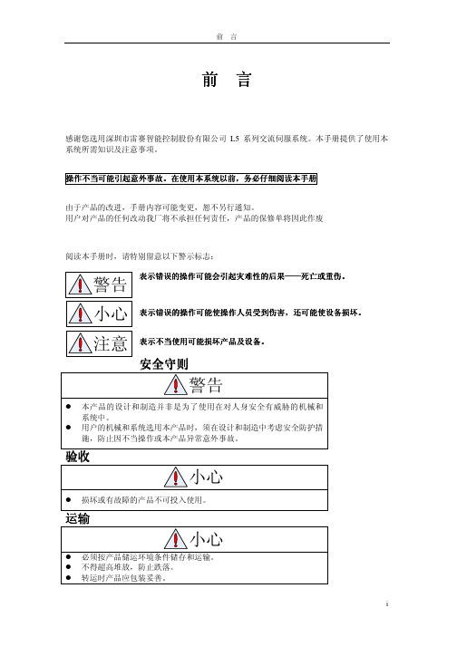
前 言感谢您选用深圳市雷赛智能控制股份有限公司L5系列交流伺服系统。
本手册提供了使用本系统所需知识及注意事项。
操作不当可能引起意外事故操作不当可能引起意外事故。
在使用本系统以前在使用本系统以前,,务必仔细阅读本手册由于产品的改进,手册内容可能变更,恕不另行通知。
用户对产品的任何改动我厂将不承担任何责任,产品的保修单将因此作废阅读本手册时,请特别留意以下警示标志:表示错误的操作可能会引起灾难性的后果表示错误的操作可能会引起灾难性的后果——————死亡或重伤死亡或重伤死亡或重伤。
表示错误的操作可能使操作人员受到伤害表示错误的操作可能使操作人员受到伤害,,还可能使设备损坏还可能使设备损坏。
表示不当使用可能损坏产品及设备表示不当使用可能损坏产品及设备。
不得拖曳电线、电机轴和编码器搬运伺服电机。
伺服驱动器及伺服电机不得承受外力及撞击。
接线必须正确而且牢固,否则可能会使伺服电机错误运转,也可能因接触不良损坏设备。
伺服电机U、V、W 端子不可反接,不可接交流电源。
伺服电机与伺服驱动器之间须直连,不能接入电容、电感或滤波器。
防止导电紧固件及电线头进入伺服驱动器。
电线及不耐温体不可贴近伺服驱动器散热器和伺服电机。
并接在输出信号直流继电器上的续流二极管不可接反。
出现报警后必须排除故障原因,在重新启动前,复位报警信号。
在瞬时停电后重新上电时,应运离机器,因为机器可能突然启动(机器的设计应保证重新启动时不会造成危险)。
前言 (i)第一章概述 (1)1.1 产品简介 (1)1.2 到货检查 (2)1.3 产品外观 (3)第二章安装 (4)2.1储存和安装环境 (4)2.2 伺服驱动器安装 (5)2.2.1安装方法 (5)2.2.2安装间隔 (5)2.3 伺服电机安装 (6)第三章接线 (8)3.1 标准接线 (8)3.1.1配线 (8)3.1.2位置控制方式 (9)3.1.3力矩、速度控制方式 (10)3.2 驱动器各端子功能 (10)3.2.1控制信号端口-CN1端子 (10)3.2.2编码器输入端口-CN2端子 (12)3.2.3通讯端口 (13)3.2.4 功率端口 (13)3.3 I/O接口原理 (14)3.3.1开关量输入接口 (14)3.3.2 开关量输出接口 (14)3.3.3脉冲量输入接口 (15)3.3.4模拟量输入接口(预留) (16)3.3.5伺服电机光电编码器输入接口 (17)第四章参数 (18)4.1 参数一览表 (18)4.2 参数功能 (21)4.2.1 【分类0】基本设定 (21)4.2.2 【分类1】增益调整 (24)4.2.3 【分类2】振动抑制 (28)4.2.4 【分类3】速度、转矩控制 (30)4.2.5 【分类4】I/F监视器设定...............................................................................- 35 -4.2.6 【分类5】扩展设定........................................................................................- 40 -4.2.7 【分类6】特殊设定........................................................................................- 42 - 第五章报警与处理...................................................................................................................- 44 -5.1 报警一览表..................................................................................................................- 44 -5.2 报警处理方法...............................................................................................................- 45 - 第六章显示与操作...................................................................................................................- 53 -6.1 概述..............................................................................................................................- 53 -6.2面板显示和面板操作....................................................................................................- 54 -6.2.1面板操作流程图.................................................................................................- 54 -6.2.2驱动器运行数据监视.........................................................................................- 55 -6.2.3系统参数设定界面.............................................................................................- 58 -6.2.4 辅助功能............................................................................................................- 60 -6.2.5 参数保存............................................................................................................- 62 -6.2.6异常报警.............................................................................................................- 62 - 第七章通电运行.......................................................................................................................- 63 -7.1运行前准备...................................................................................................................- 63 -7.1.1 接线检查............................................................................................................- 63 -7.1.2 上电时序图........................................................................................................- 64 -7.1.3 故障时序图........................................................................................................- 64 -7.2 试运行..........................................................................................................................- 64 -7.2.1 寸动控制............................................................................................................- 65 -7.2.2 位置控制............................................................................................................- 66 -7.2.3 速度控制............................................................................................................- 67 -7.2.4 转矩控制............................................................................................................- 69 -7.3 自动控制模式运行.......................................................................................................- 70 -7.3.1操作模式选择.....................................................................................................- 70 -7.3.2 位置模式............................................................................................................- 70 -7.3.3 速度模式............................................................................................................- 74 -7.3.4 转矩模式............................................................................................................- 77 - 第八章产品规格.......................................................................................................................- 80 -8.1驱动器技术规格............................................................................................................- 80 -8.2 伺服电机规格...............................................................................................................- 81 -8.2.1 60系列伺服电机安装尺寸.............................................................................- 82 -8.2.2 80系列伺服电机安装尺寸.............................................................................- 82 -8.2.3 90系列伺服电机安装尺寸.............................................................................- 83 -8.2.4 130系列伺服电机安装尺寸...........................................................................- 84 -8.3 配件选择......................................................................................................................- 84 - 第九章订货指导.......................................................................................................................- 85 -9.1 容量选择......................................................................................................................- 85 -9.2 电子齿轮比..................................................................................................................- 85 -9.3 停止特性......................................................................................................................- 85 -9.4 伺服系统与位置控制器选型计算方法.......................................................................- 86 -第一章概述1.1 产品简介交流伺服技术上世纪九十年代初发展至今,技术日臻成熟,性能不断提高,现已广泛应用于数控机床、印刷包装机械、纺织机械、自动化生产线等自动化领域。
FANUC Alpha系列伺服电机和伺服放大器结构和维修方法
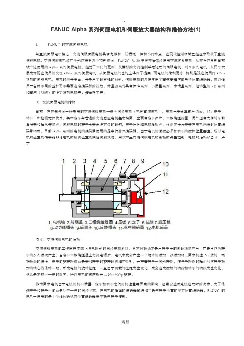
FANUC Alpha系列伺服电机和伺服放大器结构和维修方法(1)1. FANUC 的交流伺服电机与直流伺服电机相比,交流伺服伺服电机具有免维护,低损耗,体积小的特点,在现代控制领域已经逐步取代了直流伺服电机,交流伺服电机被广泛地应用到各个控制领域,FANUC 从80年代开始逐步使用交流伺服电机,从开发应用到目前被广泛使用的Alpha 系列伺服电机,经过了三代的更新,从模拟的交流控制单元驱动的伺服电机,到S系列电机,从而又发展成为现在使用的交流Alpha 系列伺服电机,从伺服电机的性能上得到了提高,而电机的体积更小,特别是现在使用的Alpha 系列的伺服电机,电机的型号更全,并采用了磁更强的材料,伺服电机的反馈使用了高速高精度的串行位置编码器,可以适用于各种不同的丝杠而不需要选定编码器的线数,并且该系列具有标准系列,小惯量系列,中惯量系列,经济型的AC系列和高压(380V)的HV系列电机等。
请参考下表:(1) 交流伺服电机的结构目前,在控制领域中所采用的交流伺服电机一般为同步电机(无刷直流电机),电机主要由三部分组成,即:定子,转子,和检测元件构成,其中定子与普通的交流感应电机基本相同,主要有定子冲片,三相绕组线圈,另外还有支撑转子前后端盖和轴承等组成,伺服电机的转子主要由多对极的磁钢,定子冲片和电机轴构成,检测元件由安装在电机尾端的位置编码器构成,目前Alpha系列的电机的编码器使用的是串行脉冲编码器,由于电机的激磁必须和转子的磁极位置垂直,所以电机的位置反馈要能够把电机的磁极位置反馈给伺服系统,用以产生交流伺服电机的激磁的矢量控制。
电机的结构如图4-1所示。
图4-1 交流伺服电机的结构交流伺服电机的工作原理实际上与电磁式的同步电机类似,只不过磁场不是由转子中的激磁绕组产生,而是由作为转子的永久磁铁产生,当定子三相绕组通上交流电源后,电机中就会产生一个旋转的磁场,该磁场将以同步转速Ns旋转。
根据磁场的特性,定子的旋转磁极总是要和转子的旋转磁极相互吸引,并带着转子一同地转动,使定子磁场的轴心线与转子磁场的轴心线保持一致,形成电机的旋转扭矩。