IVI配置文件的管理
配置管理程序

配置管理程序1.目的本程序的目的是规定并控制服务和基础设施组件,并保持正确的配置信息,为事件管理、问题管理、变更管理和发布管理的运作提供支持。
2.范围本程序适用于运维服务项FI的配置信息管理。
3.定义配置管理数据库(CMDB):包括所有与配置项及其状态和相互关系有关的信息的数据库。
配置管理数据库(CMDB)对所有IT组件、组件的不同版本和状态以及组件之间的相互关系进行跟踪。
在其最基本的形式下,一个CUDB可能是由一些纸质表格或一套清单组成。
基线:一个产品或系统在某一特定时刻的配置状况。
配置不仅体现了其产品或系统的结构,还反映了其具体内容,从而使得以后可以按照上述配置重建该产品或系统。
尽管被作为基准线的这个配置状态以后可能会发生改变,但这个基准线本身却保持不变。
这个基准线可以作为初始状态的一个参考或当前状态的一个对照。
4.职责软件产品研发部:■开发识别系统和确定配置项的命名规范;,规划和实施CMDB的组建及管理工作;' 组织配置审计并报告。
5.流程输入:组织中变更的信息、新IT组件的信息。
输出:其他流程、IT管理报告、新添加的和更新的配置记录。
流程活动:5. 1识别:定义和维护IT基础架构的物理组件和有关文档的命名规范和版本号,以及定义和维护这些组件之间的相互关系和相关属性。
记录在《配置记录说明书》中。
5. 1.2为识别IT组件,需要决定配置管理数据库(CUDB)的范围(宽度),分解的层数(深度) 以及详细的程度(细节)。
深度问题又可以进一步分为:层次的数目,需要跟踪的关系,命名规范以及属性。
识别包括:-定义范围:IT服务和它们对客户业务活动的贡献;特定的范围,如工作站、文档、打印和应用服务、中央处理器、数据库、IT系统和电话服务;硬件、软件和文件,如服务级别协议、规程、手册、技术规范说明书和项目计划等。
-定义属性:序列号、名称、制造商、版本号、位置、所有者。
-详细程度:为每一类配置项确定其属性的详细程度是建.配置管理的一个重要的方面;在确定属性的详细程度时,需要审慎地平衡变更需求、事件、问题、其它管理流程、以及用于支持配置管理所需的相关的负载量以及可利用的资源等方面的关系。
PIGOSS-IVI版-ESX 用户使用手册v1
PIGOSS爱维版运维监控系统ESXi监控操作手册摘要[本文档主要介绍了PIGOSS爱维版监控系统对于ESX虚拟化平台监控的操作手册]网利友联科技(北京)有限目录一、系统登录 (3)二、系统菜单 (3)2.1自动发现 (3)2.1.1自动发现 (3)2.1.2代理下载 (7)2.1.3指标定义 (8)2.2状态监控 (9)2.2.1资源监控 (9)2.2.2资源搜索 (17)2.3告警管理 (18)2.3.1未处理告警 (18)2.3.2已处理告警 (19)2.3.3告警分类 (19)2.3.4告警通知 (21)三、系统管理 (22)3.1系统配置 (22)3.1.1告警策略 (22)3.1.2展现配置 (28)3.1.3系统配置 (31)3.2系统维护 (36)3.2.1常用工具 (36)3.2.2数据维护 (39)3.2.3日志维护 (44)3.2.4自检管理 (49)3.3扩展功能 (51)3.3.1扩展指标 (51)3.3.2外部告警 (57)一、系统登录通过浏览器输入URL:http:// server IP,进入登陆界面,如图3-1所示:输入默认的用户名:admin 密码:admin 登入系统。
图3-1二、系统菜单2.1自动发现2.1.1自动发现1.进入方式点击左侧菜单栏的自动发现---自动发现,如图4-1所示。
图4-12.使用方法(1)自动发现设备1)探测agent设备选择探测方式为agent输入被探测资源的ip地址,如为单一主机,开始ip与结束ip相同;如为同一网段的多台主机,开始ip与结束ip应将该网段包含在其中。
点击开始按钮进行搜索。
如图4-2所示注:pigoss服务器会自动搜索安装了agent并将服务器ip地址设置为该pigoss服务器地址的设备。
图4-22)探测snmp设备选择探测方式为snmp输入被探测资源的ip地址,如为单一主机,开始ip与结束ip相同;如为同一地址段的多台主机,开始ip与结束ip应将该ip地址段包含在其中。
PIGOSS-IVI版Agent说明及安装配置
PIGOSS-IVI版Agent说明及安装配置PIGOSS爱维版运维监控系统Agent说明及安装配制摘要[ 本文档主要介绍了PIGOSS爱维版监控系统agent的安装]网利友联科技(北京)有限公司目录1、Agent说明 (3)2、JA V A 运行环境 (3)3、Agent的下载 (3)4、Agent的安装与配制文件解析 (3)5、Agent程序目录功能说明 (5)6、Agent的升级 (5)7、Agent的卸载 (5)1、A gent说明IVI支持多种采集方式,通过在被监控资源上安装agent代理进行采集,可以采集到很多通过SNMP 方式采集不到的指标。
由于agent 代理占用宿主机资源小,采集指标多样,大多数用户都将agent作为主要的采集方式。
2、J A V A 运行环境2.1、Java版本要求Agent的Java运行版本要求在1.5版本(包括)以上.2.2、Agent安装时对Java路径的添写要求Agent安装时Java的路径配制需要写全路径.例如: /usr/jre5/bin/java2.3、Java版本查看命令a. 系统默认的Java版本查看: 在任意路径下执行java –versionb. 指定路径的Java版本查看: 进入指定Java安装bin目录.执行./java -version2.4、Java所在路径查询命令a. 系统默认的Java路径查询: which javab. 系统中所有Java安装路径查询: find / -name java (查询出来结果的路径中一般都有版本的标识)3、Agent的下载3.1、启动IVI系统Web管理界面:在网络浏览器中直接访问运行中的IVI服务器IP 地址。
如:http://192.168.2.83.2、输入用户名和密码进行登录,点击左边栏的“系统工具---Agent管理----Agent下载”,IVI 提供Windows、LINUX、UNIX(AIX、SOLARIS、HP-UX等)的代理程序。
使用测量与自动化资源管理器 (MAX)与VXI说明书
IntroductionMeasurement&Automation Explorer(MAX)provides access to all yourNational Instruments DAQ,GPIB,IMAQ,IVI,Motion,VISA,and VXIdevices.With MAX,you can configure your National Instruments hardwareand software,add new channels,interfaces,and virtual instruments,executesystem diagnostics,and view the devices and instruments connected to yoursystem.MAX installs automatically with NI-VISA version2.5or higher or NI-VXIversion3.0or higher.MAX is available only for Win32-based operatingsystems.In this course manual addendum,you will examine MAX and use it toconfigure a VXI system.Measurement&Automation Explorer™,NI-VXI™,NI-VISA™,National Instruments™,and ™are trademarks of National Instruments Corporation.Product and company names mentioned herein are trademarks or trade names of their respective companies.370341A-01©Copyright2000National Instruments Corp.All rights reserved.December2000Using Measurement &Automation Explorer ™(MAX)with VXIVXI Course Manual Addendum Exercise 1Objective:To examine MAX.unch MAX by double-clicking on the desktop icon or selecting Start»Programs»National Instruments»Measurement &Automation .2.After launching,MAX displays the dialog box shown below.You canuse this dialog to configure MAX to search for new devices each timeyou launch it or only when you refresh (<F5>or View»Refresh ).Also,you can configure the dialog box to appear the next time youlaunch MAX.Do not change the settings and click on OK .Figure 1.MAX User PreferencesNote Y ou selected not to search for new devices when MAX launches,so MAX will not show the updated system view if there are any changes to it.Remember to refresh after making any changes.To change these preferences,you can access this dialog box by selecting Tools»User Preferences....MAXiconUsing Measurement&Automation Explorer™(MAX)with VXI3.Expand the Devices and Interfaces folder by clicking on the plus(+)sign next to it.Select VXI System0and expand it also.ExpandFrame0.The MAX interface should appear as shown below.1231Configuration Tree2Configuration View3Task ListFigure2.The MAX InterfaceConfiguration TreeThe configuration tree shows a hierarchical view of the instruments in yoursystem.In the setup shown in Figure2,MAX shows a VXI system with oneVXI chassis(Frame0),a National Instruments VXIpc-870embeddedcontroller,a Wavetek1375arbitrary waveform generator,and a NationalInstruments MIO-64E-1multifunction data acquisition board.©National Instruments Corporation3VXI Course Manual AddendumUsing Measurement &Automation Explorer ™(MAX)with VXIVXI Course Manual Addendum The following MAX toolbar appears when you select the VXI system in theConfiguration Tree:Properties —Displays properties of the selected VXI system.Run VXI Resource Manager —Runs VXI Resource Manager (Resman)for the selected VXI system.NoteBecause NI-VXI 3.0or higher supports multiple VXI systems,properties apply to the currently selected VXI system.Resman also runs for only the selected VXI system.To run Resman for all VXI systems,select Tools »NI-VXI »VXI Resource Manager .System PropertiesY ou can examine the properties for the selected VXI system by clicking onthe Properties button from the toolbar or right-clicking on the particularVXI system and selecting Properties ,as shown below.Figure 3.System Properties for VXI System 0In addition to viewing the properties,you can also launch Resman forthis VXI system,access the hardware configuration for the systemcontroller,and create a new VMEdevice.Using Measurement &Automation Explorer ™(MAX)with VXI©National Instruments Corporation 5VXI Course Manual Addendum4.Examine the VXI System 0properties.Right-click on VXI System 0and select Properties .The properties dialog box appears as shown below.Figure 4.Properties Dialog for VXI System 0This dialog box reports the device status.If there is a problem with this system,you can access online help by clicking on the Troubleshoot …button.The properties dialog box also shows you the device type and whether the device isenabled.Using Measurement&Automation Explorer™(MAX)with VXI5.Select the Settings tab,shown below.Figure5.VXI System0SettingsYou can use this tab to change the VXI system number and Resmandelay for this specific VXI system.(In this exercise,do not change thesettings.)VXI Course Manual Using Measurement &Automation Explorer ™(MAX)with VXI©National Instruments Corporation 7VXI Course Manual Addendum6.Select the Interrupt Levels tab,shown below.Figure 6.VXI System 0Interrupt Levels You can use this tab to assign interrupts to specific controllers and set the mapping for each interrupt level.(In this exercise,do not change the settings.)In the Assignment field,you can select four options from the pull-down menu:•Auto —Automatically assign to a programmable handler,usually the local controller.•Local —Assign the interrupt level to the local controller.•Choose LA —Choose the Logical Address of the controller that will handle this interrupt.•None —Do not assign the interrupt level to any controller.In the Mapping field,you can select three options for mapping the interrupts:•Auto —Auto mapping (maps toward root if root is the handler;otherwise,does not map).•Source —Map away from the root (source the interrupt).•None —Do notmap.Using Measurement &Automation Explorer ™(MAX)with VXIVXICourse Manual Addendum 7.Click on the Assist Me …button.The Interrupt Levels dialog box appears,as shown below.Figure 7.VXI System 0Interrupt Assistant If you are not sure how to set the interrupt assignments and mapping,you can use this dialog box for detailed descriptions of all the settings and to set the options separately for each interrupt.(In this exercise,do not change the settings.)8.Close the Interrupt Levels and VXI System 0Properties dialogboxes.Using Measurement &Automation Explorer ™(MAX)with VXI©National Instruments Corporation 9VXI Course Manual AddendumConfiguration ViewFigure 8.VXI Address Map View —System Resources WindowThe configuration view (the center window)shows the registers/address space requested by various devices in A16,A24,and A32space.In this particular setup,the two devices have registers in A16and A24address space,and the system controller (VXIpc-870)has registers in A16and A32address space.9.Look carefully at the ranges being used in A16address space by eachinstrument.Recall the formula for the base of these 64byte (0x40)windows:base address =0xC000+(logical address *0x40)Task ListThe task list (the right window)includes an interactive task list to guide you through VXI system configuration and other basic tasks.10.Select various items in the configuration tree and review the informationin the task list.Notice that the task list contents change according to the interface and device youselect.Using Measurement &Automation Explorer ™(MAX)with VXIVXI Course Manual Addendum Device Properties in MAX11.Select the Wavetek 1375in the configuration tree.Notice that MAXdisplays the information about the device in the Attributes tab of the configuration view.Here you can see that the Wavetek 1375is at Logical Address 1,the manufacturer ID is 4094,and the device resides in slot 2in your VXI chassis.Also,this window shows the resources used by the Wavetek 1375.The A16space for this device contains the Configuration Registers.The A24space is scratch pad RAM for storing waveforms.Figure 9.Right-Clicking on a Device to Examine Its Properties12.You can examine properties of devices in the system by right-clickingon a device and selecting Properties or highlighting the device and clicking on the Properties button on the toolbar.Right-click on the Wavetek 1375,as shown above.Review the properties information and close the dialogbox.Configuring Devices in MAXY ou can configure some VXI devices(for example,all National InstrumentsMITE-based controllers)through software.Y ou can use MAX to configurethese devices.13.Right-click on the VXIpc-870controller in the Configuration Tree andselect Hardware Configuration.The dialog box shown below appears.Figure10.VXIpc-870Hardware Configuration through MAXGeneral—Use this tab to load and save configurations from file.This isuseful when backing up your system.Device—Use this tab to configure the MITE-based device logicaladdress and interrupt configuration.Shared Memory—Use this tab to set up the shared memory.For moredetails on shared memory,see the online help or visit the NationalInstruments Web site to download the shared memory application note.VXI Bus—Use this tab to configure how MITE-based controllersinterface to the VXI bus(timeout,etc.).PCI—Use this tab to configure the MITE chip(which resides on thePCI bus,hence the tab name).Watchdog—Use this tab to enable the watchdog timer.SMB—Use this tab to configure the front panel SMB connectors toprovide or source clocks and triggers.14.Close the hardware configuration dialog box.Configuring MAX15.Y ou can customize MAX to meet your system needs.SelectTools»NI-VXI»VXI Options to get the VXI options dialog boxshown below.Review the options and close the dialog box.Figure11.VXI Options16.To set the NI-VISA options,select Tools»NI-VISA»VISA Options.Use this dialog box to tell the driver to run Resman on startup.Y ou canalso set the VISA options shown below.Review the options and close the dialog box.Figure12.VISA OptionsHelp in MAXMAX brings online support to a new level.The MAX help files featurecommon questions gathered from several years of technical support calls,as well as helpful hints,references to application notes,and procedures forsetting up a large variety of systems.If MAX resides on a networkedcomputer,you have a Web link from MAX to the National InstrumentsTechnical Support home page and the NI-VISA and NI-VXI home pages.Y ou can access the following help resources through links in MAX.Online Problem Solving and Diagnostic Resources•KnowledgeBase—A searchable database containing thousands offrequently asked questions(FAQs)and their corresponding answers orsolutions,including special sections devoted to our newest products.The database is updated daily in response to new customer experiencesand feedback.•Troubleshooting Wizards—Step-by-step guides lead you throughcommon problems and answer questions about our entire product line.Wizards include screen shots that illustrate the steps being described andprovide detailed information ranging from simple getting startedinstructions to advanced topics.•Product Manuals—A comprehensive,searchable library of the latest editions of National Instruments hardware and software productmanuals.•Hardware Reference Database—A searchable database containing brief hardware descriptions,mechanical drawings,and helpful images of jumper settings and connector pinouts.•Application Notes—A library of more than100short papers addressing specific topics such as creating and calling DLLs,developing your own instrument driver software,and porting applications between platforms and operating systems.Software-Related Resources•Instrument Driver Network—A library of hundreds of instrument drivers for control of standalone instruments via GPIB,VXI,or serialinterfaces.Y ou also can submit a request for a particular instrument driver if it is not in the library.•Example Programs Database—A database with numerous example programs for National Instruments programming environments.Y ou can use them to complement the example programs already included with National Instruments products.•Software Library—A library with updates and patches to application software,links to the latest versions of driver software for NationalInstruments hardware products,and utility routines.17.Examine some of the help resources available in MAX.OpenHelp»HelpTopics»NI-VXI.Suppose you want to configure amultimainframe VXI system.From the Contents tab,select HowDo I…?»Configuration»Configure a multiple-mainframe system.Y ou can resize this window and read about the issues involved with this type of configuration.Notice the reference to an application noteavailable from the National Instruments Web site.Y ou can easilydownload this application note by returning to the MAX interface and selecting Help»National Instruments on the Web»VXI Home Page to launch your browser.On this page is a link to the Support Resources page,where you can download application notes.18.Close the MAX help.Software Information19.Another helpful MAX feature is its ability to gather and displayinformation about your system for your reference.Expand the Software folder in the configuration tree.Expand the NI-VISA icon and select visa32.dll.The window should appear as shown below.Figure13.The MAX Software InformationIn this window,you can view the versions of all pertinent NationalInstruments drivers in your system.This information is very important when troubleshooting a system.End of Exercise1Exercise2Objective:To add a fictitious VME device to your system.It is often necessary to use a VME device in a VXI system.Because theVME specification does not implement configuration registers,if you wantto use VME devices in your VXI system,you must tell the NI-VXI driverwhat resources a particular VME device uses.In a VXI system,Resman uses the VXI configuration registers to identifyeach VXI device,its device class,model and manufacturer,and addressspace requirements.Because VME devices do not have the standardizedVXI register set,you must manually enter the information(normallyencoded in this VXI-defined register set)for your VME device beforeResman can properly configure it.Y ou can use MAX to add a VME deviceto your system manually.unch MAX if it is not already running.Expand the Devices andInterfaces folder in the configuration tree and right-click on VXISystem0.From the pop-up menu,select Create new VME device….The Create New…window appears as shown below.Figure14.Create New VME Device WindowBecause you can have multiple VXI systems in the same configuration, there is a System Number pull-down menu.Because there is currently only one VXI system,keep the VXI System0selection.Next,assign this device a pseudo logical address between255and512.(Select any number in this range.)Finally,specify the frame and the slot within the frame where this device resides.The only frame in your system is Frame 0,so keep this selection.Because this VME device does not really exist, you may select any slot you want.2.Click on the Next>button to continue.In the next window(shownbelow),you can create a new VME profile.Figure15.Create a New Profile Window3.You can use the pull-down menu in this window to select previouslycreated VME profiles or create a new one.A profile describes themanufacturer ID,model code,and resources that this VME devicerequires.No VME profiles are created yet,so click on Next>to create one.Name your VME device My VME Device,as shown below.Figure16.Profile Name,Manufacturer ID,and Model Code4.In the Manufacturer pull-down menu,select Act Tech as themanufacturer for this fictitious device.5.Select the Model Name pull-down menu for a list of known VMEdevices manufactured by Act Tech.This list is empty,so you need to add this new device yourself.Click on the...button next to the Model Name pull-down menu.The dialog box shown below appears.Figure17.Adding a New Act Tech VME Device6.Click on New…and fill in the parameters shown below.Click on OK.Figure18.The New VME Model From Act Tech7.The new VME device appears in the Model Name Editor window.Clickon OK again to confirm the change and return to the Device Wizard.8.Select the device you just added in the Model Name menu.Y our screenshould appear as shown below.Figure19.Device Wizard Showing New VME Model and Manufacturer9.Click on the Next>button to add resources used by this device.Using Measurement &Automation Explorer ™(MAX)with VXI©National Instruments Corporation 21VXI Course Manual Addendum 10.Click on the Add …button and select Address Range »A24.In theSetting column,you can enter the range of registers this device uses.Type in the value 0x0 - 0x100000and press <Enter>.Figure 20.Requested Address Space for the New VME Device11.Click on Next >and Finish to complete the process of adding a VMEdevice.Notice that in the MAX configuration tree,your VME devicehas an exclamation point.This means you need to run Resman again toreconfigure thesystem.Using Measurement &Automation Explorer ™(MAX)with VXIVXI Course Manual Addendum 12.Run Resman and notice that the VME device remains in the system andthe exclamation point disappears,as shown below.You can edit theconfiguration parameters of this fictitious VME device through itsproperties.You can access the Properties menu by right-clicking on theVME device or selecting Tools »NI-VXI »VME Profiles .In the VMEProfiles window,you can manipulate the profiles you created.You canremove them,add a new one,or change their properties.Figure 21.MAX Showing VME Device in Configuration Tree13.To remove the VME device,right-click on it and select Delete .Thedevice disappears,but its profile is still available for future use.End of Exercise2Worldwide Technical Support and Product InformationNational Instruments Corporate Headquarters11500North Mopac Expressway Austin,Texas78759-3504USA Tel:5127940100Worldwide OfficesAustralia0398795166,Austria0662*******,Belgium027570020,Brazil0112845011,Canada(Calgary)4032749391, Canada(Ottawa)6132335949,Canada(Québec)5146948521,China(Shanghai)021********,China(ShenZhen)0755*******,Denmark45762600,Finland0972572511,France0148142424,Germany0897413130, Greece3014296427,Hong Kong26453186,India91805275406,Israel036120092,Italy02413091,Japan0354722970, Korea025967456,Mexico52807625,Netherlands0348433466,New Zealand099140488,Norway32277300,Poland022*******,Portugal35117269011,Singapore2265886,Spain916400085,Sweden0858789500, Switzerland0562005151,Taiwan022*******,United Kingdom01635523545。
3-H3C+iVS系统管理及配置
9
H3C网站输入授权码和host.id
上传host.id文件(服务器主机信息文件), 填写用户信息,获取激活码(license文件)
10
License操作流程
最后在License申请界面导入license文件并查看规 格
11
模板配置
8
H3C网站输入授权码和host.id
登录->服务支持->license首次激 活申请,选择监控产品,输入授权码
授权码(用于申请激活文件) 6DU68UXMXNULNEWCQN6N27EAR2 54CV44WAYXX8UNU6JUSQKESL82 76FV7US5LGDTCYFYTMGLS63L2S WP7LQ6XA9AVSGU5HWVPZ8XMHPR
H3C iVS系统管理及配置
ISSUE 1.0
日期:
杭州华三通信技术有限公司 版权所有,未经授权不得使用与传播
课程目标
学习完本课程,您应该能够:
熟悉IP监控系统的管理机制 掌握IP监控系统的管理配置
目录
平台管理 组织管理 设备管理 业务和计划管理 告警和日志管理
Web客户端登录
某资源是否可以进行解除划归操作,可以根据资
25
目录
平台管理 组织管理 设备管理 业务和计划管理 告警和日志管理
设备管理
管理分为本域和外域管理
业务分为设备添加、注册上线、参数配置
27
中心服务器基本配置
包含服务器参数、服务器时间配置、本域配置、跨域编 码配置和云台释放配置
计划备份
34
摄像机组管理
国家仪器 IVI合规性软件包4.2说明书
RELEASE NOTESIVI Compliance Package Version 4.2These release notes contain installation and uninstallation instructions anda list of installed components for the IVI Compliance Package 4.2.Note If you are upgrading from IVI software versions earlier than IVI Compliance Package 3.0, refer to the IVI Compliance Package 3.0 Release Notes for upgradeinformation. You can download a copy of the release notes from the National Instruments Web site at /info . Enter the Info Code icp3rn .IntroductionThe IVI Compliance Package is a software package that contains IVIclass drivers and support libraries necessary to develop and useapplications that leverage IVI instrument interchangeability. TheIVI Compliance Package also is based on and is compliant with thelatest version of the instrument programming specifications definedby the IVI Foundation. You can use the IVI class drivers in theIVI Compliance Package with IVI specific drivers.IVI class drivers implement functions and attributes for controlling aninstrument within a specified class, as defined by the IVI Foundation.The IVI Compliance Package provides IVI class drivers for the followingspecifications:•IviDCPwr •IviDmm •IviFgen •IviPwrMeter •IviRFSigGen •IviScope •IviSpecAn •IviSwtch™•IviCounter•IviUpconverter•IviDownconverter•IviDigitizerIVI specific drivers are drivers for the most popular instruments from allof the currently defined IVI Foundation classes and from the largestinstrument manufacturers including National Instruments, AgilentTechnologies, and Tektronix. You can create IVI specific driversyourself,or download them from /idnet. InstallationNational Instruments recommends that you close all other applicationsbefore you install the IVI Compliance Package.For system requirements, refer to the NI IVI Compliance Package Readme,which you can access by selecting Start»All Programs»NationalInstruments»IVI»IVI Compliance Package Readme.The IVI Compliance Package is included with various NationalInstruments distributions, such as National Instruments Device Drivers,Switch Executive, and Calibration Executive. You also can obtain theIVI Compliance Package as a stand-alone Web-only distribution.If you install a product that is dependent on the IVI Compliance Package,such as Switch Executive, you do not need to install this separateIVI Compliance Package because it is already included in the productinstallation.To install the IVI Compliance Package from the National InstrumentsDevice Drivers media, insert the media and follow the installationsteps.When prompted with feature selections, enable theIVI Compliance Package.To install the stand-alone, Web-only IVI Compliance Package 4.2,complete the following steps:1.Download the IVI Compliance Package 4.2 self-extracting archivefrom /downloads by navigating through the Drivers andUpdates link.2.Double-click the self-extracting archive to launch the installer.3.Click OK to begin installation.4.Follow the directions that appear on the screen.IVI Compliance Package Release © National Instruments Corporation 3IVI Compliance Package Release NotesNoteThe IVI Compliance Package Web distribution does not install NI-Spyor Measurement & Automation Explorer (MAX). NI-Spy tracks the calls your application makes to National Instruments test and measurement drivers, such as NI-VXI and NI-VISA. You can use MAX for IVI configuration support. You can use IVI software without these components, but you will not have the features these products supply unless you install them. If you have installed other National Instruments products, such as the National Instruments Device Drivers media, you might already have NI-Spy and MAX installed.If you install a National Instruments product that installs MAX after installing the Web distribution of the IVI Compliance Package, you must reinstall theIVI Compliance Package to be able to use the updated IVI configuration userinterface in MAX. You must have MAX 4.2.1 or later installed to use the IVI configuration utility in MAX.Installed ComponentsDepending on the software support you select when you install theIVI Compliance Package, the installation includes one or more of thefollowing components:•IVI class drivers •IVI class driver LabWindows ™/CVI ™ support •C++ wrappers for IviDmm , IviScope , IviDCPower , IviSwtch , and IviFGen class drivers for Measurement Studio (Windows XP only)•IVI class driver wrappers for supported versions of LabVIEW •IVI class simulation drivers •IVI-COM adapters (32-bit only)•IVI class driver examples for LabWindows/CVI, LabVIEW, and Measurement Studio •IVI Shared Components 2.1.0•IVI configuration plug-in for MAX 4.2.1 and later •Online helpUninstallationIf you no longer want to use IVI software components, complete thefollowing steps to uninstall them.Note If you installed the IVI Compliance Package as part of another distribution that depends on the IVI Compliance Package, you cannot uninstall theIVI CompliancePackage without uninstalling the dependent product.CVI, LabVIEW, National Instruments, NI, , the National Instruments corporate logo, and theEagle logo are trademarks of National Instruments Corporation. Refer to the Trademark Information at/trademarks for other National Instruments trademarks. The mark LabWindows is usedunder a license from Microsoft Corporation. Windows is a registered trademark of MicrosoftCorporation in the United States and other countries. Other product and company names mentionedherein are trademarks or trade names of their respective companies. For patents coveringNational Instruments products/technology, refer to the appropriate location: Help»Patents in yoursoftware, the patents.txt file on your media, or the National Instruments Patent Noticeat /patents .© 2003–2010 National Instruments Corporation. All rights reserved.370733E-01Aug101.Select Start»Control Panel»Add or Remove Programs .2.Select National Instruments Software and click Change/Remove .3.Select NI IVI Compliance Package 4.2 and click Remove .Note After you uninstall the IVI Compliance Package, IVI Shared Components remain on your computer. To remove the remaining components, select Start»Control Panel»Add or Remove Programs , select IVI Shared Components , and click Change/Remove .LabWindows/CVI Version SupportThe IVI Compliance Package provides support only for the latest versionof LabWindows/CVI installed on your computer. If you install the IVICompliance Package with LabWindows/CVI installed and then upgrade toa later version of LabWindows/CVI, complete the following steps tomodify the IVI Compliance Package installation to get IVI support for thelater version of LabWindows/CVI:1.Select Start»Control Panel»Add or Remove Programs .2.Select National Instruments Software and click Change/Remove .3.Select NI IVI Compliance Package 4.2 and click Modify .4.For the LabWindows/CVI Support feature under IVI Class Drivers , select Remove this feature and complete the installation.5.Repeat steps 1–3.6.For the LabWindows/CVI Support feature under IVI Class Drivers ,selectInstall this feature to a local drive and complete theinstallation.This process removes IVI class driver support for the previous version ofLabWindows/CVI and adds this support for the later version ofLabWindows/CVI.。
配置管理程序
配置管理程序1、目的通过设计配置管理过程,定义并核实相关的IT基础架构的配置项记录的准确性并维护准确的信息,使其能够为其他的服务管理过程提供支持(如事件管理、问题管理、变更管理和发布管理)。
2、范围配置管理程序所管理的范围包括(根据与客户合同要求)需要承担系统管理和维护职责的IT运行环境。
其中,配置基线的保存和维护,以及配置项的建立、修改、审计工作都是由配置管理流程来完成的。
但需要说明的是,配置项的变动是由发布管理和变更管理来控制的,变动后的操作则是由配置管理来执行的。
配置项(CI)包括系统运行环境的部署环境设备、系统软件、服务文档等,及服务环境中涉及的客户信息配置。
具体活动包括识别、控制、汇报和审核等行为。
3、角色和职责配置管理流程主要有3个角色:配置经理、配置管理员、配置审核员。
3.1配置经理配置经理是配置管理具体活动的负责人,包括带领执行配置项的鉴别、监控、控制、维护、审计等工作。
配置经理的主要职责:1)确定配置管理过程的计划;2)对配置项进行识别和控制;3)判断配置项的修改与更换,并与变更经理保持紧密沟通;4)确保配置管理过程在整个组织内得到良好的传达和沟通;5)规划和制定配置管理的范围;6)审批配置管理数据库库结构的变更;7)建立配置管理数据库的安全控制手段,确保惟有授权的配置项才被使用;8)确定配置项命名和编号的规范,并确保所有配置项具有单一名字;9)确定配置项的分类、配置项属性、配置项的关系类型和配置项之间的关系;10)制定配置项(CI)的收集和CMDB建设的步骤;11)确定配置管理报表的格式和内容;12)定期对配置管理数据的内容进行审计和验证;13)定期主持配置管理回顾会议;14)负责配置管理相关报告的编写,包括配置管理报告、配置审核报告以及配置状态报告。
配置经理主要技能要求:1)熟悉变更发布管理、配置管理、事件管理和问题管理流程及其他们之间的关系;2)了解客户的IT基础架构、系统应用和业务环境;3)了解配置项之间的关系;4)较强的沟通技巧;5)很强的团队领导能力。
基于ivi—td的测试资源管理设计与实现
青岛
26 5 ) 6 5 5
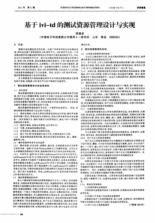
随 着 自动 化 测 试 技 术 的发 展 .出现 了 各 种 各 样 的 自动 化 测 试 设 2 测 试 资 源管 理 的 实现 ’ 备 , 时也 出现 了多 种多 样 的 A E软 件 平 台 。 E软 件 平 台是 一 个 开 同 T AT 21 实 现 测试 资 源 管 理 的 流程 . 发 测试 程 序 和 为 测 试 程 序提 供 运 行 环 境 的 可视 化 测 试 软 件 平 台 。 以 在 在运 行 主测 试 程 序之 前 . 先 对 测 试资 源 进 行 扫 描 、 始 化 , 看 首 初 查 往 自行 开 发 的 软 件 平 台 中 ,很 少 有 对 测 试 资源 采 取标 准 化 的 管 理 方 测 试 资 源及 其 连 接 情 况是 否 正 常 。 式 , 得 A E在 更 换 、 加 或 删 除 其 测 试 资源 时 , 得 不 修 改 原 有 的 使 T 添 不 211 若 不 正 常 . .. 工作 人 员 将 对 测试 资源 或 测 试 资 源 与 接 口问 的 连 接 测试 代 码 来 完 成 测 试 任 务 , 而 降 低 了 A E软 件 平 台 的可 移 植 性 . 从 T 使 情 况 进行 检 查 、 误 、 排 检查 、 误 后 , 排 重新 进 行 资 源 初 始 化 , 是 否 正 常 看 得开 发 人 员 做无 谓 的重 复 工 作 ,也给 测 试 的 操 作 人 员 带 来 了不 便 . 并 工 作 . 不 正 常 继 续检 查 、 误 直 到 显示 “ 切 正 常 ” 若 排 一 为止 。 且 增 加 A E 的开 发 成 本 , 长 A E 的研 制 周 期 , 论是 从 人 力 还 是 财 T 延 T 无 21 如 果 正 常 . 按 测 试 需 求 分 别 对 仪 器 资 源 及 其 设 备 驱动 , 源 .. 2 则 资 力 的角 度 来讲 都 造 成 了 巨大 的浪 费 。因 此 , 设 计 A E 软 件 平 台 时 。 在 T: 地址 . 户 自定 义 资源 。 器 与 开关 接 口的 连 接 进 行 配 置 。 然后 , 其 用 仪 将 测 试 资 源 管理 的设 计 是 非 常 重 要 的 。 配置 保 存 于 相 应 的数 据 库 中 。在 运 行 主 测 试 程 序 时 , 试程 序 将 调用 测 本 文 便 借 鉴 当今 典 型 的测 试 软 件 平 台 对 测 试 资 源 的模 块 化 管理 各 项 配 置 及 用 户 自定 义 资 源 。 的设 计 思 想 , 提 高 A E软 件 平 台 的 可移 植 性 和 通 用 性 。 来 T 22 模 块 化 的设 计 与 实 现 . 模 块 化 就 是按 仪 器 操 作 功能 划 分 成 若 干 个模 块 , 每个 模 块 完 成 一 1 测试 资源 管 理 设计 的 总体 规 划
写出配置管理的基本过程

配置管理的基本过程介绍配置管理是软件开发和IT运维过程中不可或缺的一部分,它涉及到对软件、硬件和相关文档的版本控制、变更管理和发布管理等。
本文将探讨配置管理的基本过程,包括配置识别、配置控制、配置审查和配置状态管理等方面。
配置识别配置识别是配置管理的第一步,它的目标是确定系统中需要纳入配置管理的实体,例如软件、硬件、文档和配置项等。
配置识别过程包括以下几个步骤:1.确定配置项:根据系统的需求和范围,确定需要进行配置管理的实体。
配置项可以是软件代码、文档、服务器硬件等。
2.标识配置项:为每个配置项分配一个唯一的标识符,以便将来能够对其进行跟踪和管理。
标识符可以采用系统内部的编号或者统一的命名规则。
3.建立配置管理库:配置管理库是存储和管理配置项的地方,可以使用版本控制系统或者配置管理工具来实现。
在建立配置管理库之前,需要确定适合系统的架构和技术选型。
配置控制配置控制是确保配置项在其整个生命周期内保持一致性和可追溯性的过程。
它的目标是管理配置项的变更,确保所有变更都经过审查和授权,并正确地应用到相应的环境中。
配置控制包括以下几个步骤:1.变更请求管理:在有变更请求时,需要建立一个变更请求管理系统来跟踪和管理变更。
变更请求应包含变更的描述、原因和影响分析等信息。
2.变更评估和授权:对于每个变更请求,需要评估其对系统的影响,并由相应的审批人员进行授权。
评估和授权可以基于变更请求的优先级、风险评估和资源可行性等因素进行。
3.变更实施:经过授权的变更请求将被实施到系统中。
在实施变更之前,需要进行必要的测试和验证,确保变更不会引入新的问题。
4.变更回退:如果实施中出现问题或者变更后引入了新的错误,需要有回退的计划。
回退计划应事先制定,并在需要时能够快速、安全地回退到变更之前的状态。
配置审查配置审查是确保配置项满足质量标准和要求的过程。
它的目标是评估和审查配置项的设计、实现和性能,并确保其符合预期的功能和性能要求。
基于LabVIEW的文件管理要点

•
为之后要编写的所有代码段创建占位符,避免改变项目文件
•
使用.lvlib文件来避免修改项目文件
如果需要进行更改,可让某个开发员签出项目文件并进行编 辑
•
确保所有其他开发人员立即获得最新版本的项目文件
使用LabVIEW配置SVN源代码控制
演示
将VI保存于SCC时的考量因素
哪些文件应该放置在源代码控制之下?
VI 文档
o
使用源代码控制跟踪修订并记录到需求文档中
配置文件 类型定义
如果是*.lvproj文件,会怎么样?
是否也需要将*.lvproj文件放置在SCC下?
LabVIEW *.lvproj文件是一个XML文件,包含:
• • •
项目包含的文件的链接 项目设置 “虚拟项”,比如程序生成规范
所有开发人员必须采用*.lvproj文件的最新版本,以确保获 得所有最新的依赖关系和资源
是否需要将*.lvproj文件放置到SCC下?
重命名或添加项目中的文件时,*.lvproj文件会随之变化并需要从源代码控制中 签出,这样会影响使用该项目的所有开发人员。
避免交叉链接
将所有文件添加至LabVIEW项目 考虑依赖关系 避免因创建多个备份导致代码重复 通过复用库在项目之间共享代码 确保VI名称的唯一性
总结
项目浏览器可用于组织应用程序和预防开发陷阱。
• • • •
使用自动填充和虚拟文件夹来自定义文件的组织方式 通过文件视图可在移动文件时保留链接 动态分组已链接的资源 考虑依赖关系
更多选择
Microsoft Visual Source Safe Microsoft Team Foundation Server Rational ClearCase PCVS (Serena) Version Manager MKS Source Integrity Seapine Surround SCM Borland StarTeam Telelogic Synergy
网络锁使用说明_服务器端找不到锁_100128

精锐IV网络锁说明目录精锐IV网络锁说明 (1)1、安装加密锁驱动程序 (2)2、安装网络锁服务程序 (3)3、工具及配置文件说明 (5)3.1网络锁服务管理工具 (5)3.1.1添加主机 (5)3.1.2网络锁参数配置 (6)3.1.3使用服务管理程序 (8)3.2配置文件 (9)3.2.1管理配置文件 (9)3.2.2服务配置文件 (9)3.2.3客户端配置文件 (11)4、网络锁访问测试 (11)5、常见问题处理(FAQ) (13)附录 (16)1、检查服务器端的TCP、UDP端口是否被占用 (16)网络版可以允许多个软件的实例同时访问连接在服务器上的同一个加密锁,即对加密锁进行共享。
通过限制同时运行的客户端软件数目,可以达到对软件的使用进行控制的目的。
相对于单机版来说,网络版不仅需要保护软件不被非法复制,同时必须严格限制同时运行的软件数目。
1、安装加密锁驱动程序加密锁默认为有驱模式,需要安装驱动程序。
安装SDK 的过程会自动安装精锐IV 的设备驱动程序,在一些情况下您可能需要单独安装驱动程序(例如将整个SDK 复制到其它计算机中直接使用、发布您的软件),这时候您需要使用SDK中提供的驱动程序安装工具。
该工具位于%SDK%\Drivers 目录下,名称为“InstWiz3.exe”。
这是一个WIN32 可执行程序,可以接受以下命令行参数:♦/INSTALL 安装驱动程序(该选项为默认选项)♦/UNINSTALL 卸载驱动程序♦/NOGUI 不显示安装界面这些命令行参数可以组合使用,例如,您可以运行“InstWiz3.exe /uninstall /nogui”来隐式卸载设备驱动。
该工具也可以用来检测当前系统中精锐IV 设备驱动程序的安装情况:运行InstWiz3.exe,工具将自动检测并汇报驱动程序的安装情况。
有几种办法可以测试驱动程序是否安装成功:1. 插入精锐IV设备,检查硬件设备列表中是否出现正常的Senselock SenseIV v2.x设备(“设备管理器”Æ“智能卡阅读器”下);对于Windows98、Window2000 或更高版本,如果设备是第一次插入,系统会自动提示“找到新设备”并完成安装;2. 插入精锐IV设备,运行开发测试工具或者用户工具,看是否能成功访问设备;如果您对设备驱动程序的安装过程非常熟悉,您也可以选择手工的方式安装精锐IV 设备驱动。
PIGOSS-IVI版系统安装文档v1
PIGOSS-IVI版系统安装说明摘要[本文档主要介绍了安装centos及pigoss爱维版系统]网利友联科技(北京)有限公司一、虚拟机上安装CentOS 5.5Pigoss IVI监控系统要在centos 5.5 上运行,所以我们首先要在虚拟机上安装一个centos5.5 下面是安装centos 5.5 时需要注意的几个步骤:1、在分区时,总共分为三个区。
首先点击“新建”,弹出分区窗口,在挂载点里展开菜单中选择“/boot”,大小为“5000(5G)”;再点击“新建”,在类型的展开菜单中选择“swap”,大小为“5000(5G)”;再点击“新建”,在挂载点展开菜单里选择“/”,在大小下面选择“使用剩余的空间”。
2、安装Centos 5.5:选择“开发”,将右侧项目全选,然后“next”3、勾选“SSH”,防火墙选择“禁用”,selinux设置“强制”然后“next”4、登入界面:二、安装PIGOSS-IVI版安装了操作系统后,运行SSH Secure Shell Client,点击Quick Connect。
弹出窗口,Host Name输入:192.168.1.xxx(与CentOS中配置的IP地址相同),User Name 输入:root,点击“Connect”(此处Port:22为默认值)1、返回命令窗口,系统默认字符更改,输入下列命令:echo LANG=\"zh_CN.gb2312\" > /etc/sysconfig/i18nechoLANG=\"zh_CN.gb2312\">> /etc/profileechoLANGUAGE=\"zh_CN.gb2312\">> /etc/profileechoLC_CTYPE=\"zh_CN.gb2312\">> /etc/profileechoGST_ID3_TAG_ENCODING=GBK>> /etc/profile2、登陆后,窗口左侧框内为本机文件,右侧框内为围虚机文件,在左侧找到下列四个文件,拖入右侧(文件复制到右侧完成后,如右侧无新添加的文件,请点击“刷新”键)3、返回到SSH Secure Shell Client命令窗口,安装Xp.so安装包,输入:cd root/llrpm –ivh--nodeps xorg-x11-deprecated-libs-6.9.0-1.112.16.14asp.i386.rpm(输入文件名时,可以输入开头几个字母后,再按“Tab”键自动生成)vi /etc/ld.so.conf“i”(按字母“i”,进入编辑模式,在编辑模式下进行修改)/usr/X11R6/lib(添加在“include ld.so.conf.d/*.conf”下一行)“Esc”(按Esc键退出编辑模式):wq(“保存并退出”命令)ldconfig4、安装jicmp-1.0.7-1.i386.rpm安装包,输入:llrpm –ivh--nodepsjicmp-1.0.7-1.i386.rpm(输入文件名时,可以输入开头几个字母,再按“Tab”键自动生成)5、在/etc/目录下创建pigossserial文件, 文件内容为: PIGOSS_SERIAL=x001(x001为机器的Pigoss序列号),以下任意一行输入:echo PIGOSS_SERIAL=x001> /etc/pigossserial6、安装Pigoss包,上传Pigms-*.bin到/root目录下,输入:chmod 755(777)pigms-*.bin./pigms-*.bin7、修改后台登录欢迎信息,输入:echo "欢迎使用Pigoss系统" > /etc/motdcd /root/pigms/bin停止服务:./pigoss stop开启服务:./pigoss start8、将设备时间修改为当前时间,并保存,输入:date “月日时分年”(数字中间不加任何符号,“月日时分”只有一位数的前面用0补位)hwclock –w9、设置系统启动模式为init 3,输入:vi /etc/inittab“i”(按字母“i”,进入编辑模式,在编辑模式下进行修改)“id:5”“id:3”“Esc”(按Esc键退出编辑模式):wq(“保存并退出”命令)10、重启系统,输入:reboot11、系统加固,在虚机下打开终端,输入:setup,选择“系统服务”禁用下列服务,以优化系统,提高系统的安全性及启动速度。
vitis 编译环境 配置工程路径
vitis 编译环境配置工程路径摘要:1.Vitis 简介2.Vitis 编译环境配置3.工程路径配置4.总结正文:【1.Vitis 简介】Vitis 是一款由Vivo 推出的开源AI 框架,其性能优异,广泛应用于各种AI 场景。
Vitis 提供了一套完整的编译环境,方便开发者进行模型训练和部署。
【2.Vitis 编译环境配置】在使用Vitis 之前,首先需要对编译环境进行配置。
具体步骤如下:1) 安装依赖:在终端中运行以下命令,安装Vitis 所需的依赖库:```pip install -r requirements.txt```2) 配置环境变量:配置Vitis 的路径和版本,确保在终端中可以调用Vitis 命令。
在~/.bashrc 或~/.bash_profile 文件中添加以下内容:```export PATH=$PATH:/path/to/vitisexport VITIS_VERSION=xxx```3) 初始化Vitis:在终端中运行以下命令,初始化Vitis 编译环境:```vitis init```【3.工程路径配置】在配置编译环境之后,接下来需要配置工程路径。
具体步骤如下:1) 创建工程文件夹:在指定路径下创建一个新的文件夹,例如:```mkdir /path/to/my_project```2) 进入工程文件夹:在终端中切换到工程文件夹路径:```cd /path/to/my_project```3) 创建模型文件:在工程文件夹中创建一个模型文件,例如:```touch model.py```4) 编辑模型文件:在模型文件中编写Vitis 模型代码,并保存。
5) 编译模型:在终端中运行以下命令,编译模型:```vitis train -m model.py```【4.总结】通过以上步骤,即可完成Vitis 编译环境的配置以及工程路径的设置。
VideoManager 设备配置文件管理用户指南说明书
VIDEOMANAGER: DEVICE PROFILE MANAGEMENT PREREQUISITESThis document assumes that:• You are an administrator who is familiar with the VideoManager system already.• You have already connected body-worn cameras to VideoManager.• You have already configured users, roles, and groups.CONTENTSPREREQUISITES 1 WHAT ARE DEVICE PROFILES? 3 HOW DO I CREATE A DEVICE PROFILE? 3 VB400 DEVICE PROFILE SETTINGS 4 NOTIFICATIONS AND ALARMS 4 POWER MANAGEMENT 4 RECORDING BEHAVIOR 4 VIDEO SETTINGS 5 BLUETOOTH SETTINGS 5 COMPANION APP SETTINGS 5 CONTROLS 6 VT100 DEVICE PROFILE SETTINGS 7 RECORDING BEHAVIOR 7 VIDEO SETTINGS 7 ONCE I’VE CREATED A DEVICE PROFILE, HOW DO I APPLY IT TO A BODY-WORN CAMERA? 7 SET THE DEVICE PROFILE AS A SYSTEM DEFAULT 7 APPLY DEVICE PROFILES TO ROLES 8 APPLY A DEVICE PROFILE WHILE ASSIGNING A BODY-WORN CAMERA 9 HOW DO I REPLICATE DEVICE PROFILES ACROSS MULTIPLE INSTANCES OF VIDEOMANAGER? 10 REPLICATE DEVICE PROFILES FROM A CENTRAL VIDEOMANAGER TO SITES 10 MANUALLY EXPORT AND IMPORT ALL DEVICE PROFILES (14.5 ONWARDS) 11 MANUALLY EXPORT AND IMPORT INDIVIDUALLY DEVICE PROFILES 12WHAT ARE DEVICE PROFILES?Device profiles are the mechanism which dictates how your body-worn cameras record footage and behave in the field. Before you assign cameras and start recording, you must ensure that you have created device profiles which fit the unique needs of your organization.You can create as many profiles as necessary - for example, you may want to create one profile for high-resolution recordings, one for use with Yardarm™ HolsterAware™ Peripherals, and one for use with the VB Companion App.Once you have created these profiles, you can control which body-worn cameras receive them, based on the body-worn cameras’ operators. This ensures that your workers only have access to the profiles which are relevant to their workflow.HOW DO I CREATE A DEVICE PROFILE?To create a new device profile:• Open VideoManager.• Navigate to the Admin tab.• Select the Devices pane.• Click the Device Profiles section.• Click Create Profile.• In the Name field, enter the name of the profile.• From the Device Family dropdown, select the family of body-worn cameras to which this profile will apply. This could be VB400, or VT100.The following steps differ, depending on which device family you’ve chosen.VB400 DEVICE PROFILE SETTINGSNOTIFICATIONS AND ALARMSYou can configure the following settings:• SOUND ALARM WHEN STORAGE NEARLY FULLIf the body-worn camera’s storage is running low, an alarm will sound.• SOUND ALARM WHEN BATTERY LEVEL CRITICALIf the body-worn camera’s battery is running low (< 10 minutes remaining), an alarm will sound.• BLINK LED IN STANDBYIf the VB400 is idle (assigned and undocked, but not recording), its top LED will blink green at short intervals.• CUSTOMIZE LED PATTERNSIf enabled, you can select how the VB400’s LEDs will behave when the body-worn camera is recording.• WHEN IN NORMAL MODE AND WHEN IN HUSH MODEEnable or disable LEDs, beeps and vibrate for both modes.• RECORDING ALARMIf enabled, the VB400 will beep and vibrate periodically while it is recording. You can also configure the interval at which the beeps and vibrations will occur.POWER MANAGEMENTYou can configure the following settings:• BEHAVIOR WHEN IDLESelect how the VB400 will behave when it has been undocked and assigned, but not recording.○DEVICE ENTERS STANDBY MODEThe VB400 will enter standby mode. It will leave standby mode as soon as it is prompted to record again.○DEVICE SHUTS DOWNThe VB400 will shut down. This means its battery will last longer in the field. It will turn on again a few seconds after being prompted torecord.RECORDING BEHAVIORYou can configure the following settings:• SHOW VIDEO METADATA OVERLAYIf enabled, the metadata overlay will be burned in for all videos recorded on a VB400 with this profile.• OVERWRITE OLDEST FOOTAGE WHEN FULLIf enabled, the VB400 will start overwriting its oldest footage when its storage is full. If disabled, the VB400 will stop recording onceits storage is full.• PRE-RECORDIf enabled, the VB400 will capture a period of time immediately before it is prompted to start recording. You can also configure:○T he length of the pre-record period (between 1 and 120 seconds)○Whether the VB400 pre-records automatically, or must be manually prompted to start pre-recording. The button and gesture which prompts pre-recording can be configured in the Controls section.○Whether the VB400 captures audio during pre-record.○Whether the VB400 also has a post-record period, which is captured immediately after it is prompted to stop recording.• ENABLE GPSIf enabled, the VB400 will capture location information for its videos. This information can be reviewed alongside the video on VideoManager.• VIDEO LENGTHThe length of time for which a VB400 can record, after which the recording is split into multiple, shorter recordings for ease of review.VIDEO SETTINGSYou can configure the following settings:• VIDEO RESOLUTIONSelect the quality of videos recorded on VB400s in this profile.• FRAME RATESelect the frame rate of videos recorded on VB400s in this profile.BLUETOOTH SETTINGSThese settings are only relevant if you will be using your VB400 with compatible Yardarm HolsterAware Peripherals or the VB Companion App:• YARDARM HOLSTERAWARE PERIPHERALSSelect the number of sensors associated with VB400s in this profile. You must also pair these sensors with the user who will be operating the VB400.• PEER-ASSISTED RECORDINGIf enabled, when a VB400 starts recording, it advertises the recording state to nearby VB400s. Depending on the device policy of those VB400s, they may also start recording as well.COMPANION APP SETTINGSThese settings are only relevant if you will be using your VB400 with the VB Companion App:• ENABLE COMPANION APPIf enabled, the VB400 can be used with the VB Companion App.• ENABLE MOTOROLA RADIO BT SMART READY CONNECTIONIf enabled, the VB400 can be used with the Motorola radio suite.CONTROLSIn this section, you can configure how various VB400 buttons (Front button, Function button A, Function Button B, Function Button C, and Slide) are mapped onto gestures (Press, Hold, Double click, Slide up, Slide down) and actions. The actions are as follows:• NO ACTIONNothing happens.• START/STOP RECORDINGThe VB400’s recording state will change. If it was recording, it will stop recording. If it was not recording, it will start recording.• START RECORDINGThe VB400 will start recording.• STOP RECORDINGThe VB400 will stop recording.• SHUTDOWNThe VB400 will shut down.• SHOW BATTERY STATUSThe VB400’s bottom LED will show the battery status of the body-worn camera. If it is green, the VB400 has a high battery level. If it is yellow, the VB400 is running low on charge. If it is red, the VB400 is about to shut down due to low battery.• RECORD BOOKMARKIf the VB400 is recording, it will place a bookmark in the footage. This bookmark will be visible on VideoManager when reviewing the footage.• ENTER HUSH MODEThe VB400 will enter hush mode.• EXIT HUSH MODEThe VB400 will leave hush mode.• TOGGLE HUSH MODEThe VB400’s state will change. If it was in hush mode, it will leave hush mode. If it was not in hush mode, it will enter hush mode.The following actions are only visible if pre-record has been configured to start and stop manually, from the Recording Behavior section:• START PRE-RECORDThe VB400 will start pre-recording. The length of the pre-record period depends on the configuration in the Recording Behavior section.• STOP PRE-RECORDThe VB400 will stop pre-recording, and the pre-recorded footage will be discarded.• TOGGLE PRE-RECORDThe VB400’s pre-recording state will change. If it was pre-recording, it will stop. If it was not pre-recording, it will start.The following actions are only visible if Manual has been selected from the Wi-Fi Connection dropdown:• CONNECT TO WI-FIThe VB400 will attempt to connect to Wi-Fi.• DISCONNECT FROM WI-FIThe VB400 will disconnect from Wi-Fi.• TOGGLE WI-FI CONNECTIONThe VB400’s Wi-Fi state will change. If it was connected to Wi-Fi, it will disconnect. If it was not connected to Wi-Fi, it will attempt to connect.VT100 DEVICE PROFILE SETTINGSRECORDING BEHAVIORYou can configure the following settings:• SHOW VIDEO METADATA OVERLAYIf enabled, the metadata overlay will be burned in for all videos recorded on a VT100 with this profile.• Whether the VT100 pre-records automatically, or must be manually prompted to start pre-recording. The button and gesture which prompts pre-recording can be configured in the Controls section.VIDEO SETTINGSYou can configure the following setting:• VIDEO RESOLUTIONSelect the quality of videos recorded on VT100s in this profile.ONCE I’VE CREATED A DEVICE PROFILE,HOW DO I APPLY IT TO A BODY-WORN CAMERA?There are three ways to apply a device profile to a body-worn camera, depending on how your instance of VideoManager has been configured.1: SET THE DEVICE PROFILE AS A SYSTEM DEFAULTYou can set a device profile as the system default for all users on VideoManager. Only users with the correct permissions (Assign device and Select device profile when assigning) can override this default. To do so:• Navigate to the Admin tab.• Select the Devices pane.• Click the Device Profiles section.• In the top right-hand corner, click Reorder Profiles.• Using the arrows, reorder the profiles until the requisite device profile is at the top of the list. This will make it the default.• Click Confirm New Order.When assigning body-worn cameras, this device profile will now be presented as the default. If a body-worn camera is assigned to an operator with Permanent Allocation, and the operator is not part of a role with a different device profile, it will receive the default device profile.2: APPLY DEVICE PROFILES TO ROLESDevice profiles can also be applied to entire roles, which are then in turn applied to groups of users. This is useful if workers in a particular division of your organization (e.g. security guards) need one device profile, while workers in another (e.g. retail workers) should have a different one.This process is necessary if you will be assigning body-worn cameras to operators using the Permanent Allocation method - otherwise, those operators will always receive the system default device profile.To apply a device profile to a role:• Navigate to the Admin tab.• Select the People pane.• Click the Roles section.• Click Go to Role next to the relevant role.• In the Default Device Profiles field, click +, and select the device profile(s).• Click Save Role.If the role has not already been applied to groups, it should be applied now. To do so:• Navigate to the Admin tab.• Select the People pane.• Click the Groups section.• Click Go to Group next to the relevant group.• In the Roles pane, set the role to On.• Click Save Group.Now, all users in that group will inhabit the role which has the correct device profile applied to it.3: APPLY A DEVICE PROFILE WHILE ASSIGNING A BODY-WORN CAMERAFinally, if you are an administrator assigning the body-worn camera to an operator manually, or if you are the operator and have the permissions to assign yourself a body-worn camera (Assign device and Select device profile when assigning), you can apply the device profile at the same time as you assign the body-worn camera.PLEASE NOTE: This method is only applicable if you will be assigning body-worn cameras with Single or Permanent Issue. If you will be assigning body-worn cameras with Permanent Allocation, please see the two previous sectionsTo apply a device profile when you assign a body-worn camera:• Navigate to the Devices tab.• In the Search Devices pane, filter the body-worn cameras as necessary, and click Find Devices.• Click Assign Device.• In the Operator Name field, enter the name of the operator who will be using this body-worn camera.• From the Assignment Mode dropdown, select one of the following options:○Single issue - the body-worn camera will be assigned to the operator for one trip. Once it has been docked, it will become unassigned again.○Permanent issue - the body-worn camera will be permanently assigned to the operator, even when it is docked.• From the Device Profile dropdown, select the previously-created device profile.• Click Assign Device.HOW DO I REPLICATE DEVICE PROFILES ACROSS MULTIPLE INSTANCES OF VIDEOMANAGER?If you have multiple instances of VideoManager, you can copy the device profiles from one instance to another. This is useful if you have a Central VideoManager with multiple Sites (e.g. for satellite offices or remote workers), or a test server.REPLICATE DEVICE PROFILES FROM A CENTRAL VIDEOMANAGER TO SITESIf you are on a Central VideoManager, you can replicate device profiles across your sites, to be updated automatically when a change happens on the Central VideoManager. To do so:• Navigate to the Admin tab.• Select the Connectivity pane.• Click the Configuration Replication section.• Set Device Profiles to On.• Click Save Settings.USER GUIDE | VIDEOMANAGER: DEVICE PROFILE MANAGEMENT11MANUALLY EXPORT AND IMPORT ALL DEVICE PROFILES (14.5 ONWARDS)If you would like to export all of your device profiles from one instance of VideoManager (e.g. a test system) into another instance (e.g. a live system):•In the original instance of VideoManager, navigate to the Admin tab.•Select the System pane.• Click the Import / Export system config section.•In the Merge this configuration with target system section, click + and select Device Profiles from the dropdown.•Click Save Settings .•Click Export System Config in the top right-hand corner. The configuration will be downloaded to your PC’s default downloads location as an XML file.•In the new instance of VideoManager, navigate to the Admin tab.•Select the System pane.•Click the Import / Export system config section.•Click Import System Config .• Select the previously-exported XML file and click Confirm .PLEASE NOTE: Any device profiles on VideoManager which have the same names as the imported device profiles will be overwritten.Motorola Solutions Inc., 500 W Monroe St, Chicago, IL 60661. U.S.AAvailability is subject to individual country law and regulations. All specifications shown are typical unless otherwise stated and are subject to change without notice. MOTOROLA, MOTO, MOTOROLA SOLUTIONS and the Stylized M Logo are trademarks or registered trademarks of Motorola Trademark Holdings, LLC and are used under license. All other trademarks are the property of their respective owners. © 2020 Motorola Solutions, Inc. All rights reserved. (08/20) (ED-014-043-09-US)MANUALLY EXPORT AND IMPORT INDIVIDUAL DEVICE PROFILESIf you would like to export individual device profiles from one instance of VideoManager (e.g. a test system) into another instance (e.g. a live system):•In the original instance of VideoManager, navigate to the Admin tab.•Select the Devices pane.•Click the Device Profiles section.•Click Export Profile next to the relevant device profile. It will be automatically downloaded to your PC as a JSON file.•In the other instance of VideoManager, navigate to the Admin tab.•Select the Devices pane.•Click the Device Profiles section.•Click Import Profile .• Select the previously-exported profile.• Click Import.。
JuniperIVE4.1.1配置手册

Easy configure Instant Virtual ExtranetPlatformJuniper IVE 4.1.1中文配置手册Copyright © 2004北京宏基恒信科技有限责任公司目录前言 (1)系统初始化配置 (3)用户角色和管理用户角色(User Roles、Delegation) (4)用户角色设置(User Roles) (5)管理用户(Delegation) (10)资源策略(Resource Policies) (11)Web资源 (11)SAM资源 (11)Files资源 (13)Telnet/SSH资源 (13)Network Connect资源 (14)认证与认证服务器(Authentication Authentication servers) (15)认证领域(Authentication realm) (16)登录页面与登录策略(Signing In) (17)登录页面 (17)登录策略 (19)系统维护(Maintenance) (20)System (20)Import/Export (20)Archiving (21)C/S应用和Network connect的实现方法 (23)前言为了使Instant Virtual Extranet Platform v4.11的配置变得快捷、准确、有条理,我宏基恒信科技有限责任公司撰写此文档,以帮助Instant Virtual Extranet Platform 管理员规范日常配置调试工作。
NetScreen IVE针对SSL的安全性进行了多方位的加固。
为了从根本上简化安全远程访问,NetScreen IVE系统按以下目标进行架构和设计:¾运行平台必须抵御针对安全、设备与系统软件集成方面的攻击。
为了满足该目标,系统被固化,核心层对流量进行数据包级过滤。
¾运行平台必须抵御针对机密性和所有通过IVE系统的数据集成方面的攻击。
配置管理方案

配置管理方案引言在软件开发和系统管理过程中,配置管理是一个关键领域。
配置管理是指对软件和系统配置项进行标识、控制、记录和审计的过程。
一个好的配置管理方案可以提高软件和系统的可维护性和可靠性,确保软件和系统的配置正确、一致和可追溯。
本文将介绍一种可行的配置管理方案,涵盖了配置项标识、版本控制、变更管理和配置审计等重要方面。
配置项标识在配置管理中,首先需要为每个配置项进行唯一标识。
配置项可以包括软件代码、配置文件、文档等等。
一个常用的配置项标识方法是采用统一资源标识符(Uniform Resource Identifier,URI),它是一个字符串,用于唯一识别一个资源。
配置项的URI通常由以下几个部分组成:- 协议:标明配置项所属的协议类型,常见的有file、http、https等。
- 主机:配置项所在的主机地址。
- 路径:标明配置项在主机上的路径,可以是文件路径或目录路径。
例如,一个示例配置项的URI为:file:///etc/config/app.conf,表示一个配置文件在主机的/etc/config目录下。
版本控制为了进行有效的配置管理,版本控制是必不可少的。
版本控制可以追踪和管理配置项的不同版本,并提供回滚和比较功能。
一个常用的版本控制工具是Git。
Git是一个分布式版本控制系统,可以轻松地管理和追踪配置项的变更历史。
通过Git,可以创建一个代码仓库,将配置项的不同版本存储在不同的分支中,从而实现版本控制。
以下是使用Git进行版本控制的基本步骤: 1. 创建一个Git仓库:在配置管理的根目录下,执行git init命令来创建一个Git仓库。
2. 添加配置项:将配置项添加到Git的暂存区中,执行git add <config-item>命令。
3. 提交配置项:将配置项提交到仓库中,执行`git commit -m。
IVI VI Updater 实用程序用户指南说明书

IVI VI Updater Utility User Guide This document describes the purpose and use of the IVI VI Updater utility.The Import CVI Instrument Driver Utility in LabVIEW converts a CVI version of an IVI driver to a LabVIEW version of an IVI driver. After conversion, you need to complete several steps to further update the driver functionality and create a more user-friendly driver interface.Making these updates manually in each driver is time consuming and error prone. The IVI VI Updater utility performs many of the necessary tasks automatically, allowing you to quickly update and polish the converted LabVIEW VIs.Note The IVI VI Updater utility has been created and optimized primarily for use with IVI drivers developed using the “Create IVI Instrument Driver…” wizard in LabWindows ™/CVI ™. In addition, the VIs updated using the IVI VI Updater utility require the presence of the IVI Engine 2.0 on the system. The IVI VI Updater utility has not been thoroughly tested with the VXI plug&play drivers to verify proper and expected behavior, function, or performance. When used with the VXI plug&play drivers, National Instruments (NI) does not warrant that the IVI VI Updater utility will meet your requirements or that the use or operation thereof will be uninterrupted or error-free.Understanding the IVI VI Updater UtilityThe utility applies different types of VI updates based on the type of driver VI being updated. The utility processes two types of driver VIs: class-defined VIs and instrument specific VIs.™Task FlowchartThe utility loads the driver VIs one by one. When one VI is loaded, theutility checks if the VI is a class driver VI, or a specific driver VI. Refer toFigure1 for the complete task flow.Figure 1. IVI VI Updater Task FlowchartClass-Defined VIsThe utility uses class driver VIs as templates for updating class-definedVIs. The utility modifies the class-defined VIs as follows:•Updates the label and caption–Changes the text to match class driver template VI–Uses the bold text style–Displays captions and hides labelsEach control has both a label and caption, and the caption shouldappear on the front panel rather than the label.When matching a class-defined driver VI with a template VI, the utilitychanges the control label of the driver VI to match the control labelused in the template VI. Differences between these names are reportedin the Update Report Window, as shown in Figure5.•Appends the default value to the label and caption–Normal Controls—Searches for the default value in the controldescription–Enumerated—Gets the default value from item text–Boolean—Gets the default value from Boolean textThe utility modifies the text style and appends the control default valueto the label and caption. If the control is an Enumerated or a Boolean,the utility directly gets the default value. For other types of controls,the utility looks for the default value from the control description. If theutility cannot find the default value, the utility displays a message inthe Update Report Window, as shown in Figure5.IVI VI Updater Utility User •Applies engineering notationThe utility changes all the floating points controls and indicators toengineering notation with two digits of precision.•Changes Boolean text to True or FalseThe utility changes the Boolean text to True or False for all Booleancontrols and indicators.•Changes the error code to use hex styleThe utility makes both error in and error out clusters use hex displayfor the error code.•Updates the front panel layout–Arranges control positions to match class driver template VIs–Arranges panel size to match class driver template VIs–Sets Instrument Handle terminal to RequiredThe utility arranges the controls in the same position as the template,then modifies the panel size to match the template.•Updates the connector pane–Sets the terminal pattern to match class driver template VIs–Sets the terminal links to match class driver template VIs–Sets Instrument Handle to RequiredThe utility matches the connector pane to the template. The instrumenthandle connection is set to Required.•Checks if the VI is executableThe utility checks if the specific VI can be executed. The utilitydisplays a warning message in the Update Report Window, as shownin Figure5, if the VI is not executable.Instrument Specific Driver VIsThe utility modifies instrument specific VIs as follows:•Updates the connector pane–Sets the terminal pattern to 4-2-2-4 or 5-2-2-2-5–Sets Instrument Handle to RequiredThe controls are wired so that the terminal layout pattern matchesthe front panel layout pattern. The terminal pattern is set to either4-2-2-4 or 5-2-2-2-5.•Updates the label and caption–Uses the bold text style–Displays captions and hides labels© National Instruments Corporation3IVI VI Updater Utility User Guide•Appends the default value to label and caption–Normal controls—Searches for the default value in the controldescription–Enumerated—Gets the default value from item text–Boolean—Gets the default value from Boolean text•Applies engineering notationThe utility changes all the floating points controls and indicators toengineering notation with two digits of precision.•Changes Boolean text to True or FalseThe utility changes the Boolean text to True or False for all theBoolean controls and indicators.•Changes the error code to use hex styleThe utility makes both error in and error out clusters use hex displayfor error code.•Arranges the front panel layout—Arranges layout of controls andindicators on the front panel to match the order used in the terminalpatternThe front panel layout for instrument specific driver VIs is not basedon a template. Instead, the utility lays out the front panel according tothe following subtasks:–Places the instrument handle in the left top of the front panel;places the instrument handle indicator on the right top; places theerror control on the left bottom; and places the error indicator onthe right bottom–Sets a fixed space between each two rows or two columns–Locates controls to the left and locates the indicators to the right–Matches the front panel layout pattern of the controls to theterminal layout pattern•Checks if the VI is executableThe utility checks if the specific VI can be executed. The utilitydisplays a warning message in the Update Report Window, as shownin Figure5, if the VI is not executable.procedure for converting VXI plug&play function panels to LabVIEW VIs. The IVIfunctions such as Initialize, Initialize With Options, Close, IVI ErrorConverter, and Utility functions require further modifications. Use the IVI VI Updaterutility to update these specific functions correctly.IVI VI Updater Utility User © National Instruments Corporation 5IVI VI Updater Utility User GuideUsing the IVI VI UpdaterTo update a LabVIEW IVI driver, complete the following steps:unch the utility from Start»Programs»National Instruments»IVI Tools .The utility has the following command buttons at the bottom of the front panel:•Help —Click this button to access this help document for the utility •Configure —Opens the configuration window •Back —Click to go back to the previous step •Next —Click to go to the next step •Cancel —Click to exit the utility 2.Click Configure to launch the configuration window. Theconfiguration window has five tabs: General, IVI Driver, VXIp&p Driver, Front Panel, and Other, as shown in Figure 2.Figure 2. Configuration Window: IVI Driver Tab3.On the General tab, select the version of LabVIEW you want to use tosave the updated VIs.4.Select which VIs you want to update on the IVI Driver tab, asillustrated in Figure2. For more information about how the utilityupdates VIs, refer to the Class-Defined VIs section and the InstrumentSpecific Driver VIs section. If you are updating a VXI plug&playdriver, click the VXIp&p Driver tab.5.Click the Front Panel tab. Select which updates you want to makeon the front panel controls and indicators. The following items areselected on the Front Panel tab.a.Modify layoutb.Modify controls and indicators. Choose from the following list ofcontrols and indicators:•Label and caption•Floating point control•Ring control•String control•Boolean control•“instrument handle” control•“Error code” control•Other controls6.Click the Other tab, and select the following options:a.Update the connector paneb.Check if the VI is executablec.Change absolute DLL path to DLL name7.Click OK.8.Click Next.IVI VI Updater Utility User © National Instruments Corporation 7IVI VI Updater Utility User Guidee the IVI Class drop down menu to select the IVI class of yourdriver. In Figure 3, IVI Function Generator is selected.Figure 3. Select IVI Class and Specific Driver Path WindowThe utility references a template and matches it to your driver. Eight classes are included in the utility: DC Power Supply, DigitalMultimeter (DMM), Function Generator, Oscilloscope, Power Meter, RF Signal Generator, Spectrum Analyzer, and Switch.Note If your driver is not class compliant, select IVI Custom .10.Input the full path of your driver LLB file in Specific driver path ,or browse to the location of the driver and click Open , as shown in Figure 4.11.Click Next .12.Review the specific driver prefix and DLL name before continuing.If the wrong information is displayed, enter the correct information.13.Click Next.e the provided Select, Deselect, Select All, and Deselect All buttonsto select which VIs you wish to update, as shown in Figure4.Figure 4. Select VIs to update Window15.Click Next.The progress bar shows the estimated time to completion and indicateswhich VI the utility is currently updating.IVI VI Updater Utility User When the utility finishes, it displays an update report, as shown inFigure5.Figure 5. Update Report Window Completing Post Update TasksThe IVI VI Updater does not perform several necessary post-conversionupdate tasks. Therefore, even though the utility eliminates many manualsteps, you still need to complete a few manual tasks. After you run theIVI VI Updater utility, complete the following tasks:1.Read the messages in the update report window. A warning messageincludes the VI name and the message content. You may see any of thefollowing warnings:•Too many controls—The utility uses either 4-2-2-4 or5-2-2-2-5 patterns for the connector pane. If there are too manycontrols on a VI front panel, these two patterns are no longersuitable. You need to open the VI and modify the front paneland the connector pane manually.•VI not executable—If the driver VI cannot execute, theutility displays the message VI not executable. To solve thisproblem, open and fix the VI. Most likely, the utility could notfind a subVI or DLL file.© National Instruments Corporation9IVI VI Updater Utility User GuideIVI VI Updater Utility User Guide •Cannot find default value —If the utility cannot find thedefault value for a specific control, it displays Cannot find default value in the update report window. Find the control and manually find and set the default value.•Control Name Change —For class-defined VIs, the controlname of the driver VI may be different than the template. In this case, the utility changes the control name; however, a warning message notifies you which control was changed. Verify that the new name is appropriate for your driver.•“Size of...” Control —Each driver VI should be checked for both numeric and string array size controls. If a VI has array size controls, remove the Array Size parameters by completing the following tasks:a.Check the block diagram for arrays passing into and out of theCall Library node. If there is an array, delete the size of the array control that is passed into the Initialize Array function and replace with the array size control that is passed directly into the Call Library node. Refer to Figures 6 and 7 for before and after examples.Figure 6.Array Size Manual Update—BeforeFigure 7. Array Size Manual Update—Afterb.For VIs with string indicators, replace the string size controlwith a block diagram constant. Select 256; 512; 1,024; 2,048;and so on, as appropriate, for the string size. If the VI is anIVI-defined VI, you can look at the constant value used in theclass driver block diagram for the appropriate value to use.2.For instrument specific driver VIs, make sure the VI has an appropriateicon. If the icon is incorrect, complete the following steps:a.For instrument specific VIs, create or copy an icon.b.Make the background light blue by copying the color fromother VIs.You can find icon examples in the Labview\Examples\Instrdirectory.c.Make the top 1/3 of the icon the prefix name.3.For application example VIs and getting started VIs, complete thefollowing steps:a.Create application example VIs and getting started VIs, as needed,to help users with high-level operations, creating at least oneapplication example VI and one getting started example VI.For class-complaint IVI drivers, look at existing IVI drivers forexamples of these high-level VIs.b.Add descriptions to the application example VIs and gettingstarted example VIs.© National Instruments Corporation11IVI VI Updater Utility User GuideCVI™, IVI™, LabVIEW™, National Instruments™, NI™, and ™ are trademarks of NationalInstruments Corporation. Product and company names mentioned herein are trademarks or tradenames of their respective companies. For patents covering National Instruments products, refer to theappropriate location: Help»Patents in your software, the patents.txt file on your CD, or/patents .© 2001–2003 National Instruments Corp. All rights reserved.370425B-01Jun03*370425B-01*c.Edit the menu palette by adding the application example VIs andgetting started VIs to the Application Functions subpalette.Note Some users might choose to view the menu palettes in icon mode. Therefore, National Instruments recommends that the subpalettes also have useful icons. You can copy these subpalette icons from the icons used for the class drivers.4.For all VIs, review each driver VI for other additional changes youmight find necessary.Giving FeedbackIf you have comments or questions about this utility, contact NationalInstruments at ************************.。
ITIL-配置管理流程
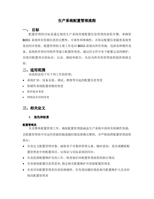
生产系统配置管理流程一、目标配置管理的目标是通过规范生产系统资源配置信息管理的流程步骤,来确保BOSS系统所有资源信息的完整性、可靠性和准确性,并保证配置信息随着系统变更而同步更新。
配置管理的主要工作是对BOSS系统内所有资源,包括各种硬件设备、系统软件和应用软件等建立配置管理表,通过对文件中各个配置记录的维护,实现对配置项目的标识、记录、跟踪和报告,从而为所有的管理流程提供基础支持。
二、适用范围该流程适用于对下列工作的管理:•系统扩容、设备安装、调试、维修等引起的配置信息变更•软硬件系统配置参数的变更•软件版本变更•网络拓扑结构变更三、相关定义1.角色和职责配置管理员负责整体配置管理工作,确保配置管理能涵盖生产系统中的所有软硬件资源,且配置管理表中对这些资源的描述随时都是准确完整的,并严格按照配置管理流程执行:•负责定义配置管理对象,抽取各个对象的管理元素,随时添加、更改或删除配置管理表中的配置项目,以保证与实际系统的同步。
•负责监督配置维护员的工作,检查他们对配置管理流程的执行情况•负责接收配置信息变更单, 指定相关配置维护员更新配置管理表.•负责评估配置管理表信息的准确性,在发现问题时敦促相关配置维护人员及时修改配置管理表•负责在配置管理表修改完毕并核查无误后,对其进行备份。
●维护配置变更汇总表,将每次的配置信息变更行为记录在册。
配置维护员根据配置管理表中定义的配置管理项目,收集系统数据,建立初始配置信息,并随着各种变更的发生而及时更新配置管理表的相关信息。
●收集所管辖资源的初始配置信息●检查配置信息的准确性●将核查正确的配置信息写入配置管理表●在发生变更前,备份系统配置文件和参数文件。
●接收配置管理员发送的配置变更单,据此修改配置管理表中的相关项。
配置维护员可根据管理资源的种类划分为:-主机和存储设备配置维护员-数据库配置维护员-网络配置维护员(包括对网络设备、软件、网络拓扑、IP地址分配等配置信息)-应用软件配置维护员(含开发工具)-外围设备配置维护员(包括微机、打印机等非关键设备的软硬件配置)2.配置管理对象配置管理所涉及的资源,主要包括:-主机-数据库-磁盘阵列、磁带库-网络设备-应用软件-外围设备3.配置管理项目各配置管理对象需记录的具体配置参数项,例如主机的名称、IP地址、CPU型号和数量、内存量、操作系统版本号等。
- 1、下载文档前请自行甄别文档内容的完整性,平台不提供额外的编辑、内容补充、找答案等附加服务。
- 2、"仅部分预览"的文档,不可在线预览部分如存在完整性等问题,可反馈申请退款(可完整预览的文档不适用该条件!)。
- 3、如文档侵犯您的权益,请联系客服反馈,我们会尽快为您处理(人工客服工作时间:9:00-18:30)。
仪器无关测试系统IVI配置文件的管理(转载)( 更新时间:2006-08-31 16:15:08)1概述VPP规范中定义了VISA(virtualinstrumentsoftwarearchitecture)接口软件,对串行总线、GPIB总线、VXI总线仪器的操作提供了统一接口,提高了仪器的可互换性。
19 9 8年8月,为了进一步提高仪器驱动程序的执行性能,达到真正的仪器互换性,由9个公司成立IVI(InterchangeableVirtualInstrumentation)基金会,在VPP的基础上为仪器驱动程序制定新的编程接口标准,使应用程序可以实现完全独立于硬件,而不管其是何种总线接口,并增加了仪器仿真、状态缓存等机制,使仪器执行效率大大提高。
2IVI系统结构目前,IVI基金会共规范和开发了5类驱动程序:示波器、数字多用表、任意波形/函数发生器、开关和直流电源。
即将推出射频信号发生器、频谱分析仪、功率计、数字仪器分类驱动程序。
IVI系统结构如图1所示,由IVI分类驱动程序、IVI具体仪器驱动程序、IVI引擎、IVI配置实用程序、IVI配置信息文件5部分组成。
应用测试程序中调用分类驱动程序,分类驱动程序调用具体仪器驱动程序来控制实际的仪器,因此,即使测试系统的具体仪器改变,也不会使分类驱动程序的测试代码受到影响。
2 1分类驱动程序一个分类驱动程序是一组仪器无关函数和属性用于控制某一类型的仪器,比如示波器、数字多用表、函数发生器等,这些函数有一个通用功能前缀如IviScope、IviDmm或IviFgen。
目前IVI驱动程序工具箱共有5类:示波器、数字多用表、任意波形/函数发生器、开关和电源,每个分类驱动程序调用具体仪器驱动程序来控制实际的仪器。
因为每一类中的所有仪器不可能具有完全相同的功能和性能,没有一个单一的编程接口可以适用于所有的仪器,因此IVI分类驱动程序将仪器能力分为固有的IVI能力、基本能力、扩展组能力、仪器特有的能力4种。
固有的IVI能力是指所有的IVI分类驱动程序都具有的函数和属性,比如ClassPrefix- init( )函数,对5类驱动程序而言,只是将ClassPrefix(类前缀)加上,分别为IviScope、IviDmm、IviDCPwr、IviFgen或IviSwtch,此类函数有19个;基本能力是指某类仪器公有的函数和属性,可以覆盖某类仪器95 %以上的功能,例如示波器的基本功能为:沿触发采集、初始化一个采集过程、返回采集波形等,一个IVI兼容的仪器必须具有上述基本能力;扩充组功能(ExtensionGroups)是指并不是某一类仪器都具有的、更为特殊的函数和属性组,具体仪器驱动程序不需要实现扩充功能组,由IVI分类驱动程序为属于某类仪器不标准的功能创建标准编程接口,例如,虽然所有示波器水平和垂直设置都有相同的基本功能,但却有各种各样的触发模式,IviScope分类驱动程序包含了不同触发模式的扩展功能,比如TV触发、runt触发、宽度触发等等,每个具有TV触发的示波器都能遵守IviScope分类驱动程序的TV触发扩展组函数和属性。
仪特有的功能是指其他设备没有的,为了使用这些功能必须在程序中直接访问IVI具体驱动程序,这部分程序将不支持仪器互换性。
2 2具体仪器驱动程序具体仪器驱动程序包含控制一个特定仪器的信息,包括命令串、分析代码、每个设置的正确量程等。
其对外接口与VISA仪器驱动程序没有什么区别,但内部实现方法却大不相同,在VPP基础上增加了仪器仿真、状态缓存、量程检查等功能。
2 3IVI引擎IVI引擎完成状态缓存、仪器属性跟踪、分类驱动程序到具体驱动程序的映射功能。
是实现IVI仪器驱动程序完成状态缓存和其他增强性能的关键支持库,比如仪器仿真、量程检查和状况检查等功能。
在开发期间,这些功能可以辅助应用软件的调试与开发,一旦转入产品模式,IVI引擎允许关闭量程检查、状况检查、仪器仿真等功能,以获得最快速度的软件执行性能。
2 4IVI配置实用程序IVI系统提供了名为“Measurement&AutomationeXplorer”(简称MAX)的IVI配置程序,用于配置仪器无关测试系统,创建和配置IVI逻辑名称(logicalnames) ,在测试程序中通过传送逻辑名称给一个分类驱动程序初始化函数,以将操作映射到具体仪器及其仪器驱动程序。
2 5IVI配置信息文件通过MAX创建和配置的信息保存在Vxipnpwin9 5niiviiviini文件中,该文件存储了所有逻辑名称和分类驱动程序到具体仪器驱动程序的映射信息。
3硬件无关性的实现过程如图2所示,在应用软件中通过逻辑名称调用分类驱动程序,IVI引擎通过逻辑名称检查IVI配置文件,以确定正在使用的具体仪器,并动态地调用具体仪器驱动程序相应的初始化函数,与仪器建立会话连接,并将会话句柄返回给分类驱动程序,然后,分类驱动程序其他函数通过该句柄发送仪器控制命令和接收数据,这些函数同样被IVI引擎映射到具体仪器驱动程序的函数,以完成对硬件仪器的I/O操作,通过这个过程实现了仪器的互换性。
更换了仪器之后,只要修改配置文件的信息,使程序中的逻辑名称指向新的仪器和仪器驱动程序,而应用程序不需要任何改变。
4IVI驱动程序的其他性能特征IVI驱动程序虽然是建立在VPP规范之上的标准,但不导致额外的复杂性和性能下降,而是增加了很多提高系统执行效率、缩短开发时间的特性,除硬件可互换性之外,还有以下几个方面的特性。
4 1仪器状态缓存标准的仪器驱动程序不跟踪仪器的状态,所以测量函数在实施测量前必须进行仪器状态设置,即使仪器已经被配置正确,这样的过程必然会引入多余的仪器I/O操作,IVI驱动程序自动缓存仪器当前状态,只有在仪器状态与函数所需要的不同时才执行仪器I/O,这种表面上小小的不同却明显缩短了测试时间,在某些情况下,执行时间甚至会减少一半。
4 2量程检查及参数强制驱动程序包含仪器每个属性的量程表,保存属性的正确值,引擎利用量程表校验用户设置的值是否在有效量程之内。
量程检查包含一种强制属性,是指落入某一指定范围的值强制为一指定值,比如,示波器的水平时基落入秒和纳秒之间值只能以1x、2x和5x递增,而不能出现3x等,在发送值到仪器之前,强制量程表自动强制任何值为适当值,比如强制4x为5x。
4 3仪器仿真当仪器不存在时,IVI驱动程序可以仿真仪器的操作,并返回仿真数据。
如果允许仿真,IVI驱动程序不执行仪器I/O,而为输出参数创建仿真数据。
通过仿真数据,即使在没有仪器的情况下开发者也可以开发测试系统软件代码。
4 4多线程安全性IVI驱动程序是在LabWindows/CVI5.0环境中开发的,支持多线程,多个执行线程可以用相同的IVI仪器会话,而不会互相影响,所以可以用于高水平的、多线程并行测试系统。
4 5可配置的状态检查功能在每次操作之后,程序自动查询仪器的状况是否正常,该功能可以在软件调试完毕后关闭。
5IVI配置文件信息结构IVI系统配置信息存储在Vxipnpwin9 5 niiviiviini文件中,一般通过MAX工具可以进行交互式修改和配置,也可以通过文本编辑软件修改和查看。
5.1配置文件信息配置文件信息分为4个信息区,并具有较好的层次性。
( 1) [IviLogicalNames] :本区信息指定逻辑名称对应的虚拟仪器名称,格式:LOGICAL- NAME=“VInstr- >virtualinstrumentname”,例如:dmm1=“VInstr- >hpe1411b” ;( 2) [LogicalName- >somelogicalname] :定义一个逻辑名称必须链接到的虚拟仪器;参数:Description=描述逻辑名称;( 3) [Class- >someclass] :定义一个类和相应的分类仿真虚拟仪器;参数:Description=类描述。
SimulationVInstr=指向被类仿真使用的仿真虚拟仪器;( 4) [VInstr- >somevinstr] :定义和配置虚拟仪器参数:Cache=是否允许状态缓存(True/False)RangeCheck=是否允许量程检查(T/F)QueryInstrStatus=是否允许状况查询(T/F)RecordCoercions=是否允许强制情况记录(T/F)InterchangeCheck=是否允许互换性检查(T/F)Spy=是否允许NI-Spy(跟踪所有VISA、IVI、48 8.2函数调用的实用程序)支持(T/F) Simulate=是否允许仿真(T/F)UseSpecificSimulation=是否使用指定的仿真驱动程序(T/F)IsSimulationVInstr=是不是一个仿真虚拟仪器(T/F)Driver=相应驱动程序区[Driver- >somedriver]Hardware=相应硬件区[Hardware- >somehardware]DefaultSetup=相应的[DefaultSetup- >somesetup]区VirtualChannelNames=定义硬件无关的通道名称( 5) [Driver- >somedriver] :定义和配置一个驱动程序文件(driverdll)。
参数:Description=描述一个具体仪器驱动程序ModulePath=驱动程序路径,如果路径缺省则设定为C:VXIPNPWINxxBINPrefix=在驱动程序中使用的函数前缀Interface=例如GPIB或SERIAL等Class=指明驱动程序所依附的IVI类IsSimulationDriver=是否是一个仿真驱动程序(T/F)( 6) [DefaultSetup- >somesetup] :用于启动时传送属性值到一个仪器驱动程序格式:ATTRIBUTE=值( 7) [Hardware- >somehardware] :描述一个仪器的物理位置参数:Description=硬件接口描述ResourceDesc=正确的VISA资源字串,例如“GPIB::1::INSTR” ,仪器驱动程序通过该名称找到硬件仪器。
5.2 配置文件实例在下面的实例中,SCOPE1逻辑名称指向hp548xx示波器(实际用的是hp54815) ,IVI引擎通过图3所示的层次结构将逻辑名称指向具体的硬件仪器。
[IviLogicalNames]SCOPE1=″VInstr->hp548xx″power=″VInstr->hp6610xa″dmm1=″VInstr->hpe1411b″[VInstr->hp548xx]IsSimulationVInstr=FalseDriver=Driver->hp548xxDescription=Hewlett-Packard548xxOscilloscopeCache=TrueRangeCheck=TrueQueryInstrStatus=TrueRecordCoercions=FalseUseSpecificSimulation=FalseSpy=TrueInterchangeCheck=FalseSimulate=TrueHardware=″Hardware->hp548xx″VirtualChannelNames=″CHANNEL1=CHAN1,CHANNEL2=CHAN2″[Driver->hp548xx]Description=Hewlett-Packard548xxOscilloscopeModulePath=hp548xx_32.dllPrefix=hp548xxInterface=GPIBClass=IviScopeIsSimulationDriver=False[Hardware->hp548xx]ResourceDesc=″ASRL1::INSTR″Description=″hp5 48xxOscilloscope″[VInstr->hpe1428a]IsSimulationVInstr=False...VirtualChannelNames=″CHANNEL1=CHAN1,CHANNEL2=CHAN2″[Driver->hpe1428a]ModulePath=hpe1428a_32 dll...Interface=VXI[LogicalName->SCOPE1]Description=″HPOSC″文件中包含了hpe1428a和hp5 48xx两台示波器的信息,此时的逻辑名称SCOPE1对应hp5 48xx示波器,当系统将hp5 48xx示波器换为hpe1428a时,只要改变[IviLogicalNames]区中的参数为SCOPE1=″VInstr- >hpe1428a″即可以实现SCOPE1与hpe1428a的映射,应用程序不需要做任何改变,实现了仪器无关性设计。