pisco节流阀
CONFLOW 阀门
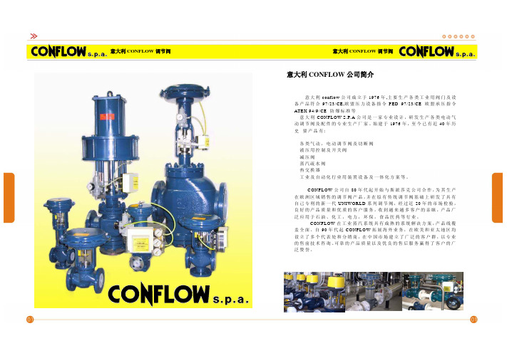
EN 标准阀体 适用于气体、水、 油品及其它介质 等 百/线 性/快 开 适 用 温 度 : -5 ℃ -350℃ DN15-DN100 PN40
52000 系 列 单 座 两通控制阀
EN 标准紧凑型阀体 单笼或双阀笼 平衡或非平衡式阀芯 适用介质:水、蒸汽、气 体、油品等 适 用温度: -5℃ -+350℃ DN15-DN100 PN40
52/3/400 系 列 单 座两通控制阀
紧凑型阀体结构 合流或分流功能 多种阀体材质可选 阀件可按需选择 用 于 热 交 换 系 统 ,冷 凝系统或导热油等 DN15-DN100 PN40
56/5700 系 列 单 座两通控制阀
ANSI 标准阀体结构 适用于大流量高压 差场合 配带多弹簧执行器 口 径 : 2”-8” CLASS 150/300
,,,,,,,,,,,,,,,,,,,,,,,,,,,,,,,,,,,,,,,,,,,,,,,,,,,,,,,,,,,,,,,,,,,,,,,,,,,,,,,,,,,,,,,,,,,,,,,,,,,,,,,,,,,,, ,,,,,,,,,,,,,,,,,,,,,,,,,,,,,,,,,,,,,,,,,,,,,,,,,,,,,,,,,,,,,,,,,,,,,,,,,,,,,,,,,,,,,,,,,,,,,,,,,,,,,,,,,,,,, ,,,,,,,,,,,,,,,,,,,,,,,,,,,,,,,,,,,,,,,,,,,,,,,,,,,,,,,,,,,,,,,,,,,,,,,
ANSI 标准紧凑型阀体 单笼或双阀笼 平衡或非平衡式阀芯 适用介质:水、蒸汽、气 体、油品等 适 用温度: -5℃ -+350℃ 1/2”-8” CLASS 300
ANSI 标准阀体结构 合流或分流功能 多种阀体材质可选 阀件可按需选择 用 于 热 交 换 系 统 ,冷 凝系统或导热油等
费斯托比例压力调节器VEAA系列说明书

Proportional-pressure regulators VEAA2d Internet: /catalogue/...Subject to change – 2022/03Proportional-pressure regulators VEAAKey featuresInnovative FlexibleOperational safetyEasy to install• Silent operation• Very low power consumption • Extremely precise•Integrated piezo technology• In-line valves • Sub-base valves• Simple electrical and pneumatic interfaces• Choice of different setpoint specifications – Current input – Voltage input• Integrated pressure sensor with separate output • Diagnostics:– Operating voltage: over- and undervoltage– Setpoint value: falling below and exceeding• Consistent pressure regulation performance with long-term stability• Mounting the in-line valve via three lateral through-holes • H-rail mounting• Mounting the in-line valve on the mounting plate• Mounting the sub-base valve using the sub-baseProportional-pressure regulators VEAA Key features[1] Power LED (green), fault LED (red)[2] Electrical connection,M8 plug[3] Through-holes for mounting thevalve on the sub-base[4] Port 2, working air[5] Port 3, exhaust air[6] Port 1, compressed air3 2022/03 – Subject to change d Internet: /catalogue/...Proportional-pressure regulators VEAAKey features1located on the manifold rail.4d Internet: /catalogue/...Subject to change – 2022/03Proportional-pressure regulators VEAA Product range overview5 2022/03 – Subject to change d Internet: /catalogue/...Proportional-pressure regulators VEAAPeripherals overviewValve manifold assembly VEAA6d Internet: /catalogue/...Subject to change – 2022/03Proportional-pressure regulators VEAAType codes72022/03 – Subject to change d Internet: /catalogue/...Proportional-pressure regulators VEAA Datasheet-M-Flow rate7 ... 13 l/min -P- Voltage24 V DC -L-Output pressure 2 (pressureregulation range)0.001 ... 0.2 MPa0.003 ... 0.6 MPa0.005 ... 1 MPaVEAA-BH--NoteSafety position, VEAA:If the electrical power supply fails,the output pressure will be unregu-lated and may rise or fall – valveblocked.8d Internet: /catalogue/...Subject to change – 2022/0392022/03 – Subject to changed Internet: /catalogue/...Proportional-pressure regulators VEAADatasheet1)Input pressure 1 should always be 1 bar greater than the maximum regulated output pressure.2)Corrosion resistance class CRC 2 to Festo standard FN 940070Moderate corrosion stress. Indoor applications in which condensation can occur. External visible parts with primarily decorative surface requirements which are in direct contact with a normal industrial environment.3)For information about the area of use, see the EC declaration of conformity at:: /catalogue/... d Support/Downloads.If the devices are subject to usage restrictions in residential, commercial or light-industrial environments, further measures for the reduction of the emitted interference may be necessary.FunctionAn integrated pressure sensor records the pressure at the working port and compares this value with the setpoint value.The pressure is automaticallyreadjusted in the event of deviations.Proportional-pressure regulators VEAADatasheet10d Internet: /catalogue/...Subject to change – 2022/03Proportional-pressure regulators VEAA Datasheet11 2022/03 – Subject to change d Internet: /catalogue/...Proportional-pressure regulators VEAADatasheet12d Internet: /catalogue/...Subject to change – 2022/03Proportional-pressure regulators VEAA Datasheet13 2022/03 – Subject to change d Internet: /catalogue/...Proportional-pressure regulators VEAADatasheet14d Internet: /catalogue/...Subject to change – 2022/03Proportional-pressure regulators VEAA Datasheet15 2022/03 – Subject to change d Internet: /catalogue/...Proportional-pressure regulators VEAADatasheet16d Internet: /catalogue/...Subject to change – 2022/03Proportional-pressure regulators VEAA Datasheet17 2022/03 – Subject to change d Internet: /catalogue/...Proportional-pressure regulators VEAADatasheet18d Internet: /catalogue/...Subject to change – 2022/03Proportional-pressure regulators VEAA Accessories19 2022/03 – Subject to change d Internet: /catalogue/...Festo - Your Partner in AutomationConnect with us/socialmedia 1Festo Inc.2Festo Pneumatic 3Festo Corporation 4Regional Service Center 5300 Explorer DriveMississauga, ON L4W 5G4CanadaAv. Ceylán 3,Col. Tequesquináhuac 54020 Tlalnepantla, Estado de México1377 Motor Parkway Suite 310Islandia, NY 117497777 Columbia Road Mason, OH 45040Festo Customer Interaction CenterTel:187****3786Fax:187****3786Email:*****************************Multinational Contact Center 01 800 337 8669***********************Festo Customer Interaction Center180****3786180****3786*****************************S u b j e c t t o c h a n g e。
Festo VTSA(-F)-FB(-NPT) 产品说明书
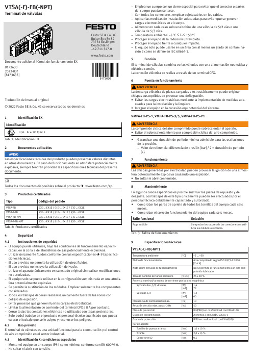
1Identificación EX2Documentos aplicables3Productos certificados4Seguridad4.1Instrucciones de seguridad–El equipo puede utilizarse, bajo las condiciones de funcionamiento especifi-cadas, en la zona 2 de atmósferas de gas potencialmente explosivas.–Utilizar únicamente fluidos conforme con las especificaciones è 9 Especifica-ciones técnicas.–El uso previsto no permite la utilización de otros fluidos.–El uso previsto no incluye la utilización del vacío.–Utilizar el aparato únicamente en su estado original sin realizar modificaciones no autorizadas.–El equipo solo se puede utilizar en la configuración suministrada en una atmós-fera potencialmente explosiva.–Se permite la sustitución de los módulos. Emplear solamente los componentes considerados.–Todos los trabajos deberán realizarse únicamente fuera de las zonas con peligro de explosión.–Evitar procesos que generen fuertes cargas electrostáticas.–Limitar la alimentación de corriente del terminal CPX a 8 A por contacto.–Cerrar todas las conexiones eléctricas no utilizadas con tapas protectoras.–Solo podrá trabajar en el producto el personal técnico cualificado que pueda valorar el trabajo que se le asigne y reconocer los peligros.4.2Uso previstoEl terminal de válvulas es una unidad funcional para la conmutación y el control de aire comprimido en el sector industrial.4.3Identificación X: condiciones especiales–Montar el equipo en un cuerpo IP54 como mínimo, conforme con EN 60079-0.–No soltar ni abrir con tensión.–Emplear un cuerpo con un cierre especial para evitar que el conector o partes del cuerpo puedan soltarse.–Con todos los conectores, emplear sujetacables en los cables.–Aplicar las medidas de instalación adecuadas para evitar que se generen cargas electrostáticas en el cuerpo.–Alimentar en cada caso solo una bobina de una válvula de 5/2 vías o una válvula de 5/3 vías.–Temperatura ambiente: –5 °C £ T a £ +50 °C –Proteger el equipo de la radiación ultravioleta.–Proteger el equipo frente a cualquier impacto.–El equipo solo puede usarse en un área con al menos un grado de contamina-ción 2 como se define en IEC 60664-1.5FunciónEl terminal de válvulas combina varias válvulas con una alimentación neumática y eléctrica común.La conexión eléctrica se realiza a través de un terminal CPX.6Puesta en funcionamientoVMPA-FB-PS-1, VMPA-FB-PS-3/5, VMPA-FB-PS-P1•Garantizar una duración de período mínima admisible para las oscilaciones de la presión.–Valor de referencia: diferencia de presión [bar] / 2 = duración de periodo [s].7Funcionamiento8MantenimientoEn algunos casos específicos es posible sustituir las piezas de repuesto y de desgaste. Los trabajos de este tipo únicamente pueden ser efectuados por el personal técnico debidamente capacitado y autorizado.•Comprobar los pares de apriete de todos los tornillos del cuerpo cada seismeses.•Comprobar el correcto funcionamiento del equipo cada seis meses.9Especificaciones técnicas。
cashco调节阀1164
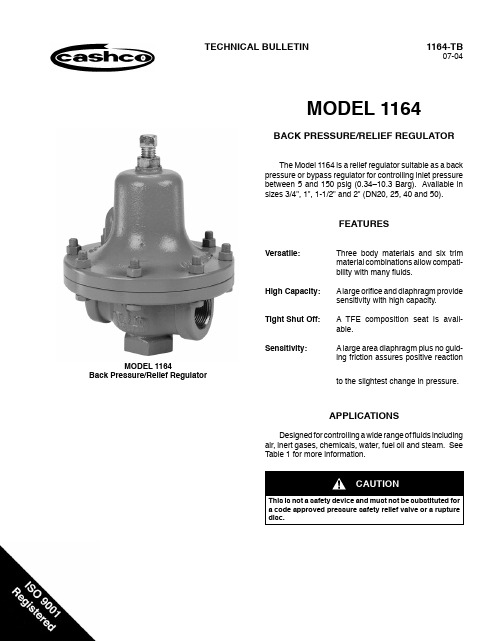
1164-TB07-04TECHNICAL BULLETINMODEL 1164BACK PRESSURE/RELIEF REGULATORThe Model 1164 is a relief regulator suitable as a backpressure or bypass regulator for controlling inlet pres s urebetween 5 and 150 psig (0.34–10.3 Barg). Avail a ble insizes 3/4", 1", 1-1/2" and 2" (DN20, 25, 40 and 50).FEATURESVersatile: Three body materials and six trimmaterial combinations allow com p at i-bil i t y with many fl uids.High Capacity: A large orifi ce and diaphragm pro v idesensitivity with high capacity.Tight Shut Off: A TFE composition seat is avail-a ble.Sensitivity: A large area diaphragm plus no guid-i ng friction assures positive re a c t ionto the slightest change in pressure.APPLICATIONSDesigned for controlling a wide range of fl uids in c lud i ngair, inert gases, chemicals, water, fuel oil and steam. SeeTable 1 for more in f or m a t ion.MODEL 1164Back Pressure/Relief RegulatorCAUTIONThis is not a safety device and must not be substituted for21164-TBSTANDARD/GENERAL SPEC I F I C A T IONSBody Sizes:End Connections:Body/Spring Chamber MaterialCombinations:Inlet Pressure:Trim Designs:3/4", 1", 1-1/2" and 2".(DN20, 25, 40 and 50).NPT female only.CI/CI, CS/CS, CS/CI, BRZ/BRZ* andBRZ/CI*.CI = Cast grey iron CS = Cast carbon steel BRZ = Cast bronze*Not available in sizes 1-1/2" & 2"(DN40, 50). See Table 3 for ma t e -ri a ls speci fi cations.Temperature:Capacities:Gaskets:Range Springs:Model 1164Metal SeatModel 1164Composition SeatStandard:CI: -20° to +350°F (-29° to +177°C)BRZ & CS: -20° to +400°F (-29° to +205°C)See Tables 2 and 3.Up to 15.7 Cv; See Table 4 for Cv vs. set pressure vs. body size.Water fl ow – See Table pressed air fl ow – See Table 6.Steam fl ow – See Table 7.Capacities are for 10, 20, 30, 40 and 50 percent buildup over set pressure. Set pressures are made with a fl ow of 2% or less of the 20% build up ca p ac i t ies.Example: 100 psig (6.89 Barg) set pressure and a 30% build up = 130 psig (8.96 Barg) fl owing pressure for the capacity listed.Standard: Non-asbestos; Aramid/SBR.NOT SUITABLE FOR OXYGEN SERVICE.Alternate –See Option -45.Standard: Epoxy coated steel.Body MaterialMax. Pressure psig (Barg)CI 175(12.1)BRZ 200(13.8)CS225(15.5)See Table 3.Metal seated or com p o s i t ion seated with metal diaphragm. See Table 2.* See Table 3 for limitations forCI/CI/XX, BRZ/CI/XX and CS/CI/XX ma t e r i a ls P vs T rat i ng.Range Springs psig (Barg)5–15(.34–1.03)10–40(0.69–2.8)30–80(2.1–5.5)70–150 *(4.8–10.3)1164-TB 3OPTION SPECIFICATIONSOption-25: TAPPED VENT. 1/4" NPT tappedopen i ng in spring cham b er for piping vent to re m ote location in the event of di a p hragm failure. Available on CI and CS spring cham b ers only.Option-45: NON-ASBESTOS GASKETS. For ox- y g en ser v ice. Uti l iz e s TFE di a p hragm gasket over stan d ard gas k ets. Tem- p er a t ure range; -20° to +400°F (-29° to +205°C).Option-55: SPECIAL CLEANING. BRZ bodymaterial only. Clean i ng per Cashco Speci fi cation #S-1134. AcceptableAPPLICATION AND SELECTIONCon s id e r level of pres s ure build tobe added (Step 3 below).STEP 3. PRESSURE BUILD. Once setpoint isreached and valve opens, all self-con-tained back pres s ure/relief reg u l a t ors “build” from a setpoint pressure level as the fl ow rate increases. This deviation in setpoint is de s cribed as “% build”. Build is expressed on in c reas i ng fl ow, starting from a min- i m um fl ow level. The “% build”, or stated max i m um al- l ow a ble build, must be known to en t er the ca p ac i t y tables. The ac c ept a ble level of setpoint de v i a t ion should be known for the min-to-max fl ow vari- a t ion.The following procedure will help de t er m ine a suitable selection for an application.STEP 1. FIVE KNOWNS. The following min- i m al pa r am e t ers/in f or m a t ion must beavail a ble before a se l ec t ion pro c e d ure can be g in:a. Service Fluid – What is it? Liq u id or gas? SG (Std. cond.).b. Inlet Pressure – P 1 (upstream pressure). How much can P 1 vary as fl ow varies?”c. Outlet Pressure – P 2 (down-s tream pressure).d. Desired ca p ac i t y – Cv, GPM, SCFH; min i m um and max- i m um.e. Fluid tem p er a t ure – T 1, SG (ac t u a l).STEP 2. INLET PRESSURE. Ensure that the ac t u a l design inlet pressure and tem p er a t ure limits do not exceed the lim i ts established in T able 3. Both body and spring cham b er must comply.Standard: CI and CS – Enamel per Cash c o Spec #S-1545. BRZ – Non-painted.Alternate: See Opt-95.Standard: Cadmium or zinc plated, heat treated steel.clean i ng level for oxygen gas service.Use for non-cryo g en i c ser v ice.Option-56: SPECIAL CLEANING. CI or CS body materials only. Clean i ng per Cashco Spec i fi c a t ion #S-1542. Not suitable for oxygen service. Use for non-cryo g en i c ser v ice.Option-95: EPOXY PAINTED. Two-step epoxy coated for se v ere ambient conditions to minimize ex t er n al corrosion. A p p lied to all ex p osed parts. Procedures and specs per Cashco Spec #S-1547.Flange Bolting:Painting:TABLE 1APPLICATIONSFluid Recommended Construction Trim #Air or Inert Gases TFE Seat and Metal Diaphragm S5, S9 or S36ChemicalsMetal Seat and Diaphragm S0 or S1 TFE Seat and Metal Diaphragm S9, or S36Fuel Oil ‡TFE Seat and Metal Diaphragm S36 Hydrocarbon Gas or Liquids ‡TFE Seat and Metal Diaphragm S36 Steam, Saturated or Superheated Metal Seat and Diaphragm S1 or S2Water and Condensate, 32–300°F (0–149°C)TFE Seat and Metal Diaphragm S36Metal Seat and Diaphragm S1 or S2 TECHNICAL SPECIFICATIONSA regulator may have a setpoint 10%below the lower stated range springlevel. (Tags will show the standardranges.) A set p oint above the higherrange spring level is not rec o m -mend e d. Setpoint at the upper limitof a range spring is ac c ept a ble. If fi nalsetpoint is ques t ion a ble and ex p ect e dnear the upper limit, the next higherrange spring should be utilized. Bestperformance will be obtained whenthe lowest range spring is uti l ized.STEP 4. GASKET MATERIAL. Consideringthe fluid, determine desired gasketma t e r i a l from two choices offered. STEP 5. CAPACITY. The fi ve knowns of Step1 allow proper sizing of the regulator.(Specifi c gravity tables are required.)With P1, P2, % build, flow rate (Cv,GPM, SCFH or #/HR), enter the ca-p ac i t y tables and confi rm Model 1164ca p a b il i t y.Refer to Tables 4 through 7 for ca-p ac i t ies.STEP 6. TRIM MATERIAL. Use of Table 1 andT able 2 allows proper se l ec t ion of “TrimDes i g n a t ion Num b ers” for ma t e r i a lsand temperatures. See Table 1 fortype of service and rec o m m end e dcon s truc t ion.A composition seat will initially pro v idebubble-tight shutoff in clean ser v iceand without upstream over-pres s ur -iza t ion. Minute leakage should be ex-p ect ed with metal seated designs.NOTE 2: Cashco, Inc. does not recommend metal seat e d trim on any service where the fl ow will be dead ended down stream of the pres s ure reducing regulator.‡ In accordance with ASME B31.3 “process piping”, do not use Cast Iron Body for hydrocarbon or fl ammable fl uidservice with inlet pres s ures greater than 150 psig (10.3 Barg) or temperatures greater than 300° F (149° C).41164-TBTABLE 2STAINLESS STEEL TRIM MATERIAL COM B I N A T IONSPart S0S1S2 1S5S9S36Diaphragm TFE Coated302 SST 302 SST302 SST PhosphorBronzeTFE Coated302 SST302 SSTPlug316 SST316 SST416 SST316 SST316 SST316 SST Seat Ring316 SST316 SST316 SST316 SST316 SST316 SST Seat O-ring NONE NONE NONE TFE TFE TFE Plug Spring302 SST302 SST302 SST302 SST302 SST302 SSTTemperature Range-20 – +400°F(-29 – +205°C)-20 – +400°F(-29 – +205°C)-20 – +400°F(-29 – +205°C)-20 – +400°F(-29 – +205°C)-20 – +400°F(-29 – +205°C)-20 – +400°F(-29 – +205°C)TABLE 3MAXIMUM PRESSURE/TEMPERATURE RATINGSSTANDARD CONSTRUCTIONSMaterial Specifi cations(Body/Spring Chamber)InletDescriptionAbbr.ASTM No.Pressure Temperaturepsig(Barg)°F°CCI/CI A126, Class B175165150140125(12.1)(11.4)(10.3)(9.7)(8.6)-20 to +150-20 to +200-20 to +250-20 to +300-20 to +350(-29 to +65.9)(-29 to +93.7)(-29 to +121.4)(-29 to +149.2)(-29 to +177)BRZ/CI1B62, Alloy C83600/ A126, Class BCS/CI A216, Gr. WCB/ A126, Class BBRZ/BRZ1B62, Alloy C83600200(13.8)-20 to +400(-29 to +205)CS/CS A216, Gr. WCB225(15.5)-20 to +400(-29 to +205)TABLE 4Cv FOR SET PRESSURE PLUS PRESSURE BUILD UP(F L = 0.945)1 Not available in Bronze bodies; only Iron or Steel bodies.Set Pressurepsig3/4" & 1" BodyPressure Build-up over Set Pressure1-1/2" & 2" BodyPressure Build-up over Set Pressure 10%20%30%40%50%10%20%30%40%50%5.88 1.55 2.11 2.61 2.96 1.62 2.98 4.12 5.076.0410 1.11 1.93 2.60 3.17 3.60 2.56 4.29 5.757.098.3615 1.33 2.31 3.09 3.72 4.24 3.46 5.617.399.0910.625 1.20 2.01 2.68 3.30 3.86 3.53 5.22 6.918.4010.135 1.50 2.45 3.24 3.95 4.66 4.63 6.738.7610.812.850 1.17 1.97 2.71 3.35 3.91 3.93 5.767.419.1610.975 1.63 2.77 3.77 4.60 5.44 5.397.8210.112.514.7100 1.52 2.75 3.72 4.67 5.68 5.307.519.3911.413.4150 2.24 3.75 4.95 6.637.95 6.399.0211.313.515.71 1-1/2" - 2" not available in BRZ material.1164-TB561164-TBTABLE 5WATER CAPACITY IN GPM 1S.G. = 1.0 T = 60°F F L = 0.945(Outlet Pressure is Atmosphere)1 Many of the above capacities meet or exceed the velocities recommended for piping. Use reducers and larger pipe to reduce thevelocities to acceptable limits.NOTE: Flow capacities in shaded areas within the above table indicate that the water has reached full cavitation, and the flow is choked.TABLE 6AIR CAPACITY IN SCFHS.G. = 1.0 T = 60°F F L = 0.945(Outlet Pressure is Atmosphere)NOTES: 1. Flow capacities in shaded areas within above table indicate that fl ow has reached or exceeded a velocity of Mach 0.35, an accepted limit for expanded air on the downstream side. Use of higher velocities normally generate high noise levels.2. Where “SONIC” is indicated within the above table, outlet velocity with Schedule 40 pipe has reached sonic velocity of 1118 fps. Addi-tional fl ow can not be obtained, and pipeline velocity is in excess of customary pipe velocity design limits. Flow will be approximately the last indicated value in the column above “SONIC”.1164-TB7TABLE 7STEAM CAPACITY IN LBS/HRS.G. = Actual T = Saturated F L = 0.945(Outlet Pressure is Atmosphere)NOTES: 1. Flow capacities in shaded areas within above table indicate that fl ow has reached or exceeded a velocity of Mach 0.35, an accepted limit for expanded steam on the downstream side. Use of higher velocities normally generate high noise levels.2. Where “SONIC” is indicated within the above table, outlet velocity with Schedule 40 pipe has reached sonic velocity of 1118 fps. Ad-ditional fl ow can not be obtained, and pipeline velocity is in excess of customary pipe velocity design limits. Flow will be approximately the last indicated value in the column above “SONIC”.81164-TB1164-TB 9Body Size ENGLISH UNITS - Inch & Lbs.A B C D Ship Wt.3/4" and 1" 5.137 1.947181-1/2" and 2"6.9192.889.6337Body Size METRIC UNITS - mm & kgA B C D Ship Wt.DN20 and 25130178491788.17DN40 and 501752297324416.79DIMENSIONS & WEIGHTSNOTES101164-TBNOTES1164-TB11PRODUCT CODE 02/13/04Cashco, Inc.P.O. Box 6Ellsworth, KS 67439-0006PH (785) 472-4461Fax (785) 472-3539E-mail: sales@exportsales@Printed in U.S.A. 1164-TB。
PISCO管接头
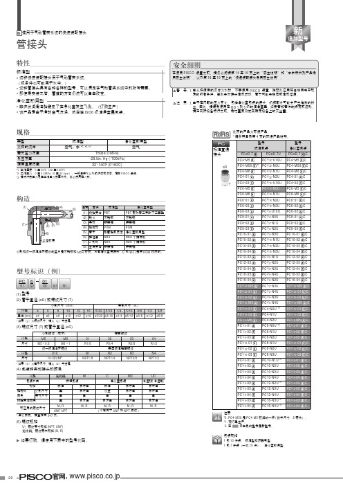
PV12
PV3/8
PV12 C
PV3/8 C
PPF16
PPF3/8
PPF16 C PPF3/8 C
PV16
PV1/2
PV16 C
PV1/2 C
PPF1/2
PPF1/2 C
PL
L 形弯头
øD T
型号
标准包装
PLøD-T
PLøD-TU
PL4-M5
PL5/32-U10U
PL4-M6
PL5/32-N0U
PL4-01
统一标准细牙螺纹
代码 尺寸
U10 10-32UNF
* 如果(3)为管子尺寸,请从(2)中选择。
(4) 包装种类和接头的颜色
N1 NPT1/8
代码
包装分类
规格
释放环
公制尺寸
颜色
英寸尺寸
树脂壳体颜色
无代码
W
标准包装
标准
象牙白
黑
象牙白
白
白
黑
象牙白
美国标准锥管螺纹
N2
N3
NPT1/4
NPT3/8
N4 NPT1/2
新
追加型号
安全细则
在使用 PISCO 装置之前,请务必阅读第 14 至 16 页上的“安全说明”和“本手册所列产品通 用安全说明”,以及第 18 至 19 页上的“快速装配接头通用安全说明”。
警 告:1. 当允许使用的流体为水时,不要使用 PISCO 装置,除非此应用符合说明书中规 定的所有条件。否则会对接头造成损坏,管子可能会脱落或造成泄漏。
镀镍铜 POM
(8)
(5) 管子
聚氨酯或尼龙 净化室即用型
铄
PC6-02 PC6-03 PC8-01 PC8-02 PC8-03 PC10-01
气缸与磁性开关知识总结——【机械设计 精品资源】
气缸知识汇总-磁性传感器知识普及Wang2014/12/31本文件简单介绍了气缸的基础知识,以便员工能更好地了解传感器如何应用在气缸上。
目录名词解释 (2)气动(PNEUMATIC) (2)气缸定义 (2)执行元件 (2)空压系统 (2)空压系统示意图 (2)空压系统的构成 (3)气缸的原理 (3)普通气缸 (3)磁性开关气缸的结构和工作原理 (4)汽缸的应用领域 (5)气缸知名品牌 (5)气缸的结构 (5)气缸的分类 (7)1、按尺寸分类 (7)2、按安装方式分类 (7)3、按缓冲方式分类 (8)4、按润滑方式分类 (10)5、按位置检测方式分类 (10)6、按驱动方式分类 (11)气缸的基本参数 (13)气缸的选型步骤(计算略) (14)SMC常见气缸型号表示方法 (15)SMC磁性开关 (16)有触点磁性开关 (16)无触点磁性开关 (16)气缸磁性开关问题 (17)问题:气缸不能用磁性开关限制它的行程吗? (17)结束 (18)名词解释气动(PNEUMATIC)是“气动技术”或“气压传动与控制”的简称。
气动技术是以空气压缩机为动力源,以压缩空气为工作介质,进行能量传递或信号传递的工程技术,是实现各种生产控制、自动控制的重要手段。
气缸定义引导活塞在其中进行直线往复运动的圆筒形金属机件。
工质在发动机气缸中通过膨胀将热能转化为机械能;气体在压缩机气缸中接受活塞压缩而提高压力。
涡轮机、旋转活塞式发动机等的壳体通常也称“气缸”。
气缸的应用领域:印刷(张力控制)、半导体(点焊机、芯片研磨)、自动化控制、机器人等等。
英文名:cylinder气缸将压缩空气的压力能转换为机械能,驱动机构作直线往复运动、摆动和旋转运动。
执行元件将压缩空气的压力能转换成机械能,驱动机构作直线往复运动、摆动和夹紧运动的元件称为气动执行元件。
空压系统空压系统示意图空压系统的构成气源部分:空气压缩机;后冷却器;气罐空气处理部分:过滤器、干燥器、油雾器、油雾分离器等 压力控制部分:调压阀、压力传感器等 方向控制部分:两通、三通、五通换向阀 速度控制部分:调速阀、流量开关、排气阀等 执行元件:直线气缸、摆动气缸、气爪等气缸的原理原理 : 压力空气使活塞移动,通过改变进气方向,改变活塞杆的移动方向。
针型节流阀-L21W针型节流阀

针型阀>>针型节流阀>>针型节流阀产品详细信息针型阀系列价格供用户或设计院工程项目做预算一、阀门的选型步骤1.明确阀门在设备或装置中的用途,确定阀门的工作条件:适用介质、工作压力、工作温度等等。
2.确定与阀门连接管道的公称通径和连接方式:法兰、螺纹、焊接等。
3.确定操作阀门的方式:手动、电动、电磁、气动或液动、电气联动或电液联动等。
4.根据管线输送的介质、工作压力、工作温度确定所选阀门的壳体和内件的材料:灰铸铁、可锻铸铁、球墨铸铁、碳素钢、合金钢、不锈耐酸钢、铜合金等。
5.确定阀门的型式:闸阀、截止阀、球阀、蝶阀、节流阀、安全阀、减压阀、蒸汽疏水阀、等。
6.确定阀门的参数:对于自动阀门,根据不同需要先确定允许流阻、排放能力、背压等,再确定管道的公称通径和阀座孔的直径。
7.确定所选用阀门的几何参数:结构长度、法兰连接形式及尺寸、开启和关闭后阀门高度方向的尺寸、连接的螺栓孔尺寸和数量、整个阀门外型尺寸等。
8.利用现有的资料:阀门产品目录、阀门产品样本等选型适当的阀门产品。
二、阀门的选型依据1.所选用阀门的用途、使用工况条件和操纵控制方式。
2.工作介质的性质:工作压力、工作温度、腐蚀性能,是否含有固体颗粒,介质是否有毒,是否是易燃、易爆介质,介质的黏度等等。
3.对阀门流体特性的要求:流阻、排放能力、流量特性、密封等级等等。
4.安装尺寸和外形尺寸要求:公称通径、与管道的连接方式和连接尺寸、外形尺寸或重量限制等。
⑤对阀门产品的可靠性、使用寿命和电动装置的防爆性能等的附加要求。
(在选定参数时应注意:如果阀门要用于控制目的,必须确定如下额外参数:操作方法、最大和最小流量要求、正常流动的压力降、关闭时的压力降、阀门的最大和最小进口压力。
)根据上述选型阀门的依据和步骤,合理、正确地选型阀门时还必须对各种类型阀门的内部结构进行详细了解,以便能对优先选用的阀门做出正确的抉择。
管道的最终控制是阀门。
液压机械英语

液压机械英语液压专业词汇流体传动(水力)hydraulic power液压技术(水力学)hydraulics液力技术(流体力学;水动力学)hydrodynamics 气液技术(液压气动学)hydro-pneumatics运行工况operating working conditions额定工况rated working conditions极限工况limited working conditions瞬态工况instantaneous working conditions稳态工况steady-state working conditions许用工况acceptable working conditions连续工况continuous working conditions实际工况actual working conditions效率efficiency旋转方向direction of rotation公称压力nominal pressure工作压力working pressure进口压力inlet pressure出口压力outlet pressure压降pressure drop;differential pressure背压back pressure启动压力breakout pressure充油压力charge pressure开启压力cracking pressure峰值压力peak pressure运行压力operating pressure耐压试验压力proof pressure冲击压力surge pressure静压力static pressure系统压力system pressure控制压力pilot pressure充气压力precharge pressure吸入压力suction pressure调压偏差override pressure额定压力rated pressure耗气量air consumption泄漏leakage内泄漏internal leakage外泄漏external leakage层流laminar flow紊流turbulent flow气穴(现象)cavitations流量flow rate排量displacement额定流量rated flow供给流量supply flow流量系数flow factor滞环hysterics图形符号graphical symbol液压气动元件图形符号symbols for hydraulic and pneumatic components 流体逻辑元件图形符号symbols for fluid logic devices逻辑功能图形符号symbols for logic functions回路图circuit diagram压力时间图pressure time diagram功能图function diagram循环circle自动循环automatic cycle工作循环working cycle循环速度cycling speed工步phase停止工步dwell phase工作工步working phase快进工步rapid advance phase快退工步rapid return phase频率响应frequency response重复性repeat ability复现性reproducibility漂移drift波动ripple线性度linearity线性区linear region液压锁紧hydraulic lock液压卡紧hydraulic sticking变量泵variable displacement pump泵的控制control of pump齿轮泵gear pump叶片泵vane pump柱塞泵piston pump轴向柱塞泵axial piston pump法兰安装flange mounting底座安装foot mounting液压马达(发动机,电动机)hydraulic motor刚度stiffness中位neutral position零位zero position自由位free position缸cylinder有杆端rod end无杆端rear end外伸行程extend stroke内缩行程retract stroke缓冲cushioning工作行程working stroke负载压力induced pressure输出力force实际输出力actual force单作用缸single-acting cylinder双作用缸double-acting cylinder差动缸differential cylinder伸缩缸telescopic cylinder阀valve底板sub-plate油路块manifold block板式阀sub-plate valve叠加阀sandwich(plate)valve插装阀cartridge valve滑阀slide valve锥阀poppet valve阀芯valve element阀芯位置valve element position单向阀check valve液控单向阀pilot-controlled check valve 梭阀shuttle valve压力控制阀pressure control valve溢流阀pressure relief valve顺序阀sequence valve减压阀pressure reducing valve平衡阀counterbalance valve卸荷阀unloading valve直动式directly operated type先导式pilot-operated type机械控制式mechanically controlled type 手动式manually operated type液控式hydraulic controlled type流量控制阀flow control valve固定节流阀fixed restrictive valve可调节流阀adjustable restrictive valve 单向节流阀one-way restrictive valve调速阀speed regulator valve分流阀flow divider valve集流阀flow-combining valve截止阀shutoff valve球阀global/ball valve针阀needle valve闸阀gate valve膜片阀diaphragm valve蝶阀butterfly valve噪声等级noise level放大器amplifier模拟放大器analogue amplifier数字放大器digital amplifier传感器sensor阈值threshold(开始、开端、极限) 伺服阀servo valve四通阀four-way valve喷嘴挡板nozzle flapper液压放大器hydraulic amplifier颤振dither阀极性valve polarity流量增益flow gain对称度symmetry流量极限flow limit零位内泄漏null(quiescent) leakage 遮盖lap零遮盖zero lap正遮盖over lap负遮盖under lap开口opening零偏null bias零漂null drift阀压降valve pressure drop分辨率resolution频率响应frequency response幅值比amplitude(振幅) ratio传递函数transfer function管路flow line硬管rigid tube软管flexible hose工作管路working line回油管路return line补液管路replenishing line控制管路pilot line泄油管路drain line放气管路bleed line接头fitting;connection焊接式接头welded fitting扩口式接头flared fitting快换接头quick release coupling法兰接头flange connection弯头elbow异径接头reducer fitting流道flow pass油口port闭式油箱sealed reservoir油箱容量reservoir fluid capacity气囊式蓄能器bladder accumulator空气污染air contamination固体颗粒污染solid contamination液体污染liquid contamination空气过滤器air filter油雾气lubricator热交换器heat exchanger冷却器cooler加热器heater温度控制器thermostat消声器silencer双筒过滤器duplex filter过滤器压降filter pressure drop有效过滤面积effective filtration area公称过滤精度nominal filtration rating压溃压力collapse pressure填料密封packing seal机械密封mechanical seal径向密封radial seal旋转密封rotary seal活塞密封piston seal活塞杆密封rod seal防尘圈密封wiper seal;scraper组合垫圈bonded washer复合密封件composite seal弹性密封件elastomer seal丁腈橡胶nitrile butadiene rubber;NBR聚四氟乙烯Polytetrafluoroethylene;PTFE 优先控制override control压力表pressure gauge压力传感器electrical pressure transducer压差计differential pressure instrument液位计liquid level measuring instrument流量计flow meter压力开关pressure switch脉冲发生器pulse generator液压泵站power station空气处理单元air conditioner unit压力控制回路pressure control circuit(loop)安全回路safety circuit差动回路differential circuit调速回路flow control circuit进口节流回路meter-in circuit出口节流回路meter-out circuit同步回路synchronizing circuit开式回路open circuit闭式回路closed circuit管路布置pipe-work管卡clamper联轴器drive shaft coupling操作台control console(控制台)控制屏control panel避震喉compensator粘度viscosity运动粘度kinematical viscosity密度density含水量water content闪点flash point防锈性rust protection(quality)抗腐蚀性anticorrosive quality便携式颗粒检测仪portable particle counterPilot valve 先导阀Pilot-operated check valve 液控单向阀Sub-plate mount 板式安装Manifold block 集成块Pressure relief valve 压力溢流阀Flow valve 流量阀Throttle(扼杀)valve 节流阀Double throttle check valve 双单向节流阀Rotary knob 旋钮Rectifier plate 节流板Servo valve 伺服阀Proportional valve 比例阀Position feedback 位置反馈Progressive flow 渐增流量De-energizing of solenoid(螺线管)电磁铁释放二、介质类Phosphate ester (HFD-R) 磷酸甘油酯Water-glycol (HFC) 水-乙二醇Emulsion 乳化液Inhibitor缓蚀剂Synthetic lubricating oil 合成油三、液压安装工程Contamination 污染Grout 灌浆Failure 失效Jog 点动Creep爬行Abrasion 摩擦Extension(活塞杆)伸出Retraction(活塞杆)缩回Malfunction 误动作Pickling 酸洗Flushing 冲洗Dipping process 槽式酸洗Recirculation 循环Passivity 钝化Nitric acid 柠檬酸Argon 氩气Butt welding 对接焊Socket welding 套管焊Inert gas welding 惰性气体焊四、管接头Bite type fittings卡套式管接头Tube to tube fittings 接管接头union 直通接管接头elbow union 直角管接头tee union 三通管接头cross union 四通管接头Mal stud fittings 端直通管接头Bulkhead fittings 长直通管接头Weld fittings 焊接式管接头Female connector fittings 接头螺母Reducers extenders 变径管接头Banjo fittings 铰接式管接头Adjustable fittings/swivel nut 旋转接头五、伺服阀及伺服系统性能参数Dynamic response 动态频响DDV-direct drive valve 直动式伺服阀NFPA-National Fluid Power Association 美国流体控制学会Phase lag 相位滞后Nozzle flapper valve 喷嘴挡板阀Servo-jet pilot valve 射流管阀Dither 颤振电流Coil impedance 线圈阻抗Flow saturation 流量饱和Linearity 线形度Symmetry 对称性Hysterics 滞环Threshold 灵敏度Lap 滞后Pressure gain 压力增益Null 零位Null bias 零偏Null shift 零飘Frequency response 频率响应Slope 曲线斜坡液压系统(hydraulic system)执行元件(actuator)液压缸cylinder液压马达motor液压回路circuit压力控制回路pressure control流量(速度)控制回路speed control方向控制回路directional valve control安全回路security control定位回路position control同步回路synchronizing circuit顺序动作回路sequent circuit液压泵pump阀valve压力控制阀pressure valve流量控制阀flow valve方向控制阀directional valve液压辅件accessory普通阀common valve插装阀cartridge valve叠加阀superimposed valve;Sandwich plate valve 支承环Backup ring液压专业常用英语词汇一、阀类Solenoid valve (工业)电磁阀Check valve 单向阀Cartridge valve 插装阀Pilot valve 先导阀Pilot-operated check valve 液控单向阀Sub-plate mount 板式安装Manifold block 集成块Pressure relief valve 压力溢流阀Flow valve 流量阀Throttle valve 节流阀Double throttle check valve 双单向节流阀Rotary knob 旋钮Rectifier plate 节流板Servo valve 伺服阀Proportional valve 比例阀Position feedback 位置反馈Progressive flow 渐增流量De-energizing of solenoid 电磁铁释放二、介质类Phosphate ester (HFD-R) 磷酸甘油酯Water-glycol (HFC) 水-乙二醇Emulsion 乳化液Inhibitor缓蚀剂Synthetic lubricating oil 合成油三、液压安装工程Contamination 污染Grout 灌浆Failure 失效Jog 点动Creep爬行Abrasion 摩擦Retract(活塞杆)伸出Extension (活塞杆)缩回Malfunction 误动作Pickling 酸洗Flushing 冲洗Dipping process 槽式酸洗Re-circulation 循环Passivity 钝化Nitric acid 柠檬酸Argon 氩气Butt welding 对接焊Socket welding 套管焊Inert gas welding 惰性气体焊四、管接头Bite type fittings 卡套式管接头Tube to tube fittings 接管接头union 直通接管接头union elbow 直角管接头union tee 三通管接头union cross 四通管接头Mal stud fittings 端直通管接头Bulkhead fittings 长直通管接头Weld fittings 焊接式管接头Female connector fittings 接头螺母Reducers extenders 变径管接头Banjo fittings 铰接式管接头Adjustable fittings/swivel nut 旋转接头五、伺服阀及伺服系统性能参数Dynamic response 动态频响DDV-direct drive valve 直动式伺服阀NFPA-National Fluid Power Association 美国流体控制学会Phase lag 相位滞后Nozzle flapper valve 喷嘴挡板阀Servo-jet pilot valve 射流管阀Dither 颤振电流Coil impedance 线圈阻抗Flow saturation 流量饱和Linearity 线形度Symmetry 对称性Hysterics 滞环Threshold 灵敏度Lap 滞后Pressure gain 压力增益Null 零位Null bias 零偏Null shift 零飘Frequency response 频率响应Slope 曲线斜坡泵(本)体bump body无油轴承dry bearings油封oil seal扣环retainer ring定位梢locking pin前分流板front port plate凸轮环cam ring轮子rotor后分流板rear port plateO型环O ring端盖end cover六角沉头螺丝countersink hex-crew双头活塞twin piston弹簧spring单头活塞snap piston上盖top cover调整螺栓adjustable bolt螺帽screw nut半圆键woodruff key柱塞plug screw塞头螺丝plug screw排量cc/rev最高使用压力kgf/cm²(psi) (bar) 315kgf/cm²=4500psi 转速范围rpm零件表parts list塞头plug侧盖side cover调压柱塞spool调流侧盖side cover ( deliv, vol )调压本体pressure adj. bolt高压柱塞spool调压弹簧座spring post脚座型foot type轴shaft法兰座flange (lug)键沟keyway前分流套front port block后分流套rear port block后盖rear cover尺寸图dimensions性能曲线performance curves工作压力MPa (bar) 1MPa=10.2Kgf/cm²排量cm³/rev转速范围r/min输入信号电压(DC) (V)流量Qin流量(lpm)压力Pin频率Hz接通时间单位ms线圈耗电功率(A/V A max)压力范围(Pnom.: bar)流量(Qnom.: e/min)电-液比例换向调速阀proportional electro-hydraulic directional and flow control valves额定电流rated current零值电流quiescent current过载电流overload current线圈电阻coil resistance线圈电感coil inductance额定流量rated flow流量增益flow gain内漏internal leakage非线性度nonlinearity不对称度unsymmetry重叠lap压力增益pressure gain零偏null bias分辨率threshold频率特性frequency response电插头座electrical connector颤振dither伺服放大器servo-amplifier供油压力supply pressure回油压力return pressure耐压和破坏压力proof and burst pressure工作液fluids工作液清洁度filtration液压特性hydraulic characteristics静态特性static performance极性polarity空载流量特性no-load flow characteristic负载特性flow-load characteristics动态特性dynamic performance转移函数transfer function双喷嘴-挡板力反馈两级电液流量控制的伺服阀Double flapper-nozzle, force feedback, two stage electro-hydraulic flow control servo-valves 外形图external configuration结构原理图configuration幅频宽amplitude radio width相频宽phase lag width防尘圈bust wiper; Pin bust seal耐磨环(磨损环) wear ring ; slide ring; abrasion resistant ring滑阀slide valve活塞油封piston seal活塞杆油封rod seal垫片back up ring支承环support ring缓冲环buffer seal气缸垫cylinder washer断面图形section graphics夹布橡胶inter-cloth rubber乳化液emulsion公称尺寸nominal size允差tolerance杂质impurities凹凸缺陷convex and concave disfigurement边缘痕迹edge imprint沟槽尺寸dimension of slot替代substitute取代supersede导向带guide strip挡圈retaining ring简记abridged notation风动机械pneumatic machineries格来圈Gely ring斯特封Sterfin ring聚四氟乙烯青铜复合材料compound material of PTFE and bronze 安装尺寸installation dimension导向环guiding ring聚甲醛polyoxymethylene夹布胶木inter-cloth bakelite聚氨酯板/棒Polyurethane Bar梅花型联轴器弹性圈club-type elastic ring for joint-shaft皮碗packing bowl夹织物inter-fabrics螺纹插装阀cartridge valves电磁换向阀solenoid-operated valves压力控制阀pressure control valves调压范围spring ranges方向控制阀directional control valves阀芯结构形式type of pin锥阀poppet滑阀spool球阀ball流量控制阀flow control valves控制比例pilot ratios二位二通型two way two position锁紧扭矩mounting screw torque标准插封standard cavity标准阀块standard block标准线圈外形尺寸E-Coil shape dim.直动式溢流阀directly operated relief valves差动式溢流阀differential area relief valves先导式溢流阀pilot-operated relief valves组合溢流阀combined relief valves遥控溢流阀remote control relief valves油液清洁度filtration of oil双向溢流阀bi-directional relieve valves减压阀pressure reducing valves直动式顺序阀direct-acting sequence valves管式单向阀tubular check valves技术参数technical data开启压力cracking pressure压力补偿节流阀(固定节流孔)regulator pressure-compensated valves(fixed orifice)分流/集流阀flow divider/combiner valves节流controlled flow负载控制阀load control valves插式直动/先导溢流阀relief cartridge valves型号说明ordering code插式节流单向阀needle check cartridge valves碟式充液阀flange-clamped type, prefill valves油箱侧低压配管suction side pipe导压口接头pilot port adaptor油缸侧高压配管cylinder side pipe管式压力反馈型调速阀pressure-compensated flow control valves管式压力继电器pressure switch-pipe series叠加式压力继电器pressure switch-modular series叠加式电磁调速阀flow control sandwich-valves-solenoid operated管式/板式液压升降阀hydraulic lifting/lowering control valves额定电压rated voltage额定功率nominal power额定转速rotation speed力矩torque转向rotation direction三插hirschmann带嵌套conduit德意志插座integral Deutsch connector双插double spade圆形cylindrical手动卸荷manual override丁腈橡胶NBR氢化丁腈橡胶HNBR氟橡胶FKM硅橡胶PMQ/VMQ聚丙烯酸酯橡胶ACM乙丙橡胶EPDM/EPM夹布橡胶FAB聚氨酯PU热塑型聚氨酯TPU浇注型聚氨酯CPU聚四氟乙烯PTFE聚酰胺PA聚甲醛POM轴用密封(活塞杆) rod seals孔用密封(活塞)piston seals防尘密封件scrapers阀门英语名词术语(1)范围本标准适用于工业管道(或机器、设备)的通用阀门。
Parker Hannifin 品牌 P2 P3 系列 piston 气动泵维修手册说明书

1 P2-000-3400 2 P2-105-3200 3 P2-105-5003 4 P2-105-3000 5 P2-105-0209 6 P2-105-3203 7 P2-105-5010 8 P2-105-0214 9 P2-105-3102 10 P2-105-3001 11 P2-105-3202 12 P2-105-2400 13 P2-145-0201 14 P2-105-3925 15 P2-105-1020-01 16 P2-000-8950-16 17 P2-145-3101 1 18 P2-105-5008 19 P2-105-3303 20 P2-105-3902 21 P2-000-3900 0 22 39X10 23 210X134 24 210X208 25 210X283 5 27 299X124 28 256X248 29 256X543 30 256X559 31 256X575 32 256X579 33 2012 -9 34 2133 -9 35 2044 -7 36 2240 -7 37 2243 -7 38 2263 -7 39 3916 -9 40 108X2 41 P2-105-3300 41 P2-105-3304 42 P2-105-0212 43 P2-105-0223
1 IMPELLER RING - CCW
54 P2-105-0222-03
1 BARREL ASSEMBLY - CCW
MAX PRESSURE SETTING MINIMUM ADJUSTMENT - PB MAXIMUM ADJUSTMENT - PB MIN ADJUSTMENT - ALL OTHER MAX ADJUSTMENT - ALL OTHER
THRU-SHAFT
费斯托 MSE6-C2M 能效模块 说明书

pisco

公司介绍上海岩濑国际贸易有限公司是岩濑株式会社在中国的分公司,公司经营多个品牌的产品,并且在多个地区设有分公司。
公司秉承“满足客户之需,解决客户所难”的理念正在飞速发展。
上海岩濑国际贸易有限公司总部设在上海,在深圳、广州、珠海、杭州、苏州、南京、北京、天津、青岛、大连、成都、武汉、重庆等地设立了12家分公司及联络处。
初步形成司设立了售后服务部门,为在华近10000多家客户提供及时和专业的售前售后服务。
品牌介绍PISCO:匹士克快速接头,限流器,真空发生器,真空吸笔,真空吸盘,真空气管,节流阀,调压阀,电磁阀元件等辅助元件型号大全PISCO匹士克接头:PC4-M5,PC4-M6,PC4-01,PC4-02,PC6-M5,PC6-M6,PC6-01,PC6-02,PC6-03PISCO匹士克六角接头:POC4-M5,POC4-M6,POC4-01,POC6-M5,POC6-M6,POC6-01,POC6-02,POC8-01,POC8-02,POC8-03 ,POC10-02,POC10-03,POC12-03,POC12-04,POC16-04;PISCO匹士克弯角接头:PL4-M5,PL4-M6,PL4-01,PL4-02,PL6-M5,PL6-M6,PL6-01,PL6-02,PL6-03,PL8-01,PL8-02,PL 8-03,PL10-01,PL10-02,PL10-03,PL10-04,PL12-02,PL12-03,PL12-04,PL16-03,PL16-04,PH 4-M5,PH4-01,PH6-M5,PH6-M6,PH6-01,PH6-02,PH8-01,PH8-02,PH8-03,PH10-02,PH10-03,PH 12-03,PH12-04PISCO匹士克六角弯角接头:POL4-M5,POL6-01,POL6-02,POL8-01,POL8-02,POL8-03,POL10-02,POL10-03,POL12-03,POL1 2-04PISCO匹士克直通接头:PU4,PU6,PU8,PU10,PU12,PU16,PM4,PM6,PM8,PM10,PM12,PM16,PG6-4,PG8-4,PG8-6,PG10-6, PG10-8,PG12-8,PG12-10,PG16-12PISCO匹士克转接接头:PE4,PE6,PE8,PE10,PE12,PE16,PB4-M5,PB4-01,PB4-02,PB6-M5,PB6-01,PB6-02,PB6-03,PB8-01,PB8-02,PEG6-4,PEG8-4,PEG8-6,PEG10-6,PEG10-8,PEG12-8,PEG12-10,PEG16-12PISCO 匹士克内螺纹隔板接头:PCF4-01,PCF4-02,PCF6-01,PCF6-02,PCF8-01,PCF8-02,PCF8-03,PCF10-02,PCF10-03,PC F12-02,PCF12-03,PMF4-01,PMF6-01,PMF6-02,PMF8-01,PMF8-02,PMF8-03,PMF10-02,PMF10-03,PMF12-03,PMF12-04,PLF4-01,PLF4-02,PLF6-M5,PLF6-M6,PLF-01,PLF6-02,PLF8-01,PLF 8-02,PLF8-03,PLF10-04,PCF1/4-01,PCF1/4-02,PCF3/8-02,PCF3/8-03PISCO匹士克分歧接头:PY4,PY6,PY8,PY10,PY12,PY16,PW6-4,PW8-4,PW8-6,PW10-6,PW10-8,PW12-8,PW12-10,PY 1/4,PY5/16.PY3/8PISCO匹士克配管接头:PV4,PV6,PV8,PV10,PV12,PV16,PV1/4,PV5/16,PV3/8,PGJ6-4,PGJ8-4,PGJ8-6,PGJ10-6,PGJ1 2-6,PGJ10-8,PGJ12-8,PGJ12-10,PGJ12-8,PGJ16-12,PP4,PP6,PP8,PP10,PP12,PPF4,PPF6,P PF8,PPF10,PPF12,PIJ4,PIJ6,PIJ8,PIJ10,PIJ12,PIJ16PISCO匹士克软管接头:WR0425,WR0640,WR0850,WR0860,WR1065,WR1075,WR1280,WR1290,WR1613PISCO匹士克迷你微型气动接头:PC4-M5M,PC4-M6M,PC4-01M,PC6-M5M,PC6-M6M,PC6-01M,PL4-M3M,PL4-M5M,PL4-M6M,PL4-01M ,PL6-M5M,PL6-M6M,PL6-01M,PE4M,PE6M,PEG4-3M,PEG6-4M,PM3M,PM4M,PM6M,POC4-M5M,POC4 -01M,POC6-M5M,POC6-01M,PY4M,PY6M,PW4-3M,PW6-4MPISCO匹士克配管:UB0320-20-B,UB0425-5-B,UB0425-10-B,UB0425-20-B,UB0640-5-B,UB0640-10-B,UB0640-20 -B,UB0850-5-B,UB0850-10-B,UB0850-20-B,UB1065-5-B,UB1065-10-B,UB1065-20-B,UB1280 -5-BPISCO匹士克软管:NA0425-10-B,NA0425-20-B,NA0640-10-B,NA0640-20-B,NA0860-10-B,NA0860-20-B,NA1075-10-B,NA1075-20-B,NA1290-10-B,NA1290-20-B,NA1613-10-B,NA1613-20-B,NB0425-20-B,NB 0640-20-B,NB0860-20-B,NB1075-20-B,NB1290-20-B,NB0425-20-W,NB0640-20-W,NB0860-20 -W,NB1075-20-W,NB1290-20-WPISCO匹士克配管切断机:-15,TC-21PISCO匹士克流量控制阀/液压阀:JSC4-M5A,JSC4-01A,JSC6-M5A,JSC6-01A,JSC6-02A,JSC8-01A,JSC8-02A,JSC8-03A,JSC10-0 2A,JSC10-03A,JSC10-04A,JSC12-03A,JSC12-04A,JSC4-M5B,JSC6-M5B,JSC6-01B,JSC6-02B, JSC8-01B,JSC8-02B,JSC8-03B,SR01,SR02,SR03,SR04,JSU4,JSU6,JSU8,JSU10,JSU12,HV4-4 ,HV6-6,HV8-8,HV10-10,HV12-12,CVPU4-4,CVPU6-6,CVPU8-8,JNU4,JNU6,JNU8,JNU10,JNU12 ,HV4-4-2,HV6-6-2,HV8-8-2,HV10-10-2,BVU4-4,BVU6-6,JNC6-01,JNC6-02,JNC8-01,JNC8-0 2PISCO匹士克流量计:RVUM4-4,RVUM6-4,RVUM6-6,RVUM8-6,RVUM8-8,RVU4-4,RVU6-6,RVU8-8PISCO匹士克电磁阀:VFU1-44-15P,VFU1-44-25P,VFU1-66-15P,VFU1-66-25P,VBH05-44P,VBH07-66P,PISCO匹士克电磁阀盖子:VP1RS,VP2RS,VP3RS,VP4RS,VP6RS,VP8RS,VP10RS,VP15RS,VP20RS,VP25RS,VP30RS,VP40RS,V P50RSPISCO匹士克配管切断机:-15,TC-21PISCO匹士克流量控制阀/液压阀:JSC4-M5A,JSC4-01A,JSC6-M5A,JSC6-01A,JSC6-02A,JSC8-01A,JSC8-02A,JSC8-03A,JSC10-0 2A,JSC10-03A,JSC10-04A,JSC12-03A,JSC12-04A,JSC4-M5B,JSC6-M5B,JSC6-01B,JSC6-02B, JSC8-01B,JSC8-02B,JSC8-03B,SR01,SR02,SR03,SR04,JSU4,JSU6,JSU8,JSU10,JSU12,HV4-4 ,HV6-6,HV8-8,HV10-10,HV12-12,CVPU4-4,CVPU6-6,CVPU8-8,JNU4,JNU6,JNU8,JNU10,JNU12 ,HV4-4-2,HV6-6-2,HV8-8-2,HV10-10-2,BVU4-4,BVU6-6,JNC6-01,JNC6-02,JNC8-01,JNC8-0 2PISCO匹士克流量计:RVUM4-4,RVUM6-4,RVUM6-6,RVUM8-6,RVUM8-8,RVU4-4,RVU6-6,RVU8-8PISCO匹士克电磁阀:VFU1-44-15P,VFU1-44-25P,VFU1-66-15P,VFU1-66-25P,VBH05-44P,VBH07-66P,PISCO匹士克电磁阀盖子:VP1RS,VP2RS,VP3RS,VP4RS,VP6RS,VP8RS,VP10RS,VP15RS,VP20RS,VP25RS,VP30RS,VP40RS,V P50RSPISCO耐药品用接头:APC4-01,APC6-01,APC6-02,APC6-03,APC8-01,APC8-02,APC8-03,APC10-02,APC10-03,APC12-02,APC12-03,APC12-04,APL4-01,APL6-01,APL6-02,APL6-03,APL8-01,APL8-02,APL8-03,APL10-02,APL10-03,APL12-02,APL12-03,APL12-04,APB4-01,APB6-01,APB6-02,APB6-03,APB8-01,APB8-02,APB8-03,APB10-02,APB10-03,APB12-02,APB12-03,APB12-04,APU4,APU6,APU8,APU10,APU12,APV4,APV6,APV8,APV10,APV12,APE4,APE6,APE8,APE10,APE1 2,APY4,APY6,APY8,APY10,APY12,APIG6-4,APIG8-6,APIG10-8,APIG12-10PISCO环境用接头:PPC4-01,PPC4-02,PPC6-01,PPC6-02,PPC6-03,PPC8-01,PPC8-02,PPC8-03,PPC10-02,PPC10-03,PPC12-03,PPC12-04,PPL4-01,PPCL-02,PPCL-01,PPL6-02,PPL6-03,PPL8-01,PPL8-02,PPL8-03,PPL10-02,PPL10-03,PPL12-03,PPL12-04,PPB4-01,PPB4-02,PPB6-01,PPB6-02,PPB6-03,PPB8-01,PPB8-02,PPB8-03,PPB10-02,PPB10-03,PPB12-03,PPB12-04,PPD4-01,PPD4-02,PPD6-01,PPD6-02,PPD6-03,PPD8-01,PPD8-02,PPD8-03,PPD10-02,PPD10-03,PPD12-03,PPD12-04,PPX4-01,PPX4-02,PPX6-01,PPX6-02,PPX6-03,PPX8-01,PPX8-02,PPX8-03,PPX10-02,PPX10-03,PPX12-03,PPX12-04,PPC4-M5SUS,PPC4-01SUS,PPC4-02SUS,PPC6-M5SUS,PPC6-01SUS,PPC6-02SUS,PPC6-03SUS,PP C8-01SUS,PPC8-02SUS,PPC8-03SUS,PPC10-02SUS,PPC10-03SUS,PPC12-03SUS,PPC12-04SUS, PPL4-M5SUS,PPL4-01SUS,PPL4-02SUS,PPL6-M5SUS,PPL6-01SUS,PPL6-02SUS,PPL6-03SUS,PP L8-01SUS,PPL8-02SUS,PPL8-03SUS,PPL10-02SUS,PPL10-03SUS,PPL12-03SUS,PPL12-04SUS, PPB4-M5SUS,PPB4-01SUS,PPB4-02SUS,PPB6-M5SUS,PPB6-01SUS,PPB6-02SUS,PPB6-03SUS,PP B8-01SUS,PPB8-02SUS,PPB8-03SUS,PPB10-02SUS,PPB10-03SUS,PPB12-03SUS,PPB12-04SUS, PPD4-M5SUS,PPD4-01SUS,PPD4-02SUS,PPD6-M5SUS,PPD6-01SUS,PPD6-02SUS,PPD6-03SUS,PP D8-01SUS,PPD8-02SUS,PPD8-03SUS,PPD10-02SUS,PPD10-03SUS,PPD12-03SUS,PPD12-04SUS, PPX4-M5SUS,PPX4-01SUS,PPX4-02SUS,PPX6-M5SUS,PPX6-01SUS,PPX6-02SUS,PPX6-03SUS,PP X8-01SUS,PPX8-02SUS,PPX8-03SUS,PPX10-02SUS,PPX10-03SUS,PPX12-03SUS,PPX12-04SUS, PPU4,PPU6,PPU8,PPU10,PPU12,PPG6-4,PPG8-6,PPG10-8,PPG12-10,PPV4,PPV6,PPV8,PPV10, PPV12,PPE4,PPE6,PPE8,PPE10,PPE12,PPEG6-4,PPEG8-6,PPEG10-8,PPEG12-10,PPY4,PPY6,P PY8,PPY10,PPY12,PPW6-4,PPW8-6,PPW10-8,PPW12-10,PPMP4,PPMP6,PPMP8,PPMP10,PPMP12, PPGJ6-4,PPGJ8-4,PPGJ8-6,PPGJ10-6,PPGJ10-8,PPGJ12-8,PPGJ12-10,PPP4,PPP6,PPP8,PPP 10,PPP12PISCO防静电接头:PC3-M5MEG,PC4-M5EG,PC4-M6EG,PC4-01EG,PC4-02EG,PC6-M5EG,PC6-M6EG,PC6-01EG,PC6-02EG,PC6-03EG,PC8-01EG,PC8-02EG,PC8-03EG,PC10-02EG,PC10-03EG,PC12-03EG,PC12-04EG,PL3-M5MEG,PL4-M5EG,PL4-M6EG,PL4-01EG,PL4-02EG,PL6-M5EG,PL6-M6EG,PL6-01EG,PL6-02EG,PL6-03EG,PL8-01EG,PC8-02EG,PL8-03EG,PL10-02EG,PL10-03EG,PL12-03EG,PL12-04EG,PB3-M5MEG,PB4-M5EG,PB4-M6EG,PB4-01EG,PB4-02EG,PB6-M5EG,PB6-M6EG,PB6-01EG,PB6-02EG,PB6-03EG,PB8-01EG,PB8-02EG,PB8-03EG,PB10-02EG,PB10-03EG,PB12-03EG,PB12-04EG,PU3MEG,PU4EG,PU6EG,PU8EG,PU10EG,PU12EG,PV3MEG,PV4EG,PV6EG,PV8EG,PV10EG,PV12EG,P E3MEG,PE4EG,PE6E。
美国卡麦隆管线球阀产品样本

C O O P E R C A M E R O N V A LV ES1FULLY WELDED BALL VALVESFULLY WELDED BALL VALVES Features and Benefits2, 3, 4 & 5In-line Sphere Launcher 6Accessories7HOW TO ORDER Standards, Specifications and Materials 8 & 9DIMENSION TABLES ASME/ANSI Class 150 through 2500 (PN 20 through PN 420)Full and Reduced Port Valves 10 through 22API PRESSURE CLASS 2000, 3000 & 5000 psiFull and Reduced Port Valves23, 24 & 25DIMENSION TABLES Actuator Mounting Information26, 27 & 28PIPING INFORMATION TABLE29TERMS AND CONDITIONS30 & 31TRADEMARK INFORMATION32TABLE OF CONTENTSTC145512/04 NP-5MP卡 麦 隆 全 焊 接 球 阀目 录全焊接球阀特点和优点管线清管球发送器附件如何购买卡麦隆球阀标准、规范和材料尺寸表全通径和缩径球阀全通径和缩径球阀尺寸表执行机构安装信息管子尺寸表商务条款和条件商标信息CO O P E R C A M E R O N V A LV E S2Engineered for heavy duty, maintenance free performance, the Cameron Fully Welded Ball Valve is commonly selected for a number of applications, including:One of the most trusted valves in the petroleum industry, itcombines the strength of forged components with a lightweight and compact spherical design.Cameron Fully Welded Ball Valves satisfy ASME/ANSI 150 through 2500 (PN 20 through PN 420) and API 2000 through10,000 standards. Made of forged steel to assure uniform fine grain structure and toughness, they may be specified in sizes from 2 in. to 56 in. (50 mm to 1400 mm).FEATURES AND BENEFITS•Gas transmission •NGL plants •Products pipeline •NGL pipeline •Measurements skids •Compressor stations •Dehydration systems •CO services 2•Gas separation systems •Offshore •Natural gas storage •Subsea•Dryer serviceTC145512/04 NP-5MFULLY WELDED BALL VALVES卡 麦 隆 全 焊 接 球 阀特 点 和 优 点石油工业中最值得信赖的阀门, 综合了轻型锻件的强度和紧凑式球形设计。
球阀扭矩表
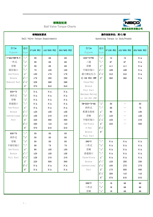
球阀扭矩表Ball Valve Torque Charts美国尼伯科有限公司球阀扭矩要求Ball Valve Torque Requirements操作扭矩单位:英寸/磅Operating Torque in Inch/Pounds型号# Figure#通径Size0-100 PSI 101-500 PSI 501-600 PSIT-560-BR-R/Y 一件式青铜缩径端口One-PieceBronze Reduced Port 1/4"3/8"1/2"3/4"1"11/4"11/2"2"35353570130175225370656565100175230265510656565100175230265510580-70两件式青铜普通端口Two-PieceBronze ConventionalPort 1/4"3/8"1/2"3/4"1"11/4"11/2"2"21/2"3"N/AN/AN/AN/AN/A120185220250370N/AN/AN/AN/AN/A185240300410540N/AN/AN/AN/AN/A185240300410540585-70 两件式青铜不缩径端口Two-Piece Bronze Full Port 1/4"3/8"1/2"3/4"1"11/4"11/2"2"21/2"3"3030305590120185220N/AN/A50505075130185240300N/AN/A50505075130185240300N/AN/A型号#Figure#通径Size0-100 PSI 101-500 PSI 501-600 PSI585-70-W3三通青铜不缩径端口最大额定压力是400 PSI CWPThree-WayBronzeFull PortMaximum Ratingis 400 PSI CWP1/2"3/4"1"11/4"11/2"2"42671141592182684267114159218268N/AN/AN/AN/AN/AN/ATM-585-70-66两件式配置安装座青铜不缩径端口Two-Piecew/PadBronzeFull Port1/2"3/4"1"11/4"11/2"2"21/2"3"305590120185220——————3075130185240300590-Y三件式青铜普通端口Three-PieceBronzeConventionalPort1/4"3/8"1/2"3/4"1"11/4"11/2"2"21/2"3"N/AN/AN/AN/AN/A125150170250370N/AN/AN/AN/AN/A230275300410540N/AN/AN/AN/AN/A230275300410540595-Y三件式青铜1/4"3/8"1/2"454545656565656565不缩径端口Three-Piece Bronze Full Port3/4"1"11/4"11/2"2"21/2"3"50125150170250370N/A80230275300410540N/A80230275300410540N/A型号# Figure#通径Size0-100 PSI 101-500 PSI 501-600 PSI 601-1000 PSI 1001-1500 PSI 1501-2000 PSIT-560-CS/S6-R 一件式碳钢/不锈钢缩径端口One-PieceCS/SS Reduced Port1/4"3/8"1/2"3/4"1"11/4"11/2"2"40404075135180225370707070100190240300460757580105200250310490808085110215270330580858590125245290365685100100110140275330410790T-570-CS-R一件式棒材碳钢缩径端口One-Piece Bar StockCS Reduced Port1/2"3/4"1"11/4"11/2"2"40701251702103506595180230285440701001902402954708010520526032056090120240285355665105135270320395770T-580-CS-R两件式碳钢普通端口Two-PieceCS ConventionalPort1/4"3/8"1/2"3/4"1"11/4"11/2"240407510012016520029040407510013017520030050508511014018522032055559512015020025035065651051301702503004008080125150215300350450 球阀扭矩表(2)Ball Valve Torque Charts (2)美国尼伯科有限公司球阀扭矩要求Ball Valve Torque Requirements操作扭矩单位:英寸/磅Operating Torque in Inch/Pounds浮动球阀的操作扭矩软密封浮动式球阀的操作扭矩是基于常温、清洁介质计算的。
PISCO流量开关说明书

进入菜单程序时, 依次进入如下界面 : 最高流速校正模式 最低流速校正模式
开关点设定模式 回差值设定模式
锁定模式 进入设置后出现S U表 示 正 常; 出 现Er表 示 错 误, 出
------ ------ ------ ------ ------ ------
------ ------ ------ ------ ------ ------
-12-
不锈钢外壳
测量水 测量油
测量气体 G 1 /4外螺 纹 G 1 /2外螺 纹 NPT 1/2外螺纹
常 用 型 号: FS1-LG101508P-F 有 些 型 号 需 要 定 制,定 制 的 供 货 时 间 比 一 般 型 号 要 长4周 。
热式流量开关
Pisco公 司
德 国Pisco公 司 热 式 流 量 开 关
热式流量开关的热导示流器是基于热交换原理设计, 探头内置发热模块以及感热模块, 示流器的热 量传导与被测流体流速密切相关,如果管道内没有介质流动,感热模块接收到的热量是一个固定值 ,而 当流体介质流过示流器探头时 ,感热模块所接收到的热量随介质的流速变化而变化,感热模块再将这温 差 信 号 转 化 成 电 信 号,处 理 器 再 将 其 转 换 成4~20mA电 信 号 或 与 设 定 流 量 对 应 的 接 点 信 号 输 出。
为了便于查看显示请转动仪表位置以使显示正对自己垂直安装时气体应该从下向上水平安装时应该侧装避免非满管和污物连接电缆m12x1标准配置带2m电缆pnpnpn热式流量开关德国pisco热式流量开关的热导示流器是基于热交换原理设计探头内置发热模块以及感热模块示流器的热量传导与被测流体流速密切相关如果管道内没有介质流动感热模块接收到的热量是一个固定值而当流体介质流过示流器探头时感热模块所接收到的热量随介质的流速变化而变化感热模块再将这温差信号转化成电信号处理器再将其转换成420ma电信号或与设定流量对应的接点信号输出
采油树材料级别的选择

410SS
410SS Hard surfacd 410SS Hard surfacd
410SS
AISI4130
AISI4135 Hard
surfaced
AISI4130 Hard
surfaced
AISI4130
AISI4130
410SS Hard surfaced
410SS Hard surfaced
延伸率
(δ4标距2寸,%min)
断面收缩率
(ψ,%min)
36K
36000
70000
21
没有要求
45K
45000
70000
19
32
60K
60000
85000
18
35
75K
75000
95000
18
35
江苏金石机械集团
No Image
产品设计
井口和采油树总成主要零件明细
No Image
பைடு நூலகம்
江苏金石机械集团
insert
AISI4130
PH17-4 Head is hard alloy
410SS Hard alloy
insert
FF
410SS
410SS Hard surfaced 410SS Hard surfaced
410SS
PH17-4
410SS
PH17-4 Head is hard alloy
410SS Hard alloy
江苏金石机械集团
No Image
江苏金石机械集团
No Image
产品设计
本体盖端部和出口连接的标准材料应用
API_602紧凑型闸阀特点

API 602紧凑型闸阀特点API 602 Compact Gate Features(1) 明杆 - 易于观察开启-关闭状态。
(1) Rising Stem – easily visibleopen-close indication. (2) 润滑油附件 - 轭架套管配置润滑油附件,降低磨损和操作扭矩。
(2) Grease Fittings – yokesleeves equipped with grease fittings tominimize wear and operatingtorque.(3) 旋启式螺栓 - 使得维护和填料更换更加简便易行。
(3) Swing Bolts – facilitate easiermaintenance and packingreplacement.(4) 填料函 - 可配置备选灯笼环和润滑油注射器。
(4) Stuffing Box – optional lantern rings and grease injectors areavailable.(5) 阀盖连接 - 封装垫圈结构。
(5) Bonnet Joint – encapsulatedgasket design.(6) 阀体 - 全流道(全端口),重型阀体,符合API 602标准的壁厚,最大限度延长使用寿命。
(6) Body – full ported, heavy duty body with API 602 wall thickness for maximum service life. (7) 阀座环 - 分离式重型、全流道(全端口)环,易于维护。
(7) Seat Rings – separate heavy duty, full ported rings for easymaintenance.(8) 手轮 - 易于操作的大手轮。
(8) Handwheel – largehandwheels for easy operation.(9) 轭架套管 - 配置416不锈钢或铝青铜材料。
布利摩盒式阀门B211技术数据册说明书

B211•ApplicationStainless Steel Ball and StemTechnical dataFunctional dataValve Size 0.5" [15]Fluidchilled or hot water, up to 60% glycol Fluid Temp Range (water)0...250°F [-18...120°C]Body Pressure Rating 600 psi Close-off pressure ∆ps 200 psiFlow characteristic equal percentage Servicing maintenance-free Flow Pattern 2-way Leakage rate0% for A – AB Controllable flow range 75°Cv1.9 Body pressure rating note 600 psiCv Flow RatingA-port: as stated in chart B-port: 70% of A – AB Cv MaterialsValve body Nickel-plated brass body Stem seal EPDM (lubricated)SeatPTFEPipe connection NPT female ends O-ring EPDM (lubricated)Ballstainless steel Suitable actuatorsNon-SpringTR LRB(X)NRSafety notesWARNING: This product can expose you to lead which is known to the State of California to cause cancer and reproductive harm. For more information go to Product featuresThis valve is typically used in air handling units on heating or cooling coils, and fan coil unit heating or cooling coils. Some other common applications include Unit Ventilators, VAV box re-heat coils and bypass loops. This valve is suitable for use in a hydronic system with variable flow.Flow/Mounting detailsB211 DimensionsDimensional drawingsLRB, LRXA B C D E F H1H29.4" [239] 2.4" [60] 5.2" [132] 4.6" [117] 1.3" [33] 1.3" [33] 1.2" [30] 1.1" [28]TRA B C D E F3.7" [95] 2.4" [60]4.8" [122] 4.2" [107] 1.3" [33] 1.3" [33]TFRB, TFRXA B C D E F6.6" [167] 2.4" [60] 4.9" [124] 4.3" [110] 1.5" [39] 1.5" [39]LFA B C D E F7.9" [200] 2.4" [60] 5.7" [146] 5.1" [129] 1.8" [46] 1.8" [46]ARB N4, ARX N4, NRB N4, NRX N4A B C D E F11.4" [289] 2.4" [60]7.7" [196]7.0" [179] 3.1" [80] 3.1" [80]B211TFRB, TFRXA B C D E F6.6" [167] 2.4" [60] 4.9" [124] 4.3" [110] 1.5" [39] 1.5" [39]ARB N4, ARX N4, NRB N4, NRX N4A B C D E F11.4" [289] 2.4" [60]7.7" [196]7.0" [179] 3.1" [80] 3.1" [80]TR24-SR US••••••Modulating, Non-Spring Return, 24 V, for DC 2...10 V or 4...20 mATechnical dataElectrical dataNominal voltageAC/DC 24 V Nominal voltage frequency 50/60 Hz Power consumption in operation 0.5 WTransformer sizing 1 VA (class 2 power source)Electrical Connection 18 GA plenum cable, 3 ft [1 m]Overload Protectionelectronic throughout full rotation Functional dataOperating range Y 2...10 VOperating range Y note 4...20 mA w/ ZG-R01 (500 Ω, 1/4 W resistor)Input Impedance 100 kΩ for 2...10 V (0.1 mA), 500 Ω for 4...20 mA Direction of motion motor selectable with switch Manual override push down handle Angle of rotation 90°Running Time (Motor)90 s / 90°Noise level, motor 35 dB(A)Position indicationMechanically, pluggable Safety dataDegree of protection IEC/EN IP40Degree of protection NEMA/UL NEMA 1 UL Enclosure Type 1Agency ListingcULus acc. to UL60730-1A/-2-14, CAN/CSAE60730-1:02, CE acc. to 2014/30/EU and 2014/35/EU; Listed to UL 2043 - suitable for use in air plenums per Section 300.22(c) of the NEC and Section 602.2 of the IMC Quality Standard ISO 9001Ambient temperature -22...122°F [-30...50°C]Storage temperature -40...176°F [-40...80°C]Ambient humidity max. 95% r.H., non-condensing Servicingmaintenance-free WeightWeight0.70 lb [0.32 kg]Safety notesCable for ZIP-RS232 US and ZIP-USB-MP US to Belimo gateways.Battery Back Up System for SY(7~10)-110120 to 24 VAC, 40 VA transformer.Cable for ZTH US to actuators w/o diagnostics socket.50% voltage divider kit (resistors with wires).PC Tool computer programming interface, serial port.Electrical installationTR24-SR USINSTALLATION NOTESProvide overload protection and disconnect as required.Actuators may also be powered by 24 VDC.Only connect common to negative (-) leg of control circuits.A 500 Ω resistor (ZG-R01) converts the 4...20 mA control signal to 2...10 V.Actuators may be connected in parallel if not mechanically linked. Power consumption and inputimpedance must be observed.Meets cULus requirements without the need of an electrical ground connection.Warning! Live Electrical Components!During installation, testing, servicing and troubleshooting of this product, it may be necessary to workwith live electrical components. Have a qualified licensed electrician or other individual who has beenproperly trained in handling live electrical components perform these tasks. Failure to follow all electricalsafety precautions when exposed to live electrical components could result in death or serious injury.2...10 V / 4...20 mA Control。
parker节流阀工作原理
parker节流阀工作原理Parker节流阀工作原理节流阀是一种常见的液压控制元件,用于控制液压系统中流体的流量和压力。
其中,Parker节流阀是一种高精度的节流阀,具有稳定可靠的性能。
本文将介绍Parker节流阀的工作原理及其应用。
一、Parker节流阀的工作原理Parker节流阀是通过调节流体通过节流孔的面积来控制流量和压力的。
其工作原理如下:1. 压力控制阀:Parker节流阀通过调节阀芯的位置来改变节流孔的开口面积,从而控制流体通过节流孔的流量。
当阀芯向下移动时,节流孔的开口面积变小,流量减小;当阀芯向上移动时,节流孔的开口面积变大,流量增加。
通过不断调节阀芯的位置,可以实现精确的流量控制。
2. 压力控制阀:Parker节流阀还可以通过调节阀芯的位置来改变节流孔前后的压力差,从而控制流体通过节流孔的压力。
当阀芯向下移动时,节流孔前后的压力差增大,流体的压力也增大;当阀芯向上移动时,节流孔前后的压力差减小,流体的压力也减小。
通过不断调节阀芯的位置,可以实现精确的压力控制。
二、Parker节流阀的应用Parker节流阀广泛应用于各种液压系统中,常见的应用场景包括:1. 流量控制:Parker节流阀可以用于控制液压系统中的流量,通过调节节流孔的开口面积,实现对流体流量的精确控制。
这在需要控制流体速度或节流流体的工艺过程中非常重要,如液压缸的缓冲控制、液压马达的速度控制等。
2. 压力控制:Parker节流阀可以用于控制液压系统中的压力,通过调节节流孔前后的压力差,实现对流体压力的精确控制。
这在需要控制液压系统的工作压力或保护系统的安全压力时非常重要,如液压系统的过载保护、液压系统的稳压控制等。
3. 温度控制:Parker节流阀还可以用于控制液压系统中的温度,通过调节节流孔的开口面积,实现对流体流量的控制,进而控制流体的温度。
这在需要控制液压系统的工作温度或防止系统过热时非常重要,如液压系统的温度控制、液压系统的冷却控制等。
- 1、下载文档前请自行甄别文档内容的完整性,平台不提供额外的编辑、内容补充、找答案等附加服务。
- 2、"仅部分预览"的文档,不可在线预览部分如存在完整性等问题,可反馈申请退款(可完整预览的文档不适用该条件!)。
- 3、如文档侵犯您的权益,请联系客服反馈,我们会尽快为您处理(人工客服工作时间:9:00-18:30)。
Pisco节流阀使阀瓣的轴线严格的垂直于水平面,以保证阀瓣的灵活升降与可靠工作。
旋启式止回阀只要保证阀瓣的旋转枢轴呈水平,就可任意安装在水平、垂直或倾斜管路上。
8.1.2逆止阀主要性能参数8.1.2.1再热器右侧进口管道逆止阀,规格:PN4.65DN850。
8.2逆止阀检修步骤、工艺方法及质量标准8.2.1逆止阀检修准备8.2.1.1准备工作8.2.1.1.1确证在阀门内腔和与之相连接的管道内工作,介质没有压力。
8.2.1.1.2准备好拆卸阀门的场所,防止堆放时损坏零件。
8.2.1.1.3准备好必要的测绘用器具。
8.2.2逆止阀检修步骤、工艺方法8.2.2.1阀门解体8.2.2.1.1松开盖板螺母,取下盖板。
一、产品[低温截止(节流)阀]的详细资料:产品名称:低温截止(节流)阀产品特点:国标低温截止阀,国标低温节流阀,低温截止阀二、执行标准:设计与制造结构长度浩兰尺寸压力-温度试验-检验JB/T7749 GB12221 JB79 GB9131 JB/T9092三、压力试验:公称压力PN 1.6 2.5 4.0强度试验 2.4 3.8 6.0水密封试验 1.8 2.8 4.4上密封试验 1.8 2.8 4.4气密封试验0.4-0.7四、主要零件材料及性能:体盖板阀杆密封面垫片埴料工作温度℃适用介质LCB1Cr17Ni12DTL/DTL 1Cr13/柔性石墨低温石棉PTFE浸四氟乙烯石棉绳柔性石墨-46丙烷/丙烯甲醇,乙烷煤气/液氨LC1 -60 LC2 -73LC31Cr18Ni9Ti -101LC4 -115 LC8 -196 五、国标低温截止阀(节流)阀PNl.6MPa一4.0MPa 规格主要尺寸:1.6MPa DNL D D1 D2 b n-ΦdHD0-46℃4-101℃-196℃凸面法兰RFDJ41Y-16L DJ41Y-16L C1 DJ41Y-16L C2 DJ41Y-16L C3 DJ41Y-16L C4 DJ41Y-16P DJ41Y-16R 5023160 125 100 16 4-Φ18460 480 520 240 6529180 145 120 18 4-Φ18475 505 525 280 8031195 160 135 20 8-Φ18520 550 590 280 1035215 180 155 20 8-Φ18545 575 615 320 12540245 210 185 22 8-Φ18590 620 660 360 1548280 240 210 24 8-Φ23650 680 730 400 2060335 295 265 26 12-Φ23850 880 930 400 2573405 355 320 30 12-Φ25956 986 1036 450 3085460 410 375 30 12-Φ251095 1125 1175 5002.5MPa 50 23160 125 100 20 4-Φ18460 460 520 240凸面法兰RFDJ41Y-25L 6529180 145 120 22 8-Φ18475 505 525 280 80 31195 160 135 22 8-Φ18520 550 590 280DJ41Y-25L C1 DJ41Y-25L C2 DJ41Y-25L C3 DJ41Y-25L C4 DJ41Y-25P DJ41Y-25R1035230 190 160 24 8-Φ23545 575 615 320 12540270 220 188 28 8-Φ25590 620 660 360 1548300 250 218 30 8-Φ25650 680 730 400 2060360 310 278 34 12-Φ25850 880 930 400 2573425 370 332 36 12-Φ30956 986 1036 450 3085485 430 390 40 16-Φ301095 1125 1175 5004.0MPa 50 23160 125 100 20 4-Φ18483 504 546 240凸面法兰RFDJ41Y-40L DJ41Y-40L C1 DJ41Y-40L C2 DJ41Y-40L C3 DJ41Y-40L C4 DJ41Y-40P DJ41Y-40R 6529180 145 120 22 8-Φ18499 530 551 280 8031195 160 135 22 8-Φ18546 578 620 280 1035230 190 160 24 8-Φ23572 604 646 320 12540270 220 188 28 8-Φ25620 651 693 360 1548330 2850 218 30 8-Φ25683 741 767 400 2060375 320 282 38 12-Φ30893 924 977 400 2573445 385 345 42 12-Φ341004 1035 1088 450 3085510 450 408 46 16-Φ341150 1181 1234 500一、产品[水封式阀门]的详细资料:产品名称:水封式阀门产品特点:工洲牌DS系列水封阀门适用于公称压力≤4 DMPa,工作温度≤400℃或≤550℃,工作介质为水蒸汽油品和非腐蚀性气体的管路上作启闭装置用.尤其适用于火电厂汽机真空冷凝系统有截止阀和闸阀两种形式.水封式阀门价格,水封式阀门厂家,水封式阀门报价。
二、结构与性能特点:1结构形式:阀盖填料室具有水循环密封结构,当接口通人压力为0 6~l 0MPa的水时.可使系统与大气隔离,保证系统具有良好的气密性.2连接形式:承插焊连接.法兰连接和焊接连接.3驱动方式:手动和电动.4 DS/Z型系列采用双闸板双向弹性密封、启闭灵活迅速密封可靠;真空隔断截止阀阀杆与阁瓣采用动连接,阀瓣与阀座垂直座封;启闭行程和阀门高度小.5产品结构简单紧凑合理检修方便使用寿命长.6在管路上作启闭置用.必须处于全开或全闭状态,不得用于调节流量.三、主要性能规范-试验压力:试验压力公称压力PN(MPa)1.0 1.62.5 4.0 6.4 10.0壳体强度试验 1.5 2.4 3.8 6.0 9.6 15.0密封试验 1.1 1.8 2.8 4.4 7.0 11.0上密封试验 1.1 11.8 2.8 4.4 7.0 11.0四、使用范围:产品类别适用温度() 适用介质碳钢型(C) ≤400水、蒸汽、油品、非腐蚀性气体合金钢(I) ≤550五、主要零件材料:产品类型零件名称阀体、阀盖、支架阀杆阀扳、阀瓣、密封面阀座密封面阀杆螺母填料碳钢型(C) WCB252Cr13Cr13型不锈钢或硬质合金Crl3型小锈钢铝青铜柔性石墨合金钢(I) WC6WC925Cr2Mo1V A硬质合盒硬质合金一、产品[直流式对焊截止阀]的详细资料:产品名称:直流式对焊截止阀产品特点:高温高压直流式对焊截止阀,直流式对焊截止阀,高温高压截止阀二、主要零件材料:零件名称材料牌号阀体WCB WC6 WC9 活塞A105 WC6 WC9 阀盖25 12Cr1MoV A阀杆1Cr17Ni2 20Cr1Mo1V1A密封环05F 05F 柔性石墨四开环1Cr13 20CrMOIVIA填料BSP-600 BSP-600支架WCB WCB阀杆螺母ZQAL9-4 ZQAL9-4三、应用规范:1、设计制造JB3595规定2、结构长度按JB3595规定或按用户要求3、连接端按JB3595规定或按用户要求4、阀门检查和试验按JB3595规定四、订货号、尺寸和重量:公称通径DN(mm)尺寸(mm)重量(Kg)L D1 Do H Lo L1PN32(320)J565Y-320V型80 390 64 120 750 - - 121 100 480 108 185 870 - - 212 125 533 132 218 995 - - 312 150 610 166 245 1205 - - 510 175 750 175 278 1565 - - 708 200 762 200 290 1670 - - 980 225 850 108 310 1705 - - 1060 250 914 248 348 1870 - - 1380 300 1041 300 430 2335 - - 2824 P54(140)J565Y-P54140V型80 390 64 120 750 - - 130100 480 108 185 870 - - 212125 580 132 218 995 - - 312150 630 166 245 1205 - - 510175 750 175 278 1565 - - 708200 771 200 290 1670 - - 980225 850 108 310 1705 - - 1060250 930 248 348 1870 - - 1380300 1060 300 430 2335 - - 2824说明:凡按用户要求的须在合同中写明。
一、产品[氧气管路专用截止阀]的详细资料:产品名称:氧气管路专用截止阀产品特点:氧气管路专用截止阀,氧气专用截止阀,截止阀。
二、压力试验:公称压力强度试验水密封试验上密封试验气密封试验2.53.8 2.8 2.8 0.64.0 6.0 4.4 4.4三、主要零件材料及性能:体盖阀杆阀瓣密封面垫片填料工作温度适用介质1Cr18Ni9Ti1Cr18Ni9Ti 1Cr18Ni9Ti本体材质PTFE PTFE 常温氧气ZCrZn16Si4四、工洲牌氧气管路专用截止阀规格主要尺寸:1.6MPa DN L D D1 D2 b n-Φd H Do凸面法兰25 160 115 85 65 14 4-Φ14305 160 32 180 135 100 78 16 4-Φ18316 160RF JY41W-16P JY41W-16T JY41Y-16P JY41Y-16T 40 200 145 110 85 16 4-Φ18328 180 50 230 160 125 100 16 4-Φ18356 200 65 290 180 145 125 18 4-Φ18389 280 80 310 195 160 135 20 8-Φ18400 280 100 350 215 180 155 20 8-Φ18460 320 125 400 245 210 185 22 8-Φ18528 320 150 480 280 240 210 24 8-Φ23668 450 200 600 335 295 265 26 26-Φ23795 500 250 650 405 355 320 30 30-Φ25910 560 300 750 460 410 375 30 30-Φ251200 640 350 850 520 470 435 34 34-Φ251200 720 400 950 580 525 485 36 36-Φ301560 800五、PN2.5MPa-4.0MPa氧气管路专用截止阀:六、工洲牌氧气管路专用截止阀规格主要尺寸:2.5MPa DN L D D1 D2 b n-Φd H DO 25 160 115 85 65 16 4-Φ14305 160凸面法兰RF JY41W-25P JY41W-16T HY41Y-16P JY41Y-16T 32 180 135 100 78 18 4-Φ18316 160 40 200 145 110 85 18 4-Φ18 328 180 50 230 160 125 100 20 4-Φ18356 200 65 290 180 145 120 22 8-Φ18389 280 80 310 195 160 135 22 8-Φ18400 280 100 350 230 190 160 24 8-Φ23460 320 125 400 270 220 188 28 8-Φ25538 320 150 480 300 250 218 30 8-Φ25668 450 200 600 360 310 278 34 12-Φ25795 500 250 650 425 370 332 36 12-Φ30910 560 300 750 485 430 390 40 16-Φ301200 640 350 850 550 490 448 44 16-Φ341290 720 400 950 610 550 505 48 16-Φ341560 8004.0MPa 25 160 115 85 65 16 4-Φ14305 160凸面法兰RF JY41W-40P JY41W-40T HY41Y-40P JY41Y-40T 32 180 135 100 78 18 4-Φ18316 160 40 200 145 110 85 18 4-Φ18328 180 50 230 160 125 100 20 4-Φ18356 200 65 290 180 145 120 22 8-Φ18389 280 80 310 195 160 135 22 8-Φ18400 280 100 350 230 190 160 24 8-Φ23460 320 125 400 270 220 188 28 8-Φ25538 320 150 480 300 250 218 30 8-Φ25668 450 200 600 375 320 282 38 12-Φ30795 500 250 650 445 385 345 42 12-Φ34910 560 300 750 510 450 408 46 16-Φ341200 640 350 850 570 510 465 52 16-Φ341290 720 400 950 655 585 535 58 16-Φ411560800一、产品说明:美标截止阀特点:①产品的设计制造符合美国国家标准ANS1B16.34,美国BS1873等国外先进标准要求。
