供配电相关外文翻译(内附原文PDF格式下载地址)
电气供配电系统大学毕业论文英文文献翻译及原文

毕业设计(论文)外文文献翻译文献、资料中文题目:供配电系统文献、资料英文题目:POWER SUPPLY AND DISTRIBUTIONSYSTEM文献、资料来源:文献、资料发表(出版)日期:院(部):专业:班级:姓名:学号:指导教师:翻译日期: 2017.02.14POWER SUPPLY AND DISTRIBUTION SYSTEMABSTRACTThe basic function of the electric power system is to transport the electric power towards customers. The l0kV electric distribution net is a key point that connects the power supply with the electricity using on the industry, business and daily-life. For the electric power, allcostumers expect to pay the lowest price for the highest reliability, but don't consider that it's self-contradictory in the co-existence of economy and reliable.To improve the reliability of the power supply network, we must increase the investment cost of the network construction But, if the cost that improve the reliability of the network construction, but the investment on this kind of construction would be worthless if the reducing loss is on the power-off is less than the increasing investment on improving the reliability .Thus we find out a balance point to make the most economic,between the investment and the loss by calculating the investment on power net and the loss brought from power-off.KEYWARDS:power supply and distribution,power distribution reliability,reactive compensation,load distributionTEXTThe revolution of electric power system has brought a new big round construction,which is pushing the greater revolution of electric power technique along with the application of new technique and advanced equipment. Especially, the combination of the information technique and electric power technique, to great ex- tent, has improved reliability on electric quality and electric supply. The technical development decreases the cost on electric construction and drives innovation of electric network. On the basis of national and internatio- nal advanced electric knowledge, the dissertation introduces the research hotspot for present electric power sy- etem as following.Firstly, This dissertation introduces the building condition of distribution automation(DA), and brings forward two typical construction modes on DA construction, integrative mode and fission mode .It emphasize the DA structure under the condition of the fission mode and presents the system configuration, the main station scheme, the feeder scheme, the optimized communication scheme etc., which is for DA research reference.Secondly, as for the (DA) trouble measurement, position, isolation and resume, This dissertation analyzes the changes of pressure and current for line problem, gets math equation by educing phase short circuit and problem position under the condition of single-phase and works out equation and several parameter s U& , s I& and e I& table on problem . It brings out optimized isolation and resume plan, realizes auto isolation and network reconstruction, reduces the power off range and time and improves the reliability of electric power supply through problem self- diagnoses and self-analysis. It also introduces software flow and use for problem judgement and sets a model on network reconstruction and computer flow.Thirdly, electricity system state is estimated to be one of the key techniques in DA realization. The dissertation recommends the resolvent of bad measurement data and structure mistake on the ground of describing state estimate way. It also advances a practical test and judging way on topology mistake in state estimate about bad data test and abnormity in state estimate as well as the problem and effect on bad data from state measure to state estimate .As for real time monitor and control problem, the dissertation introduces a new way to solve them by electricity break and exceptional analysis, and theway has been tested in Weifang DA.Fourthly, about the difficulty for building the model of load forecasting, big parameter scatter limit and something concerned, the dissertation introduces some parameters, eg. weather factor, date type and social environment effect based on analysis of routine load forecasting and means. It presents the way for electricity load forecasting founded on neural network(ANN),which has been tested it’s validity by example and made to be good practical effect.Fifthly, concerning the lack of concordant wave on preve nting concordant wave and non-power compensation and non-continuity on compensation, there is a topology structure of PWM main circuit and nonpower theory on active filter the waves technique and builds flat proof on the ground of Saber Designer and proves to be practical. Meanwhile, it analyzes and designs the way of non-power need of electric network tre- nds and decreasing line loss combined with DA, which have been tested its objective economic benefit throu- gh counting example.Sixthly, not only do the dissertation design a way founded on the magrginal electric price fitted to our present national electric power market with regards to future trends of electric power market in China and fair trade under the government surveillance, that is group competitio n in short-term trade under the way of grouped price and quantity harmony, but also puts forward combination arithmetic, math model of trading plan and safty economical restriction. It can solve the original contradiction between medium and long term contract price and short term competitive price with improvement on competitive percentage and cut down the unfair income difference of electric factory, at the same time, it can optimize the electric limit for all electric factories and reduce the total purchase charge of electric power from burthen curve of whole electric market network.The distribution network is an important link among the power system. Its neutral grounding mode and operation connects security and stability of the power system directly. At the same time, the problem about neutral grounding is associated with national conditions, natural environment, device fabrication and operation. For example, the activity situation of the thunder and lightning, insulating structure and the peripheral interference will influence the choice of neutral grounding mode Conversely, neutral grounding mode affects design, operation, debugs and developing. Generally in the system higher in grade in the voltage, the insulating expenses account for more sizable proportion at the total price of the equipment. It is very remarkable to bring the economic benefits by reducing the insulating level. Usually such system adopt the neutral directly grounding andadopt the autoreclosing to guarantee power supply reliability. On the contrary, the system which is lower in the voltage adopts neutral none grounding to raise power supply reliability. So it is an important subject to make use of new- type earth device to apply to the distribution network under considering the situation in such factors of various fields as power supply reliability, safety factor, over-voltage factor, the choice of relay protection, investment cost, etc.The main work of this paper is to research and choice the neutral grounding mode of the l0kV distribution network. The neutral grounding mode of the l0kV network mainly adopts none grounding, grounding by arc suppressing coil, grounding by reactance grounding and directly grounding. The best grounding mode is confirmed through the technology comparison. It can help the network run in safety and limit the earth electric arc by using auto-tracking compensate device and using the line protection with the detection of the sensitive small ground current. The paper introduces and analyzes the characteristic of all kind of grounding modes about l0kV network at first. With the comparison with technological and economy, the conclusion is drawn that the improved arc suppressing coil grounding mode shows a very big development potential.Then, this paper researches and introduces some operation characteristics of the arc suppressing coil grounding mode of the l0kV distribution network. And then the paper put emphasis on how to extinguish the earth electric arc effectively by utilizing the resonance principle. This paper combines the development of domestic and international technology and innovative achievement, and introduces the computer earth protection and autotracking compensate device. It proves that the improved arc suppressing coil grounding mode have better operation characteristics in power supply reliability, personal security, security of equipment and interference of communication. The application of the arc suppressing coil grounding mode is also researched in this paper.Finally, the paper summarizes this topic research. As a result of the domination of the arc suppressing coil grounding mode, it should be more popularized and applied in the distribution network in the future.The way of thinking, project and conclusions in this thesis have effect on the research to choose the neutral grounding mode not only in I0kV distribution network but also in other power system..The basic function of the electric power system is to transport the electric power towards customers. The l0kV electric distribution net is a key point that connects the power supply with the electricity using on the industry, business and daily-life. For the electric power, all costumers expect to pay the lowest price for the highest reliability, butdon't consider that it's self-contradictory in the co-existence of economy and reliable. To improve the reliability of the power supply network, we must increase the investment cost of the network con- struction But, if the cost that improve the reliability of the network construction, but the investment on this kind of construction would be worthless if the reducing loss is on the power-off is less than the increasing investment on improving the reliability .Thus we find out a balance point to make the most economic, between the investment and the loss by calculating the investment on power net and the loss brought from power-off. The thesis analyses on the economic and the reliable of the various line modes, according to the characteristics various line modes existed in the electric distribution net in foshan..First, the thesis introduces as the different line modes in the l0kV electric distribution net and in some foreign countries. Making it clear tow to conduct analyzing on the line mode of the electric distribution net, and telling us how important and necessary that analyses are.Second, it turns to the necessity of calculating the number of optimization subsection, elaborating how it influences on the economy and reliability. Then by building up the calculation mode of the number of optimization subsection it introduces different power supply projects on the different line modes in brief. Third, it carries on the calculation and analyses towards the reliability and economy of the different line modes of electric distribution net, describing drafts according by the calculation. Then it makes analysis and discussion on the number of optimization subsection.At last, the article make conclusion on the economy and reliability of different line modes, as well as, its application situation. Accordion to the actual circumstance, the thesis puts forward the beneficial suggestion on the programming and construction of the l0kV electric distribution net in all areas in foshan. Providing the basic theories and beneficial guideline for the programming design of the lOkV electric distribution net and building up a solid net, reasonable layout, qualified safe and efficiently-worked electric distribution net.。
电气外文文献 翻译
Circuit breaker断路器Compressed air circuit breaker is a mechanical switch equipment, can be i 空气压缩断路器是一种机械开关设备,能够在n normal and special conditions breaking current (such as short circuit cur 正常和特殊情况下开断电流(比如说短路电流)。
rent). For example, air circuit breaker, oil circuit breaker, interference circ 例如空气断路器、油断路器,干扰电路的导体uit conductor for the application of the safety and reliability of the circuit 干扰电路的导体因该安全可靠的应用于其中,breaker, current in arc from is usually divided into the following grades: a 电流断路器按灭弧远离通常被分为如下等级:ir switch circuit breaker, oil circuit breaker, less oil circuit breaker, compr 空气开关断路器、油断路器、少油断路器、压缩空essed air circuit breaker, a degaussing of isolating switch, six sulfur hexaf 气断路器、具有消磁性质的隔离开关、六氟luoride circuit breaker and vacuum breaker. Their parameters of voltage, 化硫断路器和真空断路器。
他们的参数有电压等级、current, insulation level of breaking capacity, instantaneous voltage off ti 开断容量的电流、绝缘等级开断时间的瞬时电压恢复和me of recovery and a bombing. Breaker plate usually include: 1 the maxi 轰炸时间。
电力系统继电保护技术中英文对照外文翻译文献

中英文对照外文翻译文献(文档含英文原文和中文翻译)原文:Relay protection development present situationAbstract: Reviewed our country electrical power system relay protection technological development process, has outlined the microcomputer relay protection technology achievement, propose the future relay protection technological development tendency will be: Computerizes, networked, protects, the control, the survey, the data communication integration and the artificial intellectualization.Key word: relay protection, present situation development, future development1 relay protection development present situation- 1 -The electrical power system rapid development to the relay protection propose unceasingly the new request, the electronic technology, computer technology and the communication rapid development unceasingly has poured into the new vigor for the relay protection technology development, therefore, the relay protection technology is advantageous, has completed the development 4 historical stage in more than 40 years time.After the founding of the nation, our country relay protection discipline, the relay protection design, the relay manufacture industry and the relay protection technical team grows out of nothing, has passed through the path in about 10 years which advanced countries half century passes through. The 50's, our country engineers and technicians creatively absorption, the digestion, have grasped the overseas advanced relay protection equipment performance and the movement technology , completed to have the deep relay protection theory attainments and the rich movement experience relay protection technical team, and grew the instruction function to the national relay protection technical team's establishment. The relay factory introduction has digested at that time the overseas advanced relay manufacture technology, has established our country relay manufacturing industry. Thus our country has completed the relay protection research, the design, the manufacture, the movement and the teaching complete system in the 60's. This is a time which the mechanical and electrical relay protection prospers, was our countries relay protection technology development has laid the solid foundation.From the end of the 50's, the transistor relay protection was starting to study. In the 60's to the 80's,it is the times which the transistor relay protection vigorous development and widely used. Tianjin University and the Nanjing electric power automation plant cooperation research 500kV transistor direction high frequency protection the transistor high frequency block system which develops with the Nanjing electric power automation research institute is away from the protection, moves on the Gezhou Dam 500kV line , finished the 500kV line protection to depend upon completely from the overseas import time.- 2 -From the 70's, start based on the integration operational amplifier integrated circuit protection to study. Has formed the completely series to at the end of 80's integrated circuit protection, substitutes for the transistor protection gradually. The development, the production, the application the integrated circuit protects which to the beginning of the 90's still were in the dominant position, this was the integrated circuit protection time. The integrated electricity road work frequency conversion quantity direction develops which in this aspect Nanjing electric power automation research institute high frequency protected the vital role, the Tianjin University and the Nanjing electric power automation plant cooperation development integrated circuit phase voltage compensated the type direction high frequency protection also moves in multi- strip 220kV and on the 500kV line.Our country namely started the computer relay protection research from the end of the 70's, the institutions of higher learning and the scientific research courtyard institute forerunner's function. Huazhong University of Science and Technology, southeast the university, the North China electric power institute, the Xian Jiao tong University, the Tianjin University, Shanghai Jiao tong University, the Chongqing University and the Nanjing electric power automation research institute one after another has all developed the different principle, the different pattern microcomputer protective device. In 1984 the original North China electric power institute developed the transmission line microcomputer protective device first through the evaluation and in the system the find application, had opened in our country relay protection history the new page, protect the promotion for the microcomputer to pave the way. In the host equipment protection aspect, the generator which southeast the university and Huazhong University of Science and Technology develop loses magnetism protection, the generator protection and the generator? Bank of transformers protection also one after another in 1989、1994 through appraisal and investment movement. The Nanjing electric power automation research institute develops microcomputer line protective device also in 1991 through appraisal. The Tianjin University and the Nanjing electric power automation plant cooperation development- 3 -microcomputer phase voltage compensated the type direction high frequency protection, the Xian Jiao tong University and the Xuchang Relay Factory cooperation development positive sequence breakdown component direction high frequency protection also one after another in 1993, in 1996 through the appraisal. Here, the different principle, the different type microcomputer line and the host equipment protect unique, provided one batch of new generation of performance for the electrical power system fine, the function has been complete, the work reliable relay protection installment. Along with the microcomputer protective device research, in microcomputer aspect and so on protection software, algorithm has also yielded the very many theories result. May say started our country relay protection technology from the 90's to enter the time which the microcomputer protected.2 relay protections future developmentThe relay protection technology future the tendency will be to computerizes, networked, the intellectualization, will protect, the control, the survey and the data communication integration development.2.1 computerizesAlong with the computer hardware swift and violent development, the microcomputer protection hardware also unceasingly is developing. The original North China electric power institute develops the microcomputer line protection hardware has experienced 3 development phases: Is published from 8 lists CPU structure microcomputer protection, does not develop to 5 years time to the multi- CPU structure, latter developed to the main line does not leave the module the big modular structure, the performance enhances greatly, obtained the widespread application. Huazhong University of Science and Technology develops the microcomputer protection also is from 8 CPU, develops to take the labor controlling machine core partially as the foundation 32 microcomputers protection.The Nanjing electric power automation research institute from the very beginning has developed 16 CPU is the foundation microcomputer line protection,- 4 -obtained the big area promotion, at present also is studying 32 protections hardware system. Southeast the university develops the microcomputer host equipment protects the hardware also passed through improved and the enhancement many times. The Tianjin University from the very beginning is the development take more than 16 CPU as the foundation microcomputer line protection, in 1988 namely started to study take 32 digital signals processor (DSP) as the foundation protection, the control, the survey integration microcomputer installment, at present cooperated with the Zhuhai automatic equipment company develops one kind of function complete 32 big modules, a module was a minicomputer. Uses 32 microcomputers chips only to focus by no means on the precision, because of the precision the a/d switch resolution limit, is surpassed time 16 all is accepts with difficulty in the conversion rate and the cost aspect; 32 microcomputers chips have the very high integration rate more importantly, very high operating frequency and computation speed, very big addressing space, rich command system and many inputs outlet. The CPU register, the data bus, the address bus all are 32, has the memory management function, the memory protection function and the duty transformation function, and (cache) and the floating number part all integrates the high speed buffer in CPU.The electrical power system the request which protects to the microcomputer enhances unceasingly, besides protection basic function, but also should have the large capacity breakdown information and the data long-term storage space, the fast data processing function, the formidable traffic capacity, with other protections, the control device and dispatches the networking by to share the entire system data, the information and the network resources ability, the higher order language programming and so on. This requests the microcomputer protective device to have is equal to a pc machine function. In the computer protection development initial period, once conceived has made the relay protection installment with a minicomputer. At that time because the small machine volume big, the cost high, the reliability was bad, this tentative plan was not realistic. Now, with the microcomputer protective device size similar labor controlling machine function, the speed, the storage capacity greatly- 5 -has surpassed the same year small machine, therefore, made the relay protection with complete set labor controlling machine the opportunity already to be mature, this will be one of development directions which the microcomputer protected. The Tianjin University has developed the relay protection installment which Cheng Yong tong microcomputer protective device structure quite same not less than one kind of labor controlling machine performs to change artificially becomes. This kind of equipment merit includes: has the 486pc machine complete function, can satisfy each kind of function request which will protect to current and the future microcomputer. size and structure and present microcomputer protective device similar, the craft excellent, quakeproof, guards against has been hot, guards against electromagnetic interference ability, may move in the very severe working conditions, the cost may accept. Uses the STD main line or the pc main line, the hardware modulation, may select the different module willfully regarding the different protection, the disposition nimble, and is easy to expand.Relay protection installment, computerizes is the irreversible development tendency. How but to satisfies the electrical power system request well, how further enhances the relay protection the reliability, how obtains the bigger economic efficiency and the social efficiency, still must conduct specifically the thorough research.2.2 networkedThe computer network has become the information age as the information and the data communication tool the technical prop, caused the human production and the social life appearance has had the radical change. It profoundly is affecting each industry domain, also has provided the powerful means of communication for each industry domain. So far, besides the differential motion protection and the vertical association protection, all relay protections installment all only can respond the protection installment place electricity spirit. The relay protection function also only is restricted in the excision breakdown part, reduces the accident to affect the scope. This mainly is because lacks the powerful data communication method. Overseas- 6 -already had proposed the system protection concept, this in mainly referred to the safe automatic device at that time. Because the relay protection function not only is restricted in the excision breakdown part and the limit accident affects the scope (this is most important task), but also must guarantee the entire system the security stable movement. This requests each protection unit all to be able to share the entire system the movement and the breakdown information data, each protection unit and the superposition brake gear in analyze this information and in the data foundation the synchronized action, guarantees the system the security stable movement. Obviously, realizes this kind of system protection basic condition is joins the entire system each main equipment protective device with the computer network, that is realization microcomputer protective device networked. This under the current engineering factor is completely possible.Regarding the general non- system protection, the realization protective device computer networking also has the very big advantage. The relay protection equipment can obtain system failure information more, then to the breakdown nature, the breakdown position judgment and the breakdown distance examination is more accurate. Passed through the very long time to the auto-adapted protection principle research, also has yielded the certain result, but must realize truly protects to the system movement way and the malfunction auto-adapted, must obtain the more systems movement and the breakdown information, only then realization protection computer networked, can achieve this point.Regarding certain protective device realization computer networking also can enhance the protection the reliability. The Tianjin University in 1993 proposed in view of the future Three Gorges hydroelectric power station 500kv ultrahigh voltage multi-return routes generatrix one kind of distributional generatrix protection principle, developed successfully this kind of equipment initially. Its principle is disperses the traditional central generatrix protection certain (with to protect generatrix to return way to be same) the generatrix protection unit, the dispersible attire is located in on various return routes protection screen, each protection unit- 7 -joins with the computer network, each protection unit only inputs this return route the amperage, after transforms it the digital quantity, transmits through the computer network for other all return routes protection unit, each protection unit acts according to this return route the amperage and other all return routes amperage which obtains from the computer network, carries on the generatrix differential motion protection the computation, if the computed result proof is the generatrix interior breakdown then only jumps the book size return route circuit breaker, Breakdown generatrix isolation. When generatrix area breakdown, each protection unit all calculates for exterior breakdown does not act. This kind the distributional generatrix protection principle which realizes with the computer network has the high reliability compared to the traditional central generatrix protection principle. Because if a protection unit receives the disturbance or the miscalculation when moves by mistake, only can wrongly jump the book size return route, cannot create causes the generatrix entire the malignant accident which excises, this regarding looks like the Three Gorges power plant to have the ultrahigh voltage generatrix the system key position to be extremely important.By above may know, microcomputer protective device may enhance the protection performance and the reliability greatly, this is the microcomputer protection development inevitable trend.2.3 protections, control, survey, data communication integrationsIn realization relay protection computerizing with under the condition, the protective device is in fact a high performance, the multi-purpose computer, is in an entire electrical power system computer network intelligent terminal. It may gain the electrical power system movement and breakdown any information and the data from the net, also may protect the part which obtains it any information and the data transfer for the network control center or no matter what a terminal. Therefore, each microcomputer protective device not only may complete the relay protection function, moreover in does not have in the breakdown normal operation situation also to be- 8 -possible to complete the survey, the control, the data communication function that is realization protection, control, survey, data communication integration.At present, in order to survey, the protection and the control need, outdoor transformer substation all equipment, like the transformer, the line and so on the secondary voltage, the electric current all must use the control cable to direct to . Lays the massive control cable not only must massively invest, moreover makes the secondary circuit to be extremely complex. But if the above protection, the control, the survey, the data communication integration computer installation, will install in outdoor transformer substation by the protection device nearby, by the protection device voltage, the amperage is changed into after this installment internal circulation the digital quantity, will deliver through the computer network, then might avoid the massive control cable. If takes the network with the optical fiber the transmission medium, but also may avoid the electromagnetic interference. Now the optical current transformer (OTA) and the optical voltage transformer (OTV) in the research trial stage, future inevitably obtained the application in the electrical power system. In uses OTA and in the OTV situation, the protective device should place is apart from OTA and the OTV recent place, that is should place by the protection device nearby. OTA and the OTV light signal inputs after this integration installment in and transforms the electrical signal, on the one hand serves as the protection the computation judgment; On the other hand took the survey quantity, delivers through the network. May to deliver from through the network by the protection device operation control command this integrated installment, carries out the circuit breaker operation from this the integrated installment. In 1992 the Tianjin University proposed the protection, the control, the survey, the correspondence integration question, and has developed take the tms320c25 digital signal processor (DSP) as a foundation protection, the control, the survey, the data communication integration installment.2.4 intellectualizations- 9 -In recent years, the artificial intelligence technology like nerve network, the genetic algorithms, the evolution plan, the fuzzy logic and so on all obtained the application in electrical power system each domain, also started in the relay protection domain application research. The nerve network is one non-linear mapping method, very many lists the complex non-linear problem with difficulty which the equation or solves with difficulty, the application nerve network side principle may be easily solved. For example exhibits in the situation in the transmission line two sides systems electric potential angle to occur after the transition resistance short-circuits is a non-linear problem, very difficult correctly to make the breakdown position from the protection the distinction, thus creates moves by mistake or resists to move; If thinks after the network method, passes through the massive breakdowns sample training, so long as the sample centralism has fully considered each kind of situation, then in breaks down time any all may correctly distinguish. Other likes genetic algorithms, the evolution plan and so on also all has its unique solution complex question the ability. May cause the solution speed these artificial intelligence method suitable unions to be quicker? The Tianjin University carries on the nerve network type relay protection from 1996 the research, has yielded the preliminary result. May foresee, the artificial intelligence technology must be able to obtain the application in the relay protection domain, by solves the problem which solves with difficulty with the conventional method.3 conclusionsSince the founding of China's electric power system protection technology has undergone four times. With the rapid development of power systems and computer technology, communications technology, relay technology faces the further development of the trend. Domestic and international trends in the development of protection technologies: computerization, networking, protection, control, measurement, data communications integration and artificial intelligence, which made protection workers difficult task, but also opened up the activities of vast.- 10 -继电保护发展现状摘要:回顾我国电力系统继电保护技术的发展过程,概述了微机继电保护技术成果,提出了未来继电保护技术的发展趋势将是:计算机化,网络化,保护,控制,调查,数据通信一体化和人工智能化。
外文翻译--变电站与电力系统继电保护

中文3826字附录1:外文资料翻译A1.1 Substation and Power System ProtectionWith the development of undertaking of the electric wire netting , the pattern of national network has already taken shape basically. Scientific and technological level raise, electric environmental protection can strengthen, make scientific and technological competence and advanced international standards, Chinese of power industry close day by day. Electric management level and service level are being improved constantly, strategic planning management of electric power development, production operate manage , electric market administration and electric information management level , high-quality service level ,etc. general to raise enterprise.The purpose of a substation is to transform the characteristics of the electrical energy supplied to some form suitable for use, as for example, a conversion from alternation current to direct current for the use of city railway service, or a change from one voltage to another, or one frequency to another. Their functions include: Tap.─TO be economical, transmission of larger amounts of power over long distances must be done at voltages above 110,000 volts. Substations for supplying small amounts of power from such high-voltage lines are not satisfactory from the standpoint of operation and are also uneconomical. It is, therefore, common practice to install a few substations at advantageous points along the high-tension lines and step down the high-transmission voltage to a lower secondary-transmission voltage from which numerous small loads may be supplied.Distribution.─Any substation that is used to transform electrical energy to a potential that is low enough for general distribution and utilization is a distributing substation. Such a substation will generally receive its energy over a few comparatively high-tension lines and distribute it over a large number of low-voltage lines.Industrial.─When fairly large blocks of power are required by industrial plants, it often becomes necessary and advisable to install an individual substation to supply such a load directly from the main high-voltage line or secondary line of lower voltage. Its simplest form would comprise only switching equipment, there being no voltage transformation. In most cases a voltage transformation is probably needed; hence transformer equipment is included.Sectionalizing.─In very long high-voltage large capacity lines, particularly when several circuits are run in parallel, it is often necessary to split the lines into sections, in order that proper protection to the line and service can be obtained. Such a substation is , therefore, helpful in sectionalizing damaged sections of a line, providing continuity of service. Such a substation will generally comprise only switching equipment. In long lines it may also serve to supply power-factor-correcting equipment.Transmission-line Supply.─It is becoming more and more common to install the high-tension equipment of apower plant outdoors, the installation becoming nothing more than a step-up substation receiving its power at generator voltage, then stepping up its voltage and finally sending it out over high-voltage transmission lines. Such a substation is nothing more than an outdoor distributing substation turned around, the voltage being stepped up instead of stepped down.Power-factor Correction.─The voltage at the end of long lines tends to increase as the load supplied is decreased, while on the other hand it tends to decrease as the load is increased. Owing to the inductance and capacity effects, this variation in voltage is accompanied by a wide variation in power factor of a line, it is necessary to use synchronous condensers at the end of the line. To supply such a machine the transmission-line voltage must be stepped down, hence a power-factor-correcting substation will include switching equipment, transformers, and all equipment necessary for the operation of synchronous condensers.Railway.─Substations supplying railways may be generally classified under two heads, namely, as alternating current and as direct current. In the cases of alternating-current substations the problem is generally one of voltage transformation and of supplying single-phase power to the trains. It is, however, possible to supply single-phase to three-phase inside the locomotive by the use of a phase converter. In the case of direct-current railways, the substations are generally supplied whit three-phase power and converted to direct current by means of rotary converters, motor-generator sets, or rectifiers.Direct current for Light and Power.─There are still a few sections in some of out large cities, which are supplied with direct-current three-wire systems. Such a supply is invariably obtained from synchronous converters. There are also certain types of motor loads in industrial plants, which require direct current.Because many cities have experience rapid growth, their substations have often reached the limits of their capacity. As a result, downtown distribution systems are often overworked and many need a major, overhaul, overhaul, or expansion. However, space is scarce. Downtown business owners do not want “ugly” new substation marring the area’s appearance, but nor do businesses and residents grid the prospect of grid disturbances.One example of a system capable of integrating equipment monitoring with substation automation is the GE Harris integrated Substation Control System (ISCS). The system can integrate data from both substation system and equipment online monitoring devices into a common data base. The data can then be processed by an expert system into information on the status and health of monitored equipment using self-diagnostic programs. This information is then sent to a CMMS for automatic generation and tracking of maintenance work orders leads directly to the significant efficiencies found with condition-based maintenance programs.ABB Power and its industry partners have combined to develop the ABB Power System software. The system contains a diagnostic and maintenance system that reports necessary maintenance before failure. It allows utilities and industrial customers to easily expand from a single computer to a full system, without re-engineering.the directional protection basisEarly attempts to improve power-service reliability to loads remote from generation led to the dual-line concept. Of course, it is possible to build two lines to a load, and switch the load to whichever line remains energized after adisturbance. But better service continuity will be available if both lines normally feed the load and only the faulted line is tripped when disturbances occur. Fig.14-1 shows a single-generator, two-line, single-load system with breakers properly arranged to supply the load when one line is faulted. For the arrangement to be effective it is necessary to have the proper relay application. Otherwise, the expensive power equipment will not be able to perform as planned. Consider the application of instantaneous and/or time delay relays on the four breakers. Obviously the type of the relay cannot coordinate for all line faults. For example, a fault on the line terminals of breaker D. D tripping should be faster than B, however, the condition reverses and B should be faster than D. It is evident that the relay protection engineer must find some characteristic other than time delay if relay coordination is to be achieved.The magnitude of the fault current through breakers B and D is the same, regardless of the location of the fault on the line terminal of breaker B or D. Therefore relay coordination must be based on characteristics other than a time delay that starts from the time of the fault. Observe that the direction of current flowing through either breaker B or D is a function of which line the fault is on. Thus for a fault on the line between A and B, the current flows out of the load bus through breaker B toward the fault. At breaker D the current flows toward the load bus through breaker D. In this case breaker B should trip, but breaker D should not trip. This can be accomplished by installing directional relays on breakers B and D that are connected in such a way that they will trip only when current flows through them in a direction away from the load bus.Relay coordination for the system shown in Fig.14-1 can now be achieved by their - salvations of directional over current time delay relays on breakers B and D. Breakers A and C can have no directional over current time delay relays. They may also now have instantaneous relays applied. The relays would be set as follows: The directional relays could be set with no intentional time delay. They will have inherent time delay. The time delay over current relays on breakers A and C would have current settings that would permit them to supply backup protection for faults on the load bus and for load equipment faults. The instantaneous elements on breakers A and C would have current settings that would not permit them to detect faults on the load bus. Thus the lines between the generator and the load would have high-speed protection over a considerable portion of their length. It should be observed that faults on the line terminals of breakers A and C can collapse the generator voltage. The instantaneous relays on breakers A and C cannot clear the circuit instantaneously, because it takes time for power equipment to operate. During this period there will be little or no current flow through breakers B and D. Therefore, B or D cannot operate for this fault condition until the appropriate breaker at the generating station has operated. This is known as sequential tripping. Usually, it is acceptable under such conditions.Direction of current flow on an a. c. system is determined by comparing the current vector with some other reference vector, such as a voltage vector. In the system of Fig. 14-1 the reference voltage vector would be derived from the voltages on the load bus. Direction of current or power flow cannot be determined instantaneously on a. c. systems whose lines and equipment contain reactance. This is apparent from the fact that when voltage exists, the lagging current can be plus or minus or zero, depending on the instant sampled in the voltage cycle. Accordingly, the vector quantities must be sampled over a time period. The time period for reasonably accurate sampling may be fromone-half to one cycle. Work is proceeding on shorter sampling periods where predicting circuits are added to the relay to attempt to establish what the vectors will be at some future time. The process is complex, because it must make predictions during the time when electrical transients exist on the system. Usually, the shorter the time allowed for determining direction, the less reliable will be the determination.differential protectionMuch of the apparatus used on a power system has small physical dimensions when compared to the length of general transmission-line circuits. Therefore, the communications between the apparatus terminals may be made very economically and very reliably by the use of direct wire circuit connections. This permits the application of a simple and usually very effective type of differential protection. In concept, the current entering the apparatus is simply compared against the current leaving the apparatus. If there is difference between the two currents, the apparatus is tripped. If there is no difference in the currents, the apparatus is normal and no tripping occurs. Such schemes can usually be made rather sensitive to internal faults and very insensitive to external faults. Therefore, relay coordination is inherent in the differential relay scheme.The simplest application of differential relaying is shown in Fig. 14-4. Here one simple power conductor is protected by a differential relay. The relay itself usually consists of three coils, one of which is the coil that detects the difference current and initiates circuit tripping. It is called the operating coil and is designated by an O in the figure. The other two coils are restraint coils and are designated by R in the figure. The restraint coils serve a practical purpose. They prevent operation for small differences in the two current transformers that can never be exactly identical, as a result of manufacturing and other differences. Otherwise, the restraint coils serve no theoretical purpose. Fig. 14-4 shows the condition of current flow for an external fault during which the relay should not trip. The current I1 enter and leaves the power circuit without change. The current transformers are assumed to have a 1 : 1 ratio for simplicity, and their secondary windings are connected to circulate the I1 currents through the restraint coils of the differential relay only. If current left or entered the power circuit between the two current transformers (an internal fault), then the currents in the transformers would be different, and the difference current would flow through the operating coil of the relay.本文译自《电力英语阅读》A1.2 变电站与电力系统继电保护随着电力电网事业的发展,全国联网的格局已基本形成。
毕业论文外文翻译-高层建筑供配电系统设计

毕业论文外文翻译-高层建筑供配电系统设计Design of Power Supply and Distribution System for High-rise BuildingsAbstractPower supply and distribution system is the lifeline of high-rise buildings. The design of power supply and distribution system is based on the characteristics of high-rise buildings, which requires not only reliable supply of power, but also the safety of electricity utilization and efficient energy consumption. In this paper, the design of power supply and distribution system for high-rise buildings is discussed, focusing on the selection of power supply mode, the design of power distribution system, the design of grounding system, the selection of electrical equipment and the design of lightning protection system. The application of advanced technologies such as distributed power supply, energy management and control system, and intelligent electrical equipment can improve the energy efficiency and utilization of high-rise buildings, reduce energy consumption and carbon emissions, and promote the development of green buildings.Keywords: high-rise buildings; power supply and distribution system; energy efficiency; green buildingsIntroductionHigh-rise buildings are an important symbol of urban development and represent the trend of modern architecture. With the continuous improvement of people’s living standards, the demand for high-rise buildings is increasing. Power supply and distribution system is an essential part of high-rise buildings, which plays a crucial role in the operation and maintenance of buildings. The design of power supply and distribution system for high-rise buildings needs to consider many factors, such as technical performance, safety and reliability, energy efficiency, economic benefits and environmental protection, etc. In recent years, with the rapid development of new energy and advanced technology, the design of power supply and distribution system for high-rise buildings has undergone significant changes, which focus on improving energy efficiency and reducing emissions. This paper analyzes the design of power supply and distribution system for high-rise buildings, summarizes the selection principles and design methods of various systems, and explores the application of new technologies to improve energy efficiency and promote the development of green buildings.1. Selection of Power Supply ModeThe power supply mode is the basic foundation of power supply and distribution system of high-rise buildings. In the selection of power supply mode, it is necessary to consider the characteristics of the building and the surrounding environment, and ensure the reliability and safety of power supply. Currently, the main power supply modes for high-rise buildings are grid-connected power supply and distributed power supply.1.1 Grid-connected Power SupplyGrid-connected power supply is a traditional power supply mode, which is widely used in high-rise buildings. It has the advantages of reliable power supply, convenient operation and maintenance, and stable voltage and frequency. However, grid-connected power supply is vulnerable to natural disasters such as typhoons and earthquakes, and may cause power outages, which will affect the normal life and work of residents. Moreover, the development of distribution network is limited by the capacity of the grid, which may cause overloaded operation and reduce the energy efficiency of high-rise buildings.1.2 Distributed Power SupplyDistributed power supply is a new power supply mode, which can improve the energy efficiency of high-rise buildings and reduce the dependence on the grid. Distributed power supply includes combined heat and power (CHP), solar power, wind power and other renewable energy sources. CHP is a highly efficient power generation technology, which can generate electricity and heat at the same time, and utilize the waste heat for air conditioning and domestic hot water. Solar power and wind power are clean energy sources, which have the advantages of zero emissions and long service life. Distributed power supply can reduce the transmission and distribution losses of power supply, and improve the energy efficiency of high-rise buildings. However, the initial investment of distributed power supply is relatively high, and the technical level of electrical equipment and maintenance management is demanding.2. Design of Power Distribution SystemThe power distribution system is responsible for the power transmission and distribution of high-rise buildings, which should ensure the safety and reliability of the power supply. The design of power distribution system includes the selection of power distribution equipment, the layout of power distribution room, and the calculation of power load.2.1 Selection of Power Distribution EquipmentThe selection of power distribution equipment should meet the requirements of technical performance, safety and reliability, and energy efficiency. The main power distribution equipment includes switchgear, transformer, busbar, distribution panel, etc. The switchgear should have the function of over-current protection, short-circuit protection and earth leakage protection, and should have the advantages of small volume, low noise and high reliability. The transformer should be selected according to the capacity and voltage level, and should have the advantages of low loss, high efficiency and small size. The busbar should have the advantages of high strength, good conductivity and low resistance. The distribution panel should have the functions of metering, control, protection and communication, and should be easy to operate and maintain.2.2 Layout of Power Distribution RoomThe layout of power distribution room should be reasonable and convenient for operation and maintenance. The power distribution room should be located near the power supply entrance, and should have the advantages of good ventilation, dry, clean and spacious. The power distribution room should be equipped with the necessary security measures, such as fire prevention, explosion-proof, and lightning protection.2.3 Calculation of Power LoadThe calculation of power load is the key to the design of power distribution system. The power load includes lighting load, air conditioning load, power load and special load, etc. The calculation of power load should take into account the diversity of load, the possibility of peak load, and the capacity of power supply equipment. The primary consideration is to ensure the safety and reliability of power supply, and then to improve the energy efficiency of power utilization.3. Design of Grounding SystemThe grounding system is an important safety measure for high-rise buildings. The design of grounding system should meet the requirements of electrical safety and electrostatic discharge protection.3.1 Electrical SafetyThe grounding system should have the functions of lightning protection, over-voltage protection, over-current protection and earth leakage protection, etc. The grounding resistance should be less than the specified value, and the grounding wire should have good conductivity and corrosion resistance. The grounding system should be comprehensively tested and maintained regularly.3.2 Electrostatic Discharge ProtectionThe electrostatic discharge protection is to prevent the accumulation of static electricity and the damage of electrical equipment. The design of electrostatic discharge protection includes the selection of anti-static grounding material, the setting of anti-static floor, and the installation of anti-static equipment. The electrostatic discharge protection is especially important for data centers and sensitive electrical equipment.4. Selection of Electrical EquipmentThe selection of electrical equipment is an important part of the design of power supply and distribution system for high-rise buildings. The selection of electrical equipment should meet the requirements of technical performance, safety and reliability, environmental protection and energy efficiency.4.1 Technical PerformanceThe electrical equipment should meet the relevant national and international standards, and have the characteristics of high efficiency, low noise, long service life and easy maintenance. The electrical equipment should have the functions of protection, control, measurement and communication, and should be compatible with the automation system.4.2 Safety and ReliabilityThe electrical equipment should have the functions of over-current protection, short-circuit protection, ground connection protection and lightning protection, etc. The electrical equipment should be installed and maintained by qualified personnel, and should be tested and checked regularly to ensure the safety and reliability of power supply and distribution system.4.3 Environmental Protection and Energy EfficiencyThe electrical equipment should have the advantages of environmental protection and energy efficiency, and should meet the requirements of green building standards. The electrical equipment should have the functions of power monitoring, energy management and control, and should be able to optimize the energy utilization and reduce the energy consumption.5. Design of Lightning Protection SystemThe lightning protection system is an important safety measure for high-rise buildings, which can prevent the damage of lightning to electrical equipment and human life. The design of lightning protection system includes the selection of lightning protection device, the installation of lightning rod, the connection of grounding wire, and the calculation of lightning protection zone.5.1 Selection of Lightning Protection DeviceThe lightning protection device should have the functions of lightning protection, over-voltage protection, surge protection and electromagnetic pulse protection, etc. The lightning protection device should be reliable and durable, and should meet the relevant national and international standards.5.2 Installation of Lightning RodThe lightning rod should be installed on the roof of high-rise buildings, and should be connected with the grounding system. The lightning rod should be placed in a high position, and should be made of light and strong materials, such as aluminum alloy or stainless steel. The lightning rod should be inspected regularly to ensure its effectiveness.5.3 Connection of Grounding WireThe grounding wire should be connected with the lightning rod, the grounding system, and the electrical equipment. The grounding wire should have the advantages of low resistance, good conductivity and corrosion resistance. The grounding wire should be tested and checked regularly to ensure its effectiveness.5.4 Calculation of Lightning Protection ZoneThe calculation of lightning protection zone is the basis for the design of lightning protection system. The lightning protection zone includes the direct lightning strike zone and the induced lightning zone. The direct lightning strike zone is the area covered by the lightning rod, and the induced lightning zone is the area beyond the direct lightning strike zone. The calculation of lightning protection zone should consider the characteristics of lightning, such as the stroke current, the distance from the lightning source, and the soil resistivity.ConclusionThe design of power supply and distribution system for high-rise buildings is a complex and important work. The selection of power supply mode, the design of power distribution system, the design of grounding system, the selection of electrical equipment, and the design of lightning protection system are the main aspects of the design of power supply and distribution system. The application of advanced technologies such as distributed power supply, energy management and control system, and intelligent electrical equipment can improve the energy efficiency and utilization of high-rise buildings, reduce energy consumption and carbon emissions, and promote the development of green buildings. The design of power supply and distribution system for high-rise buildings should adhere to the principles of safety, reliability, energy efficiency, economic benefits and environmental protection, and strive to create a better living and working space for residents.。
供电毕设含外文文献中文翻译

某钢铁企业变电所保护系统及防护系统设计1 绪论1.1 变电站继电保护的发展变电站是电力系统的重要组成部分,它直接影响整个电力系统的安全与经济运行,失恋系发电厂和用户的中间环节,起着变换和分配电能的作用,电气主接线是发电厂变电所的主要环节,电气主接线的拟定直接关系着全厂电气设备的选择、配电装置的布置、继电保护和自动装置的确定,是变电站电气部分投资大小的决定性因素。
继电保护的发展现状,电力系统的飞速发展对继电保护不断提出新的要求,电子技术、计算机技术与通信技术的飞速发展又为继电保护技术的发展不断地注入了新的活力,因此,继电保护技术得天独厚,在40余年的时间里完成了发展的4个历史阶段。
随着电力系统的高速发展和计算机技术、通信技术的进步,继电保护技术面临着进一步发展的趋势。
国内外继电保护技术发展的趋势为:计算机化,网络化,保护、控制、测量、数据通信一体化和人工智能化。
继电保护的未来发展,继电保护技术未来趋势是向计算机化,网络化,智能化,保护、控制、测量、数据通信一体化发展。
微机保护技术的发展趋势:①高速数据处理芯片的应用②微机保护的网络化③保护、控制、测量、信号、数据通信一体化④继电保护的智能化1.2本文的主要工作在本次毕业设计中,我主要做了关于某钢铁企业变电所保护系统及防护系统设计,充分利用自己所学的知识,严格按照任务书的要求,围绕所要设计的主接线图的可靠性,灵活性进行研究,包括:负荷计算、主接线的选择、短路电流计算,主变压器继电保护的配置以及线路继电保护的计算与校验的研究等等。
1.3 设计概述1.3.1 设计依据1)继电保护设计任务书。
2)国标GB50062-92《电力装置的继电保护和自动装置设计规范》3)《工业企业供电》1.3.2 设计原始资料本企业共有12个车间,承担各附属厂的设备、变压器修理和制造任务。
1、各车间用电设备情况用电设备明细见表1.1所示。
表1.1 用电设备明细表2、负荷性质本厂大部分车间为一班制,少数车间为两班或者三班制,年最大有功负荷利用小时数为h2300。
工厂供电系统外文翻译

附录四英文文献及译文Analysis of the reasons for the low power factor of the factory power supply system, and to improve power factor and to take effective idle work compensation measure is discussed. To saved the electrical energy, raised enterpriseps economic efficiency has important effect。
Large and medium-sized enterprises PeiDianJian with responsibility for the whole enterprise management and distribution of electricity. At present, most of the enterprise management mode PeiDianJian obsolete, low automatization, difficult to adapt to the requirements of the development of enterprises. In view of this situation, we have developed PeiDianJian monitoring and management system. This system in the computer as the core, real-time monitoring of electric parameters, PeiDianJian all the data processing, dynamic display of statements and output. This system can be used in the PeiDianJian enterprise technical renewal and the transformation of enterprise to do well planned, save electricity, improve economic benefit has important significance.We use the mains by huge power supply system is provided, all the network supply circuit is only for each of the power supply system, network, a tiny branches output. Metal wires connected by good conductors of power supply circuit, each of its source power substation, and then from that power to client to substation and its level in scale, thousands of kilometers and hundreds of kilometers of kilometers. Bare wire in the air in the vertical distribution of atmospheric mountain while high and low, in accordance with the Qing, from dozens of rice to thousands of meters and hundreds of meters above all common. 2 km In such a large scope, the vertical distribution and wide for substation online, due to weather, no matter where or by direct discharge, clouds cloud in discharging, in the air and good conductors of bare wire easily inductive or direct lightning introduction to. This is the power system and power equipment to be struck by lightning external environment.Power supply system and electric defense methods of lightningAnalysis of the power supply system and electric easily be struck by lightning, can draw on electrical equipment, defense lightning damage, should be perfected in the power supply system, and avoid thunder lightning protection measures, the core problem is how to maximize effectively or truncate the high voltage and the thunder and lightning, strong flow under the frequency of more than 10 KHz seitching invasion.transformer segregation lawsTo effectively cut from the high voltage power and strong currents, currently use transformer isolation method. So-called isolation method, is based on transformer transformer equation:EM = 4144fNBMSType of EM for transformer original (vice), unit V; potential edge F for power source) frequency, unit (speed, N the original (vice) side of coil, The intensity of magnetic core materials BM, unit Wb/M2, S for the core area, unit M2.This equation, powerful lightning invade the transformer, due to transformer voltage electric ray than the normal supply of high pressure many times, make incentive magnetic induction than the maximum allowed by magnetic core transformer core strength BM, thus the magnetic saturation, transformer -- electricity failure, GaoLei voltage transform temporarily cannot transfer to the transformer, a deputy side of transformer protection lightning channel, the deputy of electrical equipment load. While there are usually installed transformer power valve can be powerful lightning and the lightning flow into the earth, and in the safe, high voltage, current, powerFlow, fuses will fuse off. Stop So, always packed transformer electrical equipment configuration of transformer, than by lightning bad probability is greatly reduced.Why in the fall after the power supply, sluice stop there will still be struck by lightning disasters. This happened because lightning, invading transformer connected by vice and load of electrical equipment based on low, still can exist, these induction lightning induction lightning electronics products will cause of lightning. This problem is often neglected, many lightning disasters, the event is not solved theproblem. The successful development of lightning power, for we solve this problem.Lightning arrester powerFor truncated or stop high-pressure seitching in metal wires to load caused by lightning, electric 1890 invented the clearance of the way after the lightning series fuse, 1922 made us Westinghouse carbonized silicon arresters. To use the 1972 Japan dielectric properties research into fell seconds with no gaps (ZnO) service. Current power supply system is widely used in such power lightning.Zno arrester by zinc oxide thermistors, each thermistors according to need to have it made in certain switching voltage (psa). When in the lower voltage arresters ends switching voltage (psa), high resistance thermistors present state, arrester doesn't work. When lightning arrester ends when, in the voltages above switching voltage (psa), thermistors, low resistance by breakdown, even close circuit state, in a very short time (50ns ´ s, 10-9) arrester is high, the work of a lightning through introducing the earth grounding safety. When, after the lightning arrester stabilised, voltage on both ends of the lower voltage switching voltage (psa), thermistors and present state of high value, lightning arrester stop working, electric conduction normal power.FenLiuXing avoid thunderFenLiuXing avoid thunder, is the core of wire cable in transmission series on two capacitor, input shunt capacitor in an inductance coil. So, when the capacitance and inductance coil capactance C L reasonable choice of inductance, make through two more than 10 frequency capacitor, much like KHz TV signal frequency speed to sign for dozens of hundreds of megabytes speed signals through the capacitance, and lightning frequency circuit reactance small majority in 100 KHz, when lightning through the capacitance, will produce larger pressure drop. And through the situation, high capacitance signals through the inductance greater pressure drop when L, much lower frequency of lightning, through the low impedance, large discharge by lightning, XieRu grounding. Television antenna lightning current share this line shunt principle and method.Production of equipment, such as mechanical processing machine, with various kinds of crane, with induction motor, etc, these large and electric power load isperceptual load, make the power factor of power supply system, the influence of distribution transformer lines and economic operation of power sector, reach the power factor, thus must adopt the reactive power compensation measures to improve the power factor, and can save energy and reduce consumption.The power factor of system of power supply is an important technical and economic indexes, the power factor of electric equipment is reflected the active power and the ratio of power nai. Relevant procedure: high voltage power supply power plant, the maximum load of power factor may not be less than 0.9, Other factories, power factor may not be less than 0.85.The main factors that affect the power factorThe power factor of ac electric equipment, mainly because in its working process, in addition to generate power loss, also produce reactive power loss. Therefore improving power factor the essence of the problem is to reduce the electric equipment of reactive power consumption. Asynchronous motor and power transformer is reactive power loss of the main equipment and power lines of reactive power loss, it is current through the lines. Circuit reactance.Parallel compensation in power capacitors supply system of factory installed position, have high concentrated compensation, low-pressure concentrated compensation and separate compensation on-spot three modes, etc.Theoretically speaking, the reactive power compensation is the best way of reactive power, where is produced, the whole system where compensation will not reactive current flow, but in actual power supply system in this is impossible. We currently have a 10 kv power supply system, and has three switch power transformer substation, three workshops 800kV A respectively, 560kV A capacity, 630kV A. Dynamic load hundreds of machine tools and machining, electric welding machine, etc. Combined with practical, electricity load during load fluctuation change is big, the characteristics of small load after midnight, in order to avoid over compensation, and meet after midnight on all load cases are adopted to improve the low voltage offset, automatic reactive compensation devices.分析了工厂供电系统功率因数偏低的原因,探讨了提高功率因数的方法及采取的有效无功补偿措施,对节约电能,提高企业的经济效益有重要意义。
智能电网供配电系统中英文对照外文翻译文献

中英文对照资料外文翻译外文资料翻译Power supply system of high-rise building designAbstract: with the continuous development of city size, more and more high-rise buildings, therefore high-rise building electrical design to the designers had to face. In this paper, an engineering example, describes the electrical design of high-rise buildings and some of the more typical issues of universal significance, combined with the actual practice of an engineering solution to the problem described.Key words: high-rise building; electrical design; distribution; load calculation1 Project OverviewThe commercial complex project,with a total construction area of 405570m2,on the ground floor area of 272330m2, underground construction area of 133240m2, the main height of 99m. Project components are: two office buildings, construction area is 70800m2, 28 layers, the standard story is 3.2m.2 Load Calculation1) Load characteristics: electric load, much larger than the "national civil engineering technical measures" Large 120W/m2 indicators, especially in the electricity load more food, and different types of food and beverage catering different cultural backgrounds also high.2) the uncertainty of a large load, because the commercial real estate rents are often based on market demand, and constantly adjust the nature of the shops, making the load in the dynamic changes.3) There is no specification and technical measures in the different types of commercial projects refer to the detailed parameters of the shops, engineering design load calculation in the lack of data, in most cases to rely on staff with previous experience in engineering design calculations.Load the selection of parameters: for the above problems, the load calculation, the first developer of sales and good communication, to determine the form of layers of the forms and nature of floor area, which is calculated on the basis of electrical load basis; followed to determine parameter index within the unit area of shops is also very important and complex because there is no clear indicator of the specification can refer to; and different levels of economic development between cities is not balanced, power indices are also different; will be in the same city, different regions have different consumer groups .3) the need to factor in the choice: parameters determined, the need for load calculation. Need to factor commonly used method, the calculation will not repeat them. Need to explore is the need for coefficient selection, which in the current specifications, manuals and the "unified technical measures" is also not clear requirements, based on years of design experience that most end shops in the distribution or level within the household distribution box with case Kx generally take a while, in the calculation of the loop route to take 0.7 to 0.8, the distribution transformers in the substation calculations take 0.4 to 0.6.3 substations setLoad calculation based on the results of this project the total installed capacity of transformer 43400Kv.A, after repeated consultations with the power company, respectively, in the project in northern, central and southern three sections set the three buildings into three power substations, 1 # set 6 sets 2500Kv.A transformer substation, take the northern section of power supply; 2 # 4 1600Kv.A transformer substations located, plus 6 sets 2000Kv.A transformers, take the middle of the power supply, in addition to 5 Taiwan 10Kv.A high-pressure water chillers (total 4000Kv.A); 3 # substation located 2 units plus 2 units 1000Kv.A 2000Kv.A transformers, take the southern section of A, B twooffice supply. 10Kv power configuration of this project into two points, each at the two 10Kv lines, the power company under the provisions of 10Kv power capacity: maximum load per channel is about to 11000Kv.A, two is the 22000Kv.A, design # 1 , 3 # combination of a substation 10Kv, power line, with a total capacity of 21000Kv.A; 2 # substation transformers and 10Kv, 10Kv chillers sharing a power line, with a total capacity of 22400Kv.A. The design of the substation layout, in addition to meeting regulatory requirements, it also need to consider the high-pressure cabinets, transformers and low voltage power supply cabinet by order of arrangement, especially in low voltage distribution cabinet to feed the cable smooth and easy inspection duty problems are not seriously consider the construction of the cable crossing will cause more long detour, a waste of floor space, and convenient inspections and other issues【8】.4 small fire load power supplyIn the design of large commercial projects often encounter small fire load of electrical equipment and more dispersed distribution, if fed by a substation, a substation will be fed a lot of low-voltage low-current counter circuit breaking capacity circuit breaker and conductor of the dynamic and thermal stability in a certain extent. According to GB50045-1995 "fire protection design of tall buildings," rule "should be used in Fire Equipment dedicated power supply circuit, the power distribution equipment shall be provided with clear signs." Interpretation of the provisions of the power supply circuit means "from the low-voltage main distribution room (including the distribution of electrical room) to last a distribution box, and the general distribution lines should be strictly separated." In this design, the use of methods to increase the level of distribution, that is different from the substation bus segments, respectively, a fire fed a special circuit, set in place two distribution cabinets, distribution cabinets and then the resulting radial allocated to the end of the dual power to vote each box, so that not only meets the specification requirements for dedicated power supply circuit, but also to avoid feeding the substation level of many small current loop.5, the choice of circuit breaker and conductorCommercial real estate projects use the room as the uncertainty in the choice of circuit breakers and conductors must be considered in a certain margin to meet the needs caused by adjustment of the load changes. According to this characteristic, increased use in the design of the plug bus-powered, not only meet the requirements of large carrying capacity, and also allows the flexibility to increase supply and distribution, are reserved in each shaft in the plug-box backup in order to change, according to changes in upper and lower load, to adjust. For example: a bus is responsible for a shaft 1 to 3 layers of power, when a layer due to the change in capacity increases, while the 3-layer capacity is reduced, you can use a spare plug box layer off the 3-layer 1 layer capacity rationing . This level distribution in the substation, select the circuit breaker to choose the setting value when the circuit breaker to adjust to changes at the end to adjust the load setting value; in the bus and the transformer circuit breaker according to the choice of the general framework of values to select . For example: Route certain equipment capacity 530Kv, Kx take 0.7 to calculate current of 704A, select the frame circuit breaker is 1000A, tuning is 800A; current transformer for the 1000/50; bus carrying capacity for the 1000A, this road can meet the maximum 1000A current load requirements, even if there is adjustment, power distribution switches and circuit can not make big changes.6 layer distribution box setAccording to the division of layers of fire protection district, respectively numbered as A ~ K layers within the set level shaft for the retail lighting power distribution box, with one on one power supply shops in radial power. Should be noted that the forms of the complex layers of layers of fire partition, does not correspond to the lower, making some of shaft power in charge of the fire district at the same time, also responsible for the power supply adjacent to the fire district. At design time, using the principle of proximity, while also taking into account the burden of the whole trunk load conditions, so that each shaft as far as possible a more balanced load. PrerequisitesThe loop that you want to auto-tune must be in automatic mode. The loopoutput must be controlled by the execution of the PID instruction. Auto-tune will fail if the loop is in manual mode.Before initiating an auto-tune operation your process must be brought to a stable state which means that the PV has reached setpoint (or for a P type loop, a constant difference between PV and setpoint) and the output is not changing erratically.Ideally, the loop output value needs to be near the center of the control range when auto-tuning is started. The auto-tune procedure sets up an oscillation in the process by making small step changes in the loop output. If the loop output is close to either extreme of its control range, the step changes introduced in the auto-tune procedure may cause the output value to attempt to exceed the minimum or the maximum range limit.If this were to happen, it may result in the generation of an auto-tune error condition, and it will certainly result in the determination of less than near optimal suggested values.Auto-Hysteresis and Auto-DeviationThe hysteresis parameter specifies the excursion (plus or minus) from setpoint that the PV (process variable) is allowed to make without causing the relay controller to change the output. This value is used to minimize the effect of noise in the PV signal to more accurately determine the natural oscillation frequency of the process.If you select to automatically determine the hysteresis value, the PID Auto-Tuner will enter a hysteresis determination sequence. This sequence involves sampling the process variable for a period of time and then performing a standard deviation calculation on the sample results.In order to have a statistically meaningful sample, a set of at least 100 samples must be acquired. For a loop with a sample time of 200 msec, acquiring 100 samples takes 20 seconds. For loops with a longer sample time it will take longer. Even though 100 samples can be acquired in less than 20 seconds for loops with sample times less than 200 msec, the hysteresis determinationsequence always acquires samples for at least 20 seconds.Once all the samples have been acquired, the standard deviation for the sample set is calculated. The hysteresis value is defined to be two times the standard deviation. The calculated hysteresis value is written into the actual hysteresis field (AHYS) of the loop table.TipWhile the auto-hysteresis sequence is in progress, the normal PID calculation is not performed. Therefore, it is imperative that the process be in a stable state prior to initiating an auto-tune sequence. This will yield a better result for the hysteresis value and it will ensure that the process does not go out of control during the auto-hysteresis determination sequence.The deviation parameter specifies the desired peak-to-peak swing of the PV around the set point. If you select to automatically determine this value, the desired deviation of the PV is computed by multiplying the hysteresis value by 4.5. The output will be driven proportionally to induce this magnitude of oscillation in the process during auto-tuning.Auto-Tune SequenceThe auto-tuning sequence begins after the hysteresis and deviation values have been determined. The tuning process begins when the initial output step is applied to the loop output.This change in output value should cause a corresponding change in the value of the process variable. When the output change drives the PV away from setpoint far enough to exceed the hysteresis boundary a zero-crossing event is detected by the auto-tuner. Upon each zero crossing event the auto-tuner drives the output in the opposite direction.The tuner continues to sample the PV and waits for the next zero crossing event.A total of twelve zero-crossings are required to complete the sequence. The magnitude of the observed peak-to-peak PV values (peak error) and the rate at which zero-crossings occur are directly related to the dynamics of the process. Early in the auto-tuning process, the output step value is proportionally adjustedonce to induce subsequent peak-to-peak swings of the PV to more closely match the desired deviation amount. Once the adjustment is made, the new output step amount is written into the Actual Step Size field (ASTEP) of the loop table.The auto-tuning sequence will be terminated with an error, if the time between zero crossings exceeds the zero crossing watchdog interval time. The default value for the zero crossing watchdog interval time is two hours.Figure 1 shows the output and process variable behaviors during an auto-tuning sequence on a direct acting loop. The PID Tuning Control Panel was used to initiate and monitor the tuning sequence.Notice how the auto-tuner switches the output to cause the process (as evidenced by the PV value) to undergo small oscillations. The frequency and the amplitude of the PV oscillations are indicative of the process gain and natural frequency.7 public area distribution box setTaking into account the future needs of the business re-decoration of public areas must be reserved for power. Here the design needs to consider the following points:①question of how much reserve power, lighting and electricity, which according to GB50034-2004 "Architectural Lighting Design Standards" table of Article 6.1.3 and 6.1.8, commercial building lighting power density value, high-end supermarkets, business offices as 20W/m2, under the "decorative lighting included 50% of the total lighting power density calculation" requirements, using the reserved standard 40W/m2.②In order to facilitate the decoration in each partition set fire lighting in public areas and emergency lighting distribution box distribution box, in order to identify the electrical power distribution decoration cut-off point.③the staircase, storage rooms and other parts of the decoration does not need to do, set the power distribution circuit or a separate distribution box, try not to be reserved from the public area of electricity distribution board fed hardcover out.④control of lighting in public areas, the majority in two ways, namely,C-BUS control system or the BA system, the use of C-BUS has the advantage of more flexible control, each road can be fed out of control, adjustable light control; shortcomings is a higher cost. BA system control advantages of using low cost, simple control; disadvantage is that the exchanges and contacts for the three-phase, three-way control may be related both to open, or both, in the decoration of the contacts required to feed the power supply circuit diverge to avoid failure blackouts.Design of distribution box 8In the commercial real estate design, shop design is often only a meter box, and outlet route back to the needs of the user according to their second design, but the shops are difficult to resolve within the power supply fan coil units, air-conditioning system as a whole can not debug. The project approach is to add a circuit breaker in the meter box for the coil power supply, another way for users to use the second design, as shown below.User distribution box design9 distribution cabinet / box number and distribution circuitsLarge-scale projects are often low voltage distribution cabinet / box number, low-voltage circuits to feed the more often there will be cabinet / box number and line number duplication, resulting in the design and the future looks difficult maintenance and overhaul. The project has three 10Kv substations, 20 transformer, hundreds of low-voltage fed out of the closet, fed the circuit more. Accordance with the International Electrotechnical Commission (IEC) and the Chinese national standard requirements:①All the distribution number to be simple and clear, not too box and line numbers are not repeated.②number to simple and clear, not too long.③distinction between nature and type of load.④law was easy to find, make viewer at a glance. Based on the above requirements and on the ground, fire district and the underground construction industry form the different conditions, using two slightly different ways.Essential for the underground garage, uses a single comparison, also relatively fire district neat, according to fire district number, such as AL-BL-1 / 1, AP and APE, the meaning of the letters and numbers: AL on behalf of lighting distribution (AP on behalf of Power distribution box, APE on behalf of the emergency power distribution box); BI on behalf of the basement; 1 / 1 for partition 1, I fire box. Above ground is more complex, more fire district, and on the fire district does not correspond to the lower, according to shaft number is better, such as AL-1-A1, AP, and APE, letters and numbers mean: 1 represents a layer; A1 on behalf of A, No. 1 shaft fed a distribution box. Fed a low-voltage circuits, such as the number of uses: W3-6-AL-1-A1, W3-6) indicates that the route back to power supply transformer 3, 6, feed the power distribution cabinet, AL-1-A1, said the then the first loop of the distribution box for the AL-1-A1 and so on, and so on.10 ConclusionWith more and more complex commercial design projects, designers need to continually improve the design level, designed to make fine. These are only bits of the design in the business lessons learned, and the majority of designers want to communicate译文:浅谈高层建筑供配电系统设计摘要:随着城市规模的不断发展,高层建筑越来越多,因此,高层建筑电气设计就成为设计者不得不面对的问题。
供配电外文翻译

供配电外文翻译附录一中文译文消防随着我国经济的快速发展,人民生活水平不断提高,城市一天一天变得焦虑,敦促着城市如何面对未来的发展方向。
这种高级的民间建筑所需的维修材料和方式多样化,用电的负载天然气和煤炭消费量扩大,对火灾自动报警系统的设计提出更高更严格的要求。
为了保证人民生命和财产安全,火灾自动报警系统的设计已成为高水平民用建筑设计一个最重要的设计内容。
目前经有经验的高层民用建筑师在监督共工作基础上讨论,在火灾报警系统设计的基础上提出国家有关标准和标准不清楚标准的细节的一些浅显的意见。
(1)设计依据火灾自动报警系统的设计,是一个专业性很强的技术工作,同时,还具有很强的政策性。
因此,首先应该在设计基础上明确以下几点:第一,必须把握建筑设计的防火标准,该系统的设计标准,设备制造标准,安装施工验收规范和管理的法律法规等五大方面的消防法律,法规,并在实际了解目前有关国家标准和标准关键字:“必须”,“应该”,“适合”,“五一”和反面:“严格禁止”,“不应该”,“没有”,“不适合”的含义。
第二,必须着眼于高层次的民间建筑的功能,使用和保护对象的防火等级,认真执行现行国家有关标准和规定,切实履行公安消防监督部门审批意见。
(2)火灾自动报警系统设备建立1火灾探测器的建立○敞开的空间或楼梯间应单独划分搜索范围,每2?3建立火灾探测器。
第一个房间(包括对防烟楼梯间前的警卫,前室,消防电梯前室,消防电梯烟楼梯间派上用场,对前室的警卫)和过道应区分单独划分搜索范围,特别前室和电梯,分散的楼梯间和想通的过道,烟雾更容易聚集或流动,人员分散,从而节省防火目标,因此应安装火灾探测器。
关于房间前面的普通电梯虽然不是分散人员,但这个前室和电梯井是相通的,烟雾容易聚集或流动,适当单独划分搜索范围,并安装防火探测器。
电缆轴因为很容易形成输出火灾的通道,发生火灾时火势不容易沿电缆延伸,为此,“高层民用建筑设计防火规范”和“民用建筑电气设计标准“分别提出的建设和在电线或电缆塑造了详细具体的规定。
外文资料翻译
附录1:外文资料翻译A1.1变电站每个变电站都必须得和电力系统的电网所相连,以此能够来方便地将电力电能送入到电力系统中,并且利用这个条件来启动电力系统的运行。
另外,电力变压器、电力开关等电站所必须用到的电力设备,它们都是每个变电站所不可或缺的,必不可少的基础的电力设备。
在本章节中,我们将以Drax 电厂的情况为例子,以次来详细的介绍下与变电所相关的情况。
通过一个11kV 的配电盘以及一台23.5kV/11kV 的变压器,我们能够直接地将发电机发出来的电提供给其它辅助的电力设备。
做为Drax 电厂一期配备的电力变压器的额定值为42MVA ,而做为Drax 电厂二期配备的电力变压器的额定值为48MVA 。
变电站内的每个单元都需要有足够多的能量,以此来保证它们能够顺利地启动并且运行。
然而厂用的电力变压器显然不可能完成这项工作,所以辅助设备单元的能量都来自于变电站的变压器。
一座132kV 的变电站能够支持4台57MVA ,132kV/11kV 的变压器工作,而每台变压器都支持一个11kV 电压等级的变电站的配电盘工作。
400kV 变电站这个变电站为户外型的变电站,由主母线带旁路母线,一期变电站分段配备了压缩空气断路器,而二期变电站分段配备的则是6SF 断路器。
从空气断路器的使用到6SF 断路器的使用,这一转变的原因是使用6SF 开关装置快速发展的必然的结果。
现在人们已经开始使用更加紧凑的设备,与空气相比,它们的绝缘性能要强得多。
一期母线通过一台1320MVA 的故障限流电抗器与二期母线连在一起,而主母线与旁路母线可以使用母线联络开关分段,从而把它们联结在一起。
这个变电站有一台240MVA ,400kV/132kV 超高压电网自耦变压器以及400kV 的输电线,依靠它们可以与全国各地的电网相连接在一起。
11kV 系统11kV 电压等级的系统从一期工程的初期就开始建立了,之后经过了12年长时间的运行调试,终于在二期工程中得到了改善,目前6台机组均有11kV 的供电方案。
电气类外文翻译
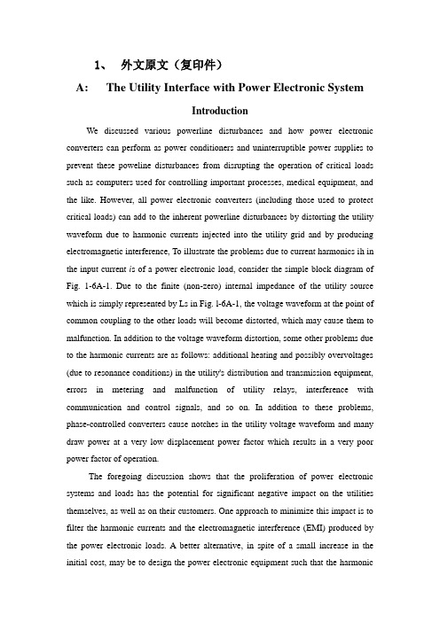
1、外文原文(复印件)A: The Utility Interface with Power Electronic SystemIntroductionWe discussed various powerline disturbances and how power electronic converters can perform as power conditioners and uninterruptible power supplies to prevent these poweline disturbances from disrupting the operation of critical loads such as computers used for controlling important processes, medical equipment, and the like. However, all power electronic converters (including those used to protect critical loads) can add to the inherent powerline disturbances by distorting the utility waveform due to harmonic currents injected into the utility grid and by producing electromagnetic interference, To illustrate the problems due to current harmonics ih in the input current i s of a power electronic load, consider the simple block diagram of Fig. 1-6A-1. Due to the finite (non-zero) internal impedance of the utility source which is simply represented by Ls in Fig. l-6A-1, the voltage waveform at the point of common coupling to the other loads will become distorted, which may cause them to malfunction. In addition to the voltage waveform distortion, some other problems due to the harmonic currents are as follows: additional heating and possibly overvoltages (due to resonance conditions) in the utility's distribution and transmission equipment, errors in metering and malfunction of utility relays, interference with communication and control signals, and so on. In addition to these problems, phase-controlled converters cause notches in the utility voltage waveform and many draw power at a very low displacement power factor which results in a very poor power factor of operation.The foregoing discussion shows that the proliferation of power electronic systems and loads has the potential for significant negative impact on the utilities themselves, as well as on their customers. One approach to minimize this impact is to filter the harmonic currents and the electromagnetic interference (EMI) produced by the power electronic loads. A better alternative, in spite of a small increase in the initial cost, may be to design the power electronic equipment such that the harmoniccurrents and the EMI are prevented or minimized from being generated in the first place. Both, the concerns about the utility interface and the design of power electronic equipment to minimize these concerns are discussed here.Generation of Current HarmonicsIn most power electronic equipment, such as switch-mode dc power supplies, uninterruptible power supplies (UPS), and ac and dc motor drives, ac-to-dc converters are used as the interface with the utility voltage source. Commonly, a line-frequency diode rectifier bridge as shown in Fig.1-6A-2 is used to convert line frequency ac into dc. The rectifier output is a dc voltage whose average magnitude Ud is uncontrolled.A large filter capacitor is used at the rectifier output to reduce the ripple in the dc voltage Ud. The dc voltage Ud and the dc current Id are unipolar and unidirectional, respectively. Therefore, the power flow is always from the utility ac input to the dc side. These line-frequency rectifiers with a falter capacitor at the dc side were discussed in detail in other section.A class of power electronic systems utilizes line-frequency thyristor-controlled ac-to-dc converters as the utility interface. In these converters, which were discussed in detail, the average dc output voltage Ud is controllable in magnitude and polarity, but the dc current Id remains unidirectional. Because of the reversible polarity of the dc voltage, the power flow through these converters is reversible. As was pointed out, the trend is to use these converters only at very high power levels, such as in high-voltage dc transmission systems. Because of the very high power levels, the techniques to ffdter the current harmonics and to improve the power factor of operation are quite different in these converters, as discussed in other section, than those for the line-frequency diode rectifiers.The diode rectifiers are used to interface with both the single-phase and the three-phase utility voltages. Typical ac current waveforms with minimal filtering were shown in other section. Typical harmonics in a single-phase input current waveform are listed in Table 1-6A-1, where the harmonic currents Ih are expressed as a ratio of the fundamental current Il. As is shown by Table 1-6A-l, such current waveformsconsist of large harmonic magnitudes. Therefore, for a finite internal per-phase source impedance Ls, the voltage distortion at the point of common coupling in Fig. 1-6A-1 can be substantial. The higher the internal source inductance Ls, the greater would be the voltage distortion.Current Harmonics and Power FactorAs we discussed in other section, the power factor PF at which an equipment operates is the product of the current ratio Il / Is and the displacement power factor DPF:In Eq. (1-6A-I), the displacement power factor equals the cosine of the angle Φ1. The current ratio Il / Is in Eq. (1-6A-l) is the ratio of the rms value of the fundamental frequency current component to the rms value of the total current. The power factor indicates how effectively the equipment draws power from the utility; at a low power factor of operation for a given voltage and power level, the current drawn by the equipment will be large, thus requiting increased volt-ampere ratings of the utility equipment such as transformers, transmission lines, and generators. The importance of the high power factor has been recognized by residential and office equipment manufacturers for their own benefit to maximize the power available from a wall outlet. For example from a 120V, 15A electrical circuit in a building, the maximum power available is 1.8 kW, provided the power factor is unity. The maximum power that can be drawn without exceeding the 15A limit decreases with decreasing power factor. The foregoing arguments indicate the responsibility and desirability on the part of the equipment manufacturers and users to design power electronic equipment with a high power factor of operation. This requires that the displacement power factor DPF should be high in Eq. (1-6A-I). Moreover, the current harmonics should be low to yield a high current ratio I1 / Is in Eq. (1-6A- 1).B: A Three-phase Pre-converter for Induction HeatingMOSFETBridge InvertersIntroductionHigh frequency power supplies, based on MOSFET bridge inverters, are already widely used for induction heating applications. These units require dc input voltages of about 400V to allow efficient operation of the MOSFETs employed. This supply voltage is usually obtained by using a three-phase rectifier stage, appropriate smoothing components or by employing thyristor phase- angle control to the mains supply. This kind of mains frequency power supply allows output power control of the induction heater, but it suffers from highly distorted input current waveforms with a low power factor. New legislation has been proposed to limit the maximum magnitude of harmonics drawn from the mains supply and different strategies have been suggested to reduce mains pollution.Investigations have been made to replace mains frequency power supplies by switched mode pre-converters. Switched mode converters can be designed to draw sinusoidal input currents thus avoiding the need for large and expensive mains frequency filters. At the same time these converters provide output power control and implementation of a small size high frequency isolation transformer. Power factor corrected three-phase ac-dc switched mode converter systems have usually been obtained using three identical single-phase converters with a common output filter. These systems overcome problems of mains pollution, but suffer from the disadvantage of a relatively large number of components and the need for complicated control and synchronization circuits. To reduce component costs, a structure based on a boost converter with three-phase input diode rectifier has been suggested. However, when operated direct-off-line from a three-phase 415V mains supply, this structure leads to high output voltages above lkV.In this paper, a novel method to achieve power factor correction for three-phase ac to dc power converters is described. The proposed topology is based on the buck converter and allows therefore output voltages to be below the maximum input voltage. The proposed topology utilizes a three- phase diode rectifier at the mains input and a single active switching device. The active switching device operates underzero-current switching conditions, resulting in very high converter efficiencies and low RFI emissions.Zero-current switching technique allows semiconductor devices to be operated at much higher switching frequencies and with reduced drive requirements compared with conventional switched mode operation.The proposed single-ended resonant converter with three-phase diode rectifier offers good opportunities for medium power, ac to dc applications. It combines simplicity and ease of control with high converter efficiency and high output power capabilities. It will be shown in the paper, that these characteristics make the converter very suitable as a direct replacement for the conventional mains frequency power supply used to supply induction heating MOSFET bridge inverters.General DescriptionA block diagram of the proposed induction heating system is shown in Fig. 1-6B-1. Block 1 represents the pre-converter that produces the dc supply voltage to feed to the RF MOSFET bridge inverter. Its output voltage should be controllable over a wide range to control the output power of the inverter and it must be able to operate with a wide range of load resistance to compensate load changes of the induction heating inverter stage. The pre-converter should operate direct-off-line from a three-phase 415V mains supply, drawing sinusoidal input current waveforms with a power factor approaching unity.Block 2 shows the RF MOSFET bridge inverter.The required maximum supply voltage of the MOSFET bridge lies between 300V and 400V. Block 3 represents the control and protection circuit used to stabilise the output power and to allow reliable operation of the induction heater in an industrial environment.Principle of Converter OperationA circuit diagram of the proposed three-phase ac to dc converter topology is shown in Fig. 1- 6B-2. The converter input currents are filtered through the input inductors L1, L2, L3. These inductors are designed so that the converter input currents are approximately constant over a whole switching cycle.During the OFF time of switch S, all three capacitors are charged by the inputcurrents I1, I2,I3. Consequently the three capacitor voltages Uc1, Uc1, Uc1 begin simultaneously to increase at a rate proportional to their respective input currents. If discontinuous operation is assumed the initial voltages of all capacitors C1, C2, C3 are zero when the switch ceases conducting. Hence, the peak voltage across each capacitor at the end of the OFF interval is proportional to their respective phase input current during the same OFF interval. Since capacitor voltages always begin at zero, it means that their average values during OFF time are linearly dependent on the phase input currents.During the ON time of switch S the energy stored in the three input capacitors C1, C2 and C3 is discharged through the six rectifier diodes VD1 –VD6, the switch S and the resonant inductor Lr. The rate of current decrease is dependent on the phase currents I1, I2, I3 and the switch current I0. The average value of the capacitor voltages Uc1, Uc2, Uc3 during the ON time are not linearly dependant on their phase input currents.To draw sinusoidal input currents from the mains supply the converter must draw input currents averaged over each switching cycle which are proportional to the phase voltages. Assuming steady state converter operation, the average phase input voltages over each switching cycle must be equal to the appropriate average input capacitor voltages during the switch OFF time plus the average input capacitor voltages during the switch ON time.Average input capacitor voltages during the switch OFF time have been shown to be proportional to the phase input currents, but during the switch ON time this is not true. However, if the switch ON time of the converter is mucteshorter than the switch OFF time, then the shape of the phase input currents will approach a sinusoidal waveform with unity power factor.2、外文资料翻译译文A:效用界面与电力电子系统介绍我们之前介绍了许多种电力线的干扰情况和电力系统转换器是如何在作为电力调节器和电力电子变换器时,用来防止那些电力线扰动干扰操作的临界荷载,例如电脑用于控制重要步骤,医疗设备,以及类似其他情况。
电力系统外文翻译
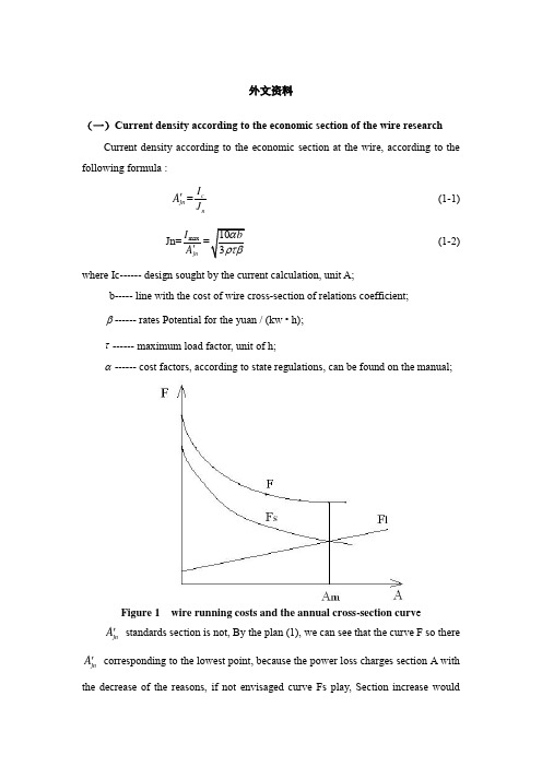
外文资料(一)Current density according to the economic section of the wire researchCurrent density according to the economic section at the wire, according to the following formula :jn A '=c nI J (1-1) Jn=max jn I A '(1-2) where Ic------ design sought by the current calculation, unit A; b----- line with the cost of wire cross-section of relations coefficient;β------ rates Potential for the yuan / (kw • h);τ------ maximum load factor, unit of h;α------ cost factors, according to state regulations, can be found on the manual;Figure 1 wire running costs and the annual cross-section curv ejn A ' standards section is not, By the plan (1), we can see that the curve F so there jn A ' corresponding to the lowest point, because the power loss charges section A with the decrease of the reasons, if not envisaged curve Fs play, Section increasewouldinevitably lead to the increase in operating costs. So admission standards section should not only satisfy the minimum requirements of the power loss, but also reduce running costs less because(1) In general, the establishment of factories or load a development process, the initial value is smaller than the design, gradually in order to achieve the expected A'network is completed by the load considered, This is not consistent value, butjnwith the actual situation, in other words, power loss is not designed so much to the imagination;(2) Design calculations indicate the actual load Ic than big design value;(3) F curve relatively flat bottom.A'smaller than Therefore, the selection criteria section, it should be by choicejnthe cross section, as F curve flat bottom, operating costs of less impact, taking into account the load values, as well as changes in the law, Theoretical calculation of the power loss will be larger than the actual value. with the options to save much of the initial investment and the consumption of non-ferrous metals.In the factory power supply system design using Jn wire cross section, Energy losses are still high volume of large factories into line and the electric network in the short occasions application. Method used Jn wire cross section still in use, but it should be noted that this method has the following problems :(1) 1.2 formula of the b value is not constant, the domestic tariff beta value is not uniform, Operating costs of Europium value in different countries should have the period of change.(2) This method is only from the operating expenses for at least the premise, not the investment, operating costs and the overall efficiency.Therefore, the proposed foreign books "at least expenditure," the wire cross section. Under Ic can elect to meet the heating requirements of the specifications 2-3 lead, their investment costs and operating costs are different. High investment costs of cross-section wire resistance by small and less power loss costs, it will be able to choose one of the best programs. But because the wire cross section Size is notcontinuous, but a broken line, in order to solve the lowest value to be used on the dogleg approximation method for the mathematical model, which is relatively more complicated, it has not been applied to engineering practice.(二)Grounding the researchCircuits are grounded in order to prevent high voltages from building up on the conductors, while equipment grounding aims at preventing enclosures from reaching voltages above ground. Grounding thus improves system protection and reliability and provides safety to people standing by.Grounding every circuit, however, makes the system susceptible to excessive currents should a short circuit develop between a live conductor and ground. Thus, not all neutrals of wye-connected loads (especially large motors) should be grounded. Grounding should then be practiced selectively, especially on the primary distribution system, as shown in Fig. -1. In part (a), disconnection of motors M1 and M3 for maintenance of repair deprives the 2400-volt system of a ground. It is preferable toground the system at the source, that is, at the transformer neutral in Fig.-1 (b).2400V13.8kVM1M2M3M4(a)2400V13.8kVM1M2M3M4(b)Fig.2 Circuit grounding done selectively(a) at a few motor neutrals (load);(b) at the transformer neutral (source)Metal enclosures,raceways,and fixed equipments are normally grounded. However,motor and generators well insulated from ground,and metal enclosurs used to protect cables or equipments from physical damage,may be left ungrounded.Aslo,portable tools and home appliances,such as refrigerators and air conditions,need not be grounded if constructed with double insulation.Some ac circuits are required to be ungrounded as,for instance,in anesthesizing locations in hospital.In fact,line isolation monitors are installed in such cases,capable of sounding warning signals.High-voltage services (>1000V) are not necessarily grounded, but they must be so if they supply portable equipment.Metal underground water pipes are normally used for grounding, If their length is judged inadequate, they may be complemented by other means, such as a building metal frame or some underground pipe of tank.中文译文(一)按照经济电流密度选择导线截面的研究按照经济电流密度选择导线截面时,可根据下式:jn A '=c nI J (1-1) Jn=max jn I A '(1-2) 式中 Ic------设计时求得的计算电流,单位为A ;b-----线路造价与导线截面间的关系系数; β------电价,电位为元/(kw·h)τ------最大负荷损耗系数,单位为h ;α------费用系数,根据国家规定,可在有关手册中查到;图1 导线截面与年运行费的关系曲线jn A '未必是标准截面,那么,由图 1可以看出,曲线F 所以出现对应于jn A '的最低点,是因为电能损耗费随截面A 的增大而减小的缘故,设想如果没有曲线Fs 起作用,截面的增加必然引起运行费用的增加。
配电系统无功补偿装置中英文对照外文翻译文献

中英文对照外文翻译(文档含英文原文和中文翻译)Optimization of reactive power compensation indistribution systemThe reactive power compensation for distribution network,as the supplement of substation compensation can effectively improve the power factor, reduce line loss, improve the end voltage, ensure the quality of power supply, also bring good economic benefits for enterprise, has received extensive attention. The distributed reactive compensation, installing power capacitors on feeders, is the main distribution network compensation mode at home and abroad [1], but different installed location and different installed capacity, the benefit is different. With the application of reactive power compensation distribution increase gradually, how to choose appropriate reactive compensation location and compensation capacity to make the maximum benefit with less cost become people's research target. And the optimization of distributed reactive compensation of distribution network was raised .At present, the decision of the best compensation capacity and the best position in actual distribution reactive compensation, usually in accordance with ideal situations, such as, the reactive load along the road distributed uniformly, increasing, diminishing distribution or as isosceles distribution, and so on [2], [9]. This method has clear results, simple calculation, and has a certain engineering practical value. But the actual reactive load distribution is more complex, which is different from the ideal situation. So, in accordance with ideal situations to premise reactive compensation configuration optimization formula may be not satisfied. To study a more general distributed reactive compensation configuration optimized method is needed.This paper studies several kinds of typical optimal allocation of reactive compensation configuration with ideal load distribution. Then it details the distributed reactive compensation optimized mathematical model,- 11 -which is applied to any load distribution or distribution network structure, and gives the effective algorithm. At last, the paper introduces the practical application of the research of the model and the algorithm.The ideal load distribution is refers to the reactive power load distributed along the line meet a kind of ideal regular distribution, for example, in any point the road reactive load is equal, named uniform distribution, the reactive load from the first end increasing or decreasing, named increasing or decreasing distribution, and so on. This is an abstract of the actual load distribution, and in such a hypothesis premise the analytical expressions of the optimal location and capacity can be deduced, which can get the best reduce loss effect. And the results are showed in Table I and Fig 1, which can be chose in practical projects [3], [4], [6].When the actual power distribution is different from the ideal situation, using the results to guide the reactive compensation configuration, the effect may be not beautiful. It needs to study a more general reactive compensation configuration optimized method.The optimization of distribution network distributed reactive compensation is distributed as a mixed integer nonlinear optimization problems, which is to determine the reactive compensation position and capacity with some constraints [5]. Therefore, the compensation position and capacity are the two decision variables. Its mathematical model is a two layers optimized problem with constraint. First is the capacity optimization at determined location, second is the distribution optimization. Based on the optimization mathematical model and algorithm, the corresponding graphical calculation software has been developed. With the optimization results, some power capacitors are installed on ten lOkV rural feederswhich had lower power factor and higher line loss. And the actual operation showed good effect. As shown in Fig 3 and Table II, it is the optimization of a feeder named CHANG 7.the total length is 22.35 km, the conductor type of trunk line is LGJ-120,with a distribution capacity of 4760 kVA. The active power- 12 -was 1904 kW, and the power factor was 0.83. The objective power factor was set at 0.9, so the reactive compensation total capacity was 358 kvar. The parameters including length and conductor type of each section, nameplate parameters of transformers, and the reactive compensation total capacity were set in the graphical software. Yet, the graph of the feeder had been drawn too. Then the results were marked on the feeder graph automatically, such as Fig. 3.As shown in Table II, theory line loss rate got an obvious 0.4149 percents decrement, if reactive compensation devices were installed. Also, under the condition of total capacity, two installations made 0.007 percent lower than one, and three points installation made 0.0003 percent lower than two. Then more compensation installations got more decrement of theory line loss rate, but the decreasing rate become inconspicuous, In contrast, equipment maintenance cost increased a lot. Therefore, two installations were selected onCHANG 7 feeder at last.This work provides scientific and reasonable theory for reactive power optimization of distribution network, and gives a reference for the distribution network loss calculation. Also, it provides the convenience for improving the quality of voltage, energy saving and improving line loss management level.1) For solving distribution network reactive power optimization problem, this paper puts forward the double optimization mathematical model of distribution network distributed reactive compensation, the inner is compensation capacity optimization, the outer layer is the reactive compensation distribution optimization. The model can do distribution reactive compensation optimization with any load distribution and arbitrary distribution network structure forms.2) By introducing Lagrange multiplier and the necessary condition of extreme, the mixed integer nonlinear optimization problem is deduced to a linear one that can be easily solved by Gaussian elimination method. It is- 13 -very imple and efficient for computer programming.3) The model and the algorithm can give different optimized results and loss reduction for different number of capacitor installation. Engineering practice showed that optimized capacitors installation can make line loss rate get an obvious decrement. This research plays an important role in the actual reactive compensation equipment installation of distribution network and line loss management.Reasonable reactive power sources compensation of rural substations h as been becoming a hot issue since Chinese rural electric network alteration. The principal reactive power compensation mode of rural substations is still using fixed compensation capacitor to control voltage and reactive power at present in China. This compensation mode has some problems. such as capacity adjustment requires manual intervention under power outage, the phenomenon of over and under compensation may always happen, the rate of putting into operation of reactive power compensation is relatively low, and so on . At the same time, there is no sampling function at the primary side of the main transformer because of the special devices in rural substations. In order to realize the objectives that the power factor is not less than 0.95 at primary side and not less than 0.9 at secondary side at the highest load, in this paper,some optimal reactive power control strategies for rural substation were proposed. In accordance with the reactive power flow conditions of the rural distribution network , the pros and cons of two control strategies were analyzed. One of the strategies was sampling at the primary side of the main transformer , the other was sampling at the s econdary side and switching control by power factor of secondary side. After comparison of such analysis, an optimal control strategy was p roposed. The data were sampledin the substation secondary side, then t he sampled data were evaluated in equivalence to the primaryside, and then the power factor assessment criteria of primary side were used t o control capacitor switching . The compensation capacity should be c- 14 -alculatedafter electric motor compensation , transformer compensation an d distributed compensation on distribution line.The sampled values at se condary side and active loss and reactive loss of themaintransformer w ere used to calculate compensation capacity to meet the power factor o bjectives of primary side. Through the example calculation and analysiby Applying actual substation data a result were obtained.The result met ap praisal standards and the power factor of main transformer primary sid e was above 0.95 at the highest load . If the power factor of main tran sformer secondary side was above 0.98 , there was no need to co mpensate for substation . If the power factor of main transformer secondaryside was under 0.97,after the compensation by using the p roposed optimal compensation capacity and the primary side power f actor control method, the power facto r of the main transformer se condary side was not less than0.98 and the primary side reaches 0.95. T hese results show that the proposed optimal control strategy and compe nsation capacity calculation method are feasible, and the research haspra ctical significance of making full use of reactive power supply in rural di stribution network.Optimal allocation of reactive power compensation plays an important role in power system planning and design. However, as a non-linear, larg e scale combinatorial . optimization problem, Conventional methods are not normally appropriate for it.A mathematical model is firstly presented in this paper for comprehensive optimal configuration in distribution feeders based on the analysis of engineering factors of reactive power compensation, whose objective is to minimize the annual expenditure involving the devices investment and the income of energy saving, and satisfy all sorts of operation ,fixing and maintenance constrains . The control variable include the capacitor banks’number and capacity of various compensation schemes. RARW-GA algorithm is adopted to solve this problem.The result of calculation and analysis of BenXi Steel group c orporation power system shows that the proposed method is feasible- 15 -and effective.An improved TS algorithm is put forward on the condition that reactive power compensation location and capacity have been identified in rural distribution lines. The Algorithm is based on capacitor optimal on-off model aimed at a minimum network loss, it can control the capacitor on-off according to the load changing and the system operation status and keep real-time voltage qualified and network loss minimum. A distributed control system is designed by using the algorithm to realize reactive power optimization, which is composed of reactive power optimal terminals and background control center. The terminal is in charge of data collection and transmission, on-off instruction receiving and executing. The control center in in charge of receiving data from every compensation point, calling control algorithm to process data, forming and sending instructions. GPRS technology is adopted to realize the system’s foreground-background communication. The actual application in some experimental networks has proved that the system can realize global optimal control for distribution lines, and is suitable to be widely used in rural distribution network.In order to solve the optimization of distribution reactive compensation point and capacity, a double optimized model is proposed, which is sui able for reactive compensation optimizationwith random load distribution or random network structure. For the compensation position and capacity decision variables, the optimized model is described as two layers of optimization with constraint . The outer one is the capacity optimization at determined location , and the inlayer is the location optimization . By introducing Lagrange multiplier, the mixed integer nonlinear optimization is deduced to a linearone that can be easily solve by Gaussian elimination method. For illustration, an application of ten 10kV rural feeders is utilized to show the feasibility of the double optimized model in solving the optimization of distribution reactive compensation point and capacity. Empirical results show that the model can give the optimized result for different number of capacitor installa-- 16 -tion, and the result with highest line loss decrementwill be used as thefi nal decision.The research provides scientific theoretical basis for Reactive compensation and plays a vital role in reactive compensation equipment installation and line loss management.Taking account of the mutual impacts of distributed generation and reactive power , to determine the optimal position and capacity of the compensation device to be installed , the paper proposed an improved Tabu search algorithm for reactive power optimiza-tion . The voltage q uality is considered of the model using minimum network active power l oss as objective Function . It is achieved by maintaining the whole s ystem power lossa minimum thereby reducing cost allocation. On the ba sis of general Tabu search algorithm , the algorithm used memory gu idance search strategy to focus on searching for a local optimum va lue, avoid a global search blindness . To deal with the neighborhood so lution set properly or save algorithm storage space,some corresponding i mprovments are made, thus, it is easily to stop the iteration of partial optimization and it is more probable to achieve the global optimizationb y use of the improved algorithm.Simulations are carried out on standard IEEE 33 test system and results are presented.SupSuperconducting Magnetic Energy Storage SMES) can inject or absorb real and reactive power to or from a power system at a very fast rate on a repetitive basis. These characteristics make the application of SMES ideal for transmission grid control and stability enhancement. Superconducting Magnetic Energy Storage SMES) is an attractive apparatus for some power system applications because it is capable of leveling load demand with high efficiency, compensating for load changes, maintaining a bus voltage, and stabilizing power swings. Power system stability problems have attracted the attention of power system engineers for several decades. Considerable progress has been made on excitation control, governor control, control by static var compensator, etc. Modern power systems, which are growing in size and complexity, are characterized by long distance bulk power transmissions and- 17 -wide area interconnections.In such power systems, undamped power swings of low frequency can occur. This can be a serious problem since the instability often decreases the power transmission capacity. As a result, the power that can be transmitted in steady state and transient situations is limited. If the limit is exceeded, the generator loses synchronous operation and system instabilities occur. SMES may be an effective means of preventing these instabilities, thereby maximizing power transfer to meet increased load demand. A SMES system can be represented in dynamic simulations as a continuous controllable real and reactive power source. In steady-state simulations, SMES can be represented as a continuous controllable reactive power source since it can continuously operate throughout its range of reactive power. However, the output of real power from a SMES device is limited to the amount of energy stored in the coil. The first objective of this research is to determine the optimal internal control scheme needed to decide the controllable active and reactive power based on active and reactive power demanded by the power system. The second objective is to design and simulate SMES external control models which are dependent on the network configuration. The third objective is to determine how the optimal size of a SMES device varies for a given transient stability disturbance when alternative internal control models and external control models are used.With a big number of electric energy consumers and different characters electric energy quality depends on many factors in the modern power networks. It includes: power networks and working condition factors of consumers. One of them is the possibility of reactive power balances with an important reserve providing after emergency modes on the basic knots of the power system and voltage regulation on all networks.As the length of networks of a power system increases in modern conditions, we can reduce the reactive power streams, as well as operational and capital expenses. Rational voltage mode brings to the front plan the- 18 -technical一economic aspects of the power transmission EFFICIENCY. Analyses and economic calculations show that transferring the reactive power by short length lines means of a high voltage justifies. Therefore in most cases reduction of reactive power to the minimum is very effective for economically when the sources of reactive power settle down near the consumption centers.The increase of consumer loading and its structure qualitative causes considerable increase of reactive power and constant reduction of a power factor in distributed power networks [ 1」.Thus, the tendency of modern power systems development is characterized by one side with the increase of reactive power consumption (in some systems to 1 kVAR/kVt), on the other side with decrease of power plant generators usage expediency and possibility for the reactive power compensation purpose [2-5]. In such conditions reactive power compensation attains a specialurgency. Here the optimization's primary goal is optimum placing of reactive power sources andsupport of a necessary reserve of capacity QreZ for voltage regulation on loading knot. For example, Polish power engineers consider that capacity of compensators should be 50% of the established capacity of generators in power plants. In France, Sweden and Germany the capacity of compensators is 35% of active peak loading, in the USA and Japan this volume is 70%. In different power systems of the USA the established capacity of compensators is 100% of generators capacities [6-11].Reactive power compensation problem is a multidimensional problem on the technical andeconomic aspects and consequently it is resulted with the finding of a global extremum of criterion function with the set of local extreme. In this article the voltage support within the technical restrictions and definition of optimal placing of the reactive power sources with a technique of multi-purpose- 19 -optimization of reactive power in the power system is considered. By the problem consideration as one-target optimization within restrictions the criterion function is a linear combination from several factors. The problem decision is a unique optimum version and has lacks of alternative versions, and there is not dependency of an end result from the initial data.Thus, the purpose of reactive power sources optimal placing in a power system consists ofincrease the quality of voltage in all central points of a network, control the stability of the system, reduce the power losses and capacities in networks. As a result these will increase the economic efficiency in the power system. From the economic efficiency point of view the new compensating units intended for installation should be proved and given corresponding optimum recommendations.1 .Methods and multi-purpose optimization compensations algorithms have been developed with support of a necessary reserve for preservation of normal level of voltage taking into account technical restrictions in knots of an electric network of a power system. Results of computerization to realization have shown speed and high efficiency the developed algorithm providing minimization of losses of active capacity in a net.2. Based on genetic algorithm the power and installation locations of the static capacitor banks with the multicriteria optimization technique has given. In this case, as a criterion of optimality the minimum expenses for the installation and exploitation, the minimization of power losses during the required values of voltage and power factor and maximum saving and the minimum self-payment term are accepted.3. The report of the real electricity network is given for two cases: operation without the CB;with optimal placement of CB. The application of the proposed method can reduce the averagepower losses approximately 13一14% in the electric network.- 20 -配电系统无功补偿装置容量优化配电网无功补偿,作为补充的变电站补偿可以有效地提高功率因数,减少线路损耗,提高末端电压,保证供电质量,也能带来良好的企业的经济效益,已得到泛的注意。
电力系统继电保护外文及翻译
Power System ProtectionsThe steady-state operation of a power system is frequently disturbed by various faults on electrical equipment. To maintain the proper operation of the power system, an effective, efficient and reliable protection scheme is required. Power system components are designed to operate under normal operating conditions.However, due to any reason, say a fault, there is an abnormality, it is necessary that there should be a device which senses these abnormal conditions and if so, the element or component where such an abnormality has taken place is removed, i.e. deleted from the rest of the system as soon as possible. This is necessary because the power system component can never be designed to withstand the worst possible conditions due to the fact that this will make the whole system highly uneconomical. And therefore, if such an abnormality takes place in any element or component of the power system network, it is desirable that the affected element/component is removed from the rest of the system reliably and quickly in order to restore power in the remaining system under the normal condition as soon as possible.The protection scheme includes both the protective relays and switching circuits, i.e. circuit breakers. The protective relay which functions as a brain is a very important component. The protective relay is a sensing device, which senses the fault, determines its location and then sends command to the proper circuit breaker by closing its trip coil. The circuit breaker after getting command from the protective relay disconnects only the faulted element. this is why the protective relay must be reliable, maintainable and fast in operation.In early days, there used to be electromechanical relay of induction disk-type.However, very soon the disk was replaced by inverted cup, i.e.hollow cylinder and the new relay obtained was known as an induction cup or induction cylinder relay. This relay, which is still in use, possesses several important features such as higher speed; higher torque for a given power input an more uniform torque.However, with the advent of electronic tubes, electronic relays having distinct features were developed during 1940s. With the discovery of solid state components during 1950s, static relays with numerous advantages were developed. The use of digital computers for protective relaying purposes has been engaging the attention of research and practicing engineers since layer 1960s and 1980s. Now, the microprocessor/mini computer-based relaying scheme, because of its numerous advantages such as self –checking feature and flexibility, has been widely used in power system all over the world.The overall system protection is divided into following sections: (i)Generator protection,(ii)Transformer protection,(iii)Bus protection,(iv)Feederprotection,(v)Transmission line protection.Basic Requirements to Protective RelaysAny protection scheme, which i.e. required to safeguard the power system components against abnormal conditions such as faults, consists basically of two elements(i)Protective relay and (ii) Circuit breaker .The protective relay which is primarily the brain behind the whole scheme plays a very important role. Therefore proper care should be taken in selecting an appropriate protective relay which is reliable, efficient and fast in operation. The protective relay must satisfy the following requirements:⑴ since faults on a well designed and healthy system are normally rare, therelays are called upon to operate only occasionally. This means that therelaying scheme is normally idle and must operate whenever fault occurs. Inother words, it must be reliable.⑵ Since the reliability partly depends upon the maintenance, the relay mustbe easily maintainable.⑶ The palpation of the relay can be in two ways. One is the failure to operatein case a fault occurs an second is the relay operation when there is no fault.As a matter of fact, relay must operate if there is a fault and must notoperate if there is no fault.⑷Relaying scheme must be sensitive enough to distinguish between normaland the faulty system.Protective RelaysThe function of the protective relay is to sense the fault and energize the tripcoil of the circuit breaker. The following types of the protective relays are usedfor the apparatus such as synchronous machines, bus bar, transformer and the other apparatus and transmission line protection.(1) Over current relays,(2) Under voltage relays,(3) Under frequency relays,(4) Directional relays,(5) Thermal relays,(6) Phase sequence relays such as(i)negative sequence relays and, (ii)zerosequence relays,(7) Differential relays and percentage differential relays,(8) Distance relays such as (I)plane impedance relays,(ii)angle impedance relay,i.e. Ohm or reactance relays,(iii)angle admittance relays,i.e. Mho relaysand ,(iv)offset and restricted relays,(9)Pilot relays such as (i) wire pilot relays,(ii)carrier channel pilotrelays,(iii)microwave pilot relays. There are different types of the relayingscheme based on construction. They are:(i)electromechanicaltype,(ii)thermal relays,(iii) transduction relays,(iv)rectifier bridgerelay,(v)electronic relays,(vi)digital relaying schemes.电力系统继电保护电力系统的稳态运行经常会因各种电力设备配故障原因而被扰乱。
供配电系统中英文对照外文翻译文献
中英文对照外文翻译文献(文档含英文原文和中文翻译)POWER SUPPLY AND DISTRIBUTION SYSTEMABSTRACTThe basic function of the electric power system is to transport the electric power towards customers. The l0kV electric distribution net is a key point that connects the power supply with the electricity using on the industry, business and daily-life. For the electric power, allcostumers expect to pay the lowest price for the highest reliability, but don't consider that it's self-contradictory in the co-existence of economy and reliable.To improve the reliability of the power supply network, we must increase the investment cost of the network construction But, if the cost that improve the reliability of the network construction, but the investment on this kind of construction would be worthless if the reducing loss is on the power-off is less than the increasing investment on improving the reliability .Thus we find out a balancepoint to make the most economic,between the investment and the loss by calculating the investment on power net and the loss brought from power-off.KEYWARDS:power supply and distribution,power distribution reliability,reactive compensation,load distributionTEXTThe revolution of electric power system has brought a new big round construction,which is pushing the greater revolution of electric power technique along with the application of new technique and advanced equipment. Especially, the combination of the information technique and electric power technique, to great ex- tent, has improved reliability on electric quality and electric supply. The technical development decreases the cost on electric construction and drives innovation of electric network. On the basis of national and internatio- nal advanced electric knowledge, the dissertation introduces the research hotspot for present electric power sy- etem as following.Firstly, This dissertation introduces the building condition of distribution automation(DA), and brings forward two typical construction modes on DA construction, integrative mode and fission mode .It emphasize the DA structure under the condition of the fission mode and presents the system configuration, the main station scheme, the feeder scheme, the optimized communication scheme etc., which is for DA research reference.Secondly, as for the (DA) trouble measurement, position, isolation and resume, This dissertation analyzes the changes of pressure and current for line problem, gets math equation by educing phase short circuit and problem position under the condition of single-phase and works out equation and several parameter s U& , s I& and e I& table on problem . It brings out optimized isolation and resume plan, realizes auto isolation and network reconstruction, reduces the power off range and time and improves the reliability of electric power supply through problem self- diagnoses and self-analysis. It also introduces software flow and use for problem judgement and sets a model on network reconstruction and computer flow.Thirdly, electricity system state is estimated to be one of the key techniques in DA realization. The dissertation recommends the resolvent of bad measurement data and structure mistake on the ground of describing state estimate way. It also advances a practical test and judging way on topology mistake in state estimate about bad data test and abnormity in state estimate as well as the problem and effect on bad data from state measure to state estimate .As for real time monitor and control problem, the dissertation introduces a new way to solve them by electricity break and exceptional analysis, and the way has been tested in Weifang DA.Fourthly, about the difficulty for building the model of load forecasting, big parameter scatter limit and something concerned, the dissertation introduces some parameters, eg. weather factor, date type and social environment effect based on analysis of routine load forecasting and means. It presents the way for electricity load forecasting founded on neural network(ANN),which has been tested it’s validity by examp le and made to be good practical effect.Fifthly, concerning the lack of concordant wave on preve nting concordant wave and non-power compensation and non-continuity on compensation, there is a topology structure of PWM main circuit and nonpower theory on active filter the waves technique and builds flat proof on the ground of Saber Designer and proves to be practical. Meanwhile, it analyzes and designs the way of non-power need of electric network tre- nds and decreasing line loss combined with DA, which have been tested its objective economic benefit throu- gh counting example.Sixthly, not only do the dissertation design a way founded on the magrginal electric price fitted to our present national electric power market with regards to future trends of electric power market in China and fair trade under the government surveillance, that is group competitio n in short-term trade under the way of grouped price and quantityharmony, but also puts forward combination arithmetic, math model of trading plan and safty economical restriction. It can solve the original contradiction between medium and long term contract price and short term competitive price with improvement on competitive percentage and cut down the unfair income difference of electric factory, at the same time, it can optimize the electric limit for all electric factories and reduce the total purchase charge of electric power from burthen curve of whole electric market network.The distribution network is an important link among the power system. Its neutral grounding mode and operation connects security and stability of the power system directly. At the same time, the problem about neutral grounding is associated with national conditions, natural environment, device fabrication and operation. For example, the activity situation of the thunder and lightning, insulating structure and the peripheral interference will influence the choice of neutral grounding mode Conversely, neutral grounding mode affects design, operation, debugs and developing. Generally in the system higher in grade in the voltage, the insulating expenses account for more sizable proportion at the total price of the equipment. It is very remarkable to bring the economic benefits by reducing the insulating level. Usually such system adopt the neutral directly grounding and adopt the autoreclosing to guarantee power supply reliability. On the contrary, the system which is lower in the voltage adopts neutral none grounding to raise power supply reliability. So it is an important subject to make use of new- type earth device to apply to the distribution network under considering the situation in such factors of various fields as power supply reliability, safety factor, over-voltage factor, the choice of relay protection, investment cost, etc.The main work of this paper is to research and choice the neutral grounding mode of the l0kV distribution network. The neutral grounding mode of the l0kV network mainly adopts none grounding, grounding by arc suppressing coil, grounding by reactance grounding and directly grounding. The best grounding mode is confirmed through the technology comparison. It can help the network run in safety and limit the earth electric arc by using auto-tracking compensate device and using the line protection with the detection of the sensitive small ground current. The paper introduces and analyzes the characteristic of all kind of grounding modes about l0kV network at first. With the comparison with technological and economy, the conclusion is drawn that the improved arc suppressing coil grounding mode shows a very big development potential.Then, this paper researches and introduces some operation characteristics of the arc suppressing coil grounding mode of the l0kV distribution network. And then the paper putemphasis on how to extinguish the earth electric arc effectively by utilizing the resonance principle. This paper combines the development of domestic and international technology and innovative achievement, and introduces the computer earth protection and autotracking compensate device. It proves that the improved arc suppressing coil grounding mode have better operation characteristics in power supply reliability, personal security, security of equipment and interference of communication. The application of the arc suppressing coil grounding mode is also researched in this paper.Finally, the paper summarizes this topic research. As a result of the domination of the arc suppressing coil grounding mode, it should be more popularized and applied in the distribution network in the future.The way of thinking, project and conclusions in this thesis have effect on the research to choose the neutral grounding mode not only in I0kV distribution network but also in other power system..The basic function of the electric power system is to transport the electric power towards customers. The l0kV electric distribution net is a key point that connects the power supply with the electricity using on the industry, business and daily-life. For the electric power, all costumers expect to pay the lowest price for the highest reliability, but don't consider that it's self-contradictory in the co-existence of economy and reliable. To improve the reliability of the power supply network, we must increase the investment cost of the network con- struction But, if the cost that improve the reliability of the network construction, but the investment on this kind of construction would be worthless if the reducing loss is on the power-off is less than the increasing investment on improving the reliability .Thus we find out a balance point to make the most economic, between the investment and the loss by calculating the investment on power net and the loss brought from power-off. The thesis analyses on the economic and the reliable of the various line modes, according to the characteristics various line modes existed in the electric distribution net in foshan..First, the thesis introduces as the different line modes in the l0kV electric distribution net and in some foreign countries. Making it clear tow to conduct analyzing on the line mode of the electric distribution net, and telling us how important and necessary that analyses are.Second, it turns to the necessity of calculating the number of optimization subsection, elaborating how it influences on the economy and reliability. Then by building up the calculation mode of the number of optimization subsection it introduces different power supply projects on the different line modes in brief. Third, it carries on the calculation andanalyses towards the reliability and economy of the different line modes of electric distribution net, describing drafts according by the calculation. Then it makes analysis and discussion on the number of optimization subsection.At last, the article make conclusion on the economy and reliability of different line modes, as well as, its application situation. Accordion to the actual circumstance, the thesis puts forward the beneficial suggestion on the programming and construction of the l0kV electric distribution net in all areas in foshan. Providing the basic theories and beneficial guideline for the programming design of the lOkV electric distribution net and building up a solid net, reasonable layout, qualified safe and efficiently-worked electric distribution net.References[1] Wencheng Su. Factories power supply [M]. Machinery Industry Publishing House. 1999.9[2] Jiecai Liu. Factories power supply design guidance [M]. Machinery Industry Publishing House.1999.12[3] Power supply and distribution system design specifications[S].China plans Press. 1996[4] Low-voltage distribution design specifications [S].China plans Press. 1996.6供配电系统摘要电力系统的基本功能是向用户输送电能。
变电站中英文资料对照外文翻译文献综述
变电站中英文资料对照外文翻译文献综述XXXns are an essential part of electrical power systems。
servingas the interface een high-voltage n lines and lower-voltage n lines。
They play a critical role in XXX homes。
businesses。
and industries.Types of nsThere are several types of ns。
including n ns。
n ns。
and customer XXX to the end-users and step down the voltage for n to XXX a single customer or group of customers.XXXns consist of us components。
including transformers。
circuit breakers。
switches。
XXX are used to step up or step down thevoltage of the electricity。
XXX are used to control the flow ofXXX to the system.XXXXXX stages。
including site n。
layout design。
equipment n。
XXX n lines。
land availability。
and environmental ns。
The layout design involves determining the placement of equipment。
XXX appropriate transformers。
circuit breakers。
and other components。
开关电源中英文对照外文翻译文献

开关电源中英文对照外文翻译文献(文档含英文原文和中文翻译)Modeling, Simulation, and Reduction of Conducted Electromagnetic Interference Due to a PWM Buck Type Switching Power Supply IA. FarhadiAbstract:Undesired generation of radiated or conducted energy in electrical systems is called Electromagnetic Interference (EMI). High speed switching frequency in power electronics converters especially in switching power supplies improves efficiency but leads to EMI. Different kind of conducted interference, EMI regulations and conducted EMI measurement are introduced in this paper. Compliancy with national or international regulation is called Electromagnetic Compatibility (EMC). Power electronic systems producers must regard EMC. Modeling and simulation is the first step of EMC evaluation. EMI simulation results due to a PWM Buck type switching power supply are presented in this paper. To improve EMC, some techniques are introduced and their effectiveness proved by simulation.Index Terms:Conducted, EMC, EMI, LISN, Switching SupplyI. INTRODUCTIONFAST semiconductors make it possible to have high speed and high frequency switching in power electronics []1. High speed switching causes weight and volume reduction of equipment, but some unwanted effects such as radio frequency interference appeared []2. Compliance with electromagnetic compatibility (EMC) regulations is necessary for producers to present their products to the markets. It is important to take EMC aspects already in design phase []3. Modeling and simulation is the most effective tool to analyze EMC consideration before developing the products. A lot of the previous studies concerned the low frequency analysis of power electronics components []4[]5. Different types of power electronics converters are capable to be considered as source of EMI. They could propagate the EMI in both radiated and conducted forms. Line Impedance Stabilization Network (LISN) is required for measurement and calculation of conducted interference level []6. Interference spectrum at the output of LISN is introduced as the EMC evaluation criterion []7[]8. National or international regulations are the references for the evaluation of equipment in point of view of EMC []7[]8.II. SOURCE, PATH AND VICTIM OF EMIUndesired voltage or current is called interference and their cause is called interference source. In this paper a high-speed switching power supply is the source of interference.Interference propagated by radiation in area around of an interference source or by conduction through common cabling or wiring connections. In this study conducted emission is considered only. Equipment such as computers, receivers, amplifiers, industrial controllers, etc that are exposed to interference corruption are called victims. The common connections of elements, source lines and cabling provide paths for conducted noise or interference. Electromagnetic conducted interference has two components as differential mode and common mode []9.A. Differential mode conducted interferenceThis mode is related to the noise that is imposed between different lines of a test circuit by a noise source. Related current path is shown in Fig. 1 []9. The interference source, path impedances, differential mode current and load impedance are also shown in Fig. 1.B. Common mode conducted interferenceCommon mode noise or interference could appear and impose between the lines, cables or connections and common ground. Any leakage current between load and common ground could be modeled by interference voltage source.Fig. 2 demonstrates the common mode interference source, common mode currents Iandcm1 and the related current paths[]9. The power electronics converters perform as noise source Icm2between lines of the supply network. In this study differential mode of conducted interference is particularly important and discussion will be continued considering this mode only.III. ELECTROMAGNETIC COMPATIBILITY REGULATIONS Application of electrical equipment especially static power electronic converters in different equipment is increasing more and more. As mentioned before, power electronics converters are considered as an important source of electromagnetic interference and have corrupting effects on the electric networks []2. High level of pollution resulting from various disturbances reduces the quality of power in electric networks. On the other side some residential, commercial and especially medical consumers are so sensitive to power system disturbances including voltage and frequency variations. The best solution to reduce corruption and improve power quality is complying national or international EMC regulations. CISPR, IEC, FCC and VDE are among the most famous organizations from Europe, USA and Germany who are responsible for determining and publishing the most important EMC regulations. IEC and VDE requirement and limitations on conducted emission are shown in Fig. 3 and Fig. 4 []7[]9.For different groups of consumers different classes of regulations could be complied. Class A for common consumers and class B with more hard limitations for special consumers are separated in Fig. 3 and Fig. 4. Frequency range of limitation is different for IEC and VDE that are 150 kHz up to 30 MHz and 10 kHz up to 30 MHz respectively. Compliance of regulations is evaluated by comparison of measured or calculated conducted interference level in the mentioned frequency range with the stated requirements in regulations. In united European communitycompliance of regulation is mandatory and products must have certified label to show covering of requirements []8.IV. ELECTROMAGNETIC CONDUCTED INTERFERENCE MEASUREMENTA. Line Impedance Stabilization Network (LISN)1-Providing a low impedance path to transfer power from source to power electronics converter and load.2-Providing a low impedance path from interference source, here power electronics converter, to measurement port.Variation of LISN impedance versus frequency with the mentioned topology is presented inFig. 7. LISN has stabilized impedance in the range of conducted EMI measurement []7.Variation of level of signal at the output of LISN versus frequency is the spectrum of interference. The electromagnetic compatibility of a system can be evaluated by comparison of its interference spectrum with the standard limitations. The level of signal at the output of LISN in frequency range 10 kHz up to 30 MHz or 150 kHz up to 30 MHz is criterion of compatibility and should be under the standard limitations. In practical situations, the LISN output is connected to a spectrum analyzer and interference measurement is carried out. But for modeling and simulation purposes, the LISN output spectrum is calculated using appropriate software.For a simple fixed frequency PWM controller that is applied to a Buck DC/DC converter, it is) changes slow with respect to the switching frequency, the possible to assume the error voltage (vepulse width and hence the duty cycle can be approximated by (1). Vp is the saw tooth waveform amplitude.A. PWM waveform spectral analysisThe normalized pulse train m (t) of Fig. 8 represents PWM switch current waveform. The nth pulse of PWM waveform consists of a fixed component D/fs , in which D is the steady state duty cycle, and a variable component dn/f sthat represents the variation of duty cycle due to variation of source, reference and load.As the PWM switch current waveform contains information concerning EMI due to powersupply, it is required to do the spectrum analysis of this waveform in the frequency range of EMI studies. It is assumed that error voltage varies around V e with amplitude of V e1as is shown in (2).fm represents the frequency of error voltage variation due to the variations of source, reference and load. The interception of the error voltage variation curve and the saw tooth waveform with switching frequency, leads to (3) for the computation of duty cycle coefficients []10.Maximum variation of pulse width around its steady state value of D is limited to D1. In each period of Tm=1/fm , there will be r=fs/fm pulses with duty cycles of dn. Equation (4) presents the Fourier series coefficients Cn of the PWM waveform m (t). Which have the frequency spectrum of Fig.9.B-Equivalent noise circuit and EMI spectral analysisTo attain the equivalent circuit of Fig.6 the voltage source Vs is replaced by short circuit and) as it has shown in Fig. 10. converter is replaced by PWM waveform switch current (IexThe transfer function is defined as the ratio of the LISN output voltage to the EMI current source as in (5).The coefficients di, ni (i = 1, 2, … , 4) c orrespond to the parameters of the equivalent circuit. Rc and Lc are respectively the effective series resistance (ESR) and inductance (ESL) of the filter capacitor Cf that model the non-ideality of this element. The LISN and filter parameters are as follows: CN = 100 nF, r = 5 Ω, l = 50 uH, RN =50 Ω, LN=250 uH, Lf = 0, Cf =0, Rc= 0, Lc= 0, fs =25 kHzThe EMI spectrum is derived by multiplication of the transfer function and the source noise spectrum. Simulation results are shown in Fig. 11.VI. PARAMETERS AFFECTION ON EMIA. Duty CycleThe pulse width in PWM waveform varies around a steady state D=0.5. The output noise spectrum was simulated with values of D=0.25 and 0.75 that are shown in Fig. 12 and Fig. 13. Even harmonics are increased and odd ones are decreased that is desired in point of view of EMC.On the other hand the noise energy is distributed over a wider range of frequency and the level of EMI decreased []11.B. Amplitude of duty cycle variationThe maximum pulse width variation is determined by D1. The EMI spectrum was simulatedwith D1=0.05. Simulations are repeated with D1=0.01 and 0.25 and the results are shown in Fig.14and Fig.15.Increasing of D1 leads to frequency modulation of the EMI signal and reduction in level ofconducted EMI. Zooming of Fig. 15 around 7thcomponent of switching frequency in Fig. 16shows the frequency modulation clearly.C. Error voltage frequencyThe main factor in the variation of duty cycle is the variation of source voltage. The fm=100 Hz ripple in source voltage is the inevitable consequence of the usage of rectifiers. The simulation is repeated in the frequency of fm=5000 Hz. It is shown in Fig. 17 that at a higher frequency for fm the noise spectrum expands in frequency domain and causes smaller level of conducted EMI. On the other hand it is desired to inject a high frequency signal to the reference voltage intentionally.D. Simultaneous effect of parametersSimulation results of simultaneous application of D=0.75, D1=0.25 and fm=5000 Hz that leadto expansion of EMI spectrum over a wider frequencies and considerable reduction in EMI level is shown in Fig. 18.VII. CONCLUSIONAppearance of Electromagnetic Interference due to the fast switching semiconductor devices performance in power electronics converters is introduced in this paper. Radiated and conducted interference are two types of Electromagnetic Interference where conducted type is studied in this paper. Compatibility regulations and conducted interference measurement were explained. LISN as an important part of measuring process besides its topology, parameters and impedance were described. EMI spectrum due to a PWM Buck type DC/DC converter was considered and simulated. It is necessary to present mechanisms to reduce the level of Electromagnetic interference. It shown that EMI due to a PWM Buck type switching power supply could be reduced by controlling parameters such as duty cycle, duty cycle variation and reference voltage frequency.VIII. REFRENCES[1] Mohan, Undeland, and Robbins, “Power Electronics Converters, Applications and Design” 3rdedition, John Wiley & Sons, 2003.[2] P. Moy, “EMC Related Issues for Power Electronics”, IEEE, Automotive Power Electronics, 1989, 28-29 Aug. 1989 pp. 46 – 53.[3] M. J. Nave, “Prediction of Conducted Interference in Switched Mode Power Supplies”, Session 3B, IEEE International Symp. on EMC, 1986.[4] Henderson, R. D. and Rose, P. J., “Harmonics and their Effects on Power Quality and Transfor mers”, IEEE Trans. On Ind. App., 1994, pp. 528-532.[5] I. Kasikci, “A New Method for Power Factor Correction and Harmonic Elimination in Power System”, Proceedings of IEEE Ninth International Conference on Harmonics and Quality of Power, Volume 3, pp. 810 – 815, Oct. 2000.[6] M. J. Nave, “Line Impedance Stabilization Networks: Theory and Applications”, RFI/EMI Corner, April 1985, pp. 54-56.[7] T. Williams, “EMC for Product Designers” 3rd edition 2001 Newnes.[8] B. Keisier, “Principles of Electromagnetic Compatibility”, 3rd edition ARTECH HOUSE 1987.[9] J. C. Fluke, “Controlling Conducted Emission by Design”, Vanhostrand Reinhold 1991.[10] M. Daniel,”DC/DC Switching Regulator Analysis”, McGrawhill 1988[11] M. J. Nave,” The Effect of Duty Cycle on SMPS Common Mode Emission: theory and experiment”, IEEE National Symposium on Electromagnetic Compatibility, Page(s): 211-216, 23-25 May 1989.基于压降型PWM开关电源的建模、仿真和减少传导性电磁干扰IIA. Farhadi摘要:电子设备之中杂乱的辐射或者能量叫做电磁干扰(EMI)。
自动化输配电系统中英文对照外文翻译文献

中英文资料翻译A Maintenance Optimization Program for Utilities’Transmission and Distribution SystemsABSTRACT: Today, preserving and enhancing system reliability and reducing operations and maintenance costs are top priorities for electric utilities. As system equipment continue to age and gradually deteriorate, the probability of service interruption due to component failure increases. An effective maintenance strategy is essential in delivering safe and reliable electric power to customers economically. The objective of this paper is to provide a framework for a predictive, condition-based, and cost effective maintenance optimization program for transmission and distribution systems.1 INTRODUCTIONIn principle, improving system reliability and reducing Operations and Maintenance costs are top priorities of electric utilities. In an increasingly competitive power delivery environment, electric utilities are forced to apply more proactive methods of utility asset management. One of the main components of electric power delivery asset management is the capital budgeting and Operations and Maintenance of existing facilities. Since in many cases the cost of construction and equipment purchases are fixed, Operations and Maintenance expenditures is the primary candidate for cost cutting and potential savings. As system equipment continue to age and gradually deteriorate, the probability of service interruption due to component failure increases.Electric utilities are confronted with many challenges in this new era of competition: rising Operations and Maintenance costs, growing demand on systems, maintaining high levels of reliability and power quality, and managing equipment aging.Therefore, the health of equipment is of utmost importance to the industry because revenues are affected by the condition of equipment. When demand is high and equipment is in working order, substantial revenues can be realized. On the contrary, unhealthy equipment can result in service interruption, customer dissatisfaction, loss of good will, and eventual loss of customers. An effective maintenance strategy is essential to delivering safe and reliable electric power to customers economically.2 RELIABILITY CENTERED MAINTENANCE (RCM)During the late 1960’s, t he aircraft industry was on the verge of manufacturing the first “jumbo jets”. The new 747’s were three times the size ofany other passenger jets currently in the air. The recognized size of the 747, its new engines, and its many technology advances in structures, avionics, and the like, all led to Federal Aviation Administration (FAA) to initially take the position that preventive maintenance on the 747 would be very extensive – so extensive, in fact, that the airlines could not likely operate this airplane in a profitable fashion. This problem led the aircraft industry to completely reevaluate its PM program. What resulted from this effort was a whole new approach that employed a decision-tree process for ranking PM tasks that were necessary to preserve critical aircraft functions during flight [3]. This new technique was eventually approved by the FAA and soon thereafter evolved into what is known as Reliability Centered Maintenance (RCM). RCM used by the airline industry led to major reduction in labor,material cost and inventory cost. Further it applied to nuclear power industry in the 1980’s. Today,RCM is the maintenance technique of choice for many industries including power industries.Unlike the airline industry which had the advantage of being able to work with manufacturers to create an RCM program for a new generation of equipment, the utility industry, especially the electric power generation industry, has had to adopt RCM as a modification of long-established maintenance practices at existing plants [4]. Despite the costs associated with the implementation of these RCM programs in “midstream”, they have been found to pay for themselves in very short order.RCM, as has been mainly applied to nuclear power plants, often requires the largest amount of maintenance because of safety and environmental considerations. However, with these successful programs now operating, fossil power plants and power transmission and distribution systems have recently been getting into the mix. Because these facilities face a less restrictive regulatory environment, they should be able to directly apply the streamlines forms of RCM much more easily, thus reducing the implementation costs.The first step in revamping a maintenance program is to implement an RCM approach whichwill help establish priorities for a new program. Specifically, RCM is a set of methods and tools aimed at helping a utility to determine the minimum set of preventive maintenance tasks necessary to appropriately address critical equipment failures without compromising service reliability. RCM is a structured process used to determine optimal maintenance requirements for equipment in a particular operating environment. Itcombines the strategies of corrective maintenance, preventive maintenance and predictive maintenance, and applies these strategies where each is appropriate, based on the consequence and frequency of functional failures. This combination produces a maintenance program which optimizes both reliability and cost effectiveness. For major pieces of equipment, such as power transformers, RCM may indicate that predictive maintenance is an attractive option, given the decreasing cost of sensor and diagnostic technology and the increasing cost of running the equipment to failure.RCM is a condition-based maintenance program that focuses on preventing failures that are likely to be the most serious. RCM and Predictive Maintenance (PDM) analyses complement each other, and when they are performed concurrently, offer an excellent approach to maintenance optimization. In the last few years, the sophistication of monitoring equipment on the market and the falling price of electronics and computers have made the on-site monitoring applications a cost effective reality.The very basic concepts and underlying principles of the RCM can be explained very easily. Its main methodology can be reduced to the following four points:1) preserve system functions2) identify dominant failure modes3) prioritize function needs so that budget can be focused on preserving most critical functions4) select only applicable and effective maintenance tasksSome of the benefits of RCM are:1) Reduces major corrective actions2) Eliminates unnecessary overhauls and routine tasks that provide little benefits3) Optimizes the frequency of required overhauls4) Increases use of predictive technology that help with resource planning5) Decreases use of intrusive tasks that can induce equipment failures6) Improves cost-effectiveness of routine tasks7) Creates documented technical bases for maintenance programs8) Allows easy implementation by incorporating existing maintenance practices that have proven to be cost-effective9) Processes Knowledge, communications, and teamworkInexpensive solid state sensors are being developed, for example, that can be inserted in transformer oil to detect the presence of gases produced when insulation begins to deteriorate. Once the information from predictive maintenance technology becomesavailable, it needs to be integrated with on-line data from across a power network and from historical records.3 NEW TECHNOLOGIESThere are many technologies available today, and several new methods are being investigated to determine the equipment condition [5]. The following are just a few applications for monitoring power delivery equipment:Ultrasonic Noise AnalysisThe presence of tones in the ultrasonic range can be an indication of leaks of air, gas, steam, and vacuum. Ultrasonic noise can be emitted as a result of friction between moving parts.Partial Discharge DetectionThis technology employs an electrical sensor to detect the initial insulation breakdown in electrical equipment such as insulators and terminators. Partial discharge detection is used to detect incipient failures before significant damage occurs. Transformer Gas-in-Oil AnalysisThis is needed to keep the transformer on-line as much as possible. One indicator of abnormalities is the dissolved gas content in the transformer oil. Certain gas levels can indicate aging, the need for maintenance, or potential failure.Infrared ThermographyThermography surveys involving the use of an infrared camera to detect hot spots in large motors used in power plants.Sound Intensity MeasurementSound Intensity Meter is needed to identify potential problems in equipment and record the historical changes in sound and output of equipmentFor transmission and distribution systems, sensors such as transformer fault gas analyzer might prove to be beneficial. This device provides real-time measurement of the four key gases associated with fault currents in transformer: carbon monoxide, hydrogen, acetylene, and ethylene. The next step is to incorporate an additional sensor to detect the presence of moisture which can reduce dielectric strength and lead to failure. This will be used with another device that measures the transformer loading so that the evolution of key gases and moisture can be characterized as a function of the load. With the moisture sensor and load current monitor we can develop accurate criteria for loading transformers under stressful conditions rather than having to rely on the overly conservative ratings now provided.4 PROPOSED INTEGRATED APPROACHAn integrated approach for transmission and distribution systems would ensure that equipment or subsystems leading to serve a particular load would receive uniform and consistent level of maintenance in all departments, thus enhancing and optimizing the maintenance process.In order to establish a maintenance program, the RCM process needs to be the driving point. Figure 2. Shows different strategies required for a maintenance optimization program. The classical RCM process involves identifying the systems to be studied, their functions, functional failures, failure modes, failure causes, and the maintenance task selectio.The most critical pieces of equipment which affect the overall function of the system need to be identified. In other words, we need to identify equipment with severe consequences when failed. Also, critical customers and the equipment leading to their loads need to be identified. All equipment affecting these customers need to be analyzed, and the most critical pieces of equipment should be determined. We also need to understand the customer needs in terms of reliability, safety, power quality, cost, etc. These attributes must be weighted to determine the optimum maintenance policy to deal with these customers.In order to optimize the utilities’ maintenance program, all relevant information must be used to most effectively initiate, schedule, track, record, and analyze maintenance tasks. An open communication protocol that enables various monitoring devices (regardless of the manufacturer) to talk to each other, with utilityoffices, and with control centers would best suit the needs of electric utilities by integrating various data sources and other software modules.Currently, many large utility organizations perform some equipment diagnostic tests. Many have computerized their maintenance work management functions including retaining maintenance histories, logging significant operational activities, and maintaining a library of design information for equipment. The proper communication, integration and analysis of all of this information would result in more accurate recommendations concerning when to perform maintenance and/or how to operate a specific piece of equipment.A typical problem in the industry is that, at times, a large amount of data is collected but it is not integrated and processed expediently for a quick evaluation. This results in the inability to make immediate Operations and Maintenances, therebyadding cost for thecollection of data while failing to provide cost benefit which could have been realized.Other factors that may contribute to maintenance improvement are: application of inexpensive sensor techniques and effective diagnostics to maintain equipment’s health; data coordination from multiple sources for analysis and decision making; a system for efficient exchange of information across T&D and substations; and experienced pool of trained professionals.The management should be prepared to invest in staff and hardware/software to actively manage the maintenance program. A team approach to RCM must be retained and the concept of RCM must be accepted in the organization.In order to use appropriate software and hardware, education and training efforts should be an integral part of this process. The understanding of the basics of utility’s maintenance program and the working knowledge of the tools required by the staff must be assured.The key to sustaining a successful maintenance program is the development of a process that will ensure the continuance of maintenance program over a long period of time. It is necessary to periodically review and update the maintenance program using a structured method.5 CONCLUSIONToday, cutting operations and maintenance costs and preserving service reliability are the top priorities for managers of utility transmission and distribution systems. The concept of RCM is sound and should provide utilities with a structured approach to a maintenance program with an optimum balance between cost of maintenance and reliability improvement. RCM and PDM analyses complement each other, and when performed simultaneously, offer an excellent approach to maintenance optimization.一种实用的输配电系统的维护优化计划摘要:今天,维护和提高系统的可靠性和降低运营和维护成本是电力的首要任务。
供电专业英汉词汇对照表
接触电压
transferred potential
传递电位
transformer
并联
parallel branch
并联支路
parameter
参数
Partial discharge
局部放电
pendant mounted
悬挂
performance test
性能试验
phase
相
phase angle
相角
photoelectric control
光电控制器
pilot exciter
副励磁机
整流 反射系数 有关的 相关的 漏电开关 电阻 电阻器 变阻器 路灯 转子线槽 转子护环 转子滑环 转子线圈 例行试验 饱和系数 供货范围 工作范围 螺旋式熔断器 段间绝缘 地震 自镇流灯 应急灯
self holding push button
自持按钮
self mending fuse
自复熔断器
series
oil immersed type transformer 油浸变压器
OLTC (on
load tap
changer)
有载分接开关
fibre optical cable
光纤电缆
outdoor type
户外式
outer sheath
外护套
open mounted
明装
open delta connection
电网
P.U. value
标幺值
quality assurance
质量保证
quality control
质量控制
rated voltage
额定电压
reactance
专业英语(发配电类)
一、发配电专业文章译文Passage 1New Words1. thermal a. 热的,热量的;由热造成的2. nonthermal a. 非热的3. utilization n. 利用4. combustion n. 燃烧5. scarcity n. 缺乏;萧条6. fission n. 分裂;裂变7. uranium n. 铀8. impact n. 影响;效果;冲击9. accentuate vt. 强调;增强10. regulatory a. 规章的;受规章限制的11. prudent a. 谨慎的;慎重的12. concurrent a. 共有的;合作的;一致的13. legitimate a. 合法的;合理的;正统的14. diffuse a. 扩散的;漫射的;向各个方向移动的15. installation n. 安装;设备;设施16. fusion n. 熔化;合成;聚变17. fuse vt. vi. 熔化;熔合18. isotope n. 同位素19. formidable a. 难对付的;难克服的20. geothermal a. 地热的;地温的21. subsurface a. 表面下的22. biomass n. 生物量23. expressly ad. 明显的,明确地;特意地24. negligible a. 可以忽略的,微不足道的25. garbage n. 垃圾;废料26. sewage n. 污水;污物27. combustible a. 易燃的;可燃的28. noncombustible a. 不易燃烧的29. sewer n. 阴沟,排水管30. supplementary a. 补充的,增加的31. hydro.=hydroelectric a. 水力发电32. constrained a. 被强迫的;被约束的33. tidal a. 潮汐的34. inherently a. 内在的;固有的;生来的35. intermittent a. 间歇的;周期性的36. tolerant a. 忍受的,容忍的37. kinetic a. 动力学的;运动的;活跃的;有力的Phrases and Expressions1. a trend toward 有……的趋势2. superior combustion properties 较好的燃烧性能3. commercial installations 商业设施4. particle concentrations 粒子聚集5. subsurface water 地下水6. synthetic gas 合成气体7. organic material 有机材料8. be separated from 从……中分离出来9. navigation requirement 水上航运要求10. as of now 到现在为止电能生产尽管本书所要讨论的是关于电力系统电能生产的各个方面,但了解一下都有哪些基本能源可以用作大规模发电,也是十分重要的。
- 1、下载文档前请自行甄别文档内容的完整性,平台不提供额外的编辑、内容补充、找答案等附加服务。
- 2、"仅部分预览"的文档,不可在线预览部分如存在完整性等问题,可反馈申请退款(可完整预览的文档不适用该条件!)。
- 3、如文档侵犯您的权益,请联系客服反馈,我们会尽快为您处理(人工客服工作时间:9:00-18:30)。
建筑对电力的要求说明1.初步数据1.1范围这种讨论提供了一个正确选择电力来源和配电系统的标准平台,其中包括初步负载估算和电力来源的选择。
1.2负载数据在考虑具体的电力来源和配电系统之前,要对实际的初步负载数据进行编辑。
中间变电所的预期电力需求,以及主要的电力供应,都应运用恰当的因数在负载连接布局中进行计算。
要通过负载分析和整合负载来逐步确定这些因数。
整合负载,要从电源的最小馈线和回路开始。
因为所有的负载都使以基本的KW或KV A为单位,有必要在整合已经计算的负载之前,将马达动力等级转换成KW或KV A。
在初步的电力负荷估算中,可将满载下的一马力近似为一千伏安。
照明负荷的初步估算可以由建筑物照明密度的估算值来进行计算。
1.3负载分析为了确定适当的功率估算因数,要以本手册中的表格和因数为指导来分析每项负载的特点。
还需要考虑天气环境条件,地理位置,工作时长这些情况来决定功率估算因数。
需要注意的是负荷密度w/ft2仅用于初步负荷估算中,具体值和负荷因数将用于最终的设计中。
1.4术语有五项是负荷分析必不可少的:需用系数,同时最大需用率,差异系数,利用系数和最大需量。
以下是它们的定义。
1.4.1需用系数:需用系数是用电设备组负荷曲线上的最大有功负荷与用电设备组设备容量的比值。
公式:用电设备组设备容量的最大有功负荷用电设备组负荷曲线上需用系数= 1.4.2同时最大需用率:是系统最大需求与个人最大需求综合的比 公式:个人最大需求总和系统最大需求同时最大需用率=1.4.3差异系数:差异系数是同事最大需用率的倒数 公式:系统最大需求个人最大需求综合差异系数= 1.4.4利用系数:用电设备组在最大负荷工作班消耗的平均功率与该用电设备组的总设备容量之比公式:容量该用电设备组的总设备工作班消耗的平均功率用电设备组在最大负荷利用系数=1.4.5最大需量:在特定的时间间隔中里,如5分钟,15分钟,30分钟,在这时间段内消耗电能最大的时间段称为全部时间段的最大需量。
2.负荷的估算2.1负载数据的制备。
负荷计算的一般步骤:a)单个负载b)区域负载c)作用负载一个特定的设计问题可能只限于步骤a),步骤a)和步骤b),或者可能囊括了步骤a),步骤b)和步骤c)。
本节将每一个步骤视为独立的个体,只依赖前一个步骤的数据。
2.2单个负载单个负载是那些由一个输入端提供电压的长场所。
一般情况下,这些负载具有简单的结构。
大型结构可能包含多个功能。
在这种情况下,已测量的系数(参阅表2.1)可能被用到。
2.2.1照明为解决照明负载,按功能(例如,办公,仓储,机械,和走廊)将区域面积划分。
确定平均每个区域的光源照明水平和类型。
考虑辅助照明(例如,泛光照明,安全照明,特种工作照明)的要求。
初步负载计算可能依赖于以下的负载定量。
a)白炽灯照明:1w/sf每6-8fcb)日光灯照明:1w/sf每15 to 20 fcc)汞蒸气照明:1w/sf每12 to l8 fcd)金属卤化物照明:1w/sf每26 to 36 fcf)高压钠灯照明:1w/sf每33 to 54 fc2.2.2小电器负荷小电器负荷应包括哪些通常的目的插座。
一般来说,以区域功能划分的照明负荷估算可视为小电器负荷估算。
负载需求的决定不仅取决于区域功能,还取决于住户使用小电器的程度。
例如,办公区域需求平均为1W/sf,但因为执行的具体不同,需求会从低的0.5w/sf到高的1.5W/sf。
从一个礼堂最低的0.1w/sf到一个车间最大的2.5w/sf都是有可能的,尽管触及上线的情况很少。
建筑空间中类似储藏室这些地方提供插座但是很少使用,这些在计算负荷中会被忽略,特殊情况除外。
2.2.3电力负荷电力负荷包括照明负荷,通用插座,环境系统电力需求,和设施占用设备的用电需求所有的这些附载。
2.2.4系统损耗系统损耗约占最大需用负荷的6%,应被算入建筑的负荷中去。
2.2.5需用系数和利用系数对于特定设施,需用系数和利用系数会随附载的分工和使用时段而变化。
参阅表2.2和2.3以便确定需用系数和利用系数。
表2.4是计算特殊类型建筑的负荷的帮助和指引。
给出的值是日常经验,会因活动到活动不同有所不同,也可能是同一项活动而在不同的设施内因而不同。
年平均使用小时必须根据操作方法和安装的特点来进行确定。
这些因数用于快速的计算和对精确计算进行检查(参考表2.4)2.2.5.1需用系数的引导对于需用系数的选择引导。
2.2.5.2利用系数的引导特殊情况下对于利用系数的选择引导。
2.2.6负载的增长为了确定预期的负荷增长和延长使用寿命,要充分考虑空调,电加热,电子数据处理,电子通讯等设备的用电负荷增加。
应在供电种系统类和设施分布的情况下之前,经济地分析未来负荷增加的可能。
这种分析包括现有现有设备,未来用电负荷是否会增加和供电系统的检修和维护。
(表2.1)个别设施系数需用系数利用系数通信楼宇60-65 70-75电话交换中心大楼55-70 20-25航空客运大楼65-80 28-32机场火灾救援站25-35 13-17飞机线路运营建设65-80 24-28科研大楼40-60 22-26应用指令建筑35-65 24-28 化学和病毒实验室70-80 22-28 材料重点实验室30-35 27-32 物理实验室70-80 22-28 电子电气实验室20-30 3-7 冷库70-75 20-25 一般仓库75-80 23-28 湿度控制仓库60-65 33-38 有害/可燃物质方库75-80 20-25 处置,打捞,废旧建筑35-40 35-20 医院38-42 45-50 实验室32-37 20-25 牙科诊所35-40 18-23 医疗诊所45-50 20-23 行政办公大楼50-65 20-35 单一家庭大楼60-70 10-15 独立式车库40-50 2-4公寓35-40 38-42 消防站25-35 13-17 警察局48-53 20-25 面包店30-35 45-60 洗衣/干衣厂30-35 20-25 小学75-80 10-15 中学65-70 12-17 教堂65-70 5-25 邮局75-80 20-25 零售商店65-70 25-32 银行75-80 20-25 超市55-60 25-30 餐馆45-75 15-25 汽修厂40-60 15-20 藏品,工艺品商店30-40 25-30 保龄球馆70-75 10-15 健身房70-75 20-45 滑冰场70-75 10-15 市内泳池55-60 25-50 剧院45-55 8-13 图书馆75-80 30-35 高尔夫俱乐部75-80 15-20 博物馆75-80 30-35(表2.2)特殊负荷的需用系数负荷种类需用系数估需用系数算范围(%) 快速估算(%)电动机通用,电动工具,起重机,电梯,通风设备,压缩机,泵:20-100 30电动机其它,局部,和小电器: 10-50 25电炉,加热器,加热炉:80-100 80电磁炉:80-100 80照明:65-100 75电弧焊机:25-100 30电阻焊机:5-40 20空调机:60-100 70制冷器:40-100 60(表2.3)特殊负荷年使用小时数负荷种类快速估算小时数一班二班三班电动机通用: 1600 1200 2000电动机其他,局部和小电气: 1500 1800 2100电炉,加热器,加热炉:1000 1300 1600电磁炉:900 1200 1500照明:2200 2800 3500 电弧焊机500 700 900电阻焊机:500 700 900空调机:低于1500降温: 1200 1400 1600 1500-2500 : 1600 1800 2000 2500 以上:2200 2500 2800 (表2.4)科学建筑负荷和利用系数计算马达一般其他,局部照明空调总计和小电气1.W/SF 1.0 1.02.7 4.5 9.22.连接负载特定的负载系数100kw 100kw 265kw 450kw 915kw3.特殊负荷需用系数10% 10% 75% 70%4.最大需用负荷10kw 10 kw 200kw 315kw 555kw (2行x3行)5.年使用(一班)1200hrs 1500hrs 2200hrs 1600hrs6.年使用量36 15 440 504 995 (4行x5行)需用系数-公式1 60% =4行x5行利用系数=6行/(4行x8760hrs) 20% 2.3紧急负荷紧急负荷的中心,基于三种基本类型的负荷:a)最低限度的基本负荷b)重要动作的紧急负荷c)不间断负载当电力所需的紧急负荷的三大类被确定,确定哪里需要有本地应急设备,哪里应该集中应急设施,还要确定那种负载满足系统的可靠性。
上述的决定又安全性,可靠性和经济性决定。
2.4 区域负载区域负荷是由供配电系统供电的若干个别设施负载组成,“区域”一词适用于整体分配系统的一个细分。
开关的种类和配电线路的类型决定一个区域负荷的需用负荷,一个大型设备需要设计区域大型变大所来供电。
2.4.1一般负荷要获得一般负荷,应加入道路照明,区域照明,梗阻照明和其它不包括在个别设施负载中的负载。
2.4.2同时最大需用率确定最大的预期需用量,考虑最大区域峰值是否春在于相同或不同的时间段内。
2.4.2.1关系图2.1表示个别设施负载系数与最大峰值在峰值组中出现率间存在的关系。
表2.8中的数据是最接近图2.1的值。
2.4.2.2选择在住宅类型相对较少的地区,负荷曲线表明在该地区消耗的大部分电能用于每周工作的40小时内,同时系数位于在范围的高位。
2.4.2.3电能消费一般情况,除一周工作的40小时外,还产生大量电能消耗的区域,其同时系数位于范围的低位(例如医院,经营场所这样两班或两班以上工作制的点,和大兵营模式的而区域)。
范围的下限是每周40小时,范围的上限为每周60小时。
2.4.2.4单个负载在表2.8中的同时系数,他们在同组中的大小基本相同。
如果一个单一负载和一组负载在区域整体负载中占很大比例,表8给出的同时系数将不再适用。
一个单个负载,同时系数的增长会增加他在整体负荷中的比例。
这处了在一个地方放入正常的同时系数,靠每段中的同时系数来决定值。
2.4.2.5对于一小组确定负荷的峰值,应用相应的同时系数以获取区域的峰值负荷。
2.4.2.6群组和区域负荷当负载组在一个区域内,或不同的区域被同一设备相连,那么会存在额外的同时系数。
对于类似的负载,群组的同时系数应该在0.93-1.00之间。
如果负载的不同状态(日负载和夜负载)相结合,那么群组的同时系数应该在0.70-1.00之间。
负载变化幅度平衡时将会出现较低值,当结合负载是一种类型时会出现较高值。