仪表飞行员地面课程Lesson 2
合集下载
仪表等级飞行员理论培训stage2116REGSPART91,NTSB

– resultant danger imminent
• Priority by ATC in an emergency
– report within 48 hours to manager of particular ATC facility if requested
PPT文档演模板
仪表等级飞行员理论培训 stage2116REGSPART91,NTSB
– 600’ ceiling / 2sm for precision
IAP
– 800’ ceiling / 2sm for nonprecision
– at ETA at alternate
•NO IAP:
• forecast WX must allow descent from MEA to airport under basic VFR
仪表等级飞行员理论培 训stage2-
116REGSPART91,NTS B
PPT文档演模板
2020/11/9
仪表等级飞行员理论培训 stage2116REGSPART91,NTSB
14 CFR 91.3
• Responsibility and Authority of Pilot in Command
– Not allowed to be operated while an aircraft is under IFR
• Not included in the list is:
– Portable voice recorders – Hearing aids – Heart pacemakers – Electric shavers – Any other device the operator has determined
仪表着陆系统培训课件[可修改版ppt]
![仪表着陆系统培训课件[可修改版ppt]](https://img.taocdn.com/s3/m/0b86affa31126edb6e1a1053.png)
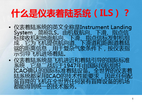
ILS历史
1、AN系统
2、双音频 3、现代的ILS
现代的ILS
现代的ILS是指 符合 ICAO ANEX10 的真正意义上的“仪表着陆系统”
频率 航向频率(VHF):108-112 MHz
下滑频率(UHF):328-336 MHz
辐射 水平极化波,辐射CSB、SBO和Clearance 调制 90+150,90-150,1020
下滑台
由下滑天线阵和下滑设备组成。下滑信标天线辐 射的场型形成下滑面,下滑面与包含跑道中心线 的水平面的夹角为2°~4°之间。下滑信标就是用 来给飞机提供偏离下滑面的垂直引导信号。机载 下滑接收机收到下滑信号后经处理,输出相对于 下滑面的偏离信号,加到HIS上的下滑指示器。若 飞机在下滑面上,下滑指针在中心零位,若飞机 在下滑面的上方或下方,指针就会向下或向上给 驾驶员提供“飞下”或“飞上”的指令。
引导飞机到60米
跑道能见度大于800米,决断高度60米
引导飞机到15米
跑道能见度大于400米,决断高度30米
引导飞机到跑道面
跑道能见度大于200米,台
航向台
由航向天线阵和航向设备组成。航向天线产生的辐 射场在通过跑道中心延长线的垂直面内形成的航 向面(也叫航向道)。航向信标就是用来给提供 飞机偏离航道的横向引导信号。机载航向接收机 收到航向信号后经处理,输出飞机相对于航向道 的偏离信号,加到驾驶仪表板上的水平姿态批示 器(HSI)的航向指针。若飞机在航道对准跑道中 心线,则指针偏离指示为零;若飞机在航向道的 左边或右边,航向指针就向右或向左,给驾驶员 提供“飞右”或“飞左”的指令。
下滑面
跑道
DDM=0 90>150
在航道左方或下滑道上方
仪表等级飞行员理论培训stage2-117-118 SEGMENT 1 REVIEW

Where can you find information on whether a VOT is available at your airport?
• Airport Facility Directory • A/G voice communication panel of the IFR enroute low altitude chart
The altimeter should read within ______ feet for instrument flight.
The altimeter should read within _____ feet for instrument flight
75 Feet
List three types of information displayed by the turn coordinator
Max allowable VOT limits on a VOR check?
Max allowable VOT limits on a VOR check?
• Plus or minus 4 degrees
Dual VOR check limits?
Dual VOR check limits?
List three types of information displayed by the turn coordinator
• •
Rate of Roll Rate of Turn Quality of Turn
What is the max precession for a heading indicator in 15 minutes?
NOTE:
• This is only a partial review of some of the basic information to remember for the instrument rating. It is recommended that you review the other powerpoints, notes, reading, and FAA test questions from the material listed for Segment 1 on your syllabus.
仪表着陆系统培训

02
1
飞行前的准备
2
3
确保飞行当天的天气符合仪表着陆系统的使用标准,如能见度、云高等。
天气条件确认
对飞行器进行全面检查,确保其机械状况良好,包括起落架、襟翼、空速系统等部件。
飞行器检查
对ILS接收机和显示器进行校准,确保系统工作正常。
仪表着陆系统设备的校准
仪表着陆系统的操作流程
根据飞行计划和空中交通管制指令,按照规定的进场航线飞行。
润滑机械部件
对含有机械部件的设备进行润滑,以减少磨损和机械故障。
01
02
03
检查显示器与主机的连接是否正常,以及显示器是否开启。
显示器不亮
检查信号接收器和发射器之间的距离是否符合要求,以及信号接收器是否受到干扰。
信号不稳定
对机械部件进行检查,如有需要可进行润滑或更换。
机械部件故障
常见故障及排除方法
定义
仪表着陆系统能够提供精确的垂直和水平引导,帮助飞行员在低能见度或无法目视着陆的情况下,安全准确地着陆到跑道上。
作用
仪表着陆系统的定义和作用
组成
仪表着陆系统包括地面设备和机载设备。地面设备包括发射装置和进近灯阵列,机载设备包括接收装置、解码器和显示装置。
原理
仪表着陆系统通过地面发射装置向飞机发送无线电信号,机载接收装置接收信号并进行解码,将解码后的信息显示在飞行员面前,从而引导飞行员进行着陆操作。
进场
定位
切入下滑道
着陆
通过ILS接收机接收地面发射的信号,确定飞机在跑道上的位置。
将飞机切入下滑道,调整飞机姿态和速度,准备着陆。
在下滑道上稳定飞机,降落跑道,关闭起落架,完成着陆。
03
故障处理
当ILS设备出现故障时,要迅速采取措施,如关闭故障设备,使用备用设备等。
仪表着陆系统培训课件

仪表着陆系统的信号特征
01
仪表着陆系统是一种利用无线电导航原理,为飞机提供精确的进场着陆引导信息的系统。
02
仪表着陆系统的信号特征包括:方向性、极化性、调制性等。
仪表着陆系统的引导信号解析
仪表着陆系统的引导信号包括:航向引导、下滑引导、距离引导等。
下滑引导是利用仪表着陆系统的下滑信道,向飞行员提供飞机相对于预定下滑线的偏差信息。
04
确保仪表着陆系统正确安装,包括天线、接收机和显示器等部件。
设备安装
按照正确的开关机顺序操作,避免对设备造成损坏。
开关机顺序
在飞行前,检查系统各部件是否正常,确保系统工作正常。
飞行前检查
仪表着陆系统的操作方法
按照制造商的推荐,定期对仪表着陆系统进行维护保养。
仪表着陆系统的维护保养
定期维护
定期清洁设备外壳和内部部件,检查电线和连接是否良好。
仪表着陆系统主要依赖于无线电信号进行工作,这些信号可以被飞行员在飞机上接收并解读。
仪表着陆系统的定义
仪表着陆系统的组成
仪表着陆系统包括三个主要部分:航向信标、下滑信标和指点信标。
下滑信标提供纵向引导,帮助飞行员确定飞机的垂直位置。
航向信标提供横向引导,帮助飞行员确定飞机的位置和方向。
指点信标提供距离信息,帮助飞行员确定他们距离跑道特定点的距离。
与卫星导航系统的比较
卫星导航系统具有全球覆盖和高精度等特点,而仪表着陆系统主要用于机场进近和着陆阶段的导航。
仪表着陆系统与其他导航系统的比较
仪表着陆系统培训课件总结与展望
06
总结本次培训课件的重点内容
了解仪表着陆系统的起源、技术演变和目前的应用情况。
仪表着陆系统的发展历程
仪表飞行课程课件

个气压面之间的垂直距离较大。当飞机在高度表指示5000 英尺时,
此时气压面的实际高度高于在标准温度条件下指示5000 英尺的高
度
,因此飞机的实际高度也就比相对较冷的标准温度条件下的高度高。
当飞机周围温度低于标准大气时,空气密度相对较大,每个气压面
之间的垂直距离较小。当飞机在高度表指示5000 英尺时,此时气
PPT学习交流
4
1.2.2 有关堵塞的问题
皮托管对堵塞特别敏感,特别是由于结冰而 引起的堵塞问题。皮托管的入口是冲压空气进 入全静压系统的地方,轻微的结冰都可以将其 堵塞并影响空速表,这也是为什么大多数飞机 会装备皮托管加热系统的原因。
PPT学习交流
5
1.3 全静压仪表
1.3.1 气压式高度表
气压式高度表是一种膜盒 式气压表,用于测量周围 大气的绝对压力,并以英 尺或米制单位来显示在一 个所调定的压力面之上的 高度。
PPT学习交流
2
1.2 全静压系统
动压或冲压空气压力是通过一个开口的管子直接指向 飞机周围的相对气流而测量得出的。这个管子就叫皮托 管。皮托管连接到使用动压来工作的飞行仪表上,例如 空速表(ASI)。
பைடு நூலகம்PPT学习交流
3
1.2.1 静压
一些仪表依赖周围静止的大气压力来测量飞机的高度以及水平或垂直运动的速度。这种压力叫做 静压,它是通过飞机外部的一个或多个位置的静压孔采样来获得的。在某些飞机上,空气在电加 热皮托静压头一侧的静压孔取样。其它飞机通过位于机身或垂直尾翼上的静压孔获得静压。试飞 证明,静压孔周围的空气不会受到扰动。静压孔通常成对出现,安装在飞机的两侧。这两个位置 可以防止由于飞机的横向运动而导致静压指示错误。静压孔周围的区域可以使用电加热原件以防 止积冰导致空气入口堵塞。在大多数飞机的仪表面板上都能找到三个靠压力工作的基本仪表。它 们分别是气压式高度表、空速表(ASI)和升降速度表(VSI)。这三个仪表接收到的压力都是由 飞机的全静压系统测得的。
仪表等级飞行员理论培训stage2-110-AIRPORTS
• Blast Pad / Stopway Areas
– Yellow chevrons – May not be used for taxi, takeoff, or landing – At military bases, this is called an “Overrun”
Airport Signs
– Includes all on Visual plus: –Threshold Markings –Aiming Point Markings (1000 ft)
Precision Runway Markings
• Precision Instrument Runways
– Includes all on Visual & Non-precision plus:
– Xs or simply blocked off
• Displaced Threshold
– Begin/end normal operations for takeoff and landing rollout, not for landing.
– White arrows leading to displaced threshold
• Hold lines
– keep aircraft clear of runways
– Solid line on taxiway side: Do not cross without clearance!
– Dashed line on runway side: “dash across dashed
– Touchdown Zone Markings
• 500 ft intervals for first 3000 ft or half, whichever is less
仪表等级飞行员理论培训stage1-103 GYROS-COMPASS

A ltimeter (adjustable) B all (slip & skid indicator) C lock A ttitude Indicator R ate of turn indicator D irectional gyro DME at & above FL 240
• Airworthiness Directives (recurring/one-time) • VOR (preceding 30 days) • Inspections (Annual/100 hour if for hire) • Altimeter (preceding 24 calendar months • Transponder (preceding 24 calendar months) • ELT (preceding 12 calendar months) • Static system (preceding 24 calendar mo.)
Heading Indicator
How An HI Works
• Vacuum powered • Gyro spins on vertical plane • Senses rotation about the vertical axis • Free vs. Slaved gyros
– free, must align with magnetic compass – slaved, automatic north-seeking
Turns and G forces
• The pendulous vanes operate asymmetrically under:
– Load – Centrifugal force
仪表飞行课程资料

1.3.4 高度表的改进(编码高度表)
空域系统中如果只有飞行员有飞机高度指示是远远不够的, 地面上的空中交通管制员必须清楚地知道飞机的高度。为了 提供这一信息,通常为飞机配备编码高度计。当 ATC 应答 机调定在C 模式,编码高度表提供一系列识别飞机所在飞行 高度的脉冲信号给应答机(以100 英尺开始递增)。 这一系列脉冲发送到地面雷达并以文字的形式出现在管制员 的屏幕上。通过该应答机可以使地面管制员识别该飞机并确 定飞机所在位置的压力高度。编码高度计中的计算机以 1013.25 百帕为基准测量气压,并将该数值发送给应答机。 当飞行调整气压刻度表到当地高度表调定值,发送给应答机 的数据不会受影响。这样可以保证所有使用方式C 模式的飞 机使用相同的气压标准来发送数据。ATC 设备调整显示的高 度来补偿当地气压差异,从而保证显示目标的正确高度。91 部要求应答机发送的高度误差应在仪表指示高度125 英尺范 围内。
1.3.1.3 机械式误差
飞行员在起飞前检查时应确定高度表的工作状况,将气压刻度盘 调到当地的修正气压值。此时高度表应该指示机场的实际标高。 如果高度表的指示偏离实际标高超过75 英尺,则仪表应该送到指 定的仪表维修站来重新进行校准。不同的外界温度以及不同的气 压也会造成高度表的显示不准确。
1.3.1.4 固有式误差
为了看清楚如何使用修正,注意:机场标高496 英尺机场温度 零下 50 摄氏度IFR 进近图提供以 下数据: 最小程序转弯高度 1800 英尺 最低 FAF 穿越高度1200 英尺 直线最低下降高度800 英尺 盘旋 MDA 1000 英尺 使用 1800 英尺的最低程序转弯高度来举例,来介绍一下如何确定相应的温度修正。通 常,将高度值四舍五入到百位英尺使用最接近高度。图上1800 英尺的程序转弯高度减去机 场标高500 英尺等于1300 英尺。1300 英尺的高度差异在修正航图标高1000 英尺以及1500 英尺之间。报告点温度为-50 摄氏度,修正值在300 英尺以及450 英尺之间。补偿值之间的 差值除以机场之上高度之间的差值得出每英尺的误差值。 本例中,150 英尺除以500 英尺等于0.33 英尺即每1000 英尺之上高度每增加1 英尺 补偿0.33 英尺。前1000 英尺提供300 英尺的修正,每增加0.33 乘以300 英尺,为99 英 尺四舍五入即为100 英尺。300 英尺加上100 英尺等于400 英尺的总的温度修正。对于给 定的情况下,对MSL 之上1800 英尺(等于1300 英尺报告点之上的高度)的标注值进行修 正,则需要增加400 英尺。因此,在指示高度2200 英尺上飞行时,飞机实际上在1800 英 尺高度上飞行。 最小程序转弯高度 标注的 1800 英尺=修正的2200 英尺 最低 FAF 穿越高度 标注的1200 英尺=修正的1500 英尺 直线 MDA 标注的 800 英尺=修正的900 英尺 盘旋 MDA 标注的1000 英尺=修正的1200 英尺
仪表着陆系统培训课件
6
ICAO ANEX10 对ILS的分类和运用条 件
CAT I CAT II CAT III
引导飞机到60米
跑道能见度大于800米,决断高度60米
引导飞机到15米
跑道能见度大于400米,决断高度30米
引导飞机到跑道面
跑道能见度大于200米,无决断高度
7
系统组成
• 航向台 • 下滑台 • 指点标台或DME台
=UcCos(2πfct) + mUcCos[2π(fc+fa)t+ψ]/2 + mUcCos2π[(fc-fa)t-ψ]/2
信号调制
发射机 空间
让发射机分别产生载波信号和后两项的 边带波信号,送到不同的天线上分别辐射,
当分别辐射的载波、上、下边带三者之间满 足一定的关系时,接收机收到它们,等同于 收到一调幅波。这种调制方式,我们称为空
工作原理
航向面
下滑面
跑道
DDM=0 90>150 15 在航道左方或下滑道上方
•基本理论
航
工作原理 向
天 线
调制信号与DDM
飞机上的十字指针
下滑道
16
•基本理论
DDM 航道线
航道宽度: 航道扇区 宽度角即其夹角的度数, 规定不超过6度。
名词术语
航道扇区 下滑道
下滑角
下 滑 道 扇 区
航
34
航向信标台场地及其环境要求
• 航向信标台机房应设置在天线阵排列方向的±30°范围内, 根据当地的地形、道路和电源情况,设置在天线的任意 一侧,距天线阵中心60m~90m,图1中所示,航向信 标台机房及天线高度不应超过机场端净空。
• 在场地保护区内不应有树木、高杆作物,不应修建建筑 物、道路、金属栅栏和架空金属线缆。进入航向信标台 的通信和电源线缆穿越保护区时,应埋入地下。
仪表等级飞行员理论培训stage2-116REGSPART91,NTSB
• Altimeter Settings • Below 18,000’MSL
– Set to a station along route within 100 nm
– ATC periodically advises pilots of current altimeter setting
• At or above 18,000’MSL
– Touchdown zone, markings, lights
– REIL
– Visual Approach Slope Indicator • The approach light system, except that the pilot
may not descend below 100 feet above the touchdown zone elevation using the approach lights as a reference unless the red terminating bars or the red side row bars are also distinctly visible and identifiable.
• Priority by ATC in an emergency – report within 48 hours to manager of particular ATC facility if requested
14 CFR 91.131
• Operations in Class B Airspace • Section (c) Communications and navigation
• Right-of-Way Rules: Except Water Operations
- 1、下载文档前请自行甄别文档内容的完整性,平台不提供额外的编辑、内容补充、找答案等附加服务。
- 2、"仅部分预览"的文档,不可在线预览部分如存在完整性等问题,可反馈申请退款(可完整预览的文档不适用该条件!)。
- 3、如文档侵犯您的权益,请联系客服反馈,我们会尽快为您处理(人工客服工作时间:9:00-18:30)。
Types of Altitude: (cont.)
Density Altitude
– Pressure altitude corrected for nonstandard temperature. – A theoretical value – not a height! – Used solely for determining performance. – Calculated from flight computer or graph.
Airspeed Indicator
Airspeed Indicator
Types of Airspeed:
Indicated Airspeed (IAS)
– Airspeed that is displayed on the instrument – The greater difference between ram air and static air results in higher IAS
1.
Airspeed Indicator
Uses differential pressure from pitot tube and static port(s) Compares ram pressure to static pressure Internal diaphragm vented to pitot tube; sealed instrument case vented to static port(s) What information does it provide?
Types of Altitude: (cont.)
True Altitude
(cont.)
– When altimeter indicates field elevation with correct local altimeter setting, indicated altitude is the same as true altitude.
Types of Altitude:
Indicated Altitude
– Read directly from the altimeter when it is correctly set to the local altimeter setting.
Pressure Altitude
– Altitude displayed on the altimeter when it is set to 29.92 – Regulations require that we set our altimeter to 29.92 when operating above 18,000 feet MSL.
Calibrated Airspeed (CAS)
– Indicated airspeed corrected for installation and instrument errors (static ports and pitot tube) – This error is relatively small in cruise speed ranges and becomes more of a factor at speed extremes – Determined by looking at calibrated tables in POH
Airspeed Indicator Errors
Usually result from blockage of pitot tube or static port Pitot Blockage (incl. Drain Hole) Airspeed indicator will react like altimeter. Why? Pitot Blockage (Drain Hole Open) Airspeed will drop to zero. Why? Static Blockage Airspeed will indicate lower than what it should at higher altitudes and higher than it should at lower altitudes from where blockage occurs. “Reverse Altimeter”
Types of Altitude: (cont.)
Pressure Altitude
(cont.)
– Altitudes at or above 18,000 feet MSL are called flight levels (FL). – Some flight levels are unusable when pressure extremes occur. See FAR/AIM. – Pressure altitude also used for determining performance.
Altimeter Errors
Friction Error – inherent whenever there are moving parts. Mechanical Errors – misalignment or slippage of gears or linkage Hysteresis – results from expanding and contracting of the aneroid wafers. The aneroid wafers do not return to original size. Scale Error – aneroid wafers do not respond uniformly to local pressure differences. To be considered reliable, altimeter should indicate within 75 feet of field elevation.
Types of Altitude: (cont.)
True Altitude
– Actual height above mean sea level. – Indicated altitude = true altitude in flight only under standard conditions with correct altimeter setting. – Nonstandard temperature and pressure causes indicated altitude to differ from true altitude. – Can roughly be determined with flight computer and/or conversion tables. Assumes standard lapse rates.
Airspeed Indicator
Altimeter (Pressure Sensitive)
Indicates height above whatever pressure level is set in Kollsman window Basic component of the pressure altimeter is the aneroid wafer The sealed aneroid wafers expand and contract as atmospheric pressure changes within the sealed instrument case
Absolute Altitude
– The actual height of the airplane above the earth’s surface – Used to determine DH, HAA, HAT, and TCH on published instrument approaches
Altimeter
Altimeter
Altimeter (Pressure Sensitive) (cont.)
The instrument case is vented to static port(s) Altimeter setting dial provides a means of adjusting the altimeter for nonstandard pressure and pressure differences between locations The scale is usually calibrated from 28.00” to 31.00”. Why? Rotating the setting simultaneously rotates the scale and altimeter pointers at a rate of 1” per 1,000 feet in the same direction
Calibration Tables
Types of Airspeed: (cont.)
Equivalent Airspeed (EAS)
– Calibrated airspeed corrected for the compression of air in the pitot tube at particular altitudes and airspeeds – Not a big factor until reaching altitudes above FL200 and airspeeds above 200 knots – Most aircraft that are affected already have EAS compensated for in their TAS indicators and computers