BIFFI电动执行机构
BIFFI执行机构说明icon2000_CHI
2000ICON 2000:新千年的步伐特点半个多世纪以前,Biffi就已经开始制造阀门执行机构,其不断的创新和敢于面对挑战的能力,奠定了她在世界范围内的领导地位。
1992年,Biffi开始了智能型执行机构的研发,自问世以来,受到全世界主要用户的欢迎,从钻井平台到热带雨林,从寒冷的西伯利亚到严酷的沙漠环境,各种场合都有实际应用。
现在,伴随着ICON2000的诞生,我们又向轻松使用、方便维护迈出了一步。
智能执行机构的优点ICON2000系列与传统产品相比,其智能化优点如下:调试简单调试和试运行阶段是执行机构最容易损坏的时期。
一次好的调试通常能解决执行机构使用时遇到的大部分问题。
智能化执行机构核心参数的初始调试可以通过现场操作接口和自带软件实现,不用拆卸一个螺钉螺母即可完成,从而极大缩短了调试时间,并提高可靠性。
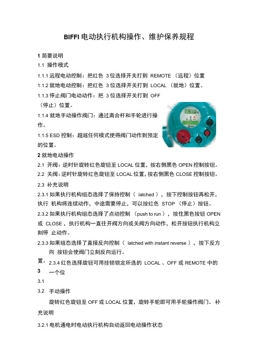
增强型现场操作接口ICON2000执行机构有两个显示窗,用于显示执行机构的动态信息和变量。
上方的窗口可动态显示位置或力矩,下方(两行)显示具体的报警和警告信息等。
在失电和手动操作状态时,位置也能继续显示。
通过现场操作按钮可以对执行机构进行全面的操作,而无须使用其它工具。
用户可以通过设置密码来防止未经授权的操作。
诊断内部电路系统通过不断收集各传感器发来的信息,可连续监视执行机构的状态。
经过综合判断处理可发出各种报警和警告信息,并可用多种语言直接显示,无须繁杂的代码编译。
23更新、更强、更先进…结构更简单可靠,使用更方便结构更简单可靠,使用更方便机械零件数量的减少提高了系统的可靠性并降低了维护费用。
铝合金高强度的外壳,保证了ICON2000能在最恶劣环境中使用。
双重密封将灰尘和潮湿隔离在产品外面。
内部元件的精心选择,提高了整个系统的输出效率(电机直接驱动齿轮),从而降低了操作成本。
提高产品易用性,实现了降低培训成本的目标。
无需编码解码,ICON2000的操作菜单简单明了,并有多种语种选择(意大利语、英语、西班牙语、葡萄牙语、法语、德语)。
BIFFI电动执行机构操作维护规程
置。
3 3.1 3.2 BIFFI 电动执行机构操作、维护保养规程1 简要说明1.1 操作模式1.1.1远程电动控制:把红色3位选择开关打到REMOTE (远程)位置1.1.2就地电动控制:把红色 3 位选择开关打到LOCAL (就地)位置。
1.1.3停止阀门电动动作:把 3 位选择开关打到OFF(停止)位置。
1.1.4 就地手动操作阀门:通过离合杆和手轮进行操作。
1.1.5 ESD 控制:超越任何模式使得阀门动作到预定的位置。
2 就地电动操作2.1 开阀:逆时针旋转红色旋钮至LOCAL 位置,按右侧黑色OPEN 控制按钮。
2.2 关阀:逆时针旋转红色旋钮至LOCAL 位置,按右侧黑色CLOSE 控制按钮。
2.3 补充说明2.3.1如果执行机构组态选择了保持控制(latched ),按下控制按钮再松开,执行机构将连续动作,中途需要停止,可以按红色STOP (停止)按钮。
2.3.2如果执行机构组态选择了点动控制(push to run ),按住黑色按钮OPEN 或CLOSE ,执行机构一直往开阀方向或关阀方向动作,松开按钮执行机构立刻停止动作。
2.3.3如果组态选择了直接反向控制(latched with instant reverse ),按下反方向按钮会使阀门立刻反向运行。
2.3.4红色选择旋钮可用挂锁锁定所选的LOCAL 、OFF 或REMOTE 中的一个位手动操作旋转红色旋钮至OFF 或LOCAL 位置,旋转手轮即可用手轮操作阀门。
补充说明3.2.1电机通电时电动执行机构自动返回电动操作状态3.2.2离合杆可以用挂锁锁定在电动操作位置或手轮操作位置。
3.2.3不允许在手轮或离合杆使用附加外力工具(套杆、 F 扳手、管钳等),防止损坏阀门。
4 执行机构状态指示4.2 LCD 显示信息说明4.2.1 上排LCD 显示阀位开度百分数。
4.2.2下排LCD 显示状态信息:NORMAL(正常)、ESD/ON(ESD 联锁保护)、ALARM (报警)、WARNING (警告)及执行机构的动作情况,包括OPEN (全开)、OPENING (正在开)、CLOSED(关闭)、CLOSING (正在关闭)、STOP (停止)。
biffi说明书
用
在阀门和执行机构的部件上。
进行手动操作,把执行机构垂直安装在阀杆上,完成连接操作,(如果需要在手动操作下进
行)
确信没有过分的外力。
4.3 执行机构装配
14
“ICON2000”电动执行机构
安装及维修手册
Copyright by BIFFI Italia. All rights reserved.
A tyco INTERNATIONAL LTD. COMPANY
执行机构可以在任意位置正常操作。当倒置安装时,应在阀杆盖底部钻 φ5mm 的孔,避免
输送
介质或雨水聚集。
第四部分
备件及装配图 第 66 页
5
“ICON2000”电动执行机构
安装及维修手册
Copyright by BIFFI Italia. All rights reserved.
A tyco INTERNATIONAL LTD. COMPANY
tyco flow control
第一部分:安装说明
第一章
“ICON2000”电动执行机构
安装及维修手册
Copyright by BIFFI Italia. All rights reserved.
A tyco INTERNATIONAL LTD. COMPANY
2.1 型号“A”联轴器
2.1.1 准备轴套
使用弹簧卡钳卸下螺丝;从联轴器上取下衬套,
内部轴向轴承保持在联轴器底部,从轴套上拆下压环,然后拆下轴承
成。
− 检查显示正常。
− 转动手轮直到阀门全部打开。
− 检查读数为 100%,显示阀门完全打开。
BIFFI气液联动球阀培训教材

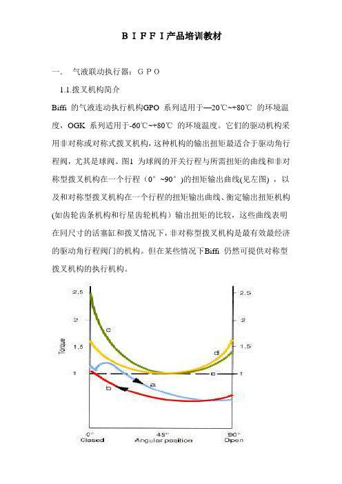
BIFFI产品培训教材一.气液联动执行器:GPO1.1.拨叉机构简介Biffi 的气液连动执行机构GPO 系列适用于-20℃~+80℃的环境温度,OGK 系列适用于-60℃~+80℃的环境温度。
它们的驱动机构采用非对称或对称式拨叉机构,这种机构的输出扭矩最适合于驱动角行程阀,尤其是球阀。
图1 为球阀的开关行程与所需扭矩的曲线和非对称型拨叉机构在一个行程(0°~90°)的扭矩输出曲线(见左图) ,以及和对称型拨叉机构在一个行程的扭矩输出曲线、衡定输出扭矩机构(如齿轮齿条机构和行星齿轮机构)输出扭矩的比较,这些曲线表明在同尺寸的活塞缸和拨叉情况下,非对称型拨叉机构是最有效最经济的驱动角行程阀门的机构。
但在某些情况下Biffi 仍然可提供对称型拨叉机构的执行机构。
拨叉机构的行程为82°~98°可调,它的调整是靠安装在液压缸上的机械制动螺钉(调整关位)和安装在外壳左侧的机械制动螺钉(调整开位)进行调整的,如果执行机构具有二个液压缸,那么两个机械制动螺钉则全部安装在液压缸两侧。
拨叉机构(2)在旋转时是包托在青铜的衬套(3)里,衬套一头安装固定在外壳的法兰里,而另一头则固定在上盖里,拨叉孔上有键槽用于和阀杆相连。
青铜制的滑块在拨叉槽内滑动时,通过滑销(5)接受来自活塞缸的推力滑块销安装在导向块(7)上,活塞杆(11)用螺钉也固定在导向块上。
导向块通过衬套(9)在导向杆(8)上滑动,衬套为烧结青铜镀聚四氟乙烯构成,可将摩擦力降到最低。
气液连动执行机构的活塞缸是用于液压油的,经过搪磨的活塞缸(10)内膛十份平滑,活塞杆(11)通过安装在外壳端法兰上的导向衬套(12)进行滑动。
同样该衬套为青铜表面上镀有聚四氟乙烯,可将摩擦力的影响降到最低,活塞(13)在活塞缸内滑动,为了确保其滑动方向,在活塞上装了导向聚四氟乙烯环(14) ,以保证滑动方向并提高效率。
活塞和活塞杆的密封都是O 形圈,外包聚四氟乙烯密封环,这种材质可适用于许多种恶劣的环境1.2工作原理气液连动执行机构的动力源是高压天然气,天然气在过滤之后通过流量调节阀进入气液连动罐。
biffi电动执行机构投运前调试研究
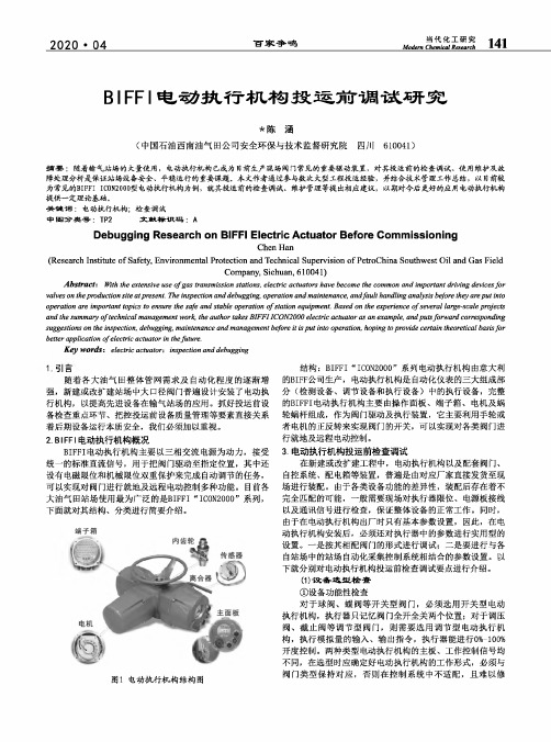
当代化工研究Modem Chemical Research141 2020・04百家争鸣BIFFI电动执行机构投运前调试研究*陈涵(中国石油西南油气田公司安全环保与技术监督研究院四川610041)摘要:随着输气站场的大量使用,电动执行机构已成为目前生产现场阀门常见的重要驱动装置,对其投运前的检查调试、使用维护及故障处理分析是保证站场设备安全、平稳运行的重要课题.本文作者通过参与数次大型工程投运经验,并结合技术管理工作总结,以目前较为常见的BIFFI IC0N2000型电动执行机构为例,就其投运前的检查调试、维护管理等提出相应建议,以期对今后更好的应用电动执行机构提供_定理论基础”关键词:电动执行机构;检查调试中图分类号:TP2文献标识码:ADebugging Research on BIFFI Electric Actuator Before CommissioningChen Han(Research Institute of Safety,Environmental Protection and Technical Supervision of PetroChina Southwest Oil and Gas FieldCompany,Sichuan,610041)Abstracts With the extensive use of g as transmission stations,electric actuators have become the common and important driving devices f ar valves on the p roduction site at p resent.The inspection and debugging,operation and maintenance,and f ault handling analysis before they are p ut into operation are important topics to ensure the safe and stable operation of s tation equipment.Based on the experience of s everal large-scale projects and the summary of t echnical management work,the author takes BIFFI ICON2000electric actuator as an example,and p uts f orward corresponding suggestions on the inspection,debugging,maintenance and management before it is put into operation,hoping to provide certain theoretical basis f or better application of e lectric actuator in the f uture.Key words t electric actuator^inspection and debugging〔引言随着各大油气田整体管网需求及自动化程度的逐渐增强,新建或改扩建站场中大口径阀门普遍设计安装了电动执行机构,以提高先进设备在输气站场的应用。
执行器 国内外知名品牌一览表

国外知名电动执行器品牌
英国罗托克(ROTORK)公司
Rotork诞生于20世纪50年代,在1957年,Rotork工程有限公司在他巴斯的家 ——Widcombe庄园交易。第一台可识别的现代化模板化积于一体的执行器设 计是显而易见的。2006年IQ Pro三代也被研制。Rotork流体系统部成为了全 球最大的流体执行器生产厂商之. Rotork 在全球范围内拥有350个以上的办事处和代表处, Rotork 在工业阀门 执行器,阀门控制系统,阀门齿轮箱及附件的设计和生产上居世界领导地位。
国外知名电动执行器品牌
德国西博思电动执行机构
西博思全球总部位于阿尔特多 夫,主要集中在企业活动:设 计和开发,制造和销售电动执 行器;概念设计和实现的解决 方案在水/污水厂和发电厂; 定制的顾客解决方案的开发;
德国AUMA执行器公司
1964年 企业创立,自动化和现 代化的进程控制系统开始影响工 业 发 展 。 WernerRiester 和 Rudolf Dinse 开始了第一批执行 器的开发。耐用性和可靠性—— 是他们的品质。由于可靠的轻型 设计和小巧外形的运用,并利用 了欧玛专利的齿轮技术,因此可 以实现指导方针。
国外知名电动执行器品牌
德国ABB执行器
ABB是全球领先的电力和自动化 技术, 主要集中于本公司业务是为客户 提供满意的产品和解决方案的仪 器仪表,自动化和工业过程优化 。服务的行业包括石油和天然气 ,电力,化工,制药,纸浆和纸 张,金属和矿物,海洋和涡轮增 压。关键客户的好处包括提高资 产效率和节约能源。
德国EMG
EMG总部位于德国,公司成立于 1946年,距今已有60年的历史,是 德国和欧洲最早的电动执行机构专业 制造商。EMG电动执行器在全球范 围内有着数十年远程诊断、控制阀门 (不管是截止阀、闸阀、旋塞阀、球 阀、蝶阀还是风门)的成功经验。 EMG电动执行器应用于各个不同的 领域,包括电力、水厂、污水处理厂 、石油化工、冶金、造纸、造船、食 品、市政、核电等。
BIFFI气液联动球阀培训教材
BIFFI产品培训教材一.气液联动执行器:GPO1.1.拨叉机构简介Biffi 的气液连动执行机构GPO 系列适用于—20℃~+80℃的环境温度,OGK 系列适用于-60℃~+80℃的环境温度。
它们的驱动机构采用非对称或对称式拨叉机构,这种机构的输出扭矩最适合于驱动角行程阀,尤其是球阀。
图1 为球阀的开关行程与所需扭矩的曲线和非对称型拨叉机构在一个行程(0°~90°)的扭矩输出曲线(见左图) ,以及和对称型拨叉机构在一个行程的扭矩输出曲线、衡定输出扭矩机构(如齿轮齿条机构和行星齿轮机构)输出扭矩的比较,这些曲线表明在同尺寸的活塞缸和拨叉情况下,非对称型拨叉机构是最有效最经济的驱动角行程阀门的机构。
但在某些情况下Biffi 仍然可提供对称型拨叉机构的执行机构。
拨叉机构的行程为82°~98°可调,它的调整是靠安装在液压缸上的机械制动螺钉(调整关位)和安装在外壳左侧的机械制动螺钉(调整开位)进行调整的,如果执行机构具有二个液压缸,那么两个机械制动螺钉则全部安装在液压缸两侧。
拨叉机构(2)在旋转时是包托在青铜的衬套(3)里,衬套一头安装固定在外壳的法兰里,而另一头则固定在上盖里,拨叉孔上有键槽用于和阀杆相连。
青铜制的滑块在拨叉槽内滑动时,通过滑销(5)接受来自活塞缸的推力滑块销安装在导向块(7)上,活塞杆(11)用螺钉也固定在导向块上。
导向块通过衬套(9)在导向杆(8)上滑动,衬套为烧结青铜镀聚四氟乙烯构成,可将摩擦力降到最低.气液连动执行机构的活塞缸是用于液压油的,经过搪磨的活塞缸(10)内膛十份平滑,活塞杆(11)通过安装在外壳端法兰上的导向衬套(12)进行滑动.同样该衬套为青铜表面上镀有聚四氟乙烯,可将摩擦力的影响降到最低,活塞(13)在活塞缸内滑动,为了确保其滑动方向,在活塞上装了导向聚四氟乙烯环(14),以保证滑动方向并提高效率.活塞和活塞杆的密封都是O 形圈,外包聚四氟乙烯密封环,这种材质可适用于许多种恶劣的环境1。
几大品牌的执行器比较分享给大家
第23楼 过客 2008-3-13 【回复】 【回顶部】
罗托克、西博斯的比较好调整,AUMA调节型的门调起来比较麻烦。个人觉得西博斯的质量最好,能长期在非常恶劣的环境下工作,并且故障率很低
第24楼 过客 2008-3-20 【回复】 【回顶部】
ROTORK的执行器不错,虽然也发送故障,但是还好处理,不至于整台更换。
第12楼 过客 2007-12-21 【回复】 【回顶部】
对啊, 国外的电动执行机构可能是太先进的原因吧,洋货的原因吧,我的好多用户都不是很满意的!倒是国内的东西跟好用些!比如上海AUTORK,扬州兰陵的IK3都比较好用的,确实售后也比较好!不担心他们不马上派人!
第13楼 过客 2008-1-1 【回复】 【回顶部】
霍尼韦尔的执行器怎么样?听说可靠性不错。
第14楼 过客 2008-1-5 【回复】 【回顶部】
呵呵,接触过一次奥托克的门,弄得偶焦头烂额的!当时是在一个稍微寒冷点的地方,结果因为齿轮箱润滑油粘滞造成早晚工作不正常,非得中午的时候才好用,没办法最后把齿轮箱的油全部换掉了才好些!平时运行也是故障频现。 西博斯的用着还不错,就是接线设计太不人性化了,查起线来真的不方便。在早晚温差大空气湿度也大的地方使用一定要注意好电缆口密封和安装方向,要不然等着换板子吧:) 罗托克的接触过一些,个人觉得接线设计没什么不方便的,虽然端子比较多,但是好在空间大,只要注意一下应该很少接错位置。这总比一大堆线挤在一个狭小的空间里面让人感觉要好许多。 奥玛的没有接触过,不好发表些感受。 偶还遇到过Limitorque的电动门,运行上可靠性还可以,就是设置起来太麻烦,旋钮转来转去的搞得头都大了。
罗托克是目前电厂关键部位用得最多的执行器,西博斯还是不错,国产品牌天伯/扬修/上仪/常州兰陵/常州辅机这些品质都不错,而且价格合理,我厂扬修/常州兰陵国内品牌用了三年故障率较少,售后服务也较好.但川仪M8000故障太多了,建议不要用,
执行器 国内外知名品牌一览表

上海澳托克
国内知名电动执行器品牌
上仪十一厂
上海澳托克
国内知名电动执行器品牌
扬州西门子
常州施耐德
国内知名电动执行器品牌
扬州恒春
四川川仪
国内知名电动执行器品牌
浙江罗托克
温州瑞基
意大利Biffi 是一家拥有50 多年历史的阀门执 行机构产品领先制造商。 我们是少数几个具 有全球业务部署,并且能够为客户提供标准及 特殊设计的执行杨柳产品的制造商之一,这些 产品包括:电动、气动、液压、气液联动和海 底执行机构产品。所有产品均提供完整的附件 产品,广泛适用于各类应用。 Biffi 的客户化 设计数据库可以在广泛的业务领域内持续帮助 客户优化其阀门自动化需求,这些业务领域包 括: 管线、油气、化工和电力行业。
国外知名电动执行器品牌
德国西博思电动执行机构
德国AUMA执行器公司 1964 年 企业创立,自动化和现 代化的进程控制系统开始影响工 业 发 展 。 WernerRiester 和 Rudolf Dinse 开始了第一批执行 器的开发。耐用性和可靠性—— 是他们的品质。由于可靠的轻型 设计和小巧外形的运用,并利用 了欧玛专利的齿轮技术,因此可 以实现指导方针。
德国EMG
EMG总部位于德国,公司成立于 1946年,距今已有60年的历史,是 德国和欧洲最早的电动执行机构专业 制造商。EMG电动执行器在全球范 围内有着数十年远程诊断、控制阀门 (不管是截止阀、闸阀、旋塞阀、球 阀、蝶阀还是风门)的成功经验。 EMG电动执行器应用于各个不同的 领域,包括电力、水厂、污水处理厂 、石油化工、冶金、造纸、造船、食 品、市政、核电等。
国外知名电动执行器品牌
法国伯纳德
意大利BIFFI(泰科)
Biffi ICON 2000电动执行器-E
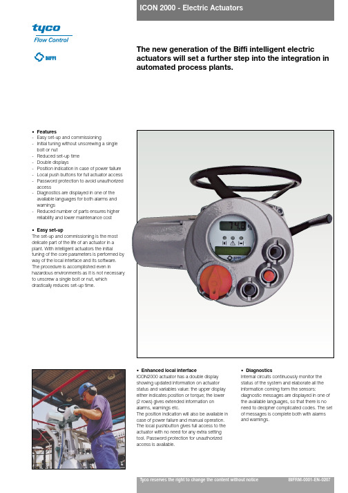
Tyco reserves the right to change the content without noticeBIFRM-0001-EN-0207The new generation of the Biffi intelligent electric actuators will set a further step into the integration in automated process plants.•Features-Easy set-up and commissioning-Initial tuning without unscrewing a single bolt or nut-Reduced set-up time -Double displays-Position indication in case of power failure -Local push buttons for full actuator access -Password protection to avoid unauthorized access-Diagnostics are displayed in one of the available languages for both alarms and warnings-Reduced number of parts ensures higher reliability and lower maintenance cost •Easy set-upThe set-up and commissioning is the most delicate part of the life of an actuator in a plant. With intelligent actuators the initialtuning of the core parameters is performed by way of the local interface and its software.The procedure is accomplished even inhazardous environments as it is not necessary to unscrew a single bolt or nut, whichdrastically reduces set-up time.•DiagnosticsInternal circuits continuously monitor the status of the system and elaborate all the information coming form the sensors:diagnostic messages are displayed in one of the available languages, so that there is no need to decipher complicated codes. The set of messages is complete both with alarms and warnings.•Enhanced local interfaceICON2000 actuator has a double display showing updated information on actuator status and variables value: the upper display either indicates position or torque; the lower (2 rows) gives extended information on alarms, warnings etc.The position indication will also be available in case of power failure and manual operation.The local pushbutton gives full access to the actuator with no need for any extra setting tool. Password protection for unauthorized access is available.The reduced number of mechanical parts ensures higher reliability and lowermaintenance costs.The aluminium alloy highly resistant housing and covers, together with a lower number of joints, have increased Icon capacity to stand up to the most aggressive environments.A double-sealed enclosure assures protection from dust and humidity. The choice of internal components has increased the overall system efficiency (the motor is directly engaged to the gears) lowering the operational cost.Reduction of training costs is also one of the goals we have achieved throughthe user-friendliness of the system.No more codes to decipher: Icon menu is clear and easy, with the possibility to choose one of the available languages ( Italian, English, Spanish, Portuguese, French and German).All internal sensors are contactless.•Torque sensorThe direct measure of the motor speed, reports torque with high precision and a resolutionof 1% of the nominal torque.•Position sensorControlled by a dedicated microprocessor with low power consumption, it is based onHall-effect incremental encoder with a resolution of 10°of output shaft rotation.Rotations in both senses are recognized and counted.If manually operated during power failure, the position is updated, stored and displayed locally.•Electronic card: the latest technologyThe card is controlled by high performance 16 bit microchip, Hitachi, with a flash memory of 128Kb.This allows high flexibility and the possibility to be re-programmed in case of need.All the internal wiring has been considerably reduced.The modular design of the electronic cards allows high flexibility for a great variety ofcombinations.Double sealed terminal box for high protection.Wide enclosure to facilitate wiring connection Heavy-duty simplifiedgearing for higher efficiencyHigh precision internalsensors. Lowconsumption positionencoder specificallydesigned for electricactuatorsUser friendly interface:actuating your valve hasnever been so easyEasy connection for quick motor removal Recessed buttonsto prevent them from being damagedTyco reserves the right to change the content without notice page 2page 3The base version is an intelligent actuator with hardwired (i.e. point to point) connection.•Automatic phase correctionThe valve will be protected as the system automatically recognizes and corrects phases preventing any unforeseen error in rotation sense.•Phase failure correctionIn case of loss of one of the phases, this feature prevents the motor from overheating. Theminimum time to set the alarm on is 100 ms, in order to prevent the system from being influenced by casualoscillations. In case of loss of one phase during motor running, the actuator will reachthe end-of-travel position before setting the alarm condition and de-energizing the actuator.•Motor thermostatIf during operation the temperature of the motor overrides the security limits, a thermostat will set the alarm condition and the command signal will be inhibited.•Jammed valve protectionIf, after a command (close/open), the valve position does not change within a pre-set time, an alarm condition is set and the command signal will be inhibited. The pre-set time can be any time within the interval 2 to 100 seconds.•Anti-hammer protectionThis feature will protect both the motor and the valve. If a torque limit is reached it will prevent the valve from moving in the same direction which has caused the torque limit.•Instantaneous reversal protectionWhen the actuator is operating in one direction and an immediate command for a reversedirection is set, unpredicted current surges arise with possible damages to the motor. To prevent such problems, a delay between the opposite commands can be programmed from 500 ms to 5 seconds.•WarningsWarning signals become active when the operating conditions are close to a critical alarm level.Warning is displayed but operation is not interrupted.•Remote output contactsFour voltage-free latching contacts are available from the actuator electronic cards for remote indication. Each one of them can be configured as Normally Open or Normally Closed for one of the following conditions:- Fully open - Motor over temperature - Fully closed - Torque alarm - Intermediate position - Torque alarm in opening - Position = XX %- Torque alarm in closing - Position = XX %- Jammed valve alarm - Actuator opening - Jammed valve in opening - Actuator closing - Jammed valve in closing - Motor running - Mid-travel alarm - Blinker - Warning - Local selected - Low battery - Remote selected - Local stop active - ESD active- Manual operation•Emergency shutdown (ESD)When an ESD signal is received (i.e. in an emergency situation), the actuator performs the ESD programmed action. It can be configured to override any of the following conditions:- Selector in LOCAL- Selector in OFF- Motor temperature alarm- Local STOP pushbutton- Torque alarm- 2 speed timerand it can be programmed to one of the following:- Stay put- Move to open position- Move to close position- Move to pre-set position•Monitor relayWhen the actuator is not available for remote control, an alarm condition is set. The contact type is a change-over voltage-free. The monitor relay is normally energized and will be de-energized on:- Loss of power- Speed sensor- Electrical contactor failure- Configuration error- Internal temperature alarm- Hardware error- Position sensor- Mid-travel alarmThe following conditions can be individually configured to switch over the monitor relay:- Loss of one phase- Jammed valve- Local stop activated- Manual operation- Local selector switch in LOCAL/OFF- ESD signal- Motor temperature alarm- Low battery- Torque alarm•Contactor failureAs one of the vital parts of the actuators, contactors are continuously monitored. If a malfunction is detected an alarm is set and the command is inhibited.•Maximum torque alarmDuring torque operation, if the current torque exceeds the relevant set value, the actuator command is inhibited and an alarm condition is set.•Opto-coupled remote controlsActuator may be remotely controlled by 4, 3 or 2 wires, depending on the connection made on terminal board. Various options are available: latched, momentary, etc...•Torque alarm by-passDuring opening command, starting from open/closed position it is possible to set an interval from 0% to 20% of the total stroke where torque alarm is ignored. This will allow the actuator to win the Break-to-open torque.•High/Low electronic temperatureThrough a semiconductor-based temperature sensor, the temperature in the electronic card is detected and an alarm condition is set if the lowest/highest limits are reached.The local interface has been designed to be easily operated andto have a complete and clear set of information available.It is composed of- a padlockable three-position selector for LOCAL/OFF/REMOTE operation selection- Three pushbuttons for both local OPEN/CLOSE/STOP controls and menu navigationAll buttons are recessed for protection from accidents or misuse.Through the local interface the field operator can enter a basic configuration menuwhich allows to set the following parameters:Base parameters- End of travel position in opening/closing- Opening/closing torque values- Position/torque display- Opening/closing by torque/position- Output contacts- ESD feature- Remote/Local control featureExtended parameters- Timer parameters- Position servo-amplifier parameters- Fieldbus interface parameters- PID parameters- ….The configuration menu is password protected.Three LEDs with settable different colors to indicate valve opening/closing, alarms, warnings, mid-travel and end-of-the-stroke positions.•Predictive maintenanceSome of the most vital parts of the actuator are monitored:- contactor cycles count- torque trend- alarms data log•Timer Function Module (TMR)It allows for partial or complete timer controlled valve stroke.Through the local/remote interface the following can be set:- if it has to be active during opening or closing operation- ON time, from 1 to 200 sec max, with steps of 1 sec.- OFF time, from 1 to 200 max, with steps of 1 sec.- percentage of position when timer starts on opening- percentage of position when timer starts on closing•Data logICON2000 is complete with an exhaustive data log system which will allow for storage of main events which areoccurring during actuator operation. The data monitored are:Alarms:❑Last 5 alarms and date❑Last 5 warnings and dateTorque profiles:❑Breakout reference torque in opening❑Peak running reference torque in opening❑Ending reference torque in opening❑Breakout torque in opening❑Peak running torque in opening❑Ending torque in opening❑Breakout reference torque in closing❑Peak running reference torque in closing❑Ending reference torque in closing❑Breakout torque in closing❑Peak running torque in closing❑Ending torque in closing❑Data of the last “set torque reference”❑Date of last torque profile in opening❑Date of last torque profile in closingOperations:•Opening time of the last stroke•Closing time of last stroke•Total contactor operations•Motor run time•Time out without electrical power•Utilization rate•Recent contactor operations•Recent motor run time•Recent time without electrical power•Recent utilization rateMaintenance data:•Last maintenance date•Next maintenance date•Date of the last “clear recent data log”•Start-up date•Name plateThe basic information of the actuator is electronically stored in a non-volatile memory:•Serial number•Actuator size•Nominal torque•Actuator speed•Power supply•Motor rating•Motor duty•Motor poles•Motor type•Motor current•Test date•Wiring diagram•Enclosure•Certificate•Lubricant•HW version•SW version•Valve dataTo identify the valve and its function in the process, the valve manufacturer/end user can enter the following data:•valve tag name•valve serial numberFor such information 28 characters are available.•Customizable torque profilesIn some applications you need to set different torque profiles for operating the valve.For this reason we have introduced a 3-point torque profile.page 7The following is a description of our ICON2000 standard features/options and working conditions. For whatever you may require which is not listed below, please contact Biffi Sales offices.Voltage ratingsThe actuator can accept the following voltage supplies:Three phase:-50 Hz-60 Hz230, 240, 380, 400, 415, 440, 460, 480, 500, 690 V 208, 280, 380, 460, 480, 575 VSingle phase-110, 115, 220, 240 V at 50, 60 Hz Direct Current-24, 48, 110, 240 VTolerance on fluctuations-Voltage: ±10% continuous +10% -15% intermittent -Frequency: ±2%Working temperature-The standard range is -30°C to +85°C -Extended ranges -40°C to +70°C-Special low range temperature version -55°C to +70°C Storage temperature -From -55°C to +85°CSafety Compliance•Electromagnetic compatibility directive (EMC)ICON2000 actuators conform to the requirements of EMC Directive 89/336/EEC and further amendments.•Low voltage directive (LV)ICON2000 actuators conform with Low Voltage Directive 73/23/EEC and further amendments by the application of EN60204-1 1993.•Machinery directiveICON2000 actuators comply with the provision of Machinery Directive 98/37/EEC.Environmental protections •Only waterproofIP 68 according to IEC 529 and CEI EN60529 (15 m dept/90 hours), or alternatively NEMA 4,NEMA 4X and NEMA 6 according to NEMA ICS6•Standard explosionproof degreeEEx-d IIB T4 according to EN50014, EN50018 and EN50281-1-1 Class I, div.1 group C and D – Class II, III, div.1 groups E, F and G.IP 68 according to IEC 529 and CEI EN60529 (15 m dept/90 hours), or alternatively NEMA 4,NEMA 4X and NEMA 6 according to NEMA ICS6•Option 1EEx-d IIC T4 according to EN50014, EN50018 and EN50281-1-1 Class I, div.1 group B, C and D – Class II, III, div.1 groups E, F and G.IP 68 according to IEC 529 and CEI EN60529 (15 m dept/90 hours), or alternatively NEMA 4,NEMA 4X and NEMA 6 according to NEMA ICS6•Option 2EEx-de IIB T4 according to EN50014, EN50019 and EN50281-1-1 Working temperature range:-55°to + 65°C IP 68 according to IEC 529 and CEI EN60529 (15 m dept/90 hours), or alternatively NEMA 4,NEMA 4X and NEMA 6 according to NEMA ICS6Test Summary•Life testStandard ICON2000 life test is based on AWWA 540-93 for a minimum of 10,000 cycles.•Vibration testICON2000 are certified as per IEC 60068-2-6- Appendix B (plant induced): frequencies from 1 to 500 Hz (in 3 axes) with 2.0g peak acceleration. Sweep cycles in each axis: 10.•Seismic testICON2000 are tested in accordance with IEC 60068-2-57. Frequencies from 1 to 35 Hz (in 3 axes) with max 2.0g peak acceleration. Verification of structural integrity at 5g. Endurance of oscillogram: 30 seconds.•Environmental testICON2000 are tested according to the following standards: IEC 68-2-1 (cold) up to –55°C, IEC 68-2-2 (dry heat) up to +85°C, IEC 68-2-3 (damp heat) up to +40°C with 93% relative humidity.•Salt spray testICON2000 external coating is tested for resistance to salt spray for 1,500 hours according toASTM B117/IEC 68-2-11.•Noise testICON2000 are tested according to EN21680. Noise level is less than 65 dB (grade A) at 1m distance.MotorsBase-version ICON2000 actuators are equipped with three-phase asynchronous, squirrel cage, induction-type low-inertia balanced motors. For single phase or direct current supply, a special interface allows the use of conventional asynchronous motors. The open frame is protected by an Explosionproof / Waterproof cover fixed on the actuator housing. Internal protection by a temperature sensor, inserted in the motor windings.The motor flange is directly coupled to the actuator housing with internal flying leads wired to an intermediate terminal board.Cinematic reduction chain and lubricationMotor power is transmitted to the output hollow shaft directly via a high torque capability and high efficiency worm shaft/worm wheel reduction without any interposition of spur or helical gears. Output hollow shaft is with teeth termination in order to transmit only a torque to the stem nut.Lubrication is through an oil bath with two points for filling and draining.Manual overrideAll actuators are provided with a hand-wheel (without external spokes) for manual operation. The de-clutching mechanism is designed so that motor operation always has priority over manual operation. Whenever the motor is started, the hand mechanism will automatically disengage without engaging the operator. The de-clutch lever is padlockable in two positions (only electrical or only manual) to prevent undesired operation.Terminal blockTerminal block is located in a double sealed enclosure.The terminal block is provided with the following terminations and accessories:- 3 terminals for power supply-46 terminals for controls- 2 for DC external supply- 2 for low voltage (max 230V) external supply- 1 external earth- 1 external neutralCable entriesThree cable entries are supplied as standard.One extra entry is optionally available.The standard thread is NPT and diameter is:-one with 1 1/2”-two with 1”-one with 3/4” (optional)ISO Rc 7/1, ISO metric BS3643 and DIN 40430/PG and different diameters are available as optional.page 9A large variety of optional modules can be added to the base version. If the option you are looking for is not listed below, please contact Biffi.Extended temperature ranges-40/+70 °C by use of extended range components-55/+70 °C by use of a heating source for internal electronic components, powered by external supply.Additional Output Contacts (AOC)This module provides 7 additional SPST output contacts to be configured “make or break ”.Position Analogue Retransmission Module (APTM)This card gives a 4-20 mA galvanically insulated module for position or torque retransmission, plus three additional SPST output contacts to be configured “make or break ”, and 2 interlock inputs.Torque/position Analog Retransmission Module (ATTM)Same as APTM but with two 4-20 mA galvanically insulated modules for position and torqueretransmission, plus three additional SPST output contacts to be configured “make or break ”, and 2 interlock inputs.PID moduleThis module is useful when a closed loop control of a process variable is requested.It can receive an analogue signal from a transducer and drive the actuator to maintain the desired set-point value of the parameter (temperature, pressure, flow).Solid state power switch over temperature (only for heavy modulation duty version)It detects power card maximum temperature condition and sets the relevant alarm.Fieldbus interfacesICON2000 modular design is easily upgraded from base-to-base to bus versions. All that is needed is to add the relevant plug-in card.ICON2000 flexible interface allows connection to the major field bus available on the market:Foundation Fieldbus Profibus DP LonWorks DeviceNet ModbusPlease ask our Sales people for specific requirements.Position Servoamplifier Module (PSM)The module is necessary for actuators in modulating and inching duty. It drives the motor through pulses at constant frequency and duration proportional to the position error,following an externally set analogical point signal.The basic features are:Input: 4-20 mA or 0-20 mA with galvanic insulationOutput: 4-20 mA with galvanic insulation for position or torque re-transmission.Three additional SPST output contacts to be configured “make or break ”.2 interlock inputs.Anti-condensate heaterThe internal modules provide enough power to grant anti-condensation protection for general applications. But when the environment air humidity reaches critical levels, an additional heater (10 Watt - 1500 Ohm, with external power supply) may be supplied on request.BatteryAuxiliary batteries can be provided in an intrinsically safe enclosure.With auxiliary batteries it will be possible to remotely transmit position also in case of power failure.Hand-wheel with reduction gearingSide hand-wheel with additional reduction, with engagement lever.The reduction on the manual operation reduces the torque at the hand-wheel. This provides less “rim-pull ” force for the operator.The following ratios are applicable:model ratio 03010:104013:105017:1Special couplingsTo be able to cope with different applications and working condition, two special couplings are available:•The linear coupling was designed for the motorization of valves with stem linear movement and no anti-rotational devices on the stem (e.g. application on modulating globe valves). This type of coupling converts multi-turn actuator rotational motion into linear motion: in this way the motorization is extremely simple and compact.•Spring-compensated coupling ASC type. The spring coupling block has its best application on actuators for wedge and globe valves working at high temperatures. The trim of valves working at temperatures higher than 450°C and subjected to large temperature changes undergoes expansions and contractions that are very dangerous to the valve and to the actuator thrust coupling. If, on the other hand, low temperatures are causing contractions, valve unseating could occur. The spring-compensated coupling is designed to cope with both high and low temperatures: the spring cups allow the stem nut to move axially. The same coupling can also be used in case of high speeds, as the springs reduce the over-strokes effects by absorbing thekinetic energy.MassModel A a1a2B b1b2ØC F H h1h2h3Kg ICON-03064839924962431331130048617118226378ICON-04072345526873136037140055819619128494ICON-050779508271860430430500693223218336118MassModel A a1a2B b1b2ØC H h1h2h3Kg page 10*The information herein contained is reserved property of Biffi and is subject to being modified without notice.Standard cable entries:a = 1” NPT b = 1 1/2” NPTISO 5210 “F ” sizeStandard cable entries:a = 1” NPT b = 1 1/2” NPTICON-010485325137562273289300F1032413813821032ICON-020597347140572283289500F1437416116124045ICON-030699399161624313311600F1442717118226870ICON-040815455170731360371720F1647819619128486ICON-050938508180860430430860F25549223218336110ØCAa1a2A 62 62a1a2b aB Ah 1h 1h 2h 2h 3h 3HHBBb 2b 2b 1b 1Nom. Torque(2)Min. Torque Max. Torque(3)RPM RPM Motor Motor Power Motor Power R Model(1)(100%) (Nm)(Nm)(Nm)(50 Hz)(60 Hz)Type(KW) at 50 Hz(KW) at 60 HzICON-010/30-**3012451214SM000.0300.03640:01 ICON-010/30-**3012451822SM010.0460.05540:01 ICON-010/30-**3012452429SM100.0710.08520:01 ICON-010/30-**3012453643SM110.1060.12720:01 ICON-010/30-**3012454858SM040.1420.17020:01 ICON-010/30-**3012457286SM050.2130.25620:01 ICON-010/30-**301245144173SM060.4260.51120:01 ICON-010/90-**90361351214SM100.0710.08540:01 ICON-010/90-**90361351822SM110.1060.12740:01 ICON-010/90-**90361352429SM120.1220.14620:01 ICON-010/90-**90361353643SM130.1840.22120:01 ICON-010/90-**90361354858SM140.2860.34320:01 ICON-010/90-**90361357286SM150.3670.44020:01 ICON-010/90-**9036135144173SM160.7350.88220:01 ICON-020/180-**180722701214SM120.1220.14640:01 ICON-020/180-**180722701822SM130.1840.22140:01 ICON-020/180-**180722702429SM140.2860.34340:01 ICON-020/180-**180722703643SM150.3670.44040:01 ICON-020/180-**180722704858SM210.5260.63120:01 ICON-020/180-**180722707286SM220.7890.94720:01 ICON-020/180-**18072270144173SM23 1.470 1.76420:01 ICON-030/360-**3601445401214SM140.2860.34380:01 ICON-030/360-**3601445401822SM150.3670.44080:01 ICON-030/360-**3601445402429SM210.5260.63140:01 ICON-030/360-**3601445403643SM220.7890.94740:01 ICON-030/360-**3601445404858SM30 1.123 1.34820:01 ICON-030/360-**3601445407286SM23 1.470 1.76440:01 ICON-030/360-**360144540144173SM31 3.368 4.04220:01 ICON-040/720-**72028810801214SM210.5260.63180:01 ICON-040/720-**72028810801822SM220.7890.94780:01 ICON-040/720-**72028810802429SM30 1.123 1.34840:01 ICON-040/720-**72028810803643SM40 1.684 2.02140:01 ICON-040/720-**72028810804858SM41 1.939 2.32720:01 ICON-040/720-**72028810807286SM31 3.368 4.04240:01 ICON-040/720-**7202881080144173SM42 5.818 6.98220:01 ICON-050/1440-**144057621601214SM30 1.123 1.34880:01 ICON-050/1440-**144057621601822SM40 1.684 2.02180:01 ICON-050/1440-**144057621602429SM41 1.939 2.32740:01 ICON-050/1440-**144057621603643SM31 3.368 4.04280:01 ICON-050/1440-**144057621604858SM50 3.879 4.65520:01 ICON-050/1440-**144057621607286SM42 5.818 6.98240:01 ICON-050/1440-**14405762160144173SM5111.63613.96320:011.The ** are to be replaced by RPM value at selected frequency (50 or 60 Hz)2.Nominal output torque settable from 40% (minimum torque) to 100% of indicated value3.Theoretic max output torque. The actual max output torque is a function of speed and motorpower supply and may vary from 1.4 to 2 times nominal output torque4. The above performances are referred to ON/OFF S2-15’ or INCHING S4-25%-60 starts/hourduties (IEC34-1)Nom. Torque(2)Min. Torque Max. Torque(3)RPM RPM Motor Motor Power Motor Power R Model(1)(100%) (Nm)(Nm)(Nm)(50 Hz)(60 Hz)Type(KW) at 50 Hz(KW) at 60 HzICON-010/30-**3012451214TM000.0300.03640:01 ICON-010/30-**3012451822TM010.0460.05540:01 ICON-010/30-**3012452429TM100.0710.08520:01 ICON-010/30-**3012453643TM110.1060.12720:01 ICON-010/30-**3012454858TM040.1420.17020:01 ICON-010/30-**3012457286TM050.2130.25620:01 ICON-010/30-**301245144173TM060.4260.51120:01 ICON-010/90-**90361351214TM100.0710.08540:01 ICON-010/90-**90361351822TM110.1060.12740:01 ICON-010/90-**90361352429TM120.1220.14620:01 ICON-010/90-**90361353643TM130.1840.22120:01 ICON-010/90-**90361354858TM140.2860.34320:01 ICON-010/90-**90361357286TM150.3670.44020:01 ICON-010/90-**9036135144173TM160.7350.88220:01 ICON-020/180-**180722701214TM120.1220.14640:01 ICON-020/180-**180722701822TM130.1840.22140:01 ICON-020/180-**180722702429TM140.2860.34340:01 ICON-020/180-**180722703643TM150.3670.44040:01 ICON-020/180-**180722704858TM210.5260.63120:01 ICON-020/180-**180722707286TM220.7890.94720:01 ICON-020/180-**18072270144173TM23 1.470 1.76420:01 ICON-030/360-**3601445402429TM210.5260.63140:01 ICON-030/360-**3601445403643TM220.7890.94740:01 ICON-030/360-**3601445404858TM30 1.123 1.34820:01 ICON-030/360-**3601445407286TM23 1.470 1.76440:01 ICON-030/360-**360144540144173TM31 3.368 4.04220:01 ICON-040/720-**72028810802429TM30 1.123 1.34840:01 ICON-040/720-**72028810803643TM40 1.684 2.02140:01 ICON-040/720-**72028810807286TM31 3.368 4.04240:011.The ** are to be replaced by RPM value at selected frequency (50 or 60 Hz)2.Nominal output torque settable from 40% (minimum torque) to 100% of indicated value3.Theoretic max output torque. The actual max output torque is a function of speed and motorpower supply and may vary from 1.4 to 2 times nominal output torque4.The above performances are referred to ON/OFF S2-30’ or MODULATING S4-25%-600starts/hour duties (IEC34-1)。
Biffi_液动执行机构

GIG高压气动执行机构
• 直动式高压气动执行机构
GIG高压气动执行机构
• 直动式高压气动执行机构
气液联动执行机构简介
GPO气液联动执行机构
气液联动执行机构:
• • • • • 输送管线的安全保护装置 采用管线内天然气压力为动力源 检测阀门下游侧压力变化,压力降,压力低等 驱动阀门关闭 现场手动操作
GPO气液联动执行机构
用户最关心什么? • 球阀长期不动,事故时必须能顺利关闭,不能卡死
• • • • 阀门的粘连问题 执行机构的粘连问题 输出扭矩的安全系数 抗震动
ICON2000电动执行机构
在结构上
• 防护等级:IP68,15米水深,60个小时 • 防爆等级:EExd II B T4 • 温度范围:-30 到+85度
ICON2000电动执行机构
在结构上
ICON2000电动执行机构
在结构上
• • • • • 对电机结构设计的改进使安装和拆卸非常容易. 低功耗电机 H 级绝缘等级 使用电压范围广 开关型和调节型
取得许可认证的主要用户:
Aramco British Gas Gaz de France Kuwait National Petroleum Co. (K.S.C.) Kuwait Oil Co. (K.S.C.) Saline Water Conversion Corp. (SWCC) Shell Abu Dhabi Water & Electricity Dept. Petrobras Enagas Kala Ltd.
EHA一体化电液控制系统
• • • • • • 结构简单精巧 能耗低 自动化程度高 智能化间歇工作低功耗电机 可与电子式爆管检测装置配套 可与太阳能板配套使用
BIFFI icon2000电动阀门操作手册
执行机构在出厂时完好,并各自附有测试报告。为了在执行机构安装到位前保持其出厂性能, 在贮运期必须进行适当处理。
BIFFI 执行机构防护等级是 IP68。但该防护等级必须在执行机构现场正确安装/连接及正确存 储的条件下,才能保证。
用于堵住电缆进线孔的标准塑料帽不是全天候防护的,它们只是用于防止运输过程中进入异 物。
设备安全-基本概念、设计通用原则。第一部分 - 基础术语、方法论; 设备安全-基本概念、设计通用原则。技术原理及规格; 工业机械的电气设备。第一部分:通用要求 机械指导 低压指导 电磁兼容指导 电气效能指导
2. 约定条件
我们对交付用户每一件产品,在正确安装、适当操作和维护的情况下,提供材料和制造工艺质 量方面的品质保证,并且符合当前的产品规格。产品保质期为一年,从第一用户安装之日算起,或
按拆下时的相反顺序装配内部零件,紧固压环,保证轴套仍旋转自由,然后安装到减速器上。如后 描述。
2.2 型号 B1 和 B2 联轴器
2.2.1 准备衬套
用合适的卡钳拆下卡环 拆下推力环 现在可加工适合连接要求的轴套孔。
2.2.2 重装内部零件 用合适的溶剂清洗拆下零件,然后用压缩空气干燥,确认没有金属屑或异物,然后将所有部件
2.1 型号“A”联轴器
2.1.1 准备轴套
使用弹簧卡钳卸下螺丝;从联轴器上取下衬套,
内部轴向轴承保持在联轴器底部,从轴套上拆下压环,然后拆下轴承
Copyright by BIFFI Italia. All rights reserved. A tyco INTERNATIONAL LTD. COMPANY
tyco flow control
第一部分:安装说明
第一章 通用安全说明
BIFFI电动执行器拒动原因分析
• 21•智能电动执行器作为天然气生产场站管道阀门的驱动装置,其控制系统较为复杂,涉及到机械、电力电子技术,通讯技术等技术领域。
故障处理需要通过各种检测方式才能实现。
如果这些问题不及时处理,特别在高含硫原料气井站发生泄漏、爆管等情况,在现场难以实施有效的抢险措施,存在相对较大的安全隐患。
在天然气生产场站使用的电动执行机构主要用在干线球阀、排污阀、收发筒球阀,场站内执行机构多随建站设置,部分阀门及电动执行机构投入运行多年,老化严重,故障多,管理难度大,天然气生产系统中对电动执行机构进行有效维护的方式就是每年定期两次维护保养。
近年来,天然气生产场站管道不断引入智能电动执行器作为阀门的驱动装置,其控制系统较为复杂,涉及到机械、电力管道工艺流程倒换,在属地监督下一一对阀门进行清洁润滑、加注清洗液,对电动执行器手动、就地电动、远程功能测试。
当操作上位机远程测试G8电动阀,电动执行器拒动,无法驱动阀门旋转,执行器屏幕上LED报警指示灯无报警信息。
2 原因分析2.1 输入回路故障G8电动执行器就地电动能开/关阀,说明主板内部逻辑运算控制功能正常。
在远程控制模式下执行器接到上位机运行命令,如主板输入信号检测回路、计算机组态、控制电缆及接线端子接触不良,都有可能造成执行器拒动。
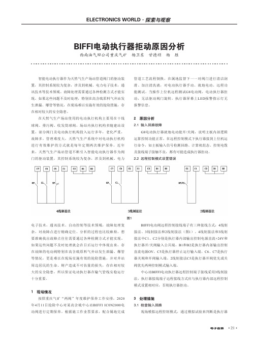
2.2 远程控制模式设置错误BIFFI电动执行器拒动原因分析西南油气田公司重庆气矿 杨卫东 甘德顺 杨 胜图1电子技术,通讯技术、自动控制等技术领域,故障处理复杂,对故障点进行精确定位、分析的过程也比较麻烦,想要准确找出故障点往往需要通过各种检测方式才能实现。
如果这些问题不及时处理就会在日后运行中体现出来,存在故障的电动阀特别在高含硫原料气井站发生泄漏、爆管等情况,更是难以在现场实施有效的抢险措施,并对井站周边居民的生命、财产造成不可估量的损失,存在相对较大的安全隐患,所以保证电动执行器在输气管线安稳运行十分重要。
1 现场情况按照重庆气矿“两阀”年度维护保养工作安排,2020年4月11日抢险中心对某高含硫中心站BIFFI IC0N2000电动阀进行定期保养。
BIFFI破管检测系统功能介绍

BIFFI ELBS-10破管检测系统技术文件ELBS-10型破管检测系统持续临测管道的压力并在事故时,给执行机构发送信号,驱动阀门至故障安全位置。
其工作所需的电源是6V锂电池组,可使ELBS-10连续工作至少一年以上。
ELBS-10配有功能强大的就地人机操作接口,该接口包括一个两行/16字符LCD显示板和3个按钮(上翻键、下翻键和回车键),可进行该装置的参数设置和显示,另外还可提供一个RS232的串行接口。
一、工作原理ELBS-10采用压力变送器对管线压力进行周期性的数据采集,并将取样值记忆到动态滚动寄存器,该寄存器的形式为先进先出式(FIFO),可以存储256个数据,取样速率可在1到99秒内设定。
压力的变化和压降速率与存储在内存中的设定参数不断进行比较,一个事件定义为当压力或压降速率超出用户的设定值并持续一定时间(可设定)。
当事件发生时后,在FIFO寄存器中的压力值以及相关事件发生之前的88个数据,和之后的168个数据,被转存到数据存储器中。
然后每4个数据取1个到事件数据存贮器中,这样每个事件一共记录64个数据(事件前22个及事件后42个)。
事件数据存贮器共能存贮1000个事件。
ELBS-10将以下种类的事件传送到事件数据存贮器中:事件1----压力降低量超过了设定值(现场可设定)事件2----压力降低至最小值。
(现场可设定)事件3----压力升高量超过了设定值。
(现场可设定)事件4----压力升高至最高值。
(现场可设定)事件5----数据采集状态下,压降速率超过设定值。
(现场可设定)事件6----阀门控制状态下,压降速率超过设定值。
(现场可设定)可以设定以下操作状态:※数据采集与事件有关的数据会被存贮到数据存贮器中,但该事件不驱动阀位动作。
※阀门控制与事件有关的数据仍被存贮到数据存贮器中,但事件2、4、6类,则驱动阀门到故障安全位置。
上述两种状态,可以单独使用,亦可以同时使用,设定点可以相同也可以不同。
技能认证输气工高级考试(习题卷10)

技能认证输气工高级考试(习题卷10)第1部分:单项选择题,共63题,每题只有一个正确答案,多选或少选均不得分。
1.[单选题]PT快开盲板的()可以防止密封圈在快开门关闭过程脱落。
A)防挤出弹簧B)密封圈结构C)密封圈材料D)密封圈形状答案:A解析:无2.[单选题]筒式过滤器由( )等部件组成.A)壳体、上盖B)壳体、滤芯C)壳体、过滤芯筒、上盖、排污口、差压计D)壳体、上盖、过滤芯筒答案:C解析:3.[单选题]禁止在有毒区域内摘除防毒用具,当在硫化氢浓度大于( )或浓度不明或二氧化硫浓度大于( )的区域内作业时应使用正压式空气呼吸器。
A)2Oppm、5ppmB)2Oppm、2ppmC)4Oppm、2ppmD)4Oppm、5ppm答案:C解析:无4.[单选题]密度测量的方法很多,较常用的是振动管式密度仪表,由振动管液体密度变送器和数字密度显示仪两部分组成.当被测介质充满并流过金属管时,被测介质密度与金属管振动频率间呈( )关系.A)平方B)线性C)反比D)二次曲线答案:B解析:5.[单选题]《用标准孔板流量计测量天然气流量》(GB/T 21446-2008)规定:标准孔板孔径(D)应满足( )。
A)D≥10.0mmB)D≥12.5mmC)D=15.0mmD)D≥20mm答案:B解析:无B)长度:米;时间:小时;物质的量:摩尔;质量:千克C)物质的量:摩尔;温度:摄氏度;发光强度:坎德拉D)时间:秒;热力学湿度:开尔文;长度:米;发光强度:坎德拉;质量:千克;物质的量:摩尔;电流:安培答案:D解析:无7.[单选题]截止阀阀芯处0形密封圈损坏导致的阀门、阀门内漏的处理方法是()A)反复快开快关阀门B)加力关闭阀门C)修复0形密封圈D)更换同规格0形密封圈答案:D解析:无8.[单选题]下列选项中不属于作业方案编制目的的是()。
A)制订合理的施工作业工艺、进度计划和有效的工序与方法B)编制施工作业预算C)进行物资筹备计划D)制订施工结算资料答案:D解析:无9.[单选题]弹性式压力表主要分为单圈弹簧管压力表、多圈弹簧管压力表、波纹管式压力计、电接点压力表等.输气站常用的是( ).A)电接点压力表B)波纹管式压力表C)多圈弹簧管压力表D)单圈弹簧管压力表试题编号: BB029答案:D解析:10.[单选题]控制器内装的应用软件包括各种程序控制、()、系统故障诊断、显示操作、输入/输出、通信软件等。
- 1、下载文档前请自行甄别文档内容的完整性,平台不提供额外的编辑、内容补充、找答案等附加服务。
- 2、"仅部分预览"的文档,不可在线预览部分如存在完整性等问题,可反馈申请退款(可完整预览的文档不适用该条件!)。
- 3、如文档侵犯您的权益,请联系客服反馈,我们会尽快为您处理(人工客服工作时间:9:00-18:30)。
3、扭矩确定全关位置 置就地选择开关至 “LOCAL” 位,就地控
制投入使用; 按 “CLOSE” 按钮,执行机构向关闭方向动 作,当达到极限扭矩值时,电机停止,新的关闭位 置被记忆下来; 置就地选择开关至 “OFF” 位; 按 “YES” 确认; YES 按 “YES” 设置全开位置,或按 “NO” 两 次重复关闭位置设置程序。按 “NO”后再按 “YES”退出行程参数设置; 全开定位方式; 如果全开定位方式(扭矩和位置)正确按 “YES”。按 “NO” 修改,当方式正确时按 “YES”确时按 “YES”。
B
BIFFI电动执行机构的安装调试 BIFFI电动执行机构的安装调试
第一部分 存储和安装
一、收到执行机构后需完成的测试项目
1、检查显示正常。 2、 转动手轮直到阀门全部打开。 3、检查读数为100%,显示阀门完全打开。 4、 顺时针旋转手轮直到阀门完全关闭。 5、检查读数为0%,显示阀门完全关闭 6、检查运输中各部件有无损坏。特别是按钮、显示玻璃板和选择开关。 7、 检查名牌上所有内容:系列号、性能参数(公称扭矩、操作速度、 防护等级、电机电压等)以及检查显示窗中相应的数据。
第二部分 操作及设定
一、BIFFI ICON2000操作 一、BIFFI ICON2000操作
1、手轮操作
压下离合杆,同时旋转手轮直到齿轮咬合,松开离合杆,即 可用手轮操作阀门。电机通电执行机构返回电动操作。
2、电动操作
通电前对照铭牌标注检查电压是否正确,错误的电源输入可能 造成电子元件永久性破坏。执行机构本身提供自动相位校正,所以不 用检查电源相位。将三位选择开关置于OFF 位然后再通电。在操作执 行机构之前需检查执行机构的设置是否符合要求。
4、位置确定全开位置
置就地选择开关至 “LOCAL” 位,就地控制投入 使用; 移动阀门到全开位置(通过 “OPEN” 按钮或手轮); 置就地选择开关至 “OFF” 位; 按 “YES” 确认; 按 “YES” 设置全关位置或按 “NO” 两次重复 全开位置设置程序,按 “NO” 然后按 “YES” 退出 行程参数设定。
3、退出察看和Leabharlann 置模式置三位选择开关到LOCAL 或REMOTE 位;
显示“EXIT OK”时,按YES;
同时按YES 和NO 按钮;
没有任何察看和参数改变的情况下,5 分钟后自动退 出
三、参数设置
1、执行机构行程设置 手动操纵阀门到中间位置; 置就地选择开关到“OFF”位,同时按OPEN 和STOP 按钮。选择语言, “entering the set-upmode”的说明输入密码。当显示“SET UP MODE OK?” 时按“YES”。按 “YES” 进入执行机构设置菜单,再一次按 “YES”,即 可开始行程设置。 如果关闭扭矩设定正确按 “YES”,否则按 “NO” 数值循环滚动,当 数值正确后按 “YES”; 如果打开扭矩设定正确按 “YES”,否则 “NO” 数值循环滚动,当数 值正确后按 “YES”; 如果关闭旋转方向(CKW 或CCKW)正确按 “YES”,否则按 “NO” 改 变。正确后按 “YES”; 按 “YES” 设置关闭位置,或按 “NO”。然后按 “YES”设置开启位 置
使用“VEIW and SET-UP”特性可配置不同的控制模式,远程 控制均是光电隔离的。
端子腔内有 24VDC(电压范围 23-27VDC,最大功率4W)供电可支 持远程控制和其它外设装
6、就地操作界面
三位选择器可设置以下操作状态: LOCAL: 仅用于就地操作 OFF: 不能进行就地和远程操作,仅与主电源保持接通。 REMOTE: 仅用于远程控制
二、BIFFI ICON2000设定 二、BIFFI ICON2000设定
1、进入察看模式
启用安装在阀门上的执行机构之前,应先检查目前的设置。各种 参数在工厂时已按标准配置或按用户要求完成设置。在察看模式时, 不需要密码,但参数也不能改变。 置三位选择开关于OFF 位,同时按OPEN/YES 和STOP 按钮; 显示屏显示当前语言(present language)。按YES 确认或按NO 滚动菜单到合适的语种,然后按YES 确认; 按NO 滚动菜单(执行机构设置、铭牌、阀门数据、维护),然后按 YES 选择要进入的菜单; 按NO 滚动参数菜单,按YES 选择要察看的参数; 按NO 滚动参数菜单,按YES 察看数据。
二、概要
1、执行机构在出厂时完好,并各自附有测试报告。为了在 执行机构安装到位前保持其出厂性能, 2、在贮运期必须进行适当处理。 3、BIFFI 执行机构防护等级是IP68。但该防护等级必须在执 行机构现场正确安装/连接及正确存储的条件下,才能保 证。 4、用于堵住电缆进线孔的标准塑料帽不是全 天候防护的, 它们只是用于防止运输过程中进入异物。
2、位置确定全关位置
置就地选择开关到 “LOCAL”,就地控制投入 使用; 置阀门至全关位置(通过 “CLOSE” 按钮或手 轮); 置就地选择开关到 “OFF” 位; 按 “YES” 确定; 按 “YES” 设置全开位置,或按 “NO” 两次 重复全关位置设置程序。按 “NO” 后再按 “YES” 退出行程参数设定。
四、接线端子
接地线连接到有标记的接地双头螺栓上,端子盒提供一个内部、一个外部接 地螺拴。
1、为了保证正确的接线,请检查接线图,并对照位于端子盒盖背面的端 子布置图。 2、所有端子必须使用绝缘套或正确的压接工具,以保证连接容易正确。 3、电机动力线连接,截面应根据: 4、满足扭矩极限设定在100%输出时的电流 5、用附带螺钉在端子腔内安装动力电端子保护罩,; 6、控制线路(控制和信号)按接线图使用多芯电缆与端子盒相应端子连接。 7、执行机构内部同样按接线图标识线号。 8、执行机构通常按顾客要求已经与电机联接,电压和频率在电机名牌上 标识。
4.、就地指示
上部显示屏(3-1/2LCD)显示阀位的百分数。下部显示屏包括两 行文字数字显示,上一行显示为执行机构和三位选择开关的状态,下 行显示执行机构的操作状态 左右二个 LED 指示灯显示执行机构的位置及操作,中间指示灯 显示“当前报警”。
5、远程控制
置三位选择开关到 REMOTE 位,执行机构控制转换为远程控制, 此时就地OPEN 和CLOES 操作失效,只有STOP 按钮控制有效。
3、就地控制
完成执行机构设置后,如果没有报警发生,置 3 位选择开关到LOCAL 位,然后用 OPEN//CLOSE/STOP 按钮进行操作。 当”push to run”选择后,执行机构可通过持 续按下OPEN/YES 或 CLOSE 按钮操作执行机构至 希望位置;当松开按钮后,电机断电。 当”Latched”选择后,当按OPEN/CLOSE 按 钮后电机通电,当按钮松开后电机继续运行,只有 按下STOP 按钮时电机才断电。反方向操作先按下 STOP 按钮然后再按对应方向的按钮,当”Latched with instant reverse”模式选择后,就地控制 同”Latched”模式,但反方向操作只需按下相应方 向的按钮即可。
5、扭矩确定全开位置
置就地选择开关至 “LOCAL”,就地控制投入使用; 按 “OPEN” 按钮,执行机构向打开方向动作,当达 到设定扭矩值时,电机停止,新的全开位置被记忆; 置就地选择开关至 “OFF”; 按 “YES” 确认; 按 “YES” 设置全关位置,或按 “NO” 两次重复全 开位置设置程序。按 “NO” 后再按 “YES” 退出行程 参数设置。
7、设置选择
可以通过 执行机构上一系列字母数字显示屏上可选择的 菜单就地进行全部设置。显示屏在右下角用不同的提示 (change? OK? View? Next? Etc) 指导操作人员用YES 或NO 回 答进行设置。 置就地选择开关至 OFF 位,同时按OPEN/YES 和STOP 按钮即可进入菜单。字母数字显示屏将显示present language(当前语言),如果语言OK(适合),按YES 按钮确认, 否则按NO 滚动选择合适语言后按YES 选择确认。 语言选择后,下一步选择 View(察看)和Setup(设置) Model。用察看模式检查执行机构的设置;用设置模式改变 当前设置。系统设有4 位密码保护可防止未经授权进入设置 模式,BIFFI执行机构预设密码为“0000”。 输入正确密码后,即可设置执行机构的参数。同时在维 护菜单下用 “setup password” 步骤可修改当前密码。设置 新密码后,旧密码即失效。因此,将密码记录保存在一个安 全的地方对将来更改设置非常重要。 设置功能(察看或设置模式),由四组菜单组成:Actuator Setup(执行机构设置), Nameplate(铭牌), Valve data(阀 门数据), Maintenance(维护)。
6、扭矩设置
执行机构打开或关闭方向的输出扭矩设置范围是铭牌 上标注的公称扭矩的 40%-100%。 设置过程 置就地选择开关到 “OFF” 位,同时按 “OPEN” 和 “STOP” 按钮。选择语言,按照”entering the set-up mode”程序输入密码。当显示为“SET-UP MODE OK?” 时,按 “YES”,按 “YES” 选择执行机构设置菜单, 按 “NO” 然后按 “YES” 选择扭矩参数设置; 如果开位扭矩参数正确,按 “YES”。否则按 “NO” 滚动显示数值,当数值正确时按 “YES”; 如果关位扭矩参数正确,按 “YES”。否则按 “NO” 滚动显示数值,当数值正确时按 “YES”;
三、安装前检查项目
1、确信要驱动的阀门与执行机构的连接是合适的; 2、供电电缆满足额定功率值;(见执行机构随机测试报告) 3、使用正确的工具安装和调试执行机构; 4、如经过长期贮存,在执行机构重新装配前,需完成下列检查: 5、O 形密封圈的状态检查; 6、 电缆入口压盖堵头或电缆隔兰 ; 7、 外壳或执行机构本体是否破裂或破碎; 8、检查执行机构油位,如果液位低,则应加油; 9、把电池装回原来位置