Parker插装阀样本-流量阀FCsection
派克换向阀样本范文
派克换向阀样本范文派克换向阀(Parker Directional Control Valve)是一种用于控制液压系统中流体流向的设备。
它通常由阀体、阀芯、阀孔和控制杆等组成。
派克换向阀一般用于工业设备、机械工程、农业机械、建筑机械等领域。
派克换向阀具有多种不同的工作方式,包括手动控制和自动控制两种。
手动控制方式可以通过人工操作来改变阀芯的位置,从而改变流体的流向。
自动控制方式可以通过外部信号来改变阀芯的位置,实现对流体流向的自动控制。
派克换向阀还具有多种不同的功能,包括单向阀、溢流阀、节流阀等。
单向阀主要用于防止流体逆流,溢流阀主要用于调节流体的压力,节流阀主要用于调节流体的流量。
这些功能可以根据不同的工作需求进行选择和组合,从而实现对液压系统的精确控制。
除了基本的功能外,派克换向阀还可以根据用户的需求进行个性化定制。
例如,可以根据不同的工作场合选择不同的阀孔和阀芯结构,以满足不同的流量和压力要求。
此外,还可以根据用户的需要进行材料和密封件的选择,以适应不同的介质和工作温度。
派克换向阀还具有良好的节能和环保性能。
它采用先进的流体动力学设计和优化的液压系统结构,能够减少能源的消耗和环境污染。
同时,它还具有低噪音、高效率和长寿命等优点,在实际应用中可以大大提高设备的工作效率和可靠性。
总的来说,派克换向阀是一种功能强大、性能稳定、可靠耐用的液压控制设备。
它能够满足不同工作场合的需求,提高设备的效率和可靠性,减少能源的消耗和环境污染。
因此,派克换向阀在工业生产和机械工程中具有重要的应用价值。
Parker Autoclave Engineers双阻流断阀门说明书

Parker Autoclave Engineers Double Block & Bleed valve is a two-stem ball valve with needle style vent valve providing economical and reliable isolation in critical areas superior in comparison to a standard, single valve. This valve is de-signed for use where critical isolation is needed to ensure that leakage does not occur. Our 3/8" and 5/8" Double Block & Bleed valves are designed to save space and weight while capable of pressures to 15,000 psi (1034 bar). These ball valves can also be modified to incorporate the use of special materials, optional seals with and capability for high tem-perature applications to 500°F (260°C).Double Block & Bleed Ball Valve Features:• One-piece, trunnion mounted style, stem design eliminates shear failure and reduces the effects of side loading found in two piece designs• Re-torqueable seat glands for longer seat life• Carbon filled PEEK seats offer excellent resistance to chemicals, heat, and wear/abrasion • Vee-Stem Needle Vent Valve with PTFE Packing • Full-port flow path minimizes pressure drop• Manufactured using UNS S31600 316 cold worked Stainless Steel• Low friction pressure assisted graphite filled PTFE stem seal increases cycle life and reduces operating torque • FKM o-rings for operation from 0° to 400°F (-18 to 204°C)Traceability is ensured by use of heat and purchase order codes etched on valve body that also includes model number, MAWP rating, and material type references. Parker Autoclave Engineers’ valves are complemented by a complete lineof Medium Pressure Cone & Thread, or NPT fittings, check valves, relief valves, and line filters.Ball ValveDouble Block & Bleed, 1/4 Turn3/8" & 5/8" Bore to 15,000 psi (1034 bar)6DB and 10DB Series6DB Series:.323" (8.20mm) Orifice - Pressures to 15,000 psi (1034 bar)Pressure Temperature RatingsTemperature ºF (ºC)PressurePSIG(Bar)100(38)200(93)300(150)400(204)500(260)(-18)5000(345)10000(690)15000(1034)1/2" LP ConnectionMP & NPT Connection6DB Series Ball Valve SeriesPressure Ratings are determined by the end connections chosen, see chart.Maximum Temperature rating is determined by the o-ring material.NPT connections are limited to 400°F max due to PTFE Sealant.** Special materials often have reduced MAWP ratings, see Technical brochure for assistance3Ball Valves: 6DB & 10DB Double Block and Bleed Series 02-1258SE 0821Ordering Guide:For complete information on available end connections and material options, see below. 6DB ball valves are furnished complete with tube or pipe connections. Standard valve has FKM o-rings [0-400ºF (204ºC) maximum].Basic Repair Kits:6DB Double Block & Bleed Valves are not repairable in field and must be returned to authorized repair center or factory location.4Ball Valves: 6DB & 10DB Double Block and Bleed Series 02-1258SE 08216DB Series 3/8" Bore Ball Valve Dimensions:Panel Mounting Dimensions:Material of Construction:* Centerline location of vent outlet port6DB Series 3/8" Bore Ball Valve Material:5Ball Valves: 6DB & 10DB Double Block and Bleed Series 02-1258SE 082110DB Series:.623" (15.82mm) Orifice- Pressures to 15,000 psi (1034 bar)Pressure Temperature RatingsTemperature ºF (ºC)PressurePSIG(Bar)100(38)200(93)300(150)400(204)500(260)(-18)5000(345)10000(690)15000(1034)NPT ConnectionSF Connection10DB Series Ball Valve SeriesPressure Ratings are determined by the end connections chosen, see chart.Maximum Temperature rating is determined by the o-ring material.NPT connections are limited to 400°F max due to PTFE Sealant.** Special materials often have reduced MAWP ratings, see Technical brochure for assistance Series M10DB Vent Valve Option Shown7Ball Valves: 6DB & 10DB Double Block and Bleed Series 02-1258SE 0821Ordering Guide:For complete information on available end connections and material options, see below. 10DB Series ball valves are furnished complete with tube or pipe connections. Standard valve has FKM o-rings [0-400ºF (204ºC) maximum].Basic Repair Kits:10DB Double Block & Bleed Valves are not repairable in field and must be returned to authorized repair cen-ter or factory location.810DB Series 5/8" Bore Ball Valve Dimensions:Panel Mounting Dimensions:Material of Construction:* Centerline location of vent outlet port10DB Series 5/8" Bore Ball Valve Material:9 Ball Valves: 6DB & 10DB Double Block and Bleed Series 02-1258SE 082110Ball Valves: 6DB & 10DB Double Block and Bleed Series 02-1258SE 0821NOTES:High PressureValves • Fittings • Tubingto 150,000 psi.Reactors • Vessels InstrumentationAir Driven, High Flow, High Pressure Liquid PumpsParker’s Motion & Control TechnologiesAt Parker, we’re guided by a relentless drive to help our customers become more productive and achieve higher levels of profitability by engineeringthe best systems for their requirements. It means looking at customer applications from many angles to find new ways to create value. Whateverthe motion and control technology need, Parker has the experience, breadth of product and global reach to consistently deliver. No company knows more about motion and control technology than Parker. For further information call 1-800-C-Parker.11Ball Valves: 6DB & 10DB Double Block and Bleed Series 02-1258SE 0821Ball Valves: 6DB & 10DB Double Block and Bleed Series 02-1258SE 0821! CAUTION !Do not mix or interchange component parts or tubing with those of other manufacturers. Doing so is unsafe and will void warranty.Parker Autoclave Engineers Valves, Fittings, and Tools are not designed to interface with common commercial instrument tubing and are designed to only connect with tubing manufactured toParker Autoclave Engineers AES specifications. Failure to do so is unsafe and will void warranty.Offer of SaleThe items described in this document are available for sale by Parker Hannifin Corporation, its subsidiaries or its authorized distributors. Any sale contract entered by Parker will begoverned by the provisions stated in Parker's standard terms and conditions of sale (copy available upon request).©2021 Parker Hannifin Corporation | Autoclave Engineers is a registered trademark of the Parker Hannifin Corporation Literature #: 02-1258SE August 2021Parker WorldwideISO-9001 CertifiedInstrumentation Products Division Autoclave Engineers Operation 8325 Hessinger Drive Erie, PA 16509-4679Tel: 814 860 5700Fax: 814 860 /ipdInstrumentation Products Division Division Headquarters 1005 A Cleaner WayHuntsville, AL 35805 USA Tel: 256 881 2040Fax: 256 881 5072WARNINGFAILURE, IMPROPER SELECTION OR IMPROPER USE OF THE PRODUCTS AND/OR SYSTEMS DESCRIBED HEREIN OR RELATED ITEMS CAN CAUSE DEATH,PERSONAL INJURY AND PROPERTY DAMAGE.This document and other information from Parker Hannifin Corporation, its subsidiaries and authorized distributors provide product and/or system options for further investigation by users having technical expertise. It is important that you analyze all aspects of your application and review the information concerning the product or system in the current product catalog. Due to the variety of operating conditions and applications for these products or systems, the user, through its own analysis and testing, is solely responsible for making the final selection of the products and systems and assuring that all performance, safety and warning requirements of the application are met. The prod-ucts described herein, including without limitation, product features, specifications, designs, availability and pricing, are subject to change by Parker Hannifin Corporation and its subsidiaries at any time without notice.North AmericaUSA – Corporate, Cleveland, OH Tel: +1 256 896 3000USA – IPD, Huntsville, AL Tel: +1 256 881 2040*****************USA – IPD, (Autoclave), Erie, PA Tel: +1 814 860 5700*******************CA – Canada, Grimsby, Ontario Tel +1 905-945-2274*********************South AmericaAR – Argentina, Buenos Aires Tel: +54 3327 44 4129 ******************BR – Brazil, Diadema, SP Diadema, SPTel: +55 11 4360 6700******************CL – Chile, Santiago Tel: +56 (0) 2 2303 9640******************MX – Mexico, Toluca Tel: +52 722 275 4200*******************Asia PacificAU – Australia, Dandenong Tel: +61 (0)2 9842 5150******************************CN – China, Shanghai Tel: +86 21 2899 5000*****************************HK – Hong Kong Tel: +852 2428 8008IN – India, MumbaiTel: +91 22 6513 7081-85ID – Indonesia, Tangerang Tel: +62 2977 7900********************JP – Japan, Tokyo Tel: +(81) 3 6365 4020******************KR – South Korea, Seoul Tel: +82 2 559 0400*******************MY – Malaysia, Selangor Tel: +603 784 90 800*******************SG – Singapore,Tel: +65 6887 6300*******************TH – Thailand, Bangkok Tel: +66 2 186 7000*********************TW – Taiwan, Taipei Tel: +886 2 2298 8987*************************VN – Vietnam, Hochi Minh City Tel: +848 382 508 56**********************Europe, Middle East, AfricaAE – UAE, Dubai Tel: +971 4 812 7100********************AT – Austria, Wiener Neustadt Tel: +43 (0)2622 23501-0*************************AT – Eastern Europe, Wiener Neustadt Tel: +43 (0)2622 23501 900****************************AZ – Azerbaijan, Baku Tel: +994 50 2233 458****************************BE/LU – Belgium, Nivelles Tel: +32 (0)67 280 900*************************BG – Bulgaria, Sofia Tel: +359 2 980 1344**************************BY – Belarus, Minsk Tel: +48 (0)22 573 24 00*************************CH – Switzerland, Etoy Tel: +41 (0) 21 821 87 00*****************************CZ – Czech Republic, Klecany Tel: +420 284 083 111*******************************DE – Germany, Kaarst Tel: +49 (0)2131 4016 0*************************DK – Denmark, Ballerup Tel: +45 43 56 04 00*************************ES – Spain, Madrid Tel: +34 902 33 00 01***********************FI – Finland, VantaaTel: +358 (0)20 753 2500*************************FR – France, Contamine s/Arve Tel: +33 (0)4 50 25 80 25************************GR – Greece, Athens Tel: +30 210 933 6450************************HU – Hungary, Budapest Tel: +36 223 885 470*************************IE – Ireland, DublinTel: +353 (0)1 466 6370*************************IT – Italy, Corsico (Ml)Tel: +39 02 45 19 21***********************KZ – Kazakhstan, Almaty Tel: +7 7273 561 000****************************NL – The Netherlands, Oldenzaal Tel: +31 (0)541 585 000********************NO – Norway, Stavanger Tel: +47 66 75 34 00************************PL – Poland, Warsaw Tel: +48 (0)22 573 24 00************************PT – Portugal, Leca da Palmeira Tel: +351 22 999 7360**************************RO – Romania, Bucharest Tel: +40 21 252 1382*************************RU – Russia, Moscow Tel: +7 495 645-2156************************SE – Sweden, Spånga Tel: +46 (0)8 59 79 50 00************************SK – Slovakia, Banská Bystrica Tel: +421 484 162 252**************************SL – Slovenia, Novo Mesto Tel: +386 7 337 6650**************************TR – Turkey, Istanbul Tel: +90 216 4997081************************UA – Ukraine, KievTel: +48 (0)22 573 24 00*************************UK – United Kingdom, Warwick Tel: +44 (0)1926 317 878********************ZA – South Africa, Kempton Park Tel: +27 (0)11 961 0700*****************************。
派克阀门样本Parker Valve
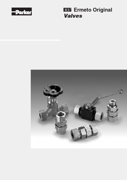
Female NPT thread (SAE 476) / Female NPT thread (SAE 476)
Visual index 3/2-way ball valves
KH 3/2 (S) p. O42
EO 24° cone end / EO 24° cone end / EO 24° cone end
KHBLOCK p. O51
Ball valve with Flange connection DIN EN 1092-1
2/2-way ball valve for block structure
O6
Catalogue 4100-8/UK
Visual index shut off valves and Line Rupture Valves “LRV”
DV p. O52
Valves
LD p. O53
EO 24° cone end / EO 24° cone end
VDHA p. O54
EO 24° cone end / EO 24° cone end
EO tube end / EO tube end
WV p. O55
ELA/ELAE p. O57
KH-A-S-71 p. O48
Ball valve with SAE Flange connection
KH-B4V-S p. O49
Ball valve with SAE Flange adapter connection
KHB5V-S p. O50
Ball valve with SAE Flange connection ISO 6162 (1/2)
派克阀样本手册软件版9

(2) In
(1) Out
Dimensions Millimeters (Inches)
DL081K
Ø 12.6 (.48)
(1)
27.8 (1.09)
(2)
39.3 (1.55)
Ø 25.4 (1.0)
3/4-16 UNF-2A Thread
Ø 2.4 (.09) Thru For Roll Pin Attachment 1/4-20 UNC-2A Thread
DMH085C2 ....... C08-4 .......... 3 Position, 4 Way, Open Center,
.............................................. Pull to Shift and Push to Shift ........................... 15/4 ...... 350/5000 ........ MV11-MV12 PV
PSI Bar 100 6.9
Hydraulic Oil 150 SSU @ 100°F (32 cSt)
Pressure Drop ( P)
75 5.1
50 3.5
25 1.7
0 LPM
0 GPM
7.6
15.1
22.7
30.3
2
4
6
8
Flow (Q)
Specifications
Out (1) In (2)
32.2 (1.27)
Detent Position
54.6 (2.15)
31.8 (1.25)
28.2 (1.11)
7/8" Hex. 20 Nm (15 lb. ft.) Torque
派克比例阀英文样本

PID00A-40*
Servo Drives for Positions-/Power Control
Compax 3F
News in Electrohydraulics
Details
Characteristics Ordering Code Technical Data Characteristic Curves Dimensions Characteristics Ordering Code Technical Data Characteristic Curves Dimensions Characteristics Ordering Code Technical Data Characteristic Curves Dimensions Characteristics Ordering Code Technical Data Characteristic Curves Dimensions Characteristics Technical Data, Ordering Code Construction Interface Program Characteristics Technical Data, Ordering Code Construction Interface Program Characteristics Technical Data, Ordering Code Construction Interface Program Characteristics Technical Data, Ordering Code Construction Interface Program Characteristics Technical Data, Ordering Code Construction Interface Program General Ordering Code Technical Data Technology Functions Interfaces / Multi-Axis Control Software Tools Dimensions / Accessories
parker微型多介质流体阀

• 提供高化学兼容性,PTFE和硼硅酸盐玻璃材质能适用多种化学流体 • 在最高环境温度66˚C中,也能100%连续负载工作 • 低功耗降低发热和能耗 • 快速响应时间确保精确的可重复性的结果 • 直动式操作不需要任何正压或负压驱动 • 100%泄漏测试保证密封的质量 • 为您的仪器设备提供高可靠性
part number 002-0017-900 2ཚԿ ᅂ༹ࢅഘ༹
24” Hg- 20 psi 0.060" PTFE 12 VDC 1/4 - 28 40 - 150 deg F PTFE
002-0010-900 2ཚԿ ᅂ༹ࢅഘ༹
24” Hg - 20 psi 0.060" PTFE 24 VDC 1/4 - 28 40 - 150 deg F PTFE
1600 1400 1200 1000 800 600 400 200
0 0
8
SERIES 3ୁ
0.055" Orifice 0.078" Orifice 0.090" Orifice
20
40
60
80
100
უ૰(PSI)
通用 Series 3
尺寸图
PORTS
A
1/16 BARBS 1.86
1/8 BARBS 2.03
3/16 BARBS 2.13
10 - 32
1.68
订货信息
尺寸图,0.60"孔径
三通
B
C
D
0.16
0.98
0.17
0.16
1.02
0.35
0.16
1.32
0.44
0.22
0.81
N/A
Parker Hannifin 公司 D FC 和 D 1FC 电容式阀门系列用户指南说明书
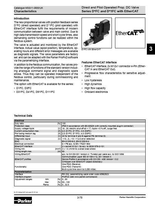
D_FC EtherCAT UK.indd 27.07.223-75Parker Hannifin Corporation3IntroductionThe new proportional valves with position feedback series D*FC (direct operated) and D*1FC (pilot operated) with EtherCAT interface fulfill the requirements of modern communication between valve and main control. Due to high data transmission speed and short cycle times, also demanding control functions can be realized within the fieldbus system.The valve is actuated and monitored by the EtherCAT interface. Actual value (spool position), temperature, op -erating hours and different error messages are available as diagnostic signals. The valve parameters are factory set and can be adapted with the Parker ProPxD software via the parametrizing interface.In addition to the fieldbus communication, the valves pro -vide the range of functions of the standard version includ-ing analogue command signal and diagnostic spare stroke. Thus they can be operated independent of the fieldbus control, particularly during commissioning and maintenance.The option with EtherCAT is available for the series: • D1FC, D3FC• D31FC, D41FC, D91FC, D111FCTechnical DataFeatures EtherCAT interface• EtherCAT interface, 2x M12x1 connector 4-Pin (Ether -CAT In and EtherCAT Out)• Progressive flow characteristics for sensitive adjust -ment• Low hysteresis •High dynamics • High flow capacity• Onboard electronicsD1FC with EtherCATDirect and Pilot Operated Prop. DC Valve Series D*FC and D*1FC with EtherCATD_FC EtherCAT UK.indd 27.07.223-76Catalogue MSG11-3500/UKParker Hannifin Corporation3Ordering CodeHigh dynamicsCF DC N09Direct Operated Proportional DC ValveCode Size 1NG06 / CETOP 033NG10 / CETOP 05DC valveSizeCode Size3NG10 / CETOP 054NG16 / CETOP 079NG25 / CETOP 0811NG32 / CETOP 10CF 1DCPilot Operated Proportional DC ValveN00DC valveSpool position on power downSpool typeDesign series(not required for ordering)SealsSizeDrain port Y(plugged)Proportional control EtherCAT interfaceSee ordering code for valve series without EtherCATNG06 pilot valve Function FlowPilot connection EtherCAT interfaceSpool position on power downDesign series(not required for ordering)Seals Proportional control Integrated electronics with positionfeedbackSee ordering code for valve series without EtherCATPlease order connector separately, see chapter 3 accessories.Parametrizing cable OBE ® RS232, item no. 40982923Spool/body design3Direct and Pilot Operated Prop. DC Valve Series D*FC and D*1FC with EtherCATD_FC EtherCAT UK.indd 27.07.223-77Catalogue MSG11-3500/UKParker Hannifin Corporation3Block Diagram / DimensionsBlock diagramDimensions D1FC with EtherCAT。
Parker Hannifin FDC101流量分配 合并阀门系列技术数据说明书

Manual Valves
Operating Temp. -40°C to +93.3°C (Nitrile)
SV
Range (Ambient) (-40°F to +200°F) -31.7°C to +121.1°C (Fluorocarbon)
(-25°F to +250°F)
Solenoid Valves
(3)
• Pressure compensated control in both directions
• 50/50 ratio standard, other ratios available on request
• FC
Commonly used for differential lock in transmission
B64 15.0 LPM ( 4 GPM) min. inlet 37.5 LPM (10 GPM) max. inlet 60% ‘4’ Port and 40% ‘2’ Port
D63 11.3 LPM (3 GPM) min. inlet 33.8 LPM (9 GPM) max. inlet 33% ‘4’ Port and 66% ‘2’ Port
B10-4-6T body — 6HP*50-S B10-4-8T body — 8HP*50-S B10-4-4P body — 102 x 4 B10-4-6P body — 102 x 6 B10-4-8P body — 102 x 8
When machining a manifold using the FDC101, use C10-4 cavity. Do not machine a port that directs flow to the nose of the cavity.
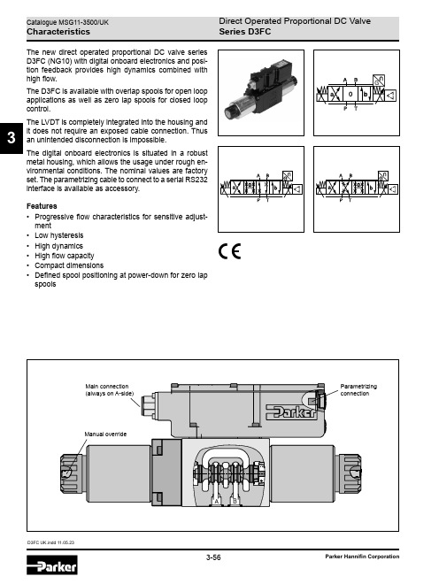
Parker Hannifin 直压比例电机阀D3FC系列(NG10)商品说明说明书
D3FC UK.indd 11.05.233The new direct operated proportional DC valve series D3FC (NG10) with digital onboard electronics and posi-tion feedback provides high dynamics combined with high flow.The D3FC is available with overlap spools for open loop applications as well as zero lap spools for closed loop control.The LVDT is completely integrated into the housing and it does not require an exposed cable connection. Thus an unintended disconnection is impossible.The digital onboard electronics is situated in a robust metal housing, which allows the usage under rough en-vironmental conditions. The nominal values are factory set. The parametrizing cable to connect to a serial RS232 interface is available as accessory.Features• Progressive flow characteristics for sensitive adjust -ment• Low hysteresis • High dynamics • High flow capacity • Compact dimensions• Defined spool positioning at power-down for zero lapspoolsSeries D3FCD3FC UK.indd 11.05.233Ordering CodeDirectSize Propor-Spool1)On power down the spool moves in a defined position. This cannot be guaranteed in case of single flow path on the control edge A – T resp. B – T with pressure drops above 120 bar or contamination in the hydraulic fluid.2)Approx. 10 % opening, only zero lap spools.3)Only for overlap spools.4)Plug in port Y needs to be removed at tank pressure >35 bar. 5)Please order connector separately, see chapter 3 accessories.High D 3F 93CParametrizing cable OBE ® RS232, item no. 40982923Series D3FCD3FC UK.indd 11.05.233Technical Data2)Flow rate for different D p per control edge: Q x = Q Nom. · √D p x D p Nom.1)If valves with onboard electronics are used in safety-related parts of control systems, in case the safety function is requested, the valve elec-tronics voltage supply is to be switched off by a suitable switching element with sufficient reliability.Series D3FCD3FC UK.indd 11.05.233Characteristic CurvesAll characteristic curves measured with HLP46 at 50 °C.Flow characteristics(Electrically set to opening point 10 %) at D p = 5 bar per metering edge Spool type E01Spool type B31Spool type E50Spool type B60Series D3FCD3FC UK.indd 11.05.233All characteristic curves measured with HLP46 at 50 °C.Frequency± 5 %, ± 25 %, ± 90 % input signalStep responseFunctional limits25 %, 50 %, 75 % and 100 % command signal (symmetric flow). At asymmetric flow a reduced flow limit has to be considered.Spool type E01MSpool type E01SSpool type E01UCharacteristic CurvesSeries D3FCD3FC UK.indd 11.05.233Code 511 + PE acc. to EN 175201-8043 m length0...±20 mAE:S:Code 0, 36 + PE acc. to EN 175201-804Block DiagramsCode 1, 76 + PE acc. to EN 175201-804 + enable3 m length0...±20 mAE:S:Series D3FCD3FC UK.indd 11.05.233Interface ProgramProPxD interface programThe ProPxD software permits comfortable parameter setting for the module electronics. Via the clearly arranged entry mask the parameters can be noticed and modified. Storage of complete parameter sets is possible as well as printout or record as a text file for further documenta -tion. Stored parameter sets may be loaded anytime and transmitted to other valves. Inside the electronics a non-volatile memory stores the data with the option for recall-ing or modification.The PC software can be downloaded free of charge at /propxd.Features• Comfortable editing of all parameters• Depiction and documentation of parameter sets • Storage and loading of optimized parameter adjust -ments• Executable with all actual Windows ® operating systems from Windows ® XP upwards• Plain communication between PC and electronics via serial interface RS232CThe parametrizing cable may be ordered under item no. 40982923.Series D3FCD3FC UK.indd 11.05.233DimensionsPort Y plugged。
Parker Hannifin Corporation 2F1C 2-路流量控制阀门产品介绍说明书

Series 2F1CTechnical Information General DescriptionSeries 2F1C 2-way flow control valves provide pres-sure and viscosity compensated flow from port A to port B. The counter direction is blocked (standard) or can be open via an integral reverse flow check valve (optional).OperationThe compensator spool is located in front of the meter-ing spool. The metering spool is closed in the neutral position to avoid undesired initial actuator motion. The oil flow to open the metering spool has to pass a needle valve (not shown in the sectional drawing). The needle valve can be adjusted from the front panel to set the response time of the 2F1C.The metering spool is adjusted by the main control knob. The key lock has three positions:Lock: Adjustment is locked.Adjust: Full adjustment is permitted.T rim:Fine adjustment of ±5% is possible.Features• 2 way flow control valve.• Subplate mounting according to ISO 6263.• Excellent fine adjustment.• Adjustable response time.• Closed in neutral position.• Optional reverse flow check valve.•2 sizes: NG10 (3/8"), NG16 (3/4").SpecificationsSize NG10NG16Actuator Manual flow rate adjustmentMounting Type ISO 6263Mounting Position UnrestrictedFluid Temperature +70°C (+158°F) Maximum Ambient Temprature -25°C to +50°C (-13°F to +122°F)Viscosity Range 2.8 to 400 cSt (mm 2/s)Filtration15 µm Maximum Pressure DifferenceSee DiagramMaximum Operating Pressure Port A Port B2F1C0214 - 280 Bar (203 - 4060 PSI) 0 - 270 Bar (0 - 3915 PSI)2F1C0314 - 350 Bar (203 - 5075 PSI) 0 - 340 Bar (0 - 4930 PSI)Flow DirectionA–B B–A Flow control functionBlocked or free flow through check valveSeries 2F1COrdering Information Weight:2F1C02 6.0 kg (13.2 lbs.)2F1C03 9.0 kg (19.8 lbs.)2-Way Flow Control ValveNominal SizeAdjustment Knob with LockDesign SeriesOptions2F1CCode Description 02 NG10 (3/8") 03 NG16 (3/4")Code Description 0 Without Check C With CheckSeal01BFluorocarbonReverse Flow Check52F1C022F1C032F1C022F1C032F1C022F1C03Series 2F1CInch equivalents for millimeter dimensions are shown in (**)Size ISO-code x1x2x3x4x5x6y1y2y3y4y5026263-AM-07-2-A76.2(3.00)79.4(3.13)9.5(0.37)44.5(1.75)19.0(0.75)–82.5(3.25)23.8(0.94)30.2(1.19)41.3(1.63)39.7(1.56)036263-AK-06-2-A 101.6(4.00)103.2(4.06)20.6(0.81)52.4(2.06)31.8(1.25)0.8(0.03)101.6(4.00)28.6(1.13)15.1(0.59)75.4(2.97)26.2(1.03)Size ISO-code B1B2H1H2H3L1L2d1d2d3d4026263-AM-07-2-A 101.6(4.00)38.1(1.50)119.6(4.71)87.4(3.44)6.4(0.25)95.2(3.75)47.6(1.87)6.4(0.25)57.2(2.25)8.7(0.34)14.2(0.56)036263-AK-06-2-A 123.8(4.87)42.9(1.69)121.4(4.78)89.2(3.51)6.4(0.25)123.8(4.87)61.9(2.44)9.5(0.37)57.2(2.25)10.5(0.41)22.4(0.88)Dimensions。
Parker Hannifin 流控制阀门系列F的技术信息说明书
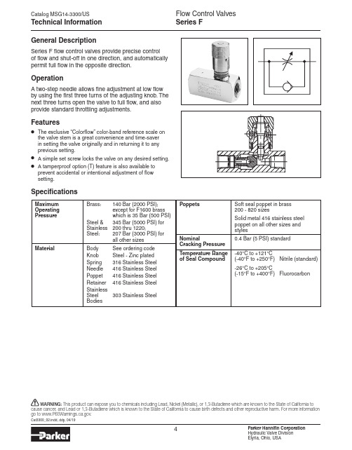
Technical Information Series FGeneral DescriptionSeries F flow control valves provide precise control of flow and shut-off in one direction, and automatically permit full flow in the opposite direction.OperationA two-step needle allows fine adjustment at low flow by using the first three turns of the adjusting knob. The next three turns open the valve to full flow, and also provide standard throttling adjustments.Features• The exclusive “Colorflow” color-band reference scale on the valve stem is a great convenience and time-saver in setting the valve originally and in returning it to any previous setting.• A simple set screw locks the valve on any desired setting.• A tamperproof option (T) feature is also available toprevent accidental or intentional adjustment of flow setting.SpecificationsMaximumBrass: 140 Bar (2000 PSI); Operating except for F1600 brass Pressurewhich is 35 Bar (500 PSI) Steel &345 Bar (5000 PSI) for Stainless 200 thru 1220;Steel: 207 Bar (3000 PSI) forall other sizesMaterial Body See ordering code Knob Steel - Zinc plated Spring 316 Stainless Steel Needle 416 Stainless Steel Poppet 416 Stainless Steel Retainer 416 Stainless Steel Stainless Steel 303 Stainless SteelBodiesPoppets Soft seal poppet in brass 200 - 820 sizesSolid metal 416 stainless steel poppet on all other sizes andstylesNominal0.4 Bar (5 PSI) standardCracking Pressure Temperature Range -40°C to +121°Cof Seal Compound (-40°F to +250°F) Nitrile (standard) -26°C to +205°C(-15°F to +400°F) FluorocarbonThis product can expose you to chemicals including Lead, Nickel (Metallic), or 1,3-Butadiene which are known to the State of California to go to .Code Description O mit Standard 4 Fine Metering (200, 400, 420, 600, 620, 820 sizes)Code Description B Brass S Steel SS* Stainless Steel Code Description Omit NPTF/SAE ★8 BSPT ★★9 BSPPFOptionsSeriesSizeMaterialNeedle Options Other Options Seal CompoundDesign Series NOTE: Not required when ordering.* Not available above 1200 size.Code Description Omit Standard Knob T * Tamperproof F Finger ScrewOrdering InformationSeries F200 * 1/8" 400 *† 1/4" 420 #4 SAE 600 *† 3/8" 620 #6 SAE 800 *† 1/2"820 *† #8 SAE 1020 #10 SAE 1200 * 3/4"1220 #12 SAE 1600 * 1"1620 #16 SAE2000 1 1/4"2020 #20 SAE 2400 1 1/2"2420 #24 SAE 3200 2"3220 #32 SAE* Sizes available in Brass.† Sizes available in Stainless Steel.Code Size Code Size Code Size ★ Code 8 can be used withsizes 200, 400, 600, 800, 1200 Steel only★★ Code 9 can be used withsizes 200, 400, 600, 800, 1200, 1600, 2000, 2400.Effective Free Flow Free Flow Orifice Area, Effective Model Rate, Max. Orifice Area Free Flow Control Flow Control FlowNumber LPM (GPM) in. 2 C v in. 2 C vF200 11 (3) 0.023 0.53 0.0102 0.230 F420 11 (3) 0.023 0.53 0.0102 0.230 F400 19 (5) 0.068 1.56 0.0194 0.433 F620 19 (5) 0.068 1.56 0.0194 0.433 F600 30 (8) 0.099 2.27 0.0344 0.787 F820 30 (8) 0.099 2.27 0.0344 0.787 F800 57 (15) 0.224 5.11 0.0427 0.976 F1020 57 (15) 0.224 5.11 0.0427 0.976 F1200 95 (25) 0.348 7.95 0.1080 2.470 F122095 (25)0.3487.950.10802.470F1600 151 (40) 0.453 10.35 0.2300 5.250 F1620 151 (40) 0.453 10.35 0.3070 7.000 F2000 265 (70) 0.855 19.52 0.2300 5.250 F2020 265 (70) 0.855 19.52 0.3710 8.470 F2400 379 (100) 0.955 21.82 0.2300 5.250 F2420 379 (100) 0.955 21.82 0.3710 8.470 F3200 568 (150) 1.046 23.90 0.2300 5.250 F3220568 (150)1.04623.900.601013.410Series F Brass and Stainless Steel Valves can be used for both air and oil service.* Available in 400, 600 800, and 820 sizes only.Code DescriptionOmit Nitrile (Standard) V Fluorocarbon (Standard on S tainless Steel)Model Number Effective Orifice Area Control Flow in.2 Effective Control FlowC vF400-40.00440.0758F600-40.00970.153F620-40.00440.0758F820-40.00970.153Performance Curves Series FInch equivalents for millimeter dimensions are shown in (**)HEDCClosedBOpenGF Sq.A (Both Ends)G FASTControlled FlowKnob OptionsPinTamperproofOption (Code “T”)permanently locksknob at desiredflow setting byinstalling a pin inpredrilled hole.Finger screwOption (Code“F”) providesthis thumb-screw in placeof set screw.Dimensions Series FModel WeightNumber kg (lbs) A B C D E F G HF2000.1(0.3)1/8–27NPTF 39.1 35.3 50.8 32.5 16.0 7.9 19.1(1.54) (1.39) (2.00) (1.28) (0.63) (0.31) (0.75)F4000.2(0.5)1/4–18NPTF 45.5 40.4 66.8 42.2 20.6 10.4 20.6(1.79) (1.59) (2.63) (1.66) (0.81) (0.41) (0.81)F4200.2(0.5)7/16–20UNF 41.4 37.6 68.3 42.9 20.6 10.4 19.1#4SAE (1.63) (1.48) (2.69) (1.69) (0.81) (0.41) (0.75)F6000.3(0.7)3/8–18NPTF 55.4 49.5 69.9 44.5 25.4 12.7 25.4(2.18) (1.95) (2.75) (1.75) (1.00) (0.50) (1.00)F6200.3(0.7)9/16–18UNF 47.7 42.7 79.2 48.8 25.4 12.7 20.6#6SAE (1.88) (1.68) (3.12) (1.92) (1.00) (0.50) (0.81)F800 0.7(1.5)1/2–14NPTF 68.6 61.5 87.4 56.6 31.8 16.0 30.2(2.70) (2.42) (3.44) (2.23) (1.25) (0.63) (1.19)F8200.5(1.1)3/4–16UNF 56.9 51.1 88.9 53.8 28.4 14.2 25.4#8SAE (2.24) (2.01) (3.50) (2.12) (1.12) (0.56) (1.00)F1020 0.8(1.8)7/8–14UNF 68.6 61.5 101.6 65.0 31.8 15.7 30.2#10SAE (2.70) (2.42) (4.00) (2.56) (1.25) (0.62) (1.19)F1200 1.2 (2.6)3/4–14NPTF 85.9 71.4 98.6 65.5 38.1 19.1 35.1(3.38) (2.81) (3.88) (2.58) (1.50) (0.75) (1.38)F1220 1.2 (2.6) 1 1/6–12 UN 85.9 71.4 117.3 76.5 38.1 19.1 35.1#12SAE (3.38) (2.81) (4.62) (3.01) (1.50) (0.75) (1.38)F1600 2.3 (5.1) 1–11 1/2 NPTF 123.7 106.9 127.0 81.8 44.5 22.4 47.8(4.87) (4.21) (5.00) (3.22) (1.75) (0.88) (1.88)*F1620 2.3 (5.1) 1 5/16–12 UN 130.8 114.0 142.7 88.9 57.2 28.4 47.8#16SAE (5.15) (4.49) (5.62) (3.50) (2.25) (1.12) (1.88)*F2000 3.7 (8.2) 1 1/4–11 1/2 NPTF 130.0 113.3 143.0 98.6 57.2 28.7 47.8(5.12) (4.46) (5.63) (3.88) (2.25) (1.13) (1.88)*F2020 3.7 (8.2) 1 5/8–12 UN 140.2 123.4 165.1 108.0 69.9 35.1 47.8#20SAE (5.52) (4.86) (6.50) (4.25) (2.75) (1.38) (1.88)*F2400 4.6 (10.2) 1 1/2–11 1/2 NPTF 136.4 119.6 143.0 113.5 69.9 35.1 47.8(5.37) (4.71) (5.63) (4.47) (2.75) (1.38) (1.88)*F2420 4.6 (10.2) 1 7/8–12 UN-2B 143.5 126.7 184.2 127.0 76.2 38.1 47.8#24SAE (5.65) (4.99) (7.25) (5.00) (3.00) (1.50) (1.88)*F3200 7.9 (17.4) 2–11 1/2 NPTF 146.1 129.3 165.1 134.9 88.9 44.5 47.8(5.75) (5.09) (6.50) (5.31) (3.50) (1.75) (1.88)*F3220 7.9 (17.4) 2 1/2–12 UN 163.6 139.4 228.6 155.7 101.6 50.8 47.8#32SAE (6.44) (5.49) (9.00) (6.13) (4.00) (2.00) (1.88)**=Hex。
Parker插装阀样本-逻辑阀LEsection
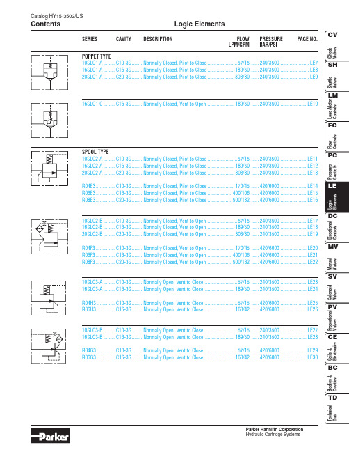
Catalog HY15-3502/USLogic Elements ContentsParker Hannifin CorporationSERIES CAVITY DESCRIPTION FLOW PRESSURE PAGE NO.LPM/GPM BAR/PSIPOPPET TYPE10SLC1-A.........C10-3S........Normally Closed, Pilot to Close.......................57/15......240/3500......................LE7 16SLC1-A.........C16-3S........Normally Closed, Pilot to Close.....................189/50......240/3500......................LE8 20SLC1-A.........C20-3S........Normally Closed, Pilot to Close.....................303/80......240/3500......................LE916SLC1-C.........C16-3S........Normally Closed, Vent to Open.....................189/50......240/3500....................LE10SPOOL TYPE10SLC2-A.........C10-3S........Normally Closed, Pilot to Close.......................57/15......240/3500....................LE11 16SLC2-A.........C16-3S........Normally Closed, Pilot to Close.....................189/50......240/3500....................LE12 20SLC2-A.........C20-3S........Normally Closed, Pilot to Close.....................303/80......240/3500....................LE13R04E3...............C10-3S........Normally Closed, Pilot to Close.....................170/45......420/6000....................LE14 R06E3...............C16-3S........Normally Closed, Pilot to Close..................400/106......420/6000....................LE15 R08E3...............C20-3S........Normally Closed, Pilot to Close..................500/132......420/6000....................LE1610SLC2-B.........C10-3S........Normally Closed, Vent to Open.......................57/15......240/3500....................LE17 16SLC2-B.........C16-3S........Normally Closed, Vent to Open.....................189/50......240/3500....................LE18 20SLC2-B.........C20-3S........Normally Closed, Vent to Open.....................303/80......240/3500....................LE19R04F3...............C10-3S........Normally Closed, Vent to Open.....................170/45......420/6000....................LE20 R06F3...............C16-3S........Normally Closed, Vent to Open..................400/106......420/6000....................LE21 R08F3...............C20-3S........Normally Closed, Vent to Open..................500/132......420/6000....................LE2210SLC3-A.........C10-3S........Normally Open, Vent to Close.........................57/15......240/3500....................LE23 16SLC3-A.........C16-3S........Normally Open, Vent to Close.......................189/50......240/3500....................LE24R04H3..............C10-3S........Normally Open, Vent to Close.........................57/15......420/6000....................LE25 R06H3..............C16-3S........Normally Open, Vent to Close.......................160/42......420/6000....................LE2610SLC3-B.........C10-3S........Normally Open, Vent to Close.........................57/15......240/3500....................LE27 16SLC3-B.........C16-3S........Normally Open, Vent to Close.......................189/50......240/3500....................LE28R04G3..............C10-3S........Normally Open, Vent to Close.........................57/15......420/6000....................LE29 R06G3..............C16-3S........Normally Open, Vent to Close.......................160/42......420/6000....................LE30LE1Logic ElementsCatalog HY15-3502/USTechnical TipsParker Hannifin CorporationCatalog HY15-3502/USLogic Elements Technical TipsParker Hannifin CorporationLE2LE3Logic ElementsCatalog HY15-3502/USTechnical TipsParker Hannifin CorporationCatalog HY15-3502/USLogic Elements Technical TipsParker Hannifin CorporationLE4LE5Logic ElementsCatalog HY15-3502/USTechnical TipsParker Hannifin CorporationDIRECTIONAL CONTROL EXAMPLESTHREE-WAY BRIDGE CIRCUITS Circuit 1, with **SLC1A poppet logic element.Circuit 2, with **SLC2A/R0*E3spool logic element.Circuit 3, with **SLC2A/R0*E3spool logic element.NOTE: Pilot pressure must exceed load pressure in order for valve to close.FOUR-WAY BRIDGE CIRCUITSCircuit 1, with **SLC1A poppet logic elements.Circuit 2, with **SLC2A/R0*E3 spool logic elements.Required Flow PathPilot Pressure Applied To PA PB 123Available From CircuitNONOXXYESNO X X XRequired Flow PathPilot Pressure Applied To PA PB 123Available From CircuitNOYESXXNO YES X XPilot Pressure Applied To P1P2P3P4P5Required Flow PathPilot Pressure Applied To P1P2P3P4P5Required Flow PathPilot Pressure Applied To P1P2P3P4P5Required Flow PathYES YES YES YES YESNO NO NO NO NOYES YESNO NO NONONO YES YES NOYES YES YES YESNOYESNONOYES YESNO YES YES NO YESYES YES NO YES YESNO YES YES YES YESNO YES NO YES YESYESNOYESNOYESYES YES YES NO YESYES NO YES YES YESP APBBACBAP APB CPB BP A ACABC ABCABC ABCPP5TP1P2A P3BP4P2A P1PP5TP4BP3ABP T ABPTABP T ABPTABP T ABP T ABP T ABP T ABP T ABPTABP T ABP T ABP T NOTE: Pilot pressure must exceed load pressure in order for valve to close.Catalog HY15-3502/USLogic Elements Technical TipsParker Hannifin CorporationLE6LE7Catalog HY15-3502/USPoppet Type Logic Valve Series 10SLC1-AParker Hannifin CorporationTechnical Information(3)Poppet Type Logic ValveSeries 16SLC1-A Catalog HY15-3502/USParker Hannifin CorporationTechnical Information(3)(2)LE8LE9Catalog HY15-3502/USPoppet Type Logic Valve Series 20SLC1-AParker Hannifin CorporationTechnical Information(1)(3)(2)Poppet Type Logic ValveSeries 16SLC1-C Catalog HY15-3502/USParker Hannifin CorporationTechnical Information(3)(2)LE10LE11Catalog HY15-3502/USSpool Type Logic Valve Series 10SLC2-AParker Hannifin CorporationTechnical InformationSpool Type Logic ValveSeries 16SLC2-A Catalog HY15-3502/USParker Hannifin CorporationTechnical Information(1)(3) (2)LE12LE13Catalog HY15-3502/USSpool Type Logic Valve Series 20SLC2-AParker Hannifin CorporationTechnical InformationSpool Type Logic ValveSeries R04E3Catalog HY15-3502/USParker Hannifin CorporationTechnical InformationLE14LE15Catalog HY15-3502/USSpool Type Logic Valve Series R06E3Parker Hannifin CorporationTechnical InformationSpool Type Logic ValveSeries R08E3Catalog HY15-3502/USParker Hannifin CorporationTechnical InformationLE16LE17Catalog HY15-3502/USSpool Type Logic Valve Series 10SLC2-BParker Hannifin CorporationTechnical Information(1)(3) (2)LE18Parker Hannifin CorporationLE19Parker Hannifin CorporationSeries R04F3Parker Hannifin CorporationTechnical InformationLE20LE21Parker Hannifin CorporationSeries R08F3Parker Hannifin CorporationTechnical InformationLE22LE23Parker Hannifin CorporationSeries 16SLC3-AParker Hannifin CorporationTechnical Information(2)(3) (1)LE24LE25Parker Hannifin CorporationSeries R06H3Parker Hannifin CorporationTechnical InformationLE26LE27Parker Hannifin CorporationLE28Series 16SLC3-BParker Hannifin CorporationTechnical Information (2)(3)(1)LE29Parker Hannifin CorporationLE30Spool Type Logic Valve Series R06G3Catalog HY15-3502/USParker Hannifin CorporationHydraulic Cartridge SystemsTechnical Information。
PARKER 螺纹插装阀 ------- 逻辑元件经典应用组合

LOGIC CIRCUITSLogic (from the Greek λογική logikē)Normally Open Controlled w/ 2-Way, 2 PositionDSL102N16SLC1-B-**BDIRECTION OF FLOWANormally Open Controlled w/ 2-Way, 2 PositionDSL102NWith the solenoid valve de-energized the spring chamber of the LE vents to tank and thus the poppet shifts allowing flow from port ‘1’ to ‘2’16SLC1-B-**SYSTEM50 GPM 3000 PsiNormally Open Controlled w/ 2-Way, 2 PositionDSL102NWhen Solenoid Valve is energized, the spring chamber of the LE is blocked. Then the spring chamber is pressurized and the LE closes (2:1 ratio)16SLC1-B-**SYSTEM50 GPM 3000 PsiNormally Open Controlled with 2-Way, 2 Position and “SLC1-C” LEDSL102NA16SLC1-C-**DIRECTION OF FLOWBNormally Open Controlled with 2-Way, 2 Position and “SLC1-C” LEDSL102NWith the solenoid valve de-energized the spring chamber of the LE vents to tank and thus the poppet shifts allowing flow from port ‘2’ to ‘1’50 GPM 3000 Psi16SLC1-C-**SYSTEMNormally Open Controlled w/ 2-Way, 2 Position and “SLC1-C” LEDSL102NWhen Solenoid Valve is energized, the spring chamber of the LE is blocked. Then the spring chamber is pressurized and the LE closes (2:1 ratio)16SLC1-C-**SYSTEM50 GPM 3000 PsiNormally Open External Pilot Controlled w/ 2-Way, 2 PositionPilotBA Direction of FlowNormally Open Controlled w/3-Way, 2 Position SVDSL103BLE20SLC1-A-25BDIRECTION OF FLOWPilotANormally Open Controlled w/3-Way, 2 PositionWith the SV deenergized: •The external pilot pressure is blocked. •The spring chamber of LE the LE vents to tank 20SLC1-A-25 thru SV and thus the poppet shifts allowing flow from ‘A’ to ‘B’ or vice versa.ADSL103BSVBDIRECTION OF FLOWPilotNormally Open Controlled w/3-Way, 2 PositionSVWhen SV is energized, the LE external pilot 20SLC1-A-25 pressurizes the spring chamber of LE. Then the LE closes (2:1 ratio), so no flow passes thru.ADSL103BBDIRECTION OF FLOWPilotNormally Open Controlled w/3-Way, 2 Position & Shuttle ValveSVDSL103BLE20SLC1-A-25BSHCS041BDIRECTION OF FLOWANormally Open Controlled w/3-Way, 2 Position & Shuttle ValveWith the SV deenergized: •The spring chamber of LE vents to tank thru SV and thus the poppet shifts allowing flow from ‘A’ to ‘B’ or vice versa. •The pressure sensed by SH valve is blocked.ASVDSL103BLEBSHCS041BDIRECTION OF FLOWNormally Open Controlled w/3-Way, 2 Position & Shuttle ValveDSL103BWith SV Energized: •The pressure sensed by SH valve passes thru SV and pressurizes the spring chamber of LE . •Then the LE closes (2:1 ratio), so no flow passes thru.ASVLE20SLC1-A-25BSHCS041BDIRECTION OF FLOWHigh Flow Soft Shift, 2-Way, 2 Position Normally ClosedBDIRECTION OF FLOWSVDSL103N Ų .020 Ų .030 Ų .035LE1LE2LE3SH20SLC1-A-150 20SLC1-A-75 20SLC1-A-25 CS041BAHigh Flow Soft Shift, 2-Way, 2 Position Normally Closed The SH valve willWith SV De-energized, all spring chambers on the Logic Elements are Blocked and thus no flow from “A” to “B” or vice versa.Bsend pilot flow from whatever direction the flow is coming from.DIRECTION OF FLOWSVDSL103N Ų .020 Ų .030 Ų .035LE1LE2LE3SH20SLC1-A-150 20SLC1-A-75 20SLC1-A-25 CS041BAHigh Flow Soft Shift, 2-Way, 2 Position Normally ClosedWith SV Energized, all spring chambers on the Logic Elements vent to tank thru SV. This allows flow from “A” to “B” or vice versa. The SH valve senses flow from “A” but is blocked..BDIRECTION OF FLOWSVDSL103N Ų .020 Ų .030 Ų .035LE1LE2LE3SH20SLC1-A-150 20SLC1-A-75 20SLC1-A-25 CS041BAHigh Flow SelectorA BLE1LE2SV20SLC1-A-5020SLC1-A-50DSL104BSUPPLYHigh Flow SelectorA BLE120SLC1-A-50LE2With SV Deenergized: •LE1 spring chamber vents to tank, then valve opens allowing flow to “A”. •LE2 spring chamber is pressurized, then valve closes.80 GPM 3000 PsiSVDSL104BHigh Flow SelectorA BLE1LE220SLC1-A-50With SV Energized: •LE1 spring chamber is pressurized, then valve closes. •LE2 spring chamber vents to tank, then valve opens allowing flow to “B”.80 GPM 3000 PsiSVDSL104B。
美国派克PARKER插装阀的安装与拆卸
美国派克PARKER插装阀的安装与拆卸根据派克PARKER插装阀安装方式的不同,插装阀可以分为二通插装阀和螺纹插装阀。
二通插装阀的安装方式是采用螺钉压入(或敲击滑入)阀块的插孔里,只有开和关两种状态,也叫作逻辑阀,它的最小通径为16mm,最大通径为160mm,常用通径为16mm、25mm、32mm、40mm、50mm、63mm、80mm、100mm、125mm、160mm,最高工作压力为42MPa,最大流量为25000L/min,适合于高压大流量的液压系统。
螺纹插装阀的安装方式是采用螺纹直接旋入阀块的插孔里,所以又叫旋入式插装阀,它的最小通径为3mm,最大通径为32mm,常用通径为4mm、8mm、10mm、12mm、16mm、20mm,最高压力可达63MPa,最大流量达760L/min,适合于中高压中小流量的液压系统。
目前,插装阀已广泛直用于工程机械中,在制造和维修工程机械的液压系统时离不开插装阀的安装,掌握其正确的安装方法才能确保液压系统的正常运行。
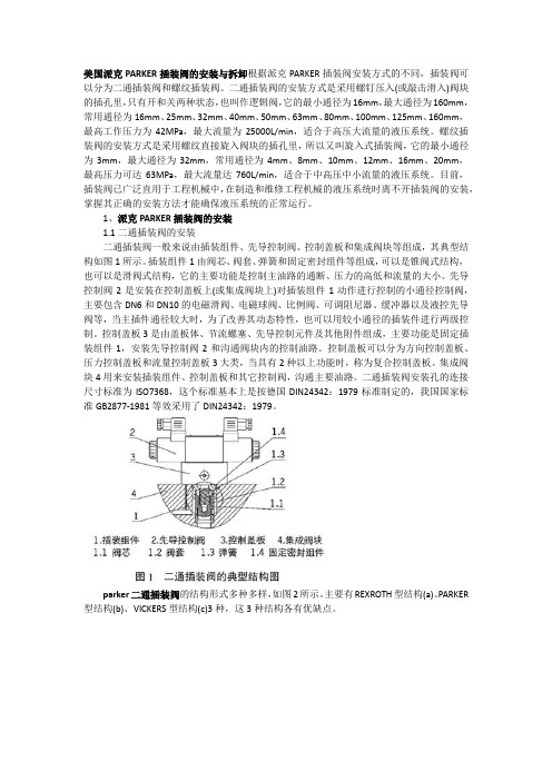
1、派克PARKER插装阀的安装1.1二通插装阀的安装二通插装阀一般来说由插装组件、先导控制阀、控制盖板和集成阀块等组成,其典型结构如图1所示。
插装组件1由阀芯、阀套、弹簧和固定密封组件等组成,可以是锥阀式结构,也可以是滑阀式结构,它的主要功能是控制主油路的通断、压力的高低和流量的大小。
先导控制阀2是安装在控制盖板上(或集成阀块上)对插装组件1动作进行控制的小通径控制阀,主要包含DN6和DN10的电磁滑阀、电磁球阀、比例阀、可调阻尼器、缓冲器以及液控先导阀等,当主插件通径较大时,为了改善其动态特性,也可以用较小通径的插装件进行两级控制。
控制盖板3是由盖板体、节流螺塞、先导控制元件及其他附件组成,主要功能是固定插装组件1,安装先导控制阀2和沟通阀块内的控制油路。
控制盖板可以分为方向控制盖板、压力控制盖板和流量控制盖板3大类,当具有2种以上功能时,称为复合控制盖板。
力士乐插装阀样本

1/2VSD-35004.15.04 - X - 99 - Z Relief, direct acting poppet type differential areaSpecial cavity, 004Flow is blocked from 2 to 1 until pressure increases to meet the selected valve setting, lifting the poppet from its seat and allowing relief flow through 1 to tank. Pressure at 1 is additive to the relief setting of the valve. The combination of stable poppet design and hardened seat provide excellent response, hysteresis and leakage characteristics.Technical dataDescriptionPerformanceRE 18318-22/09.09Replaces: RE 00162-02/01.06Max. operating pressureport 2 (P)bar (psi)210 (3000)Max. pressure admittedport 1 (T)bar (psi)140 (2000)Max. flow l/min. (gpm)350 (93)Max. internal leakage (*)drops/min.15Fluid temperature range°C (°F)-30 to 100 (-22 to 212)Installation torque Nm (ft-lbs)245-264 (181-196)Weight kg (lbs) 1.5 (3.3)Special cavity 004, see data sheet RE 18325-75Seal kit (**)code material no.RG0004020520100R930001696Fluids Mineral-based or synthetics with lubricating properties at viscosities of 10 to 500 mm 2/s (cSt)Filtration Nominal value max. 10µm (NAS 8)ISO 4406 19/17/14InstallationNo restrictionsOther Technical DataSee data sheet RE 18350-50(*) at 80% of pressure setting (**) Only external seals for 10 valves© This document, as well as the data, specifications and otherinformation set forth in it, are the exclusive property of Bosch Rexroth Oil Control S.p.a.. It may not be reproduced or given to third parties without its consent.The data specified above only serve to describe the product. Nostatements concerning a certain condition or suitability for a certain application can be derived from our information. The information given does not release the user from the obligation of own judgment and verification. It must be remembered that our products are subject to a natural process of wear and aging.Subject to change.Bosch Rexroth Oil Control S.p.A.Via Leonardo da Vinci 5P.O. Box no. 541015 Nonantola – Modena, Italy Tel. +39 059 887 611 Fax +39 059 547 848cartridges@ TypeMaterial number 04150403990500A R93000037704150403992000AR901113637Type Material numberDimensionsOrdering codeSeries 0/A to Lunchanged performances and dimensionsRelief, direct acting poppet type differential areaVersion and options standardSPRINGSAdjustmentsAdj. press. rangebar (psi)Pressure increase bar/turn (psi/turn)Std. setting bar (psi)(Q=5 l/min)= 03 Leakproof inner hex. socket screw= 0515-50 (220-725)9 (131)50 (725)Special cavity, 004= 2080-210 (1160-3000)37 (537)200 (2900)04.15.04X99Z00*Leakproof inner hex. socket screw。
Parker流量阀技术连接时的注意事项

Parker流量阀技术连接时的注意事项Parker流量阀技术连接时的注意事项Parker流量掌控阀是在肯定压力差下,依靠更改节流口液阻的大小来掌控节流口的流量,从而调整执行元件(液压缸或液压马达)运动速度的阀类。
重要包括节流阀、调速阀、溢流节流阀和分流集流阀等。
安装形式为水平安装。
其连接方式分为法兰式与螺纹式;焊接式。
PARKER流量掌控阀产品特点流量掌控阀又称400X流量掌控阀,是一种采纳高精度先导方式掌控流量的多功能阀门。
方式掌控流量的多功能阀门。
1、一改常规节流阀使用孔板或纯机械的减小流域面积的原理,利用相关导阀,zui大限度地减小能量在节流过程中的损失2、掌控灵敏度高,安全牢靠,调试简便,使用寿命长。
可在没有外接电源的情况下,自动实现系统的流量平衡。
是通过保持孔板(固定孔径)前后压差肯定而实现流量限定的,因此,也可称定流量阀。
定流量阀作用对象是流量,能够锁定流经阀门的水量,而不是针对阻力的平衡。
他能够解决系统的动态失调问题:为了保持单台制冷机、锅炉、冷却塔、换热器这些设备的高效率运行,就需要掌控这些设备流量固定于额定值;从系统末端来看,为了避开动态调整的相互影响,也需要在末端装置或分支处限制流量。
parker流量阀的工作原理流量阀是由一个手动调整阀组和一个自动平衡阀组构成。
调整阀组作用是设定流量,自动平衡阀组作用是维持流量恒定。
系统流体的工作压力为P1,手动调整阀的前后压力分别为P2、P3、当手动调整阀调到某一位置时,即人为确定了“设定流量”Kv即手动调整阀的流量系数,流量G=Kv(P2P3),Kv为,Kv设定后,只要P2-P3不变,则流量G不变。
当系统流量增大时,(P2—P3)的实际值超过了允许的给定值,此时通过感压膜和弹簧作用使自动调整阀组自动关小,直至流量重新维持到设定流量,反之亦然。
流量阀自动调整流量的有效范围取决于工作弹簧的性能。
一般流量阀前后压差在20—300kPa的范围内能按设定值有效掌控流量。
派克比例阀 D1FBE01FC0NF0016 - Parker派克

派克比例阀 D1FBE01FC0NF0016 - Parker派克
派克比例阀 D1FBE01FC0NF0016 是Parker派克公司生产的一种比例阀。
以下是该比例阀的详细规格:
型号:D1FBE01FC0NF0016
制造商:Parker派克
阀体材质:铝合金
最大工作压力:350 bar
最大流量:80 l/min
最大控制电流:1.6 A
电源电压:24 VDC
电气接口:插座式连接器
阀芯类型:比例阀芯
比例阀芯控制方式:电控
比例范围:0-100%
阀芯位置反馈:霍尔效应传感器
阀口连接方式:法兰连接
阀口尺寸:G1/2"
防护等级:IP65
工作温度范围:-20°C 至+80°C
这些规格可以帮助您了解派克比例阀 D1FBE01FC0NF0016 的基本特性和适用范围。
请注意,具体的应用和安装要求可能需要根据您的实际需求进行进一步确认。
建议您在购买和使用该比例阀之前,与Parker派克公司或其授权代理商联系,以获取更详细的技术信息和支持。
Parker Hannifin Corporation 比例控制阀门配件目录说明书

General DescriptionSupporting accessory products for proportional valveslisted in this section include cable assemblies, connec-tors, bolt kits, and subplates. Valve drivers and powersupplies can be found in the electronics section.EHC cable assemblies are listed for specific valves, byfunction, and are supplied with an installed connectoras specified at one end, pig-tails leads at the other.Note that all valves are not shipped with a matingconnector. Mating connectors are listed by valveapplication.Bolt kits and subplates are listed by valve application.Refer to catalog 2543/USA: Subplates and Manifoldsfor more options.Installation guides are listed in this section for supple-mental application information.Electronic AccessoriesRefer to the Electronics section for valve driver elec-tronics, power supplies and accessories.EHC Cable AssembliesValve ConnectorApplication Option (1) (2)Pins Function (3)ModelD*FH CE compliant, ‘MS’ style7Primary cable assembly EHC158GE D*1FH(Preferred)D*FPD*FX (‘B’ ele. option)D*6FHD*FT Plastic7Primary cable assembly EHC158GD*1FTRE**TRE06*TD*FX (‘C’ and ‘D’ ele. option)‘MS’ Style6Primary cable assembly EHC158D*FL Environmental ‘MS’ style4Power cable EHC154LREnvironmental ‘MS’ style6Logic I/O EHC156RCE compliant ‘MS’ style4Power cable EHC154LRECE compliant ‘MS’ style6Logic I/O EHC156RE BD, DY‘MS’ style4Primary cable assembly EHC154SCable Model – Wire ColorPin154LR156R154LRE156RE158158G158GE154SA Red Black Orange Red Red BlackB Green Red Blue Black Black RedC Black White Black Y ellow Red/Bla GreenD White Green Grn/Y el Blue Blue WhiteE–Orange Red Orange Orange–F–Blue White White White–G–––Green Green–EHC Cable Assemblies Wire Color AssignmentsNotes:(1)CE compliant connectors are environmental resistant. Plastic and standard ‘MS’ style are not.(2)CE compliant cable assemblies must be used to meet CE, RFI and EMC susceptibility and emissions regulations.(3)Cable length: 4.5 meters (15 feet) standard. Additional length options available, see price list.Description Variation Order Number DIN 43650Black 692914DIN 43650Grey69291519 (0.75)24 (0.94)∅∅Solenoid ConnectorI/O Connector — D*FLPrimary Connector —D*FT, D*FX (Ele. Design ‘B’), D*FH, D*FM,RE06*T and RE**TDescription Order Number DIN 43563 6+PE5004072Power Connector — D*FLDescription Order Number 4 pin1210292Description Order Number 6 pin D*FL MS3106E-14S-6SRubber Boot 8012276 pin D*FX697561(ele. design A, C & D)LVDT Connector — D*1FSDescriptionOrder Number M12 / 5 pin5004109AccessoriesBolt Kits and SubplatesPort Port Interface Valve Bolt Kit Qty Size Subplate(1)Size Location NG6D1F*BK209410-24 x 1.25"SPD23NS353/8" NPTF Bottom CETOP 3BK3754M5 x 30mm SPD23NAS353/8" NPTF Side RE06BK210410-24 x 1.875"SPD26SS35#12 SAE BottomSPD26SAS35#12 SAE SideNG10D3F*BK9841/4-20 x 1.625"SPD31V6NS353/4" NPTF Bottom CETOP 5BK3854M6 x 40mm SPD31V6NAS353/4" NPTF SideSPD31V6SS35#12 SAE BottomSPD31V6SAS35#12 SAE Side D31F*BK0241/4-20 x 1.5"SPD31V6NS353/4" NPTF BottomBK3854M6 x 40mm SPD31V6NAS353/4" NPTF SideSPD31V6SS35#12 SAE BottomSPD31V6SAS35#12 SAE Side D36F*BK0361/4-20 x 1.5"1402190#16 SAE SideBK4396M6 x 40mmNG16D41F*BK16043/8-16 x 2.5"SPD46SA#12 SAE Side CETOP 721/4-20 x 2.25"BK3204M10 x 60mm2M6 x 55mmD46F*BK15363/8-16 x 2.0"1402191#20 SAE SideBK4406M10 x 50mmNG25D81F*BK22861/2-13 x 3"SPD66NS353/4" NPTF Bottom CETOP 8D91F*BK3606M12 x 75SPD66NAS353/4" NPTF SideSPD68NS351" NPTF BottomSPD68NAS351" NPTF SideSPD610NS35 1 1/4" NPTF BottomSPD610NAS35 1 1/4" NPTF SideSPD610SS35#20 SAE BottomSPD610SAS35#20 SAE Side D96F*BK22761/2-13 x 2.5"1402192#24 SAE SideBK4626M12 x 60mmNG32D111F*BK15063/4-10 x 3.5"SPD1010N35 1 1/4" NPTF Bottom CETOP 10BK3866M20 x 90SPD1012N35 1 1/2" NPTF Bottom (1)Ductile iron; maximum operating pressure: 350 Bar (5075 PSI). Refer to valve specificatons for actual recommendedmaximums.Note:All subplates listed use SAE mounting bolt hardware. Refer to catalog HY14-2543/US for metric options.Valve Installation GuideInstallation GuidesValve Installation Guide Valve Installation GuideBD15/30Cat 1450 ISMBD90/95Bul. IG 1463-000/USABD101Bul. HY14-1484-M1/USEW**104D Bul. 2558-000/USAEZ00595Bul. IG 2561-000/USAD31FS Bul. 2562-M1/USAD41FS Bul. 2562-M2/USAD81FS Bul. 2562-M3/USAD111FS Bul. 2562-M4/USAD1FW Bul. HY14-2563-M1/USD3FW Bul. 2572-M1/USAD**FT Bul. 2580-M1/USAD1FX Bul. 2583-M1/USAD3FX Bul. 2587-M1/USAD41FL andD91FL Bul. 2589-M1/USAD1FL Bul. 2589-M2/USAD3FL Bul. 2589-M3/USAD*FM andD*FH Bul. HY14-2599-M1/USPCD00A Bul. HY11-3236-M1/UKPWDXXA Bul. HY11-5715-602/UKPZD00A Bul. HY11-5715-603/UK。
Parker Hannifin 流控制阀门 FG3PKC 设计说明书
60 cannot be changed or repaired in the field.Unscrew anti-lunge out.Parker Hannifin Corporation Hydraulic Valve Division520 Ternes Avenue Elyria, Ohio 44035 USA Tel: 440-366-5100Bulletin HY14-3025-M18/US, 9/15Supersedes: Bul VC 3015-01, 5/84FAILURE OR IMPROPER SELECTION OR IMPROPER USE OF THE PRODUCTS DESCRIBED HEREIN OR RELA TED ITEMS CAN CAUSE DEA TH, PERSONAL INJURY AND PROPERTY DAMAGE.• This document and other information from Parker-Hannifin Corporation, its subsidiaries and authorized distributors provide product or system options for further investigation by users having technical expertise.• The user, through its own analysis and testing, is solely responsible for making the final selection of the system and components and assuring that all performance, endurance, maintenance, safety and warning requirements of the application are met. The user must analyze all aspects of the application, follow applicable industry standards, and follow the information concerning the product in the current product catalog and in any other materials provided from Parker or its subsidiaries or authorized distributors.•T o the extent that Parker or its subsidiaries or authorized distributors provide component or system options based upon data or specifications provided by the user, the user is responsible for determining that such data and specifications are suitable and sufficient for all applications and reasonably foreseeable uses of the components or systems.WARNING – USER RESPONSIBILITYThe items described in this document are hereby offered for sale by Parker-Hannifin Corporation, its subsidiaries or its authorized distributors. This offer and its acceptance are governed by the provisions stated in the detailed “Offer of Sale” elsewhere in this document or available at /hydraulicvalve.© 2015 Parker Hannifin Corporation. All rights reserved.OFFER OF SALEFor safety information, see Safety Guide SG HY14-1000 at /safety or call 1-800-CParker.SAFETY GUIDE。
- 1、下载文档前请自行甄别文档内容的完整性,平台不提供额外的编辑、内容补充、找答案等附加服务。
- 2、"仅部分预览"的文档,不可在线预览部分如存在完整性等问题,可反馈申请退款(可完整预览的文档不适用该条件!)。
- 3、如文档侵犯您的权益,请联系客服反馈,我们会尽快为您处理(人工客服工作时间:9:00-18:30)。
Catalog HY15-3502/USFlow Control Valves ContentsParker Hannifin CorporationFC1Flow Control ValvesCatalog HY15-3502/USTechnical TipsParker Hannifin CorporationINTRODUCTIONThis technical tips section is designed to help familiarize you with the Parker line of Flow Control Valves. In this section we present common options available as well as a brief synopsis of the operation and applications of the various product offered in this section. The intent of this section is to help you in selecting the best products for your application.Adjustment Types: Parker offers four primary types of adjustments for most of the flow control products.Samples of these types are shown below. Please note all options may not be available for all valves. Consult the individual catalog pages for more details.Screw Adjustment - Valve can be adjusted with an allen wrench. Lock nut included to maintain desired setting after adjustment. This is the most common adjustment option available on most Parker products.Knob Adjustment - An aluminum knob is added to the standard screw adjustment. A lock knob is provided to help maintain the desired setting after adjustment. Parker offers knob conversion kits for most flow control valves. For kit numbers consult the individual valve pages.Fixed Style - In most cases, the Fixed Style product is a screwadjustable product with a steel collet threaded over the adjustment.These valves are preset at the factory. Should the valve need to adjusted, the star washer andaluminum plate can be removed from the top of the assembly exposing the adjustment.Tamper Resistant - The tamper resistant option is a screw adjustable valve with a steel cap installed to con-ceal the adjustment. The cap is designed so the internal edges clamp into the groove of the valve adapter. Once the cap is installed, it cannot be removed without damaging the cap and the valve.When a valve is ordered with the tamper resistant option, it will be preset at the factory, and the cap will be included in a separate plastic bag to allow for fine tuning at the customer site. Parker offers tamper re-sistant cap conversion kits for most flow control valves.For kit numbers consult the individual valve pages.Seals: The Winner’s Circle products feature astandard 4301 Polyurethane “D”-Ring. The “D”-Ring eliminates the need for backup rings.The majority of the products are available in Nitrile or Fluorocarbon Seals. You should match the seal compatibility to the temperature and fluid being used in your application.Fine Meter Options: Fine meter needles are offered on some needle valve series. When this option isspecified, the standard needle is replaced by a slotted needle. The slotted needle restricts substantially more flow giving you finer control in the small flow ranges.Obviously, the maximum flow capacity of the needle valve is decreased with the fine meter option.Coarse NeedleFine NeedleCOMMON OPTIONSAs you will see, Parker offers a variety of Flow Control products. As such, some of the options mentioned below may not be available on all valve models. Consult the model coding and dimensions of each valve for specifics.Here are some of the common options available.Catalog HY15-3502/USFlow Control Valves Technical TipsParker Hannifin CorporationFC2FC3Flow Control ValvesCatalog HY15-3502/USTechnical TipsParker Hannifin CorporationCatalog HY15-3502/USFlow Control Valves Technical TipsParker Hannifin CorporationFC4Needle Valve Series J02A2Catalog HY15-3502/USFC5Parker Hannifin Corporation Technical InformationCatalog HY15-3502/USNeedle Valve Series J02A2FC6Parker Hannifin Corporation Technical InformationNeedle Valve Series NVH081Catalog HY15-3502/USFC7Parker Hannifin Corporation Technical InformationHardened, precision ground parts for durability Compact size for reduced space requirements Fine adjustment needle option available for precise Polyurethane “D”-Ring eliminates backup rings and Valve meters flow in either direction, but (2 to 1) is the preferred direction for lowest leakage at shut offCatalog HY15-3502/USNeedle Valve Series NVH081FC8Parker Hannifin Corporation Technical InformationNeedle Valve Series NVH101Catalog HY15-3502/USFC9Parker Hannifin Corporation Technical InformationPerformance CurvesFlow vs. Inlet Pressure Hardened, precision ground parts for durability Compact size for reduced space requirements Fine adjustment needle option available for precise Polyurethane “D”-Ring eliminates backup rings and Valve meters flow in either direction, but (2 to 1) is the preferred direction for lowest leakage at shut offCatalog HY15-3502/USNeedle Valve Series NVH101FC10Parker Hannifin Corporation Hydraulic Cartridge SystemsTechnical InformationNeedle Valve Series J06A2Catalog HY15-3502/USFC11Parker Hannifin Corporation Hydraulic Cartridge SystemsTechnical InformationCatalog HY15-3502/USNeedle Valve Series J06A2FC12Parker Hannifin Corporation Hydraulic Cartridge SystemsTechnical InformationNeedle Valve Series J02B2Catalog HY15-3502/USFC13Parker Hannifin Corporation Hydraulic Cartridge SystemsTechnical InformationCatalog HY15-3502/USNeedle Valve Series J02B2FC14Parker Hannifin Corporation Hydraulic Cartridge SystemsTechnical InformationNeedle ValveSeries FV101 and FV102Catalog HY15-3502/USFC15Parker Hannifin Corporation Hydraulic Cartridge SystemsTechnical InformationFree FlowMetered FlowCatalog HY15-3502/USNeedle ValveSeries FV101 and FV102FC16Parker Hannifin Corporation Hydraulic Cartridge SystemsTechnical InformationP.C. Flow Control Valve Series J02E2Catalog HY15-3502/USFC17Parker Hannifin Corporation Hydraulic Cartridge SystemsTechnical InformationCatalog HY15-3502/USP.C. Flow Control Valve Series J02E2FC18Parker Hannifin Corporation Hydraulic Cartridge SystemsTechnical InformationFC19P.C. Flow Regulator Valve Series FR101Catalog HY15-3502/USParker Hannifin CorporationHydraulic Cartridge SystemsTechnical InformationAdjustable StyleSeries FR101Technical InformationAdjustable StyleSeries J04E2Technical InformationAdjustable StyleSeries J04C2Technical InformationSeries FA101Technical InformationSeries FC101Technical Information(2)Catalog HY15-3502/USP.C. Priority Flow Control Valve Series J02D3FC30Parker Hannifin Corporation Technical InformationFC31P.C. Priority Flow Regulator Valve Series FP101Catalog HY15-3502/USParker Hannifin Corporation Technical InformationFeaturesHardened, precision ground parts for durability Cartridge design(2)FC32Catalog HY15-3502/USP.C. Priority Flow Regulator ValveSeries FP101Parker Hannifin Corporation Technical InformationP.C. Priority Flow Control Valve Series J04D3Catalog HY15-3502/USFC33Parker Hannifin Corporation Technical Information(2)Catalog HY15-3502/USP.C. Priority Flow Control Valve Series J04D3FC34Parker Hannifin Corporation Technical InformationP.C. Priority Flow Control Valve Series J1A125Catalog HY15-3502/USFC35Parker Hannifin Corporation Technical Information(2)Catalog HY15-3502/USP.C. Priority Flow Control Valve Series J1A125FC36Parker Hannifin Corporation Technical InformationFC37Catalog HY15-3502/USParker Hannifin Corporation Restrictive Type Pressure Compensator Valve Series FCR101Technical Information(1)(3)FC38Catalog HY15-3502/USRestrictive Type Pressure Compensator ValveSeries FCR161Parker Hannifin Corporation Technical Information (3)FC39Catalog HY15-3502/USParker Hannifin Corporation Priority Type Pressure Compensator Valve Series FCP101Technical InformationFC40Parker Hannifin CorporationPriority Type Pressure Compensator Valve Series FCPH121Catalog HY15-3502/USFC41Parker Hannifin Corporation Technical InformationCatalog HY15-3502/USPriority Type Pressure Compensator Valve Series FCPH121FC42Parker Hannifin Corporation Technical InformationFlow Divider/Combiner Valve Series FDC101Catalog HY15-3502/USFC43Parker Hannifin Corporation Technical InformationDivider Outlets Combiner Inlets(3)Divider Inlet Combiner OutletCatalog HY15-3502/USFlow Divider/Combiner Valve Series FDC101FC44Parker Hannifin Corporation Technical InformationFlow Divider/Combiner Valve Series L04A3Catalog HY15-3502/USFC45Parker Hannifin Corporation Technical InformationDivider Outlets Combiner Inlets (3)Divider InletCatalog HY15-3502/USFlow Divider/Combiner Valve Series L04A3FC46Parker Hannifin Corporation Technical InformationFlow Divider/Combiner Valve Series L06A3Catalog HY15-3502/USFC47Parker Hannifin Corporation Technical InformationDivider Outlets Combiner Inlets (3)Divider InletCatalog HY15-3502/USFlow Divider/Combiner Valve Series L06A3FC48Parker Hannifin Corporation Technical InformationFlow Divider/Combiner Valve Series L1A300Catalog HY15-3502/USFC49Parker Hannifin Corporation Technical InformationDivider Outlets Combiner Inlets。
