GL test method
生物样品分析方法验证-工业指南的解读
动物用药品
BA, BE和PK研究 只适用于血样和尿样
绪言
分析方法验证的定义和种类
定义
生物样品分析方法验证是一个有计划系统性收集验证 资料的综合过程,以确保某一特定分析方法可靠,重 现性好,适用于其所指定的生物样品定量分析。
机构和人员
58.29 Personnel
(a)―Each individual engaged in the conduct of or responsible for the supervision of a nonclinical laboratory study shall have education, training, and experience, or combination thereof, to enable that individual to perform the assigned functions.‖
(b)―Each testing facility shall maintain a current summary of training and experience and job description for each individual engaged in or supervising the conduct of a nonclinical laboratory study.‖
The bioanalytical method for human BA, BE, PK, and drug interaction studies must meet the criteria in 21 CFR 320.29.
国际上不同分析方法验证准则概述-精品
SOPs System Suitability tests Analytical quality control
Scope of the Method
Compounds, Sample matrix Qualitative/quantitative information Operating range (concentration) Performance characteristics Instrument (specific brand, product e.g., Agilent 1200 Series) Location (specific lab, specific site, global) Specific regulatory/standards requirements (e.g., part 21 CFR Part 11, ISO17025)
7/8/2019
7
Considerations Prior to Method Validation
Suitability of Instrument
Status of Qualification and Calibration
Suitability of Materials
Status of Reference Standards, Reagents, Placebo Lots
7/8/2019
9
Purpose of Method Validation
Identification of Sources and Quantitation of Potential errors Determination if Method is Acceptable for Intended Use Establish Proof that a Method Can be Used for Decision Making Satisfy Regulatory Requirements
风机叶片材料的GL认证技术规范.doc

风机叶片材料的GL认证技术规范作者:德国劳氏集团吴强赵国彬纤维增强复合材料(FRP)在风电机组叶片中的应用越来越广泛,德国劳氏集团(GL roup)根据其在船舶和风电领域多年的积累编写了非金属材料的认证规范和要求,德国劳氏可再生能源风能部(中国)的吴强和朱国简单介绍了该规范中的一些相关内容,并对于第二部分“非金属材料的检验要求和试验标准”进行了详细的叙述。
纤维增强复合材料(FRP)从上世纪40年代问世以来,在航空、航天、船舶、汽车、化工、医学和机械等工业领域得到了广泛的应用。
近年来,FRP又以其高强、轻质、耐腐蚀、耐久性等优点,成为大型风电机组叶片材料的首选。
叶片是风力发电机组有效捕获风能的关键部件,约占整个风电机组25%的成本。
在发电机功率确定的条件下,捕风能力的提高将直接提高发电效率,而捕风能力则与叶片的形状、长度和面积有着密切关系,叶片尺寸的大小(上述参数)则主要依赖于制造叶片的材料。
叶片的材料越轻、强度和刚度越高,叶片抵御载荷的能力就越强,叶片就可以做得越大,它的捕风能力也就越强,发电效率也就会相应得到提高。
在复合材料风力发电机组的叶片研究开发过程中,德国、丹麦、美国、荷兰等风能资源利用较好的国家针对大型叶片的材料体系、外形设计、结构设计、制造工艺、质量检验、在线实时监测和废弃物处理等作了大量的研究开发工作,并取得了丰硕的成果。
德国劳氏集团更是结合在船舶和风能行业的几十年经验编写了一本完整的技术规范《德国劳氏船级社非金属材料技术规范要求》,在规范中对于叶片原材料的生产控制和成品检验提出了基本的要求。
GL非金属材料认证技术规范《德国劳氏船级社非金属材料技术规范要求》一共分为三个部分,第一部分是关于原料和产品的生产品质要求的规定,第二部分是关于复合增强材料的检验要求及实验标准,第三部分是关于产品的修补。
在第一部分中,涉及到几种主要非金属材料的生产工艺以及产品的质量控制的相关要求。
GL颁发的非金属材料认证证书的有效期限一般为4年,那么对于生产工厂,GL希望工厂可以在证书的有效期内长期稳定的生产出符合GL规范要求的产品,那么就需要对于产品的生产过程质量进行控制。
sportmaster最新的标准
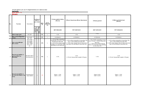
testing per fabric or per colour No. Test item Test method MRL/ GL fabric colour was in AW14 SM list
1.Cotton wadded clothes (Woven)
2.Woven Casual wear (Woven Sportswear)
12.Down garment
13.Skirts and skirted suit (Woven)
garment
fabric
GB/T 2662-2008
FZ/T 81007-2012
MRL MRL MRL GL GL GL GL GL GL
Warp: ≥ -2.0% Weft: ≥ -2.0%
6
Colour fastness to washing /(grade)≥ GB/T 3921 A(1): test temprature: 40℃ GB/T 3921 C(3): test temprature: 60℃ GB/T 12490 A1S: test temprature: 40℃ GB/T 12490 B2S: test temprature: 50℃
GB/T 5711
v
GL
Colour Change: 3-4 Colour Stain: 3-4
Colour Change: 3-4 Colour Stain: 3-4 (lining: no requirement) Colour Change: 3 (only for woven swimming wear, such as beach pants) Colour Change: 4 Colour Stain: 3-4 (only for woven swimming wear, such as beach pants) 3 3 (lining:3-4) 2-3 (lining: no requirement / piled, flocking, dark: 2) Colour Change: 3 Colour Stain: 3 Colour Change: 3 Colour Stain: 3 GB/T 3921 A(1) 4 (lining: no requirement) GB/T 4802.1-2008 ≥3 (except piled fabric) Peached, brushed fabric, worsted fabric: Method E; Loose structure worsted fabric, woolen fabric: Method F; Others: Method D 118N for fabric light weight <150g/sm2; 157N for medium weight 150-250g/sm2; 226N for heavy weight >250g/sm2;
GL船级社关于MED证书的解释

0098-XX
Fig. 1: MED modules
We also discuss with you the most suitable compliance method for your equipment:
1. Non-approved products: Once you have provided us with copies of all test reports, manufacturing plans and supporting documentation for the product and submitted a completed Application Form [/med], we will appraise the documents for compliance with the relevant regulations and designated test standards.
The solution you need
The purpose of the Marine Equipment Directive (MED) is to ensure the free movement of equipment within the EU and guarantee the uniform application of the relevant standards laid down in the international SOLAS, MARPOL and COLREG conventions. A manufacturer only has to gain approval for a certain type of equipment from one Notified Body, and there is no need for the manufacturer and the Notified Body to be located in the same country.
GL风机认证规范中文版

This Guideline was compiled by Germanischer Lloyd WindEnergie GmbH in cooper ation with the Wind Energy Committee. The Wind Energy Committee consists of re presentatives from manufacturers, universities, insurance companies, associations, e ngineering offices, authorities and institutes. The current members of the Wind Ener gy Committee are named on our website: 本指南由德国劳埃德船级社风能股份有限公司在风能委员会的协助下编辑完成。
风能委员会由制造商,大学,保险公司,行业协会,工程部门,权威人士和学院的代表组成。
风能委员会的现有成员在我们的网址:中列出。
This Guideline comes into force on 1st November 2003.本指南于2003年11月1日正式实施。
Interpretation of the Guideline is the exclusive prerogative of Germanischer Lloyd W indEnergie GmbH. Any reference to the application of this Guideline is permitted on ly with the consent of Germanischer Lloyd WindEnergie GmbH.本指南的解释权归德国劳埃德船级社风能股份有限公司。
所有涉及本指南的运用必须得到德国劳埃德船级社风能股份有限公司的同意。
GL船级社关于MED证书的解释
One-stop shopping at GL
Take advantage of GL’s one-stop shopping portfolio! The MED conformity procedure at GL can be ideally combined with other GL services such as type tests, approvals and certifications conducted in accordance with ISO 9001:2008 and/or PED so you can save yourself both time and money. Please take an information tour on our homepage /supplyindustry for more one-stop shopping opportunities.
Germanischer Lloyd AG Department Marine Equipment Directive Brooktorkai 18 · 20457 Hamburg, Germany Phone: +49 40 36149-9929 · Fax: +49 40 36149-7325 med@ · /med
The solution you need
The purpose of the Marine Equipment Directive (MED) is to ensure the free movement of equipment within the EU and guarantee the uniform application of the relevant standards laid down in the international SOLAS, MARPOL and COLREG conventions. A manufacturer only has to gain approval for a certain type of equipment from one Notified Body, and there is no need for the manufacturer and the Notified Body to be located in the same country.
GL认证

图 9. 证书样本
参考文献 1. “Rules for Classification and Construction II Materials and Welding-Non-metallic Materials”, Germanischer Lloyd, Ediition 2006. 2. / 3. Adhesives for bounding wind turbine blades, Reinforced Plastics, 2009, p.26-29 4.
关键词:风力叶片 复合材料 质量管理 测试
引言 国际上, 发展可再生能源正式被很多国家提升为新 能源战略,目前中国是以风能,太阳能,核能为新 能源主要发展思路, 而风能以其成本低,见效快而 在可再生能源中被中国乃至世界发展最为迅速的新 能源。中国政府在能源中长期发展规划中明确提 出:2020 年可再生能源在能源构成中要达到 15% 左右,这也正印证了最新报告中预测“风能将在未 来 12 年内提供世界总能源 12%, 这个比例极有 可能在 2050 年变为 30%”。据不完全推算,每 kW 使用在叶片的复合材料为 10kg,由此可看出复合 材料在风电市场中的巨大潜力,因此复合材料在很 长时期内保持巨大的市场。
6. 油漆(涂料) 风力叶片多在气候恶劣的周围环境下运行,比如紫 外线照射强烈,昼夜温差大,风沙侵蚀严重,沿海
滩涂。因此叶片表面防护用油漆承担着保护作用, 在使用类别上也定为 CM-5 级 参照 ISO12944-2。 另外根据一些国家的法律, 超过一定高度的”建筑” 必须以颜色来起警视作用,因此叶片有时漆成颜色, 如红色. (图 9, 图 10)
德国劳氏集团(GL Group)非金属材料认证中 对风电叶片材料的认证技术规范要求(续)
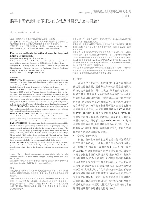
脑卒中患者运动功能评定的方法及其研究进展与问题
aSSb 1671c5926 Cb 21c1470 d e www"#$%&’()*+, ’-.//0123456789)*+,
黄
佳 ! 等 6脑卒中患者运动功能评定的方法及其研究进展与问题
!ቤተ መጻሕፍቲ ባይዱ!
另一类是以运动模式改变为标准的评定体系 , 目 前临床上常采用的有 Brunnstrom 、Bobath 法 、 上田敏法 及 Fugl-Meyer 评 定 法 、MAS 评 定 法 、Rivermead 法 、
O
引言 在脑卒中早期治疗计划的目的在于改善患侧的功
能以及功能的质量 , 故康复工作者应急需掌握的是患 肢的运动功能处在一种什么状态 ,即功能丧失了多少 , 保留了多少 , 其中有多少是正确或是异常的 , 据此才能 知道患者运动障碍的程度 , 指导制定具有针对性的治 疗方案 ,以及观察疗效 , 分析预后等 。 由于运动功能评 定方法种类多 , 为了便于临床科研更加合理地选择相 关运动康复评定法 。 本文应用计算机检索 CSTU 数据 库 1995-01 / 2005-09 和万方数据库 1994-01 / 1995-01 与康复评定相关的文章 , 检索词为 " 康复评定 ", 限定文 章用语为中文 。 同时手工检索 1985-01 / 2002-12 与相 关康复评定的书籍 ,限定书籍语言为中文 , 英文 , 日文 , 检索词为 "脑卒中 、 康复 、 运动功能评定 "。 简要介绍脑 血管意外的运动功能评定方法 。
%&’() *, -./( %6, 3&0 4, 5+& *7680)8/99 ’(: 280;</= +( >./ =/>.0: 0? =0>08 ?&(@>+0(’< /A’<&’>+0( +( 9>80B/ 2’>+/(>97@h(nAA)( Bin/h)+nA C+nA-) #""CD!" E#$FG !#"H#E-.+(’I 黄佳 ! 陈洪沛 ! 郭敏 ! 刘骏 7 脑卒中患 者 运 动 功 能 评 定 的 方 法 及 其 研 究 进 展 与 问 题 J*K7中国临床康复 !#""C!!"E#$IG!#"H# JLLL7M)<@B?7@0=K
软件测试中英文术语对照表

Criterio n)的要求
Bebuggi ng
错误散播
Error Seedi ng
Behavior
行为
组件或系统对输入值的预置条件的反应
Ben chmark Test
基准测试
(1)为使系统或组件能够进行度量和比较而制 定的一种测试标准;(2)用于组件或系统之间 进行的比较,或和(1)中提到的标准进行比较 的测试(与IEEE610—致)
Analysis)、编译(Compilation)、软件产品或应 用文档的使用等。参见Defect、Deviation、
Error、Fault、Failure、Incident、Problem
Arc Test ing
弧测试
Branch Test ing
Attractive ness
吸引力
软件产品吸引用户的能力(ISO9126)。参见
Bespoke Software
定制软件
为特定的用户定制开发的软件。与之对比的是现
货软件(Off-The-Shlf Software)
Best Practice
最佳实践
在界定范围内,帮助提高组织能力的有效方法或 创新实践,通常被同行业组织视为最佳的方法或
实践
Beta Testi ng
Beta测试
用户在开发组织外,没有开发人员参与的情况下 进行的测试,检验软件是否满足客户及业务需 求。这种测试是软件产品获得市场反馈进行验收
Big-Ba ng Test ing
大爆炸测试
非增量集成测试的一种方法,测试的时候将软件 单兀、硬件单兀或者两者同时(而不是阶段性的) 集成到组件或者整个系统中去进行测试(与IEEE
GL认可规范
4.Instruction/Procedure:4.1Range of ApplicationThe present Regulations apply to the approval of manufacturers intending to supply flash butt welded or upset butt welded anchor chain cables in accordance with the Rules for Materials of Germanischer Lloyd (GL), and to the approval of the relevant manufacturing processes. Application of these Regulations to lifting and lashing chains may be agreed upon.Regarding the approval of manufacturers of offshore mooring chains, the GL Rules for Classification and Construction, IV – Offshore Technology, Part 6, Chapter 2, Section 8, apply.4.2Application for ApprovalManufacturers intending to supply chain cables as per 4.1.1 above have to apply for approval with GL in writing. In the application, the envisaged chain cable grades, the corresponding steel grades/material specifications, manufacturing process of them (rolled steels/forgings/cast steels), dimensions and cable supply conditions are to be indicated. Also, it is to be stated whether cables will be manufactured with or without studs.4.3DocumentationThe application for approval is to be accompanied by documentation ona) Organisation structure and quality assurance system.b) Steel grades/material specifications for the envisaged chain cable grades, their chemical composition and mechanical properties.c) Description of bending/assembling facilities: type of furnaces for heating, method of bending and bending temperature, heat treatment facilities, machining equipment.d) Description of welding workshop: equipment, welding procedures, welding process variables, control of welding parameters.e) Studs: material, insertion method, welding procedure.f) Heat treatment: temperature and chain speed for holding times, heating and cooling rates, quenching and cooling medium after tempering.g) Capacity and dimensions of the proof load testing machines. Copies of the last calibration certificate of the proof load testing machines.h) Testing facilities and equipment for the destructive and non-destructive testing and dimension measurement, test personnels qualifications for non-destructive testings. Laboratories for chemical and/or metallographic investigations.i) Names and addresses for initial material (= prematerial) manufacturers where the mill does not produce steel itself. The initial material manufacturers shall be approved by GL, unless their prematerial is used for the manufacture of the products subjected to the approval tests specified in para 4.5.4.4Works InspectionDuring a workshop inspection proof is to be furnished to the GL Surveyor that the facilities required for the proper manufacture and testing of the chain cables are available. The manufacturing processes and the quality assurance system are to be presented and explained to the Surveyor.4.5Approval TestNumber of Test Specimens, Scope of Testing and Further Information to be SubmittedOf each chain cable steel grade, of the largest dimensions two 3- and/or 5-link test specimens each and at least 7 single links are to be presented and subjected to the tests specified below:a)A complete chain cable length (approx. 27.5 m) is first subjected to 5 – 10 % of the proof load on the test bench, and the length is to be measured. Then this chain cable length is subjected to the proof load test.Subsequently the test load is reduced to approx. 10 % and measurements are to be carried out, determining the permanent total elongation, the length over 5 cable links as well as the diameter, outside length and width of 3 links. The elongation must not exceed 5 %. The dimensions must be within the tolerance ranges indicated in the Rules for Materials. The applied load and all measurements are to be reported.After the proof load test the individual links of these specimens must becapable of being moved within an angle of 180° against each other withoutany difficulty.b)Breaking load test on a 3- or 5- links sample of the chain cable length subsequent to the proof load test in a). Breaking load, appearance and location of the rupture are to be reported.c)Bending test (crossweld) 120° on two individual links arranged in horizontal position. In case of larger steel bar diameters a specimen with a semicircle cross sectional area may be machined of the link with the welding in the middle of the specimen. Bending radius: for K1 and K2 3x diameter (or thickness), for K3 5x diameter (or thickness).d)Tensile test on two round test specimens machined out of the link, one of them having the weld seam in the middle, the other without seam; specimen form A or B according to II, Part 1, Chap. 1, Sect. 2.D.1.3.2; declaration of d0 and L0.e)Notch bar impact tests on 2 sets of ISO-V-notch test specimens. One set each (consisting of 3 specimens) is to be placed with its notch on the middle of the welding and into the non-welded side of the link. The notch must be vertical to the original surface of the link. The test temperature is be taken from the Rules for Materials.f)Macro-etching and micrographs in a magnification of 100 : 1, taken from the seam, the transition zone, the base material and the stud imprint: positions 1/4 of the diameter and midthickness.g)Product analysis: The contents of the elements listed in the regulations for the corresponding manufacturing processes (rolled steel/forged products/cast steel) are to be determined.h)Photographs of the tested specimens (tensile and notch bar impact tests, breaking load test and bending test) shall be attached. The dimensions of the specimens and the fracture surfaces must be recognizable. The plots of the registered load-deformation curves obtained for the tensile tests shall be attached, the loading rate shall be declared.Inspections for Quality of WorkmanshipThe cable length as per 5.2 is to be inspected for unobjectionable workmanship, tight fit and proper location of the studs as well as for unobjectionable weldings in the case of welded studs.4.6Test ReportManufacturers will have to compile all test results and photographs of structures in a report, present it to the GL Surveyor for countersignature and forward it to GL. Countersignature shall be amended by personal identification, i.e. personal seal, short sign or name in print.。
test method和testing method
test method和testing method 在软件开发中,"test method" 和 "testing method" 通常是指用于测试软件或系统的特定方法或技术。
这两个术语在某些上下文中可能被视为同义词,但在其他上下文中可能具有微妙的差异。
1.Test Method: 这个术语通常用来指一个具体的测试用例或一组相关的测试用例。
一个测试方法是为了验证软件或系统的一个特定功能或行为而设计的。
它详细说明了如何执行测试,包括输入、预期输出以及用于验证输出是否正确的步骤。
2.Testing Method: 这个术语通常用来描述一种测试策略或技术,而不是一个具体的测试用例。
例如,单元测试、集成测试、系统测试和验收测试都是不同的测试方法。
这些方法的选择取决于要测试的软件或系统的特性以及测试的目标。
简单来说,"test method" 关注的是具体的测试用例,而 "testing method" 关注的是整体的测试策略或技术。
不
过,在实际的软件开发和测试过程中,这两个术语有时可能会互换使用,这取决于上下文和所强调的焦点。
gl施工法

gl施工法GL施工法,全称为Glue Laser Scanning Construction Method,是一种基于激光扫描和三维建模技术的施工方法。
这种方法主要用于建筑、土木工程等领域,通过激光扫描仪对建筑物或结构进行高精度的三维测量,然后利用计算机软件进行数据处理和分析,最后生成精确的三维模型,为施工提供依据。
GL施工法的主要步骤如下:1. 数据采集:使用激光扫描仪对建筑物或结构进行扫描,获取大量的点云数据。
这些数据包括了物体的形状、大小、位置等信息。
2. 数据处理:将采集到的点云数据导入计算机软件中,进行数据处理和分析。
这一步主要包括点云数据的清洗、配准、拟合等操作,以消除误差,提高数据的准确性。
3. 三维建模:根据处理后的点云数据,利用计算机软件进行三维建模。
这一步主要是将点云数据转化为三维模型,形成建筑物或结构的三维视图。
4. 施工方案设计:根据三维模型,设计施工方案。
这一步主要是确定施工的顺序、方法、材料等,以确保施工的顺利进行。
5. 施工实施:按照设计的施工方案,进行施工。
这一步主要是按照三维模型进行施工,确保施工的准确性和质量。
6. 质量控制:在施工过程中,进行质量控制。
这一步主要是通过对比三维模型和实际施工情况,检查施工的准确性和质量,及时发现并解决问题。
GL施工法的优点主要有以下几点:1. 高精度:GL施工法可以提供高精度的三维模型,为施工提供准确的依据。
2. 高效率:GL施工法可以快速完成三维建模和施工方案设计,大大提高了施工效率。
3. 高质量:GL施工法可以通过质量控制,确保施工的准确性和质量。
4. 环保:GL施工法不需要大量的人工和材料,可以减少对环境的影响。
总的来说,GL施工法是一种高效、准确、环保的施工方法,对于提高施工质量和效率,减少资源浪费,保护环境等方面都有重要的作用。
r语言glht函数
r语言glht函数R语言是一种功能强大的统计编程语言,它具有丰富的统计数据分析工具和可视化功能。
其中,glht函数是R语言中很常用的一种多重比较检验方法。
glht函数是multcomp软件包中的函数,它的全称是“general linear hypothesis test”。
该函数的作用是进行多重比较检验,也就是通过对不同的组别进行比较,来确定它们是否存在显著的差异。
glht函数可以对各种类型的统计模型进行多重比较的测试,如线性回归模型、广义线性模型等。
glht函数的语法结构为:glht(model,linfct,alternative,p_adjust.method)其中model表示待检验的模型,linfct表示需要进行的多重比较的假设,alternative表示假设检验中备选的假设类型,p_adjust.method是多重比较校正方法。
linfct是glht函数中最为关键的参数。
它决定了多重比较的假设,可以输入不同的线性变换来构建各种假设类型。
根据linfct不同的选择,可以进行多种类型的多重比较检验,如平均组间比较、多重比较中的所有成对比较、一些特定对的成对比较等。
使用glht函数进行多重比较检验的步骤如下:步骤1:安装multcomp包。
使用如下代码:install.packages("multcomp")步骤2:载入multcomp包。
使用如下代码:library(multcomp)步骤3:调用glht函数。
例如进行一组数据的t检验:data<-c(1,2,3)model<-lm(data~1)t.test(data)summary(glht(model,linfct=mcp(estimate="mean"),alternative= "greater"))总之,glht函数是一种简便、灵活的进行多重比较检验的方法。
gllc检查的详细流程

gllc检查的详细流程GLLC检查的详细流程GLLC(Generalized Likelihood Ratio test for Linearity Check)是一种用于检查时间序列数据线性性的统计方法。
它可以通过对时间序列的数据进行统计检验,评估数据是否满足线性模型的假设。
本文将详细介绍GLLC 检查的流程,并逐步回答相关问题。
第一步:收集数据收集与研究目的相关的时间序列数据。
时间序列数据是按时间顺序排列的观测值,可以包含一维或多维数据。
第二步:预处理数据对收集到的时间序列数据进行预处理,以确保数据的质量和准确性。
预处理过程可能涉及对缺失数据进行填充、数据平滑、异常值检测和去除等步骤。
预处理后的数据应该符合时间序列分析的基本要求。
第三步:检查数据的平稳性GLLC检查是基于假设时间序列数据是平稳的。
因此,在进行GLLC检查之前,需要首先检验数据的平稳性。
常用的平稳性检验方法包括ADF (Augmented Dickey-Fuller)检验和KPSS(Kwiatkowski-Phillips-Schmidt-Shin)检验。
如果数据不满足平稳性的要求,则需要进行平稳性处理,例如差分运算。
第四步:确定线性模型GLLC检查是基于时间序列数据是否满足线性模型的假设进行的。
因此,在进行GLLC检查之前,需要确定一个适当的线性模型。
线性模型可以用来描述数据的趋势和相关性。
常用的线性模型包括线性回归模型和ARMA (AutoRegressive Moving Average)模型。
第五步:计算似然比统计量GLLC检查的核心是计算似然比统计量。
似然比统计量是用来比较具有不同假设的两个模型的拟合优度的。
在GLLC检查中,我们比较线性模型和非线性模型(例如非线性回归模型或非线性ARMA模型)的拟合优度。
第六步:设定显著性水平在进行似然比检验之前,需要先设定显著性水平。
显著性水平是一个统计判断的标准,用来评估某个结果是否足够偏离假设。
CNAS-GL27:2009《声明检测或校准结果及与规范符合性的指南》

CNAS-GL27声明检测或校准结果及与规范符合性的指南GUIDLINES ON STATING TEST OR CALIBRATION RESULTS AND COMPLIANCE WITH SPECIFICATION中国合格评定国家认可委员会声明检测或校准结果及与规范符合性的指南1 目的与范围1.1 本文件旨在为实验室声明检测或校准结果及与规范符合性的方法提供指南。
1.2 本文件等同采用APLAC TC004《检测和校准结果及与规范要求符合性的声明方法》(第三版)(Method of Stating Test and Calibration Results and Compliance with Specification)。
1.3 本文件为指导性文件,供检测或校准实验室参考使用。
2 引用文件2.1 CNAS-CL01:2006《检测和校准实验室能力认可准则》(等同采用ISO/IEC17025:2005)2.2 VIM,国际通用计量学基本术语,由国际计量局(BIPM)、国际电工委员会(IEC)、国际临床化学和实验医学联合会(IFCC)、国际标准化组织(ISO)、国际理论化学和应用化学联合会(IUPAC)、国际理论物理和应用物理联合会(IUPAP)和国际法制计量组织(OIML)发布2.3 JJF1059《测量不确定度评定与表示》3 术语和定义本文件引用VIM和JJF1059中的术语和定义。
4 声明检测或校准结果及与规定限值符合性的方法4.1 一般方式4.1.1 检测或校准结果及其不确定度报告内容应当根据客户和规范的要求及结果的用途而定。
检测或校准报告或记录中应包含结果的计算方法,适用时,还应包括计算不确定度的方法。
其内容包括:— 数据分析中的步骤和计算应当形成详尽的文件,以确保必要时可重复计算;— 分析中所进行的所有修正和所使用的常数及其来源;— 有详尽的文件说明不确定度的计算过程。
4.1.2 报告检测或校准结果及其不确定度时,应当避免使用过多的有效数字位数。
GL的职责12539;职务
水平 3
水平 4
T : 训练中 P : 计划中3~4 2~4
水平 TL-1 TL-2 TM-1 TM-2 TM-3 TM-4 TM-5 TM-6 TM-7 TM-8 TM-9TM-10TM-11TM-12TM-13 合计
工程
24
#1
P
043 4
#2
363 9
#3
083 8
#4
073 7
#5
T2 6 3 8
备齐了规定数量的正确部品、工具吗?
④ 4S文化的落实
4S=公司的文化
GL的工作: 4S的指示、文化的落实
职场的4S水平
安全水平 品质水平 人员水平
④ 4S文化的落实
对4S的理解水平
①4S=扫除 ②4S=整理、整顿、清扫、清洁 这4个词 ③4S= 4个词和它的意思 ④4S=看得到物品的异常 ⑤4S=异常⇒改善(4S是改善的工具)
人员配置板
生产班组:
GL
GL TL 2
12
10
8
TL
TL
2
1
后工程
后总装线
缺勤
TM TM
1
5
11
9
7
培训
TM 12
6
4
2
TM
13
TM
TM
6
2
5
3
1
前工程 TL 1
新人工程
特殊岗位 (需要特殊资格)
新人
具备特殊资格的人
实习工
支援者
1班
GL TL TL 1
2345
TM TM 34
6 7 8 9 10 11 12 13 14 他组过来的
Level1
热轧带肋钢筋拉伸试验能力验证技术方案
热轧带肋钢筋拉伸试验能力验证技术方案2011年第l期昆钢科技KungangKe]i2011年1月热轧带肋钢筋拉伸试验能力验证技术方案高志方林辉赵冰(技术中心)摘要本~vX2010年云南省钢材拉伸试验能力验证项目为实例,阐述了采用热轧带肋钢筋样品进行拉伸试验能力验证的样品策划,制备,均匀性检验及筛选技术,以及结果的统计分析方法策划和运用技术,并分析说明了检测结果的统计处理情况和存在的系统偏差.关键词能力验证热轧带肋钢筋拉伸试验均匀性检验稳健统计技术TechniqueProgramofProficiencyTesting forHotRolledRibbedBarsTensileTestGaoZhi——fangLinHuiZhaoBing(TechnologyCenterofKISCO)AbstractInthispaper,aproficiencytestingprogramforsteeltensiletestofYunnanpro vincialin2010wasintroduced.Thisproficiencytestingforhotrolledribbedbarstensiletestwasdescribed,includingthechoiceofexperimentalsample,preparationofsamples,homogeneitycheck,thetechnolog yofsamplesscreening,and theselectionandapplicationofstatisticalmethod.Generalresulsofstatisticaltreatm entandsystematicbiasoftestresultswereexplainedaswel1.Keywordsproficiencytesting;hot-rolledfibbedsteelbars;tensiletest;homogeneity check;robuststatisticaltechniques1前言能力验证是利用实验室间比对来确定实验室的校准,检测能力或检查机构的检测能力.钢材拉伸试验是各综合质检机构,工程材料检验实验室及钢材生产企业实验室的常规检测项目,各实验室的检测能力受设备,人员和方法等多种因素影响,存在差异性.借助能力验证来识别和分析这些差异性,以提高实验室的检测能力,是实验室及其管理机构所使用的主要技术手段之一.钢材拉伸试样能力验证受到样品制备的制约(受样品均匀性,外形尺寸,热处理及加工等因素制约1,大规模组织具有一定的难度.结合钢铁企业生产条件,采用常规热轧带肋钢筋作为能力验证样品,为大规模地组织开展钢材拉伸试验能力验证活动提供了便利条件.热轧带肋钢筋拉伸试验能力验证方案的技术关键和要求在于策划和制备均匀的拉伸样品以及采用有效的结果统计分析方法,以保证能力验证系统正确评价结果的能力.2010年云南省钢材拉伸试验能力验证采用热轧带肋钢筋测试样品,参加实验室涵盖了省质量技术监督局依法设立的省,市及地州检测中心,依法授权的各质检站,各级建设工程质检机构以及省内各钢铁生产企业的实验室共208家,本文以此案为实例, 重点研究和阐述热轧带肋钢筋拉伸试验能力验证的样品策划,制备,均匀性检验和筛选技术,以及结果的统计分析方法策划和运用技术,并分析说明了昆钢科技2011年第l期检测结果的统计处理情况和存在的系统偏差,为相关机构和人员开展此项工作提供参考.2测试项目及样品策划钢筋拉伸试验能力验证采用的样品及测试项目应尽可能反映实验室常规的检测指标,尺寸规格,并能反映不同量程下拉伸负荷的一致性或变异.因此,策划开展的钢筋拉伸测试指标为抗拉强度(Rm), 下屈服强度(ReL),断后伸长率(A)三个常规指标.考虑到这三个指标的属性及相关性,设定下屈服强度(ReL)和抗拉强度(Rm)为能力验证的关键指标.为能识别实验室间的变异和实验室内的变异,策划采用分割样品对方案——采用12mm和14mm规格的同牌号HRB335钢筋,其Rm,ReL,A结果差异不大,但两种规格的屈服负荷和抗拉负荷都分别有20%一30%的差异.拉伸试验结果的精密度受到多方面因素的影响,引起测量不确定度的主要因素包括材料的不均匀度,试样的几何形状和公差,夹持方法和施力的轴向性,拉伸试验机和辅助测量系统(刚性,驱动,控制,操作方法),试验的各阶段中的试验温度和加载速率,人为的或与拉伸性能测定相关联的软件误差等.参考GB/T228—2002《金属材料室温拉伸试验方法》附录K中方案C给出的Q235圆钢不确定度评定结果,综合考虑样品的特性,实验室内的重复性,试验方法的复现性及实验室间的变动性,各实验室热轧带肋钢筋抗拉强度测试结果的标准偏差(或标准IQR)估计在均值的-t-3%,下屈服强度测试结果的标准偏差(或标准IQR)估计在均值的.4-5%,断后伸长率测试结果的标准偏差(或标准IQR)估计在均值的±10%.因此,样品各特性值的分散程度(标准偏差)按上述预期值的三分之一来设计和控制.CNAS—GL03《能力验证样品均匀性和稳定性评价指南》(以下简称《指南》)给出了能力验证样品的均匀性和稳定性检验方法.钢筋样品力学性能的稳定性较好,因此可不进行稳定性检验,只考虑均匀性检验.《指南》给出的均匀性检验方法对可重复检测的非破环试样较为适用,但本案样品的测试是破环性试验,样品需规模生产,不能简单使用《指南》的均匀性检验方法,需从样品生产,取样,试验,筛选等诸环节进行设计和控制,并返复使用《指南》中列出的单因子方差分析方法进行均匀性检验,直至筛选出的样品通过检验为止.具体方案如下:1)跟踪控制钢材的冶炼,保证钢坯成分的均匀性;2)在轧钢工序挑选成分适宜的两三个炉批,控制轧制,尽可能保证钢筋性能和外形尺寸均匀;31从同一根钢坯的钢筋上抽取一组钢筋(每根定尺长度为9m或12ITI)作为候选样坯,并按策划抽两种规格;4)将每根样坯上截取的拉伸试验样品作为一组子样,共r组(按参加实验室的数量,准备两倍以上数量的样品候选);5)从每组子样中抽取样坯头尾附近的两件样品进行均匀性试验;6)将m组的共rX2件子样全部进行均匀性试验,然后对测试结果进行单因子方差分析,剔除结果偏离的子样,直至通过均匀性检验,剩余的子样组则是符合均匀性要求的样品.本案策划采用武钢集团昆明钢铁股份有限公司生产的12mm和14mm规格HRB335热轧带肋钢筋为样批,各规格样坯分别取自同一根钢坯轧制的钢筋,先按生产条件截成数十根9m定尺长度,顺序编号.每根9m钢筋再截成1.8m长的5段,每段顺序编号,每段上截取350mm长的拉伸试样5件.将每根样坯截取的样品作为一个子样组,12mm钢筋共有28 组,14mm钢筋共有20组,然后在每根钢筋的第2和第4段部位上各取一件样品做均匀性试验.3样品均匀性检验为保证钢筋性能的稳定性,先将室温样品放置一周后再进行均匀性试验.拉伸试验采用600kN液压万能试验机,由同一技术熟练人员在室温条件下2011年第l期高志方,林辉,赵冰:热轧带肋钢筋拉伸试验能力验证技术方案操作试验机,依据GB/T228—2002《金属材料室温拉伸试验方法》标准要求,按13常操作习惯控制各阶段拉伸速度,并在短时间内完成一种规格的全部样品拉伸试验.采用Minitab15软件进行单因子方差分析,通常显着水平取0.05,如检验结果的F值<F临界值=F.『n1.n2),或P<,则表明样品是均匀的,通过检验.本案12mm钢筋初始样品共28组56件,其抗拉强度(R)均匀性试验初次分析结果如表1所示:表1巾12mm钢筋抗拉强度(R)均匀性试验结果单因子方差分析表Table1ANOVAResultsof12ramsteeltensilestrength(Rm)表1中F=1.26<F临界值=Fo.95(27,2s)=1.89(查F分布的0.95分为数值F.『27,无对应值时采用内插法计算),表明样品抗拉强度结果组内和组间没有明显差异,样品是均匀的,检验通过.下屈服强度和断后伸长率的单因子方差分析结果与表1雷同,三项指标初步分析汇总结果见表2所示:表212mm钢筋拉伸匀性试验结果初次单因子方差分析汇总表Table2FirstANOVAResultsof击12ramSteelTensileTestR,RA三项指标具有相关性,应全部通过检验.表2显示,初次方差分析中RA未通过均匀性检验.剔除结果偏离较大的子样组,对剩余的18组36件子样再次进行单因子方差分析,汇总结果见表3所示:表312mm钢筋拉伸匀性试验筛选结果单因子方差分析汇总表Table3ANOVAResultsof小12ramSteelTensileTestafterScreening 表3显示,Rm,R乩,A三项指标的F值都小于F临界值=F095fI7-l81=2.24(查F分布的0.95分为数FnI95(17,l8),无对应值时采用内插法计算),说明筛选后的18组样品满足均匀性要求.另外,表3显示,Rm,R乩,AZ项指标的标准偏差都在策划范围内,均小于参加实验室测试结果估计标准偏差的1/3,表明样品的分散程度满足能力验证要求.为此,我们认为这18组样品达到策划目标要求,可以发放各参加实验室进行测试.对14mm钢筋采用同样的均匀性检验和筛选步骤,剔除4组样品,最终筛选的16组样品均匀性和分散性满足策划要求,可以发放各参加实验室进行测试.这16组32件子样均匀性试验结果单因子方差分析汇数据总见表4所示,其中F临界值=F.fl5..1=2.35(查F分布的0.95分为数F.f15l1),满足F<F临界值=Fo95『l5_161的检验条件:.40?昆钢科技2011年第1期4能力验证结果的统计分析及评价方法依据CNAS—GL02《能力验证结果的统计处理和能力评价指南》,检测结果可采用四分位稳健(Robust)统计技术处理,采用参加实验室获得的公议值——中位值(m)来估计样本总体的均值,采用标准四分位内距(SIQR)来度量样本数据的分散程度(四分位点内距IQR乘以因子0.7413得到标准四分位点内距,相当于正态分布的标准差),以减少极端结果对平均值和标准偏差的影响.分别计算各实验室三对拉伸试验结果的实验室间z比分数(ZB)和实验室内z比分数(ZW),分别用于衡量某实验室结果对的标准化和与标准化差与相应中位值的偏离程度,并以ZB和ZW评价每个参加实验室的检测结果:IZI≤2,为满意结果(约有95%的数据,分布在Ill一2?SIQR—m+2?sIQR范围内)2<1Z[<3,为可疑结果(约有4%的数据,分布在m一3'SIoR—I13—2.SIQR和m+2?SfQR~m+3?SIQR范围内)IZI≥3,为不满意或离群结果(约有不到1%的数据,分布在≤m一3?sIQR和≥m+3?SIQR范围内)一般情况下,ZB出现离群值或可疑值的实验室,是由于两个样品的测定结果与中位值比较均偏低或偏高,说明测量过程中存在系统偏差;ZW出现离群值或可疑值的实验室,是由于两个样品的测定结果一个偏低,一个偏高所致,说明存在实验室内的偏差.为避免实验室极端异常值对公议值的过度影响以及对系统灵敏度的影响,避免统计系统的判断能力不足或发生偏差,应剔除极端异常值.先采用四分位数稳健统计方法(Robust)计算ZB和ZW,找出R乩,R中ZB或ZW的绝对值大于等于5的极端异常值(数据服从正态分布时出现的概率小于百万分之一),并通过专家判断异常后,一并剔除这些出现极端异常值的数据组及实验室.之后,再次采用四分位数稳健统计方法(Robust),对剩余数据组计算各性能指标的zB和ZW,并作为最终评价值.对剔除极端异常值后的数据对,还采用尤登(Youden)图表示出实验室结果对的分布位置,以便直观地识别和分析实验室数据对的偏离倾向和程度.这些图对结果的双变量分析有约95%置信椭圆的特性,并用虚线来标明每个样品的中位值.这个椭圆是通过在双变量z比分数空间中,标定一个约95%的置信区间(为圆)转换回原始数据空间来估算的.Youden图中椭圆以外的点,大体相当于那些z比分数大于2或小于一2的值.5能力验证结果和分析本案共有208家实验室参加和提交了拉伸试验数据,其中五家实验室出现一件拉伸试样断偏,实验室判定结果无效而未报出断后伸长率,一家实验室较晚报出测试结果而未纳入统计.利用Excel对208家实验室的3对数据进行初步统计分析,其中R或R乩出现IZBI或IZWI≥5的极端异常结果实验室有26 家,剔除这26家实验室的三对异常值后再进行最终统计分析,所有结果中出现IZBI或fZWI≥3N群数据的实验室29家,无离群但出现可疑数据(2<IZBI<3或2<IZWI<3)的实验室47家,其余106家实验室的结果全部满意(IZBI和IZBI≤2),占全部实验室的51%.以下阐述关键指标抗拉强度(R)和下屈服强度(R乩)的统计分析结果.2011年第1期高志方,林辉,赵冰:热轧带肋钢筋拉伸试验能力验证技术方案12mm和14mm钢筋样本的R测试结果初次(全部实验室)和二次(剔除极端异常值后实验室)统计量汇总如表5所示:表5R初次和二次统计量汇总对照表Table5PrimaryandSecondaryStatisticsSummaryTableforRm样本数207207181181中位值561.4543.2560.0541.9SIQR8.5211.497.568.52稳健CV0.015O.0210.014O.016最小值407.7487.3517.2510.1最大值704.5643.2612.3579.5范围2968155.995.169.4表5统计结果与表3,表4样品均匀性试验结果比较显示:1)R二次统计结果较初次结果中位值偏低,接近样本均匀性试验均值,统计一致(通过双正态均值检验,显着性水平取0.01);R二次统计结果的离散程度降低,尤其中14mm样品s.降i~T26%,提高了统计系统的分辨率.2)R二次统计结果的SoR均小于10MPa,稳健cV小于0.02,低于3%的可接受目标,满足预期要求.中12mm和14mm钢筋样本的R乩测试结果初次(全部实验室)和二次(剔除极端异常值后实验室)统计量汇总如表6所示:表6F:I.初次和二次统计量汇总对照表Table6PrimaryandSecondaryStatisticsSummaryTableforRL 样本数207中位值381.0SIQR17.12稳健cV0.045最小值260.0最大值517.2范围257.2表6统计结果与表3,表4,表5样品均匀性试验结果比较显示:1)R二次统计结果较初次结果中位值变化不大;R二次统计结果的离散程度降低,SIQR降低了约25%,提高了统计系统的分辨率;R的实测中位值与样本均匀性试验均值不一致(通不过双正态均值检验,显着性水平取0.01),存在系统性偏高.2)R.L二次统计结果的soR~d'T15MPa,稳健cvd,于0.04,低于5%的可接受目标,满足预期要求.3)R的离散程度明显大于R,且都远大于均匀性试验结果的离散,存在离群数据.为证实R乩测量结果存在系统性偏高,采用专家法选定省,市,地州,企业和质检机构中技术能力可信度相对较高的30家实验室为样本实验室,统计分析其测试结果,全部实验室和样本实验室测试结果统计量对照如表7所示.表7R测定统计量对照表Table7StatisticsSummaryTableforR各实验室R测试结果样本实验室R测试结果(二次统计)(N/n1In)统计值一组样本二组样本一组样本二组样本12mm中14rI1n1中12nL~14n1m表7统计结果显示,各实验室两组样本下屈服强度的实测中位值与样本实验室的中位值仍然不一致(通不过双正态均值检验,显着性水平d取0.01),存在系统性偏高.剔除出现极端异常结果实验室后,测试结果的分布范围依然是样本实验室的2—3 倍.可以判断,各实验室在测量R乩时存在系统偏差,且分散较大,应加强控制,尤其注意控制测量设备,软件,加载速度和读数的控制.R和R擞据对分布~Youden图1和图2所示,R詈鲁旧侣叭叩233O555C;m髓¨加"?42?昆钢科技2011年第1期和ReL都沿左下象限和右上象限呈椭圆分布,且游离在95%的椭圆置信区间以外的数据对(标出实验室代码)多数分布在远离椭圆中心的左下象限或右上象限,说明这些数据呈现系统性偏小或偏大.少数数576.5566.5556.5籁546.5536.5526.5516.5506.5433.1413.1373.1353.1333.1据对处于椭圆外的左上或右下象限,说明一个样品的结果过高,而另一个过低,存在较大的实验室内随机误差.图1RmYouden图Figure1YoudenChartforRm512.2532.2552.2一组数据572.2图2ReLYouden图Figure2YoudenChartforReL592.2612.2330,2350.2370.2390.2410.2430.2450.2一组数据(下转第47页)孵2011年第1期徐晋,朵勇,杨宝珍:转炉化渣剂x一荧光光谱分析法的试验研5结论1)采用x一射线荧光光谱法测定炼钢化渣剂,应严格控制试样粒度,特别是试样中的金属颗粒.2)本方法能解决传统化学分析方法测定炼钢化渣剂的分析周期长的问题,能够满足炼钢快节奏生产的需要,具有一定的经济效益.3)本方法的使用提高了大型精密分析仪器的设备利用率,降低了分析成本.4)通过采用x一射线荧光光谱法测定炼钢原辅料化渣剂可以消除由于化学分析带来的废气和废液污染物的排放,避免了对环境的污染,达到节能减排的目的.参考文献:[1]理学电机工业株式会社应用研究中心等.x射线荧光分析原理与应用,1997[2]化验员分析读本.刘珍主编[3]鞍钢钢铁研究所等.实用冶金分析.辽宁科技出版社,1990(上接第42页)6结论1)采用热轧带肋钢筋不同规格分割样品对作为能力验证样品是可行的选择方案,通过样品的生产控制,按样坯分组进行均匀性试验和单因子方差分析,筛选,可以保证样品均匀性要求,既样品均匀性试验结果标准偏差控制在能力验证实际测试结果估计标准偏差的1/3以内.2)分次采用四分位数稳健统计方法(Robust),并借助专家判断,剔除极端异常值后再统计,可以减少极端异常值对中位值(公议值)及结果分散程度的影响,使得统计分析和结果判定更符合客观实际.3)云南省208家实验室钢筋拉伸试验的主要问题是,大约25%的实验室R和R测试结果存在系统偏差(偏大或偏小),R测试结果分散程度较大,且存在系统性偏高现象.本案中凭借经验和总体分析判断,一次统计剔除出RR中zB或ZW的绝对值大于等于5的极端异常值,剔除是否充分的问题需要进一步论证和探讨.另外,本案中采用参加实验室的公议值为能力验证样品的指定值,各实验室R结果与样本实验室结果存在不一致性,是否应采用专家实验室(样本实验室)的公议值为能力验证样品的指定值,还是应对获得的指定值进行修正,也值得进一步研究探讨参考文献:【1]中国合格评定国家认可委员会.CNAS—GL03能力验证样品均匀性和稳定性评价指南iS].2006,06【2】中国合格评定国家认可委员会.CNAS—GL02能力验证结果的统计处理和能力评价指南[s].2006,06[3]马林,何桢.六西格玛管理[M].北京:中国人民大学出版社,2007THANKS !!!致力为企业和个人提供合同协议,策划案计划书,学习课件等等打造全网一站式需求欢迎您的下载,资料仅供参考,如有侵权联系删除!。
6高程测量方法
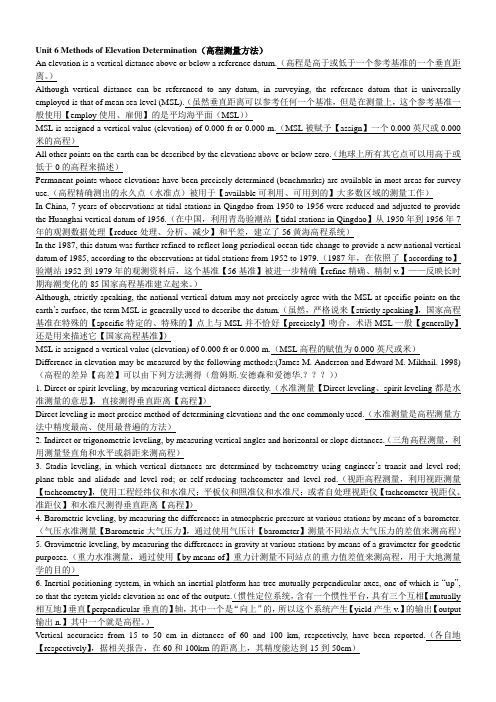
Unit 6 Methods of Elevation Determination(高程测量方法)An elevation is a vertical distance above or below a reference datum.(高程是高于或低于一个参考基准的一个垂直距离。
)Although vertical distance can be referenced to any datum, in surveying, the reference datum that is universally employed is that of mean sea level (MSL).(虽然垂直距离可以参考任何一个基准,但是在测量上,这个参考基准一般使用【employ使用、雇佣】的是平均海平面(MSL))MSL is assigned a vertical value (elevation) of 0.000 ft or 0.000 m.(MSL被赋予【assign】一个0.000英尺或0.000米的高程)All other points on the earth can be described by the elevations above or below zero.(地球上所有其它点可以用高于或低于0的高程来描述)Permanent points whose elevations have been precisely determined (benchmarks) are available in most areas for survey use.(高程精确测出的永久点(水准点)被用于【available可利用、可用到的】大多数区域的测量工作)In China, 7 years of observations at tidal stations in Qingdao from 1950 to 1956 were reduced and adjusted to provide the Huanghai vertical datum of 1956.(在中国,利用青岛验潮站【tidal stations in Qingdao】从1950年到1956年7年的观测数据处理【reduce处理、分析、减少】和平差,建立了56黄海高程系统)In the 1987, this datum was further refined to reflect long periodical ocean tide change to provide a new national vertical datum of 1985, according to the observations at tidal stations from 1952 to 1979.(1987年,在依照了【according to】验潮站1952到1979年的观测资料后,这个基准【56基准】被进一步精确【refine精确、精制v.】——反映长时期海潮变化的85国家高程基准建立起来。
双缩脲法测定血清总蛋白的方法学评价

双缩脲法测定血清总蛋白的方法学评价吴文钦(广东医学院医学检验学院广东-东莞 523808)摘要:目的对双缩尿法测定血清总蛋白进行方法性能评价,达到提高分析方法质量的目的。
方法配制双缩脲试剂,并用所配制的双缩脲试剂与标准血清总蛋白进行批内重复性试验、回收试验以及线性范围评价试验,从而评价双缩尿法测定血清总蛋白的精密度、准确度和线性范围。
结果用分光光度计测定波540nm 处的吸光度A,进行相关数据分析,双缩脲法测定血清总蛋白的批内重复性试验的变异系数 CV%为2.36%,回收试验平均回收率为105%,线性范围评价试验R2为0.9980。
结论在严格规范操作下,双缩脲法测定血清总蛋白的精密度高,准确度以及线性范围较好,满足临床对血清总蛋白定量测定要求,是临床测定血清总蛋白的常规方法。
关键词:双缩脲法;血清总蛋白;方法学评价Biuret method was developed for the determination of protein evaluation methodologyAbstract Objective The purpose of the double reduction of urine protein determination of serum total performance evaluation methods, to improve the quality of analytical methods.Methods Biuret test preparation, and formulated with the biuret test standard serum total protein in the assay reproducibility test, recovery test and linear range of evaluation test to evaluate the double reduction of urine assay precision of serum total protein, accuracy and linear range.Results A spectrophotometer absorbance at 540nm wave, the associated data analysis, determination of intra-assay coefficient of variation of total serum protein test reproducibility CV% was 2.36%, the average recovery recovery test 105% biuret method, linear evaluation test range R2 is 0.9980.Conclusion In the strictly regulate the operation, biuret serum total protein, high precision, accuracy and linearity better meet the clinical requirements for quantitative determination of total serum protein, serum total protein conventional methods of clinical measurement.Key words Biuret method; Total serum protein; Evaluation Methodology为满足临床医疗对实验室检验的不断要求,实验室需要不断引进新方法或者改进原有的方法。
- 1、下载文档前请自行甄别文档内容的完整性,平台不提供额外的编辑、内容补充、找答案等附加服务。
- 2、"仅部分预览"的文档,不可在线预览部分如存在完整性等问题,可反馈申请退款(可完整预览的文档不适用该条件!)。
- 3、如文档侵犯您的权益,请联系客服反馈,我们会尽快为您处理(人工客服工作时间:9:00-18:30)。
II-Part3 GL2000Section5Mechanical and Technological Tests Chapter2Page5–1 BSection5Mechanical and Technological TestsPreliminary remarks:This section has,for the time being,still been retained in its earlier form despite the fact that more up-to-date EN and ISO standards have since been either issued or are available in draft form relating to the key de-structive tests carried out on welded joints in metallic materials.The intention is to delete this section alto-gether at a later date and instead to make reference only to the new standards in Chapter1,Section4, "Welding Procedure Tests"(where the information relating to the mechanical and technological tests is chiefly needed).These standards include:–EN895/ISO4136Transverse tensile test(replacement for DIN50120-1and50120-2)–EN876/ISO5178Longitudinal tensile testing of the weld metal infusion welded joints–EN910/(ISO5173)Bend tests(replacement for DIN50121-1and50121-2)–EN875/ISO9016Notched bar impact test(replacmenet forDIN50122)–EN1043/ISO9015Hardness test,miscellaneous parts(Replacement for DIN50163)–EN1320/ISO9017Fracture tests(replacement for DIN50127)–EN1321Macroscopic and microscopic examinations–EN ISO8249Determination of ferrite numberThe mechanical and technological tests shall,wherever possible,be performed in accordance with the new standards.For an interim period,or where the new standards are not yet available,the mechanical and technological tests may continue to be performed in accordance with the following provisions,but also in compliance with the information given in Chapter3. The test records shall state which rules were used as a basis for the test.Where the provisions given in the various rules differ widely,the procedure shall be agreed with the Society.A.Scope1.These Rules relate to the normal methods and forms of test specimens to be used in the mechanical and technological testing of welds,e.g.of test pieces for the welding procedure and workmanship tests,as well as to the metallographic inspections necessary for this purpose.2.Special methods and forms of test specimens(e.g.for testing the manual skill of welders or testing of welding consumables,auxiliary materials and over-weldable shop primers)are specified in the relevant sections.3.The test methods and forms of specimens indicated in the standards mentioned in the following paragraphs shall be used wherever possible.Methods and forms of specimens conforming to other standards may be used by agreement with the Surveyor,pro-vided that the same results can be achieved.B.Preparation of Specimens and Testing1.All tests are to be performed by trained per-sonnel using calibrated testing machines.The testing machines must be kept in good working order by their owners and are to be calibrated at regular intervals by an independent inspecting authority.2.Before being cut out of the test piece,speci-mens are to be marked by the Surveyor.They shall then be cut out,wherever possible by a mechanical process,and machined to the required dimensions. Where specimens are cut from the test piece by a thermal process,they must be wide enough to ensure that the heat-affected zone can be completely ma-chined off.3.All mechanical and technological tests are to be performed in the presence of the Surveyor,unless otherwise stipulated or agreed.The photographs of metallographic specimens are to be submitted to him for evaluation.Chapter2 Page5–2Section5Mechanical and Technological Tests II-Part3GL2000 CC.Tensile Tests1.Tensile tests on flat tensile specimens(DIN50120,Part1)1.1This test is carried out to determine the ten-sile strength,position,type of fracture and,where appropriate,the elongation of specimens located at right angles to the seam.The flat tensile specimen shown in Fig.5.1should be used wherever possible. 1.2The thickness'a'of the specimen is normally the wall thickness.If this is greater than30mm but less than50mm,the specimens may be machined down on one side to a thickness of30mm.With thicknesses of50mm and over,two or more speci-mens regularly spaced over the section are to be pre-pared.Specimenthickness a£ 5> 5to£ 10> 10to£ 20> 20to£ 30Specimen width b Gauge length L cHead width B Total length L t Radius at shoulder r15202530Weld widthb s + 80 mm 1³ 25³ 30³ 35³ 40³ 35³ L c + 1801bs measured on the side of the weld the greaterseam width.Fig.5.1Flat tensile specimen(welded joint)1.3Welded joints in aluminium alloys shall be tested using a tensile specimen conforming to DIN50123.2.Tensile test on round tensile specimens(EN10002/DIN50125)2.1This test is carried out to determine the ten-sile strength,yield strength or0,2%proof stress,re-duction in area and elongation of the weld metal. Where necessary in the case of high-temperature steels,the0,2%proof stress at elevated temperatures shall also be established.Wherever possible,the test should be performed on a10mm diameter round ten-sile specimen of the type depicted in Fig.5.2,which is to be cut out of theweld metal with its longitudinal axis in the direction of the seam.2.2If,in exceptional cases,the weld dimensions do not permit the preparation of a10mm diameter tensile specimen,specimens with a smaller diameter may be used,provided that the gauge length is5times and the parallel length at least6times the diameter of the specimen.3.Tensile tests on cruciform tensile speci-mens3.1This test is carried out to determine the ten-sile shear strength Z S of the weld metal.Three speci-mens with the dimensions shown in Fig.5.4shall be tested in each test.GL 2000Page 5–3Fig. 5.4Cruciform tensile specimens3.2The tensile shear strength Z S is to be deter-mined by the following formula (cf. Fig. 5.5):a a tion S a a fracture tion S 12341234+=+=fracture sec sec Tensile shear strength Z S :=S BFig.D.Bend Tests1.Transverse bend test (DIN 50121, Part 1)1.1This test is carried out to determine the duc-tility of the welded joint across the seam. For this purpose the specimen is bent over a mandrel or pre-scribed diameter and the angle achieved and, if speci-fied,the bending elongation on the tension side of the specimen are measured.Specimens to Fig. 5.6 are to be prepared for the test.Section A - BDimensionsSpecimen width bSpecimen length L t 1 whereRadius r, side in tension1 If the specimen lengths L tcannot be met, the minimum specimen lengths shown in Table 6 of DIN 50 121, Part 1 apply.Specimen thickness ad __a £ 3> 27 £ 35³ 1,5 a 300430530£ 3d __a = 4d __a = 6£ 1120250250250£ 2> 11 £ 1430250250250£ 2> 14 £ 1730250250290£ 2> 17 £ 22³ 1,5 a 250290350£ 3> 22 £ 27³ 1,5 a 300350430£ 3Fig. 5.6 Specimen for transverse bend testPage5–4GL20001.2The thickness of the specimen is normally the wall thickness.If this is greater than30mm,the specimens may be machined down on one side to a thickness of30mm.On the side of the specimen which is in tension during the test,the edges may be rounded to the specified radius r.1.3Depending on the test specification,the specimens are to be mounted in the testing device in such a way that either the upper or the lower side of the weld is in tension during the test.The test rig is to be set up as shown in Fig.5.7.1.4If the bending elongation is to be deter-mined,the deformation zone on the tension side of the specimen shall be provided prior to the test with gauge marks set5mm apart and these shall be used to measure the elongation when the prescribed bending angle has been reached.The gauge length L0is the weld width plus the wall thickness.Fig.5.7Test rig1.5If the elongation behaviour of the base mate-rial and the weld metal differ greatly,e.g.in the case of welded aluminium test pieces,the test rig shown in Fig.5.8may be used in order to prevent premature incipient cracking of thespecimen.Fig.5.8Special test rig2.Side bend test(DIN50121,Part1)2.1This test is carried out to determine the duc-tility of the welded joint in the cross-sectional plane. For this purpose the specimen is bent over a mandrel of specified diameter and the bending angle attained is measured.Specimens to Fig.5.9are to be prepared for the test.2.2The specimens are to be mounted in the testing device shown in Fig.5.7in such a way that the testing load acts in the direction of the original lon-gitudinal axis of the seam.On the side in tension during the test,the long edges of the specimen may be rounded to the specified radius r.2.3If welded clad plates are to undergo side bend tests,the form of specimen shown in Fig.5.10is to be used.The dimensions are as stated in the table in Fig.5.9.Fig.5.9Specimen for side bend test(Table) Fig.5.10Form of clad side bend test specimensII - Part 3GL 2000Section 5Mechanical and Technological TestsChapter 2Page 5–5E 3.Bend test specimens from pipe joints3.1If bend test specimens are to be taken from circumferential pipe welds, the side faces must be parallel. If necessary, the side of the specimen which is in compression shall be machined in accordance with Fig. 5.11.compressionFig. 5.11 Cross section through bend test speci-men taken from a pipeE.Notched Bar Impact Tests (EN 10045/DIN 50115)1.The purpose of this test is to determine the impact energy in joules (J). ISO V-notch specimens shall be used; their location in the test piece shall be such that the longitudinal axis of the specimen is perpendicular to the direction of the seam while the notch axis is at right angles to the surface of the prod-uct (cf. Fig. 5.12). In addition, determination of the crystalline portion of the fracture surface and/or of the lateral expansion of the specimen may be agreed.Notch located at centre of weld metal (K M )Notch located in heat-affedted zone (K Ü)Cross section of specimen [mm]Mean impact energy value required EStandard specimen10 × 10Specimens of reducedsection 10 × 7,510 × 55/6 E 2/3 EEFig. 5.12Locations of specimens for notched barimpact testing2.Depending on the test specification, the notch shall be located either at the centre of the weld metal, on the fusion line or in the heat-affected zone of the base metal at a specified distance from the fusion line (cf. Fig. 5.12).3.The test is to be carried out at the specified test temperature. Where the product thickness is < 10 mm, specimens measuring 7,5 × 10 mm, 5 × 10mm and 2,5 × 10 mm should be used wherever possi-ble. For these specimens the required impact energy E (J) in relation to the standard 10 × 10 mm test speci-men shall be as indicated in the table below.4.Where specimens are taken from only one side of a double-V weld, they shall be taken from the side of the seam which was welded last.5.The specimens shall be machined down to the dimensions shown in Fig. 5.13 and compliance with the stipulated tolerances shall be verified.6.If in technically justified exceptional cases specimens with forms or locations different from those described in paras. 1 to 5 are to be used, the test requirementsshall be specially agreed with the Soci-ety.Dimensions Length WidthHeight Notch angle Height from bottom of notch Notch radiusDistance between centre of notch and ends of specimen Angle between plane of symmetry of notch and longitudinal axis of specimen Angle between adjacent longi-tudinal specimen surfacesNominal size 55 mm 10 mm 10 mm 45 °8 mm 0,25 mm 27,5 mm90 °90 °Tolerance ± 0,60 mm ± 0,11 mm ± 0,06 mm ± 2°± 0,06 mm ± 0,025 mm ± 0,42 mm± 2°± 2°Chapter2 Page5–6Section5Mechanical and Technological Tests II-Part3GL2000 GFig.5.13ISO V-notch specimenF.Hardness Testing of Welds(DIN50163,Part1)1.The hardness of welded joints shall be meas-ured by Vickers hardness tester using a load of49or 98N(HV5or HV10)on polished and etched specimens whose test face is perpendicular to the weld axis.The choice of the test load depends on the grade of material concerned.2.Normally,the test shall take the form of rows of hardness measurements,one row for fillet welds and at least two rows for butt welds,one of which is at the root and one in the area of the cover pass. Should this be insufficient for an adequate assessment of the hardness of the welded joint,a test with a fur-ther row of measurements shall be performed,e.g.in the area of the root and capping passes in the case of butt welds.The arrangement of the rows of hardness measurements shall be as shown in Fig.5.14.3.The impressions made by the hardness tester shall be close enough together to give an accurate picture of the hardness curve(cf.Fig. 5.15).The curve shall be plotted as a graph wherever possible.Fig.5.14Hardness testing with rows of hardness measurementsG.Metallographic Inspections1.The macro-and micro-structure shall be evaluated by reference to polished sections.Unless otherwise agreed,the polished face of the sections shall be perpendicular to the weld axis(see also Fig.5.14).2.The metallographic specimens shall be of such a size and ground and etched in such a way as to reveal the nature and structure of the crystallization of the weld metal and the heat-affected zone as well as the texture of the base metal and,in the case of mi-crographs,the grain boundaries in the area under examination.3.The polished sections shall be photographed and the photos appended to the inspection report. Macrographs shall normally be to a scale of1:1to 1:3;if the cross-sectional area of the weld is small, they may be magnified.For assessment of the microstructure,at least3pho-tographs shall be made of characteristic parts of the weld;these shall generally be the weld metal,the fusion line and the heat-affected zone.The magnifi-cation shall be at least100:1.II - Part 3Section 5Mechanical and Technological TestsChapter 2H Fig. 5.15Location of hardness test impressions inthe heat-affected zone–Test methods and forms of specimens –Test results2.The reports shall be submitted to the Sur-veyor in at least two copies for his perusal. He shall confirm the proper performance of the inspection and the correctness of the results by applying his stamp and signature.。