Si4844 中文数据手册
pic24各个模块数据手册(中文)12章IO
与 I/O 引脚相关的 LATx 寄存器消除了可能在执行读-修改-写指令过程中发生的问题。读 LATx 寄存器将返回保存在端口输出锁存器中的值,而不是 I/O 引脚上的值。对与某个 I/O 端口相关的 LAT 寄存器进行读-修改-写操作,避免了将输入引脚值写入端口锁存器的可能性。写 LATx 寄 存器与写 PORTx 寄存器的结果相同。
12.3.4 复用模拟输入外设
• 所有数字端口输入缓冲器均被禁止,PORTx 寄存器读为 0,以防止急剧短路电流(crowbar current)。
12.3.5 复用模拟输出外设
• 所有数字端口输入缓冲器均被禁止, PORTx 寄存器读为 0,以防止急剧短路电流。 • 无论相关的 TRISx 设置如何,都在引脚驱动模拟输出。
注:
为了使用 A/D 复用作数字 I/O 的引脚,AD1PCFG 寄存器中对应的位必须设为 1,即 使关闭 A/D 模块时也需如此。
12.3.6 软件输入引脚控制
分配给某个 I/O 引脚的一些功能可能是那些不控制引脚输出驱动器的输入功能。这类外设的一个 实例就是输入捕捉模块。如果使用相应的 TRIS 控制位将与输入捕捉相关的 I/O 引脚配置为输出 引脚,则用户可以通过其相应的 PORT 寄存器手动影响输入捕捉引脚的状态。这种做法在有些情 形下很有用,尤其适用于当没有外部信号连接到输入引脚时进行测试的情形下。
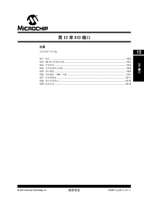
第 12 章 I/O 端口
目录
本章包括下列主题:
12.1 简介 ............................................................................................................................. 12-2 12.2 I/O 端口控制寄存器 ..................................................................................................... 12-2 12.3 外设复用 ...................................................................................................................... 12-4 12.4 边界扫描单元连接 ....................................................................................................... 12-6 12.5 端口描述 ...................................................................................................................... 12-6 12.6 变化通知 (CN)引脚 ................................................................................................. 12-7 12.7 寄存器映射 ................................................................................................................ 12-11 12.8 相关应用笔记 ............................................................................................................ 12-12 12.9 版本历史 .................................................................................................................... 12-13
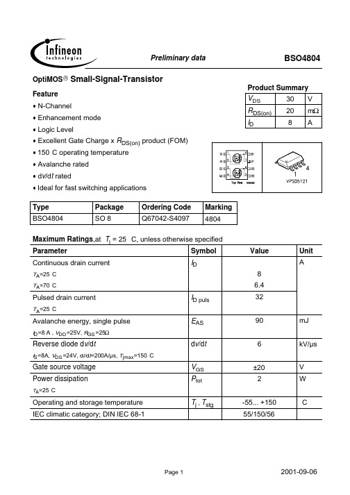
BSO4804中文资料
parameter: tp = 80 µs
40
A
6 Typ. drain-source on resistance
RDS(on) = f (ID)
parameter: VGS
65 BSO4804
m
c
RDS(on)
55
50
VGS=10V, ID=8A
VGS(th)
1.2
1.6
2
IDSS
IGSS RDS(on)
µA
- 0.01 1
-
10 100
-
1 100 nA
-
23.8 28.2 m
RDS(on)
- 17.4 20
1Device on 40mm*40mm*1.5mm epoxy PCB FR4 with 6cm² (one layer, 70 µm thick) copper area for drain connection. PCB is vertical without blown air.
45
40
35
30
25
20
15
10 VGS [V] =
5
cdef 3.2 3.4 3.6 3.8
ghi 4.0 4.5 10.0
0
0
2
4
6
8
d
e f
g h i
10 A
14
ID
8 Typ. forward transconductance gfs = f(ID); Tj=25°C parameter: gfs
ID puls EAS dv/dt
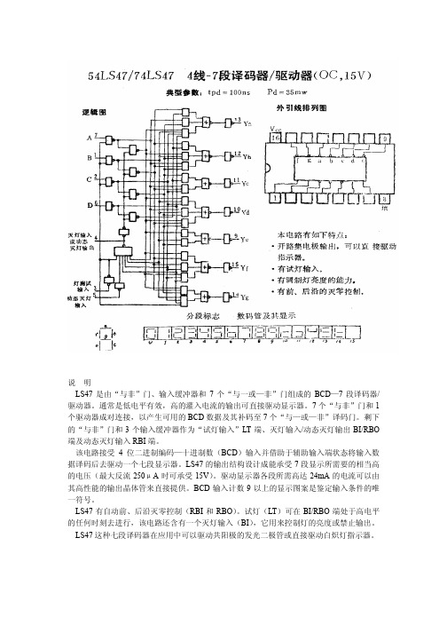
54LS47 74LS47 中文数据手册Data Sheet
70
单位
V V mA μA mA
℃
单位
V V
测试条件
V VCC =最小 II =-18mA
V VCC=最小 VIH =2V
VIL=最大 IOH =-50μA
V
IOL =1.6mA
VCC=最大VIIH=2V
IOL =3.2mA
μA VCC =最大
VIL=VIL最大
VIH =2V
VIL= VIL最大 Vo=15V
关 关 开 开 开 开开
7
H
x
LHHH
H
开 开 开 关 关 关 关1
8
H
x
HLLL
H
开 开 开 开 开 开开
9
H
x
HLLH
H
开 开 开 关 关 开开
10
H
x
HLHL
H
关 关 关 开 开 关开
11
H
x
HLHH
H
关 关 开 开 关 关开
12
H
x
HHLL
H
关 开 关 关 关 开开
13
H
x
HHLH
H
开 关 关 开 关 开开
BI/RBO 等效电路见附图 10;除 BI/RBO 外,其他输入的等效电路见附图 1。LT 和 RBI:Req=20kΩ, A、B、 C 和 D:Req=25kΩ a~g 典型输出线路见附图 17。 注:测ICC时,所有的输出端开路,输入端接 4.5V。、
BDTIC Semiconductor
/Semiconductor
IOL 输出低电平电流 54 74
54 TA 工作温度
74
符号
参数名称
SLE4442 ch

此协议为两线连接,与其他设备构成完整的 IC 电路,所有 I/O 口的数据变化都 是在时钟的下降沿开始的。
此协议包括四种模式:
- 复位与复位应答 - 命令模式 - 输出数据模式 - 内部处理模式
注意:由于 I/O 脚是开漏型的所以需要外接上拉电阻以提供高电平
第 5 页 共 23 页
2003-11-20
hSttIpE:M//EwwNw.SeSleLcEfa4n4s4.2co技m 术电子手发册烧友
电子技术论坛
Ver 1.0
2.2.1 复位与复位应答(ATR)
应答复位的发生是依照 ISO7816-3 标准,可以在操作的任何时候产生复位。开始 时给 I/O 脚低电平并在 RST 信号由高到低其间提供一个时钟脉冲,此时 I/O 脚输 出了有效数据的第一位(LSB),此后连续的 31 个时钟脉冲读出了 EEPROM 中的 4 字节标头数据,第 33 个时钟脉冲使 I/O 脚变为高阻状态完成了 ATR 过程。
模式
输出 处理 输出 处理 输出 处理 处理
第 8 页 共 23 页
2003-11-20
hSttIpE:M//EwwNw.SeSleLcEfa4n4s4.2co技m 术电子手发册烧友
电子技术论坛
Ver 1.0
2.3.1 读主存储器
电子技术论坛
Ver 1.0
2.3.4 写保护存储器
此操作包含了输入数据与原数据的比较。假设输入的数据与要保护的数据一致, 则该地址的数据将不能在改写了;如果比较的结果不同,那么此次操作无效。
例如:
主存储器 10H 单元的数据为 3DH,现在要保护此单元的数据不被改写。
1484培训手册

目录第一部分总介----------------------------------------------------------1第二部分机械结构----------------------------------------------------2第三部分机械方块图-------------------------------------------------3第四部分板子简介----------------------------------------------------4第五部分各部分介绍-------------------------------------------------5第一章电源供应部分-----------------------------------------6第二章 主架及控制--------------------------------------------10第三章 驱动磁碟--------------------------------------------- -18第四章 光学及影像/PRS--------------------------------------19第五章 打线头/电子点火/超声波振荡----------------------24第六章 X/Y TABLE----------------------------------------- --37第七章 校正程序------------------------------------------------38第八章 工作台的设定------------------------------------------45第九章 故障排除------------------------------------------------62第一部分 总介一技术规范X---Y 工作台解析度0.1milsX---Y工作台精度: 0.15mils打线速度: 115ms/根.标准值 线径: 0.7---2.0mlis 线长: 20---250mils料盒间距: 80---540mils气压: 60---100p si第三部分机台总控制方框图第四部分板子简介板子机台编号主MPU板 1484 01483-40351488 01483-4046主逻辑板 1484 /1488 01484-4029RAM板 1484 797-4188超声板 1484 01483-40121488 01483-4047图象板 1484 /1488 01483-4033X模拟板 1484 01483-4005XX数字板 1484 01483-4001Y模拟板 1484 01483-4005YY数字板 1484 01483-4001Z模拟板 1484 01483-4005ZZ数字板 1484 01483-4014X/Y功放板 1484 01483-10311488 01483-1031Z功放板 1484 01483-10331488 01483-10741484 01483-1037工作台CPU板 1484/1488 02920-4035传感器板 1484/1488 02920-4160电磁阀板 1484 06150-40301488 02920-4030升降台半步进板 1484 /1488TURBO 0797-4235 1488PLUS 02920-4235升降台多控制板 1484/1488TURBO 6100-4330 1488PLUS 02920-4330工作台半步进板 1484/1488TURBO 0797-4235 1488PLUS 02920-4235工作台多控制板 1484 /1488TURBO 6100-4330 1488PLUS 02920-4330左夹子步进板 1484/1488TURBO 0797-4315/I 1488PLUS 4318/I右夹子步进板 1484/1488TURBO 0797-4315/E 1488PLUS 4318/E检测板侧灯/同轴灯控制板PRS板第五部分各部分简介第一章 电源供应部份一 电源供应组成电源箱和绝缘变压器组成<一> 电源箱见图1-2主要的电源供应有一个分离的空气开关控制当开关打开(ON) 时电源箱针对电脑控制及伺服马达供应会产生+5V +12V ±15V ±28V 的DC 输出及产生120V 交流供应风扇及便利扦座1. 输入选择1.1.1 目的为了保证电源箱输入与输入电压相一致1.1 .2检查程序(1)切断总电源(2)打开机台左边的柜门(3) 在电源箱的左侧下方有一电源配制装置<见图1-1>(4) 移走电源配制片外的玻璃罩子(5) 选择适合我们市电220V 交流 的配置将220V交流调整到箭头方问(6) 配制片上2个保险丝是该电源箱的备用保险丝图1-1 输入配置图2. 直流(DC) 电压的检查与调整2.1 目的为保证直流电压的供应在指定范围之内2.2检查与调整程序(1) 移走机台正前方左侧的柜门及机内过滤网(2)检查电源箱下端电极方块连接器(见电源箱图1-2)A检查+28Va: 将万用表连接到电极方块的1和13之间b: 打开机台总电源检查瞬间跳动由+25---+30.8之间B检查及调整背板测试点的电压+5v(1)测量接地(DG) 与+5V之间(2)电压应在+4.90与+4.93V之间(3)若不在此范围则可调整电源箱前面标有+5V ADJ的电位器+15V(1)测量点(AG) 与+15V之间(2)电压应在+14.80与+15V之间-5V(1)测量点(AG) 与--15之间(2)电压应在+15V量值的0.23之间3检查调整磁碟机上的电压+5V(1)测量点位于白/红或红色(+)电线及黑色或褐色(-)之间(2)电压必须为+4.76---+5.25V(3)若不准则调整电源箱上标有+5V.ADJ的电位器+12V(1)测量点位于白色或黄/白电线及黑色或褐色之间(2)电压必须为+11.76--+12.24V附直流电压调整表电压位置机台状态范围调整+28V电源供应条块未端STOP按下+25.0---+30.8V+5V背板测试点DG“+5V”STOP按下+4.90---+4.93调整电位器+5V.ADJ+15V背板测试点AG+15V STOP按下+14.80--+15.15 -15V背板测试点AG-15V STOP按下+15V少0.23驱动磁碟的+5V 连线的白/红或红. 黑或褐STOP按下+4.75到+5.25调整+5V.ADJ驱动磁碟的+12V 连线的白/黄或白. 黑或褐STOP按下+11.76到+12.24<二>绝缘变压器见图 1-3主要是提供机台平台下的左前缘的二个便利扦座.Z放大板. 直流电源供应及机台预加热温度及机柜内的灯光及焊线区的工作灯光1.输入选择主要是针对市电220V选择输入变压器电压为220V(1) 输入端选择为1(RED) 及5D(BLACK) RED及BLACK为线的颜色(2) 跳线端子应为2---3连 4----5B连(以上见绝缘变压器图1-3)<三>空气过滤网位于机台前下左侧柜门内目的是保证机台内空气流通<四>紧急停止钮仅限1488位于机台前左上方红色按钮,主要是当危及人员的紧急事件时来切断电源.第二章主架及控制一主架及控制1. 介绍1484XQ/LXQ 1488TURBO/PLUS机台的程式及操作乃由机器软体(存储在硬碟或软碟)资料处理及电子介面(电脑主架) 等操作员控制之间的互动来完成的下面主要针对电脑主架/控制机器键盘控制面极气动元件及温度控制器提供帮助2. 主架2.1 介绍1484XQ/LXQ 1488TURBO/PLUS所有功能是由主处理单元(MPU)所控制资料的反应由EPROM所提供或者由硬碟或软碟到RAM中载入资料MPU命令及对附属的处理器座标个别控制XY滑轨Z轴焊头及MHSPRS驱动磁碟链盘及FTCP影像显示 USG 及EFO来连结MPU的所有电子元件被含在PC板上MPU及主逻辑板且每块板子提供LED指未灯及测试点来检查及排理故障2.2 主架PC板2.2.1 主MPU板1484XQ/LXQ为01483-40351488TURBO/PLUS为01483-40462.2.2 见图为MPU板主要控制图2-22.2.3 下表所列MPU的LED错误码O 0 没有定义,MPU没电源 OOOO 1 RAM测试失败OO●O 2 ROM测试失败OOO 3 RAM测试失败OO 4 开机期间磁盘错误OOO 5 电源中断OO 6 影像控制器错误O6 影O 7 影像RAM测试失败8 磁盘无法开机OOO9 起始化错误OO10 RAM相同的错误中断OO11 执行软件的错误操作及还原过程 O12 目前未实行资料的LED有缺陷OO13 目前未实行资料的LED有缺陷O14 目前未实行资料的LED有缺陷O15 正常2.2.4主逻辑板图2-4下面通过列表来表示主逻辑板的控制功能功能控制器/指示器测试点提供MPU的内容到PRS 系统系统控制压力器键盘EFOFTCP(控制面板)温度控制器讯号灯电源供应XYZ伺服放大器Z限制停及E--STOP讯号产生系统伺服及逻辑活性紧急停止LEAS提供MPU实际时钟提供MPU LEAS计时器(检测MPU故障)提供执行逻辑时钟控制打线接口LAES LED(DSI)一般为OFF灯光指示局部的逻辑开动紧急停止(必然错识或马达停止)MPU LAES LED(DS2)一般为OFF LED灯光指示MPU LAES的错误(必然错误)伺服功能LED(DS3)一般为ON表示伺服马达的逻辑功能假若伺服被关闭LED变暗机器错误或马达停止开关供应低/OK LED(DS4)一般为ON表示放大器的电源供应正在输送电压LED变为OFF指示放大器有问题TP1打线头混合接触信号3. 3. 操作员的控制3.1 键盘键盘包括32个按键(8列4行)位于最左边一行及最上面一行的按键包含有LEDS灯这些灯用来指示主MPU软件控制若灯亮时则该灯指示的功能为有效状态按一下按键会产生一个闪光脉冲和一个单一的二位进制数将内容传送到主逻辑板3.2控制面板(FTCP)包括两组编码钮用来手动控制打线头及XY滑轨的运动编码器的输出通过伺服控制电路上的伺服放下器经主逻辑板MPU3.3 开关马达停止键(MOTORS STOP) 自动送片(AUTO INDEX)及连续停止键(SEQUENCE STOP) 均为自锁开关错误键(ERROR) 送片键(INDEX) 输入键(ENTER)均为不自锁开关按一下以上这些开关将送出讯号给MPU以执行需求的功能4气动系统4.1 介绍1484XQ/LXQ 1488 TURBO/PLUS机台的气动系统设备是由单一气源引入压缩空气及真空送线系统及2920工作台图示为气动控制的结构图输入气压经空气过滤器控制阀调整压力到60---65PSIG调节气阀的仪表供给使用者2920型工作台调节的气流压力被通过气阀来控制气缸的压力这些气阀来控制输入输出升降台料盒的锁定及推出气流也被用于送线组件上的气流道轨及打线区上的张紧器组件张紧器的气流直接由流量计来控制2920工作台及加热块及送线系统的真空张力器都要用到真空流量计真空马达用输入的气压来创造真空通过真空张力器的真空都需通过调节按钮来调整而加热块的真空则直接由真空线路马达的气阀来控制使用者无法调节或控制加热块的真空4.2 调整目的:设定需要的输入气压程序:检查仪表上的压力读数是否在60---65PSI内若不是则调节5. 温度控制器(见图2-7 )温度控制器提供交流电源给工作台的加热块及预热块来产生合适的打线温度其中一个温度控制工作台预热区的温度一个来控制加热区的温度5.1 简介温度控制器提供102—135VAC电压给工作台的加热器都是有由一个开关和一组保险丝来达到目的(1484系列保险丝在机台下方1488则在机台上方)操作时控制器设定的温度应与加热器上的温度作一比较若有差异则应调整5.2 调整目的为设定合适的加热块与预热块的温度程序(1)将加热器开关打开(ON)(2)按下温度控器上的回归键一次控制器将显示目前温度的设定点(此时SP指示灯亮)(3)通过回归键调整温度设定点(4)按回归键三次控制器将显示目前加热块的温度(5)等加热块温度稳定后用点温计检查加热块温度是否与设定的温度一致若不是则按以下步骤调整补偿值A:按回归键三次B:温度控制器显示目前的补偿值C:当实际温度高于设定点时若补偿值正确则最左边应显示”H”D: 当实际温度低于设定点时若补偿值正确则最左边应显示”L”E:当实际温与设定点有温度差时应调整补偿值欲将高补偿值变为低补偿值则按向下键直到出现”L”反之则按向上直到出现”H”第三章 驱动磁碟一简介磁碟系统由一个3.5英寸的软碟和一个硬碟组成两个磁碟的操作及资料转换是由MPU通过电脑系统的I/O接口来送出及接受资料1484/1488在操作过程中一般使用硬碟二硬碟FORMAT1.打开焊线机;2.按装系统磁盘于软碟中;3.开动和起始化球焊机将有软碟入资料;4.进入公用程式选择磁碟利用;5.选择FORMAT;6.当完成后将A:中的资料拷贝到硬碟中第四章光学影像 /PRS一简介(图4-1)光学系统包括光学灯光摄像机监视器及影像处理系统电子元件扩大化影像显示及图形显示影像系统的屏幕产生程序是由860型PRS所执行的此系统加入了VLL定位及自动PAD中心找寻能力来增强PRS调整的能力注1488PLUS是由870PRS系统来控制的VLL有高速影像分析的能力这可以使球焊机能够在焊线前发现框架外脚这特别适用于高脚数及管脚空间很靠近元件及元件宽度及位置的变化较高的元件并在最短的循环时间影响下提供加强精焊打线的能力自动PAD找寻的特性被设计来增强教读打点PAD 定位时的速度及精度当打开时由操作员标定的PAD 打点位置由PAD光学找寻中心重新定位的能力二影像路径影像的路径由摄像机开始摄像机的电缆位于外壳的右后方摄像机的视屏信号经由控制器被送到位于机器外壳后面的860870型PRS板子三显微镜(略)四斜射灯光1简介斜射灯光是由六个高强度用并环形排列的LEDS装置所组成的该灯光被装置在附属于左边光学基座的托架上其强度控制可通过键盘来控制1.1目的:是为了提供良好的影像亮度及浓度,以利于观看及影像辨识1.2设定A: 确定元件位于打线位置B: 使用X-Y编码钮将元件定于监视器荧幕中心C: 进入公用程序(UTILITIES)摸式D: 按"C"键(设定程序)E: 按"F"键(下一面)F: 按"B键(PRS灯光设定)G: 按"E"键改变灯光H: 按"复位"键,出现内定的灯光值,相应灯光会被调整I: 检查影像灯光是否均匀没有反射的区域J: 使用上/下箭头改变斜射灯光值,刻度由0-15K: 依需要设定斜射灯光,以消除高度射区域五直射灯光1: 简介直射灯光是由装在反射器内的高强度LEDS所组成,此灯光安装在摄影机透镜上面的摄像机光学组件之内.2: 设定调整方法同斜射灯光相似.六: LED驱动板该板子位于PRS板下方.七: 光学仪器1: 简介光学系统的组成是由光学组件及固定摄像机,光学组件的构成分为透镜,反射镜降凝器.2: 设定(1) 焦距图8-3A: 用X-Y编码将芯片定于监视器中央B: 松开接物透镜的夹头螺丝C: 依需要转动凸镜以获取清晰图象D 旋紧夹头螺丝(2) 线性的图4-2 目的 为确保PRS 辨识时摄像机对准X 轴和Y 轴 调整 参考PRS 光学校正 (3) 倍率图4-2 目的 为建立PRS 位置校正时画面影像像素与元件实际区域间的关系调整参加PRS 光学校正 3注意事项 接物透镜的镜面不能用酒精溶剂擦拭只能使用棉布或擦镜纸八有管脚定位的VLL/PRS 系统(1) 简介 PRS 将影像的讯号由摄影像机转化为数字资料以求取布景的第一图象及位置即一个眼点EYE POINT 接着这些资料被用在自动焊线期间的相位调整以获取目前器件的打点位置当校读了一个打线程式时PRS 系统VLL 定位传感指示在打线之前获得管脚资料主要用于支架脚数字及空间较密或元件之间脚的密度及位置变异性较大的元件 (2) PRS 板 位于机台后面 注意1为防止损坏设备当打线机起动时不要插拔PRS 板上的任何电源 2当更换PRS 板时必须考虑防静电使用手环或穿防静电工作服 (3) PRS 的写入 此程序主要用来PRS 丢失或失效后重新装入PRS 系统此程序包括两张第五章 打线头/电子点火(EFO)/超声波振荡一简介实际的打线过程的完成是由下列机械结构及控制系统1. 打线头(见图5-1)图5-1 打线头马达驱动的组件将打线头升起或下降应用压力及超声波的能量来打线并于第二点断线并且包含了EFO组件能在第一点打点前形成金球2送线马达线轴装置及空气压力/真空元件3打线头的控制PC板产生的电脑控制的准确度能控制打线头的移动和操作4电子点火EFOPC板产生的高压来形成金球5超音波振荡器PC板产生的超声波能量来传送到打线工具6打线检测系统WBMS直流DC打线检测系统是针对打线过程的结果执行检测二打线头1.打线头执行的有动作及操作需求来将金线打在元件表面打线头的基本元件如下1Z-马达Z-马达为一线性马达能驱动打线头的动能元件连接器能量转换器马达由连接器/劈刀的位置回转及打线力量而驱动连接器/劈刀的位置由接近传感器来检测而打线力量直接由Z马达来驱动2连接器其作用是将所有的打线头动态元件连在一起其结构为A平衡打线头B提供超音波振荡良好的基础C在两个动态元件间提供机械耦合D遮盖接近传感器感应的信号柄E连接枢轴在的四片簧片3超音波振荡能量转换器该能量转换器是以振动的形式将电能转换为机械能振动被用在打线的过程中4线夹断线操作期间线夹夹紧金线故能提供线尾来形成金球线性马达驱动线夹经由弹力关闭线夹并由马达打开线夹5电子点火EFOEFO将电能转换为热能用以在金线在形成金球电子点火的完成是在金线及打火杆间形成电位差来达到电火化电能通过火化在间隙融化尖端的金线然后形成金球2.劈刀安装(1) 目的为确保良好的打线品质延展性固定劈刀务必旋紧螺丝(2) 程序a:按下马达停止键(MOTORS STOP)b:关掉真空张紧器及气流道块压缩气c:从劈刀中移走金线d:松开劈刀螺丝并移走旧劈刀e:将新劈刀装入专用量轨内f:用手指将能量转换器移到最高点g:将劈刀插入劈刀夹头h:让劈刀量轨及能量转换器一直下降碰到工作台压板I:旋紧劈刀螺丝J:执行超能量转换器及校正十字线补偿程式3.电子点火杆图5-2目的主要是为了校正电子点火尖端与劈刀间的相对位置以得到最大的电子点火效率校正a:进入公用程式b:选取设定高度c:按F键打开Z转盘d:用右编者按码将劈刀向下转动直到显示Z=-850e:松开电子点火杆前端的固定螺丝,松开电极夹头螺帽,依下列步骤重新定位电子点火组件及打火杆以得到需求的正确设定1:确定打火杆尖端的位置正好对准劈刀直径中心2:确定EFO在Z=-850时正好与劈刀尖端成水平3:慢慢将劈刀向下转动并观察劈刀边缘与EFO杆的间隙为7--13MIL间4:调正过后须锁紧硬件5:执行电子点火高度校正程序附当打火杆EFO尖有灰尘及污染物时可采用酒精棉签擦拭4 线夹线夹夹头轴承是一对人造宝石所构成(1).清洁线夹目的1线夹操作不正常2发生打线检测系统WBMS假停止第一点不粘工具干净白色的无毛球纸酒精程序清洁线夹时应在打线机电源打开时a进入手动MANUAL模式A键b: 按ERROR键打开线夹c: 将金丝自线夹夹头取出d: 将酒精洒在纸上弄湿e将弄湿的纸插入线夹夹头间f按ERROR键关闭线夹g在线夹间来回抽动纸张h按ERROR键打开线夹i将下净的纸插入线夹间j按ERROR键关闭线夹k在线夹间来回抽动纸张l以一种平顺的方式自线夹内抽出纸m抛弃纸张n按下ERROR键检定线夹夹头内的宝石是否于净o按下ERROR键关闭线夹p依需要重复以上步骤q检查马达是否清洁是否有妨碍线圈移动的物质夹在磁槽内(2).线夹间隙的调整/检查图5-3目的确保线夹夹头间的距离正确以避免撞击金线的力量过高避免金线受损程序a检查线夹的间隙是否在线径的2---3倍b用005英寸的板手转动间隙调整螺丝如下示来求得需要的设定反时针方向增加间隙顺时针方向减小间隙(3).玻璃送线导管的检查/调整(图5-3)目的为确保存在于玻璃送线导管中的金线能够对准线夹的中心程序a在机台的手动模式下按ERROR打开线夹b检查位于玻璃导管间的线夹是否自由通过线夹的中心c若金线不在中央则执行以下调整使用六角板手依下列步骤调整(1)反时针将导管移向左边(2)顺时针将导管移向右边(4).线夹组件的移动及按装图5-4目的提供置换线夹组件的程序程序1.关掉打线机的电源a:按下马达停止键b:关掉总电源2.若有需要自线夹组件及金线张紧器道块中取出金线3.移走固定线夹组件的螺丝4.移走光学组件5.移走固定线夹组件的螺丝6.注意各束带及扣环7.移走固定打线检测系统送线线夹上的螺丝及导线8.由打线头移下线夹组件9.按装过程是移下过程的反过程(5).能量转换器的调整/检查图5-5目的为确保换能头直于工作台表面检查1.进入手动模式2.将金线从劈刀中移走3.检查L/F的劈刀a:标定管脚b:依需要可按输入键两次直到劈刀印清晰c:使用劈刀印应为圆形而不是半圆形若劈刀不是圆形则按以下调整按下马达停止键松开能量转换器的两个螺丝调整能量转换器使劈刀垂直于工作台表面然后锁紧螺丝依需要再次调整6接近传感器该接近传感器用来在最低点执行打点一般显示为Z=-368075 7轴承弹簧片当出现以下类情况时需更换或调整*当按下马达停止键时劈刀没有随着下降而下降*打线间劈刀没有碰到工作表面*打线力量的校正超出指定范围*z解析度超出指定范围更换方法1.关掉打线机2.移走光学组件3.检查轴承弹簧片是否破裂及是否交叉成90度4.若不合要求则更换5.装回光学组件6.打开打线机7.执行教读十字线补偿程序5.送线图5-61简介送线系统由下列组成*马达线轴装置控制及转动线轴以提供打线需要的正确金线长度电子点火触发时马达被触动预选送出金线送线的控制对1488来说是由光学感受应器控制的对1484来说是由接触感应器控制在线轴和打线头间保锱一段或多或少的一定长度的金线*真空张紧器提供金线张力*手动送线钮当按下此按钮时线轴动转动2线轴的设定线轴的设定由顺时针和逆时针方向两种状态对1484来说其转动方向的调整在检测板上对1888来说其转动方向的调整在菜单D --C---F4--E---C中来调整3金线真空张力器的设定目的为检查金线的张力是否足够主要检查以下几个项目:*金线打点有没有"线尾"匙形球*线弧的一到性送线的维护A:清洁送线真空张紧器的玻璃管和陶瓷管目的:为预防积聚的灰尘及金线润滑油,妨碍金线通路周期:大约一星期一次程序:(1)进入手动模式(2)按下ERROR键打开线夹(3)取下金线,取下玻璃管(4)检查以确定玻璃管又没有损坏或破裂,若不良则更换(5)松开陶瓷块夹头螺丝(6)取下陶瓷管(7)检查陶瓷管,若不良则更换(8)清洁玻璃管及陶瓷块(9)完成后装回玻璃管及陶瓷管6.打线头的控制6.1简介打线头的所有功能控制,是由MPU板,Z轴伺服板,Z轴放大板及主逻辑板完成,针对伺服马达的控制,Z马达使用接近传感器提供马达的位置信号给伺服板,由主MPU及Z轴伺服板定义的数字信号由Z放大板上的放大器转换为模拟信号来驱动马达,主逻辑板用来控制信号提供给MPU板6.2电子组件1 Z轴伺服板对1484来说Z轴伺服板由俩块组成4005Z和4014对1488来说Z轴伺服板由俩块组成01483-4204-000其主要功能为1监视马达的位置2执行主MPU移动计算的要求3将数字信号转换成模拟信号4针对马达位置的移动将接近传感器的输出转变为数字信号5作为Z方向驱动器电子点火及超声波振荡发生器的界面6将机器参数存储于RAM中(2)z轴放大器对1484来说Z轴放大板的编号为01383-1033对1484来说Z轴放大板的编号为01483-1074其主要功能为由Z轴伺服板到驱动Z马达的放大伺服控制信号*提供28V53V43V的电源供应给X-Y放大器7电子点火针对1484/1488系列其打火控制为负电压其主要功能*提供控制电子放电以形成金球电流及电流周期由主MPU经主逻辑板控制*控制放电检测SHORT/OPEN8.超音波振荡产生器USG8.1简介超音波振荡器由主架内的P.C 板组成,该P.C 板为一片自我容纳相位锁定回路控制超音波振荡能量转换的驱动器,USG 板供应定电流,定电压来执行操作输出模式,经由主MPU 控制器来求出一中心频率,在打线过程中产生能量转换器的共振频率 8.2 USG 板的主要功能如下:功 能控 制 器/指 示 器针对能量转换器产生超音波振荡频率*可以选择定电流,定电压*针对对应的负载可程式化的输出阻抗(1488)*当USG 打开时灯亮*当USG 关闭时灯灭8.3 超音波振荡能量的应用 8.3.1超音波振荡电压的波形(1) 方波BP=程式的打线功率(2) 梯形波此波提供了超音波振荡绶慢打下降包括在全部的打线时间内,且它们是线性的,其倾钭上升及下降时间相同 BTBP=程式的打线功率BT=程式的打线时间波功率的准位等于程式的打线功率加上40,然而最大的突波准位不可大于255,突波的周期为积聚在管脚上的氧化物或其它BT8.3.2 T程式的波形操作员针对特定的打点选一打线参数,并由此输入适当的数字指定相应的波形,选择如下:A:到达想要的打点B:按下A键C:选择打点参数,显示器将显示目前打点参数的数值,按下方向键转换屏幕上的第1.2点参数,若想要变打点参数则按"F"键D:选取想要的波形输入*输入1为方波*输入2为梯形波*输入3为突波E:输入后按ACCPT8.3.3定电压或定电流输出此功能被用于*每个个别的打点*每根打线*一个参考系统*全部打线9.打线检测系统(WBMS)9.1简介打线检测系统被用来侦测下列的打线缺点:*铝垫不粘(NSOP)*管脚不粘(NSOL)9.2打线检测系统为一连续的检测器,能够产生一个逻辑准位的输出信号给打线循环期间,此信号能用来监视打线过程中的不同的打点,一个3V的电池经由大电阻被连到导线,将置放一个电位在导线上,因为被打线的元件已被接地了,当金线成功地被打在器件上时,将流过一个小信号电流,当金线脱落时,将没有电流流过.9.3打线系统检测的选项:打线检测系统包括正和负两种极性(1488还有高低电流)*对1488来说,其极性的选择为:主菜单-ÆDÆCÆFÆEÆA,B*对1484来说 其极性的选择直接在检测板上。
mvtx2804中文资料_数据手册_IC数据表

configuration
• Packaged in 596-pin BGA
Description
The MVTX2800AG family is a group of 8-port 1000 Mbps non-blocking Ethernet switch chips with on-chip address memory. A single chip provides a maximum of eight 1000 Mbps ports and a dedicated CPU interface with a 16/8-bit bus for managed and unmanaged switch applications. The VTX2800 family consists of the following four products:
• CPU interface supports 16/8-bit CPU bus in managed mode and a synchronous Serial Interface and I2C interface in unmanaged mode
• SNMP/RMON support with CPU
- Provide Hot plug support for GMII/PCS module
- 2 Gigabit ports can be aggregated into 2Gbps Stacking port working with VTX260Biblioteka in stacking mode
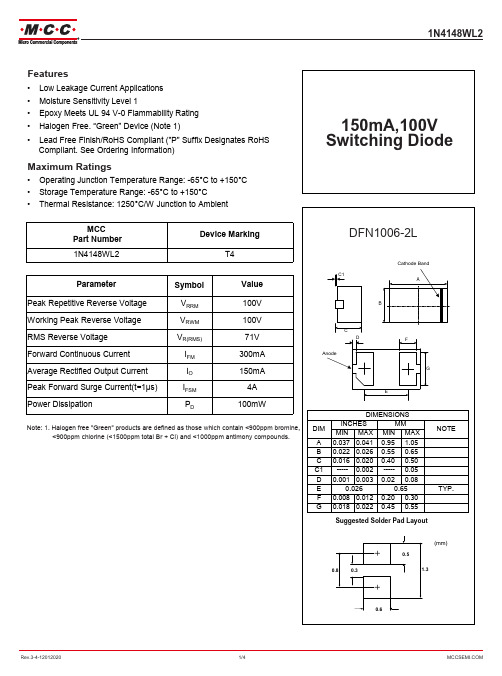
1N4148WL2 Switching Diode数据手册说明书
40
60
80
100
Reverse Voltage (V)
Rev.3-4-12012020
3/4
Ordering Information
Device Part Number-TP
1N4148WL2
Packing Tape&Reel: 10Kpcs/Reel
***IMPORTANT NOTICE***
***CUSTOMER AWARENESS***
Counterfeiting of semiconductor parts is a growing problem in the industry. Micro Commercial Components (MCC) is taking strong measures to protect ourselves and our customers from the proliferation of counterfeit parts. MCC strongly encourages customers to purchase MCC parts either directly from MCC or from Authorized MCC Distributors who are listed by country on our web page cited below. Products customers buy either from MCC directly or from Authorized MCC Distributors are genuine parts, have full traceability, meet MCC's quality standards for handling and storage. MCC will not provide any warranty coverage or other assistance for parts bought from Unauthorized Sources. MCC is committed to combat this global problem and encourage our customers to do their part in stopping this practice by buying direct or from authorized distributors.
AO4844中文资料

5.8554SymbolTyp Max 4862.574110R θJL 3540Steady-State °C/W Thermal Characteristics Maximum Junction-to-LeadCSteady-State°C/WParameterUnits Maximum Junction-to-Ambient A t ≤ 10s R θJA °C/W Maximum Junction-to-Ambient AAO4844AO4844SymbolMin Typ MaxUnits BV DSS 3035V 0.0041T J =55°C5I GSS 100nA V GS(th)1 1.723V I D(ON)20A 2228T J =125°C31.3383242m Ωg FS 1015.4S V SD 0.741V I S3A C iss 680820pF C oss 102pF C rss 77pF R g3 4.5ΩQ g (10V)13.8417nC Q g (4.5V) 6.748.1nC Q gs 1.82nC Q gd 3.2nC t D(on) 4.67ns t r 4.1 6.2ns t D(off)20.630ns t f 5.27.5ns t rr 16.520ns Q rr7.810nCTHIS PRODUCT HAS BEEN DESIGNED AND QUALIFIED FOR THE CONSUMER MARKET. APPLICATIONS OR USES AS CRITICAL COMPONENTS IN LIFE SUPPORT DEVICES OR SYSTEMS ARE NOT AUTHORIZED. AOS DOES NOT ASSUME ANY LIABILITY ARISING OUT OF SUCH APPLICATIONS OR USES OF ITS PRODUCTS. AOS RESERVES THE RIGHT TO IMPROVE PRODUCT DESIGN,FUNCTIONS AND RELIABILITY WITHOUT NOTICE.I F =6.9A, dI/dt=100A/µsI F =6.9A, dI/dt=100A/µsElectrical Characteristics (T J =25°C unless otherwise noted)ParameterConditions STATIC PARAMETERS Drain-Source Breakdown Voltage I D =250µA, V GS =0V I DSS Zero Gate Voltage Drain Current V DS =24V, V GS =0VµA Gate-Body leakage current V DS =0V, V GS =±20V Gate Threshold Voltage V DS =V GS I D =250µA On state drain currentV GS =4.5V, V DS =5V R DS(ON)Static Drain-Source On-ResistanceV GS =10V, I D =6.9Am ΩV GS =4.5V, I D =5.0AV GS =0V, V DS =0V, f=1MHzForward TransconductanceV DS =5V, I D =6.9ADiode Forward Voltage I S =1A Maximum Body-Diode Continuous CurrentDYNAMIC PARAMETERS Input Capacitance V GS =0V, V DS =15V, f=1MHz Output Capacitance Gate Drain Charge Reverse Transfer Capacitance Turn-On Rise Time Turn-Off DelayTime Gate resistanceBody Diode Reverse Recovery TimeBody Diode Reverse Recovery Charge Turn-Off Fall TimeSWITCHING PARAMETERS Total Gate Charge Total Gate Charge Gate Source Charge Turn-On DelayTime V GS =10V, V DS =15V, R L =2.2Ω, R GEN =3ΩV GS =10V, V DS =15V, I D =6.9AA: The value of R θJA is measured with the device mounted on 1in 2 FR-4 board with 2oz. Copper, in a still air environment with T A =25°C. The value in any given application depends on the user's specific board design. The current rating is based on the t ≤ 10s thermal resistance rating.B: Repetitive rating, pulse width limited by junction temperature.C. The R θJA is the sum of the thermal impedence from junction to lead R θJL and lead to ambient.D. The static characteristics in Figures 1 to 6 are obtained using 80 µs pulses, duty cycle 0.5% max.E. These tests are performed with the device mounted on 1 in 2 FR-4 board with 2oz. Copper, in a still air environment with T A =25°C. The SOA curve provides a single pulse rating. Rev 0: Apr. 2006AO4844TYPICAL ELECTRICAL AND THERMAL CHARACTERISTICSAO4844。
AD4111低功耗24位Σ-Δ型ADC数据手册说明书

Rev. 0Document FeedbackInformation furnished by Analog Devices is believed to be accurate and reliable.However, no responsibility is assumed by Analog Devices for its use, nor for any infringements of patents or other rights of third parties that may result from its use. Specifications subject to change without notice. No license is granted by implication or otherwise under any patent or patent rights of Analog Devices. Trademarks andregistered trademarks are the property of their respective owners.One Technology Way, P .O. Box 9106, Norwood, MA 02062-9106, U.S.A.Tel: 781.329.4700 ©2018 Analog Devices, Inc. All rights reserved. Technical Support /cnADI 中文版数据手册是英文版数据手册的译文,敬请谅解翻译中可能存在的语言组织或翻译错误,ADI 不对翻译中存在的差异或由此产生的错误负责。
如需确认任何词语的准确性,请参考ADI 提供的最低功耗24位Σ-Δ型ADC ,±10 V 和0 mA 至20 mA 输入,具有开路检测功能数据手册AD4111特性集成模拟前端的24位ADC每通道最高6.2 kSPS (每通道161μs ) 1 kSPS 时每通道16位无噪声分辨率50 Hz 和60 Hz 抑制:85 dB (20 SPS ,每通道) ±10 V 输入,4个差分或8个单端 超量程高达±20 V ≥1 MΩ阻抗25°C 时精度为±0.06% 开路检测0 mA 至20 mA 输入,4个单端 超量程从−0.5 mA 至+24 mA 60Ω阻抗25°C 时精度为±0.08% 片内2.5 V 基准电压源25°C 时精度为±0.12%,温漂为±5 ppm/°C (典型值) 内部或外部时钟 电源AVDD = 3.0 V 至5.5V IOVDD = 2 V 至5.5 V 总I DD = 3.9 mA温度范围:−40°C 至+105°C3线或4线串行数字接口(SCLK 上为施密特触发器) SPI 、QSPI 、MICROWIRE 和DSP 兼容应用过程控制 PLC 和DCS 模块概述AD4111是一款低功耗、低噪声、24位Σ-Δ型模数转换器(ADC),集成了模拟前端(AFE),支持全差分或单端、高阻抗(≥1MΩ)双极性±10 V 电压输入和0 mA 至20 mA 电流输入。
OP484中文资料

RL = 2 kΩ To 0.01%, 1.0 V Step
1.65
0.1 Hz to 10 Hz f = 1 kHz
NOTES 1 Input Offset Voltage measurements are performed by automated test equipment approximately 0.5 seconds after application of power. Specifications subject to change without notice.
元器件交易网
a
FEATURES Single-Supply Operation Wide Bandwidth: 4 MHz Low Offset Voltage: 65 V Unity-Gain Stable High Slew Rate: 4.0 V/ s Low Noise: 3.9 nV/√Hz APPLICATIONS Battery Powered Instrumentation Power Supply Control and Protection Telecom DAC Output Amplifier ADC Input Buffer
Precision Rail-to-Rail Input & Output Operational Amplifiers OP184/OP284/OP484
PIN CONFIGURATIONS 8-Lead Epoxy DIP (P Suffix) 8-Lead SO (S Suffix)
NULL –IN A +IN A V– 1 2 3 4 NC = NO CONNECT
60 2 0 60 86 50 25
硅表说明书
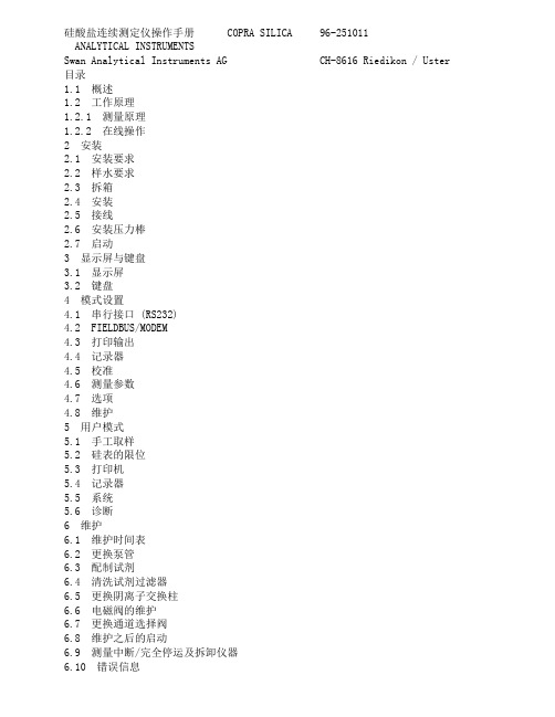
硅酸盐连续测定仪操作手册 COPRA SILICA 96-251011ANALYTICAL INSTRUMENTSSwan Analytical Instruments AG CH-8616 Riedikon / Uster 目录1.1 概述1.2 工作原理1.2.1 测量原理1.2.2 在线操作2 安装2.1 安装要求2.2 样水要求2.3 拆箱2.4 安装2.5 接线2.6 安装压力棒2.7 启动3 显示屏与键盘3.1 显示屏3.2 键盘4 模式设置4.1 串行接口 (RS232)4.2 FIELDBUS/MODEM4.3 打印输出4.4 记录器4.5 校准4.6 测量参数4.7 选项4.8 维护5 用户模式5.1 手工取样5.2 硅表的限位5.3 打印机5.4 记录器5.5 系统5.6 诊断6 维护6.1 维护时间表6.2 更换泵管6.3 配制试剂6.4 清洗试剂过滤器6.5 更换阴离子交换柱6.6 电磁阀的维护6.7 更换通道选择阀6.8 维护之后的启动6.9 测量中断/完全停运及拆卸仪器6.10 错误信息警告仪表符合DIN57411 part 1/VDE 041 part 1、“电子测量仪保护措施”,并且在无故障条件下出厂。
为了保持这种无故障状态和保证无操作错误,用户必须重视所有的警告并且严格按照《操作手册》操作。
严禁不接地。
外部或内部保护地线的断裂或松弛可能会导致危险。
当需要进行电气检修时必需在未通电状态下。
打开仪表或移动其部件时须小心,连接应紧固。
检修须由指定人员进行。
若仪表不能正常运行,就必须切断所有电源,并停止操作。
如有下述情况发生,不能进行安全操作:- 在运输或安装过程中明显损坏。
- 仪表不工作。
- 在不良环境下储存期过长仪表附件的任何连接都必须按照IEC 950/EN 60950,UL1950或UL478标准。
注意:没有试剂仪表不能工作。
试剂可以在Swan公司各地的经销商处购买。
Si4844 中文数据手册
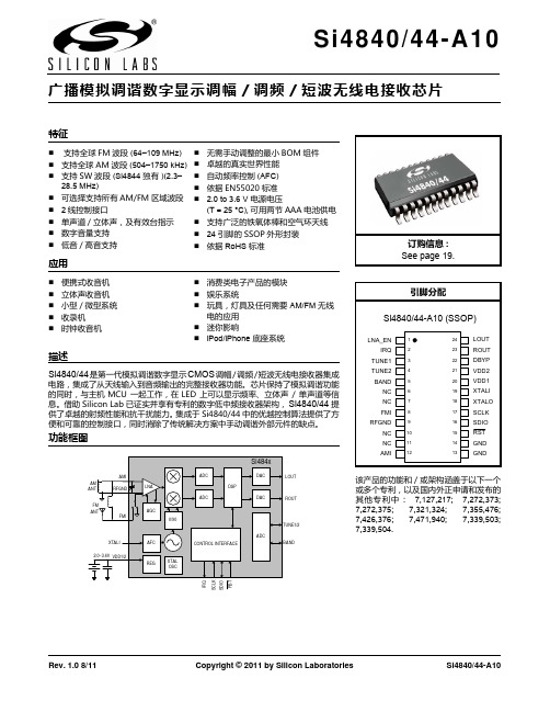
Si4840/44 是第一代模拟调谐数字显示 CMOS 调幅 / 调频 / 短波无线电接收器集成
功能框图
Si484x Si4830/34
AMI AM ANT FM ANT RFGND LNA ADC AGC 0/90 ADC XTALI 2.0~3.6V VDD1/2 REG AFC CONTROL INTERFACE XTAL OSC SCLK SDIO IRQ RST BAND TUNE1/2 ADC DSP DAC ROUT DAC LOUT
描述
电路,集成了从天线输入到音频输出的完整接收器功能。芯片保持了模拟调谐功能 的同时,与主机MCU 一起工作,在LED 上可以显示频率、立体声 / 单声道等信 息。借助 SiliconLab 已证实并享有专利的数字低中频接收器架构, Si4840/44 提 供了卓越的射频性能和抗干扰能力。 集成于 Si4840/44 中的优越控制算法提供了方 便和可靠的控制接口,同时消除了传统解决方案中手动调谐外部元件的缺点。
Si4840/44-A10
广播模拟调谐数字显示调幅 / 调频 / 短波无线电接收芯片
特征
支持全球 FM 波段 (64–109 MHz) 支持全球 AM 波段 (504–1750 kHz) 支持 SW 波段 (Si4844 独有 )(2.3– 28.5 MHz) 可选择支持所有 AM/FM 区域波段 2 线控制接口 单声道 / 立体声,及有效台指示 数字音量支持 低音 / 高音支持
无需手动调整的最小 BOM 组件 卓越的真实世界性能 自动频率控制 (AFC) 依据 EN55020 标准 2.0 to 3.6 V 电源电压 (T = 25 °C), 可用两节 AAA 电池供电 支持广泛的铁氧体棒和空气环天线 24 引脚的 SSOP 外形封装 依据 RoHS 标准
TI SN74AHC244Q 数据手册说明书
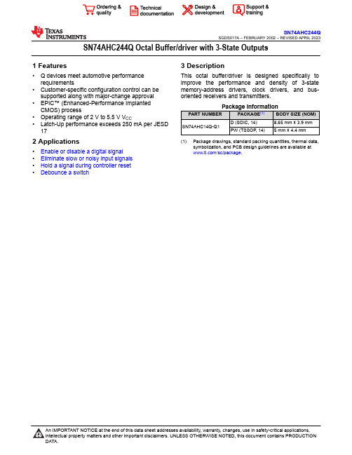
SN74AHC244Q Octal Buffer/driver with 3-State Outputs1 Features•Q devices meet automotive performance requirements•Customer-specific configuration control can be supported along with major-change approval •EPIC™ (Enhanced-Performance Implanted CMOS) process•Operating range of 2 V to 5.5 V V CC•Latch-Up performance exceeds 250 mA per JESD 172 Applications•Enable or disable a digital signal•Eliminate slow or noisy input signals•Hold a signal during controller reset•Debounce a switch 3 DescriptionThis octal buffer/driver is designed specifically to improve the performance and density of 3-state memory-address drivers, clock drivers, and bus-oriented receivers and transmitters.(1)Package drawings, standard packing quantities, thermal data,symbolization, and PCB design guidelines are available at/sc/package.Table of Contents1 Features ............................................................................12 Applications .....................................................................13 Description .......................................................................14 Revision History ..............................................................25 Function Table .................................................................36 Specifications ..................................................................46.1 Absolute Maximum Ratings........................................46.2 ESD Ratings...............................................................46.3 Recommended Operating Conditions.........................46.4 Thermal Information....................................................56.5 Electrical Characteristics.............................................56.6 Switching Characteristics, V CC = 3.3 V ± 0.3 V ..........56.7 Switching Characteristics, V CC = 5 V ± 0.5 V .............66.8 Noise Characteristics..................................................66.9 Operating Characteristics...........................................67 Parameter Measurement Information . (7)8 Detailed Description ........................................................88.1 Overview.....................................................................88.2 Functional Block Diagram...........................................88.3 Device Functional Modes............................................89 Application and Implementation ....................................99.1 Power Supply Recommendations...............................99.2 Layout.........................................................................910 Device and Documentation Support ..........................1110.1 Documentation Support..........................................1110.2 Receiving Notification of Documentation Updates..1110.3 Support Resources.................................................1110.4 Trademarks.............................................................1110.5 Electrostatic Discharge Caution..............................1110.6 Glossary..................................................................1111 Mechanical, Packaging, and OrderableInformation (12)4 Revision HistoryNOTE: Page numbers for previous revisions may differ from page numbers in the current version.Changes from Revision * (February 2002) to Revision A (April 2023)Page •Added Applications , Package Information table, Pin Functions table, ESD Ratings table, Thermal Information table, Device Functional Modes , Application and Implementation section, Power Supply Recommendations section, Layout section, Device and Documentation Support section, and Mechanical, Packaging, andOrderable Information section (1)SN74AHC244QSGDS017A – FEBRUARY 2002 – REVISED APRIL 20235 Function TableFigure 5-1. DW or PW Package (Top View)SN74AHC244QSGDS017A – FEBRUARY 2002 – REVISED APRIL 2023SN74AHC244QSGDS017A – FEBRUARY 2002 – REVISED APRIL 6 Specifications6.1 Absolute Maximum Ratings1.Stresses beyond those listed under “absolute maximum ratings” may cause permanent damage to thedevice. These are stress ratings only, and functional operation of the device at these or any other conditions beyond those indicated under “recommended operating conditions” is not implied. Exposure to absolute-maximum-rated conditions for extended periods may affect device reliability.2.The input and output voltage ratings may be exceeded if the input and output current ratings are observed. 6.2 ESD Ratings(1)JEDEC document JEP155 states that 500-V HBM allows safe manufacturing with a standard ESD control process.(2)JEDEC document JEP157 states that 250-V CDM allows safe manufacturing with a standard ESD control process.6.3 Recommended Operating Conditions(1)(1)(1)All unused inputs of the device must be held at V CC or GND to ensure proper device operation. Refer to the TI application report, Implications of Slow or Floating CMOS Inputs , literature number SCBA004.6.4 Thermal Information(1)For more information about traditional and new thermal metrics, see the IC Package Thermal Metrics application report, SPRA953.6.5 Electrical Characteristics6.6 Switching Characteristics, V CC = 3.3 V ± 0.3 VSN74AHC244QSGDS017A – FEBRUARY 2002 – REVISED APRIL 2023SN74AHC244QSGDS017A – FEBRUARY 2002 – REVISED APRIL 6.7 Switching Characteristics, V CC = 5 V ± 0.5 V6.8 Noise Characteristics(1)(1)Characteristics are for surface-mount packages only.6.9 Operating Characteristics7 Parameter Measurement InformationA.C L includes probe and jig capacitance.B.Waveform 1 is for an output with internal conditions such that the output is low except when disabled by the output control. Waveform 2 is for an output with internal conditions such that the output is high except when disabled by the output control.C.All input pulses are supplied by generators having the following characteristics: PRR ≤ 1 MHz, Z O = 50 Ω, t r ≤ 3 ns, t f ≤ 3 ns.D.The outputs are measured one at a time with one input transition per measurement.Figure 7-1. Load Circuit and Voltage WaveformsSN74AHC244QSGDS017A – FEBRUARY 2002 – REVISED APRIL 20238 Detailed Description8.1 OverviewThe SN74AHC244Q is organized as two 4-bit buffers/line drivers with separate output-enable (OE) inputs. When OE is low, the device passes data from the A inputs to the Y outputs. When OE is high, the outputs are in the high-impedance state.To ensure the high-impedance state during power up or power down, OE should be tied to V CC through a pullup resistor; the minimum value of the resistor is determined by the current-sinking capability of the driver.8.2 Functional Block DiagramFigure 8-1. Logic Diagram (Positive Logic)†Figure 8-2. Logic Symbol8.3 Device Functional Modes†This symbol is in accordance with ANSI/IEEE Std 91-1984 and IEC Publication 617-12.SN74AHC244QSGDS017A – FEBRUARY 2002 – REVISED APRIL 20239 Application and ImplementationNoteInformation in the following applications sections is not part of the TI component specification, and TI does not warrant its accuracy or completeness. TI’s customers are responsible for determining suitability of components for their purposes, as well as validating and testing their design implementation to confirm system functionality.9.1 Power Supply RecommendationsThe power supply can be any voltage between the MIN and MAX supply voltage rating located in the Section 6.3 table.Each VCC pin should have a good bypass capacitor to prevent power disturbance. For devices with a single supply, 0.1 μf is recommended; if there are multiple VCC pins, then 0.01 μf or 0.022 μf is recommended for each power pin. It is acceptable to parallel multiple bypass caps to reject different frequencies of noise. A 0.1 μf and a 1 μf are commonly used in parallel. The bypass capacitor should be installed as close to the power pin as possible for best results.9.2 Layout9.2.1 Layout GuidelinesWhen using multiple-bit logic devices, inputs should never float.In many cases, functions or parts of functions of digital logic devices are unused, for example, when only two inputs of a triple-input AND gate are used or only 3 of the 4 buffer gates are used. Such input pins should not be left unconnected because the undefined voltages at the outside connections result in undefined operational states. Layout Diagram specifies the rules that must be observed under all circumstances. All unused inputs of digital logic devices must be connected to a high or low bias to prevent them from floating. The logic level that should be applied to any particular unused input depends on the function of the device. Generally they will be tied to GND or V CC , whichever makes more sense or is more convenient. It is generally acceptable to float outputs, unless the part is a transceiver. If the transceiver has an output enable pin, it will disable the output section of the part when asserted. This will not disable the input section of the I/Os, so they cannot float when disabled.SN74AHC244QSGDS017A – FEBRUARY 2002 – REVISED APRIL 2023SN74AHC244QSGDS017A – FEBRUARY 2002 – REVISED APRIL 9.2.1.1 Layout ExampleFigure 9-1. Layout Diagram10 Device and Documentation Support10.1 Documentation Support10.1.1 Related DocumentationThe table below lists quick access links. Categories include technical documents, support and community resources, tools and software, and quick access to sample or buy.10.2 Receiving Notification of Documentation UpdatesTo receive notification of documentation updates, navigate to the device product folder on . Click on Subscribe to updates to register and receive a weekly digest of any product information that has changed. For change details, review the revision history included in any revised document.10.3 Support ResourcesTI E2E ™ support forums are an engineer's go-to source for fast, verified answers and design help — straight from the experts. Search existing answers or ask your own question to get the quick design help you need.Linked content is provided "AS IS" by the respective contributors. They do not constitute TI specifications and do not necessarily reflect TI's views; see TI's Terms of Use .10.4 TrademarksTI E2E ™ is a trademark of Texas Instruments.All trademarks are the property of their respective owners.10.5 Electrostatic Discharge CautionThis integrated circuit can be damaged by ESD. Texas Instruments recommends that all integrated circuits be handled with appropriate precautions. Failure to observe proper handling and installation procedures can cause damage.ESD damage can range from subtle performance degradation to complete device failure. Precision integrated circuits may be more susceptible to damage because very small parametric changes could cause the device not to meet its published specifications.10.6 GlossaryTI GlossaryThis glossary lists and explains terms, acronyms, and definitions.SN74AHC244QSGDS017A – FEBRUARY 2002 – REVISED APRIL 2023SN74AHC244QSGDS017A – FEBRUARY 2002 – REVISED APRIL 11 Mechanical, Packaging, and Orderable InformationThe following pages include mechanical, packaging, and orderable information. This information is the most current data available for the designated devices. This data is subject to change without notice and revision of this document. For browser-based versions of this data sheet, refer to the left-hand navigation.PACKAGING INFORMATION(1) The marketing status values are defined as follows:ACTIVE: Product device recommended for new designs.LIFEBUY: TI has announced that the device will be discontinued, and a lifetime-buy period is in effect.NRND: Not recommended for new designs. Device is in production to support existing customers, but TI does not recommend using this part in a new design.PREVIEW: Device has been announced but is not in production. Samples may or may not be available.OBSOLETE: TI has discontinued the production of the device.(2) RoHS: TI defines "RoHS" to mean semiconductor products that are compliant with the current EU RoHS requirements for all 10 RoHS substances, including the requirement that RoHS substance do not exceed 0.1% by weight in homogeneous materials. Where designed to be soldered at high temperatures, "RoHS" products are suitable for use in specified lead-free processes. TI may reference these types of products as "Pb-Free".RoHS Exempt: TI defines "RoHS Exempt" to mean products that contain lead but are compliant with EU RoHS pursuant to a specific EU RoHS exemption.Green: TI defines "Green" to mean the content of Chlorine (Cl) and Bromine (Br) based flame retardants meet JS709B low halogen requirements of <=1000ppm threshold. Antimony trioxide based flame retardants must also meet the <=1000ppm threshold requirement.(3) MSL, Peak Temp. - The Moisture Sensitivity Level rating according to the JEDEC industry standard classifications, and peak solder temperature.(4) There may be additional marking, which relates to the logo, the lot trace code information, or the environmental category on the device.(5) Multiple Device Markings will be inside parentheses. Only one Device Marking contained in parentheses and separated by a "~" will appear on a device. If a line is indented then it is a continuation of the previous line and the two combined represent the entire Device Marking for that device.(6) Lead finish/Ball material - Orderable Devices may have multiple material finish options. Finish options are separated by a vertical ruled line. Lead finish/Ball material values may wrap to two lines if the finish value exceeds the maximum column width.Important Information and Disclaimer:The information provided on this page represents TI's knowledge and belief as of the date that it is provided. TI bases its knowledge and belief on information provided by third parties, and makes no representation or warranty as to the accuracy of such information. Efforts are underway to better integrate information from third parties. TI has taken andAddendum-Page 1continues to take reasonable steps to provide representative and accurate information but may not have conducted destructive testing or chemical analysis on incoming materials and chemicals. TI and TI suppliers consider certain information to be proprietary, and thus CAS numbers and other limited information may not be available for release.In no event shall TI's liability arising out of such information exceed the total purchase price of the TI part(s) at issue in this document sold by TI to Customer on an annual basis.Addendum-Page 2TAPE AND REEL INFORMATIONA0B0K0W Dimension designed to accommodate the component length Dimension designed to accommodate the component thickness Overall width of the carrier tapePitch between successive cavity centersDimension designed to accommodate the component width TAPE DIMENSIONSSprocket HolesP1*All dimensions are nominalDevicePackage Type Package Drawing Pins SPQReel Diameter (mm)Reel Width W1 (mm)A0(mm)B0(mm)K0(mm)P1(mm)W (mm)Pin1Quadrant SN74AHC244QDWRG4SOIC DW 202000330.024.410.813.3 2.712.024.0Q1SN74AHC244QDWRG4Q1SOIC DW 202000330.024.410.813.3 2.712.024.0Q1SN74AHC244QPWR TSSOP PW 202000330.016.4 6.957.0 1.48.016.0Q1SN74AHC244QPWRG4TSSOPPW202000330.016.46.957.01.48.016.0Q1*All dimensions are nominalDevice Package Type Package Drawing Pins SPQ Length (mm)Width (mm)Height (mm) SN74AHC244QDWRG4SOIC DW202000367.0367.045.0SN74AHC244QDWRG4Q1SOIC DW202000367.0367.045.0 SN74AHC244QPWR TSSOP PW202000356.0356.035.0SN74AHC244QPWRG4TSSOP PW202000356.0356.035.0PACKAGE OUTLINESOIC - 2.65 mm max heightDW0020ASOICNOTES:1. All linear dimensions are in millimeters. Dimensions in parenthesis are for reference only. Dimensioning and tolerancing per ASME Y14.5M.2. This drawing is subject to change without notice.3. This dimension does not include mold flash, protrusions, or gate burrs. Mold flash, protrusions, or gate burrs shall not exceed 0.15 mm per side.4. This dimension does not include interlead flash. Interlead flash shall not exceed 0.43 mm per side.5. Reference JEDEC registration MS-013.EXAMPLE BOARD LAYOUT DW0020ASOIC - 2.65 mm max heightSOIC ArrayNOTES: (continued)6. Publication IPC-7351 may have alternate designs.7. Solder mask tolerances between and around signal pads can vary based on board fabrication site.EXAMPLE STENCIL DESIGN DW0020ASOIC - 2.65 mm max heightSOIC ArrayNOTES: (continued)8. Laser cutting apertures with trapezoidal walls and rounded corners may offer better paste release. IPC-7525 may have alternatedesign recommendations.9. Board assembly site may have different recommendations for stencil design.PACKAGE OUTLINETSSOP - 1.2 mm max heightPW0020ASMALL OUTLINE PACKAGENOTES:1. All linear dimensions are in millimeters. Any dimensions in parenthesis are for reference only. Dimensioning and tolerancing per ASME Y14.5M.2. This drawing is subject to change without notice.3. This dimension does not include mold flash, protrusions, or gate burrs. Mold flash, protrusions, or gate burrs shall not exceed 0.15 mm per side.4. This dimension does not include interlead flash. Interlead flash shall not exceed 0.25 mm per side.5. Reference JEDEC registration MO-153.EXAMPLE BOARD LAYOUTTSSOP - 1.2 mm max heightPW0020A SMALL OUTLINE PACKAGENOTES: (continued)6. Publication IPC-7351 may have alternate designs.7. Solder mask tolerances between and around signal pads can vary based on board fabrication site.EXAMPLE STENCIL DESIGNTSSOP - 1.2 mm max heightPW0020A SMALL OUTLINE PACKAGENOTES: (continued)8. Laser cutting apertures with trapezoidal walls and rounded corners may offer better paste release. IPC-7525 may have alternate design recommendations.9. Board assembly site may have different recommendations for stencil design.IMPORTANT NOTICE AND DISCLAIMERTI PROVIDES TECHNICAL AND RELIABILITY DATA (INCLUDING DATA SHEETS), DESIGN RESOURCES (INCLUDING REFERENCE DESIGNS), APPLICATION OR OTHER DESIGN ADVICE, WEB TOOLS, SAFETY INFORMATION, AND OTHER RESOURCES “AS IS” AND WITH ALL FAULTS, AND DISCLAIMS ALL WARRANTIES, EXPRESS AND IMPLIED, INCLUDING WITHOUT LIMITATION ANY IMPLIED WARRANTIES OF MERCHANTABILITY, FITNESS FOR A PARTICULAR PURPOSE OR NON-INFRINGEMENT OF THIRD PARTY INTELLECTUAL PROPERTY RIGHTS.These resources are intended for skilled developers designing with TI products. You are solely responsible for (1) selecting the appropriate TI products for your application, (2) designing, validating and testing your application, and (3) ensuring your application meets applicable standards, and any other safety, security, regulatory or other requirements.These resources are subject to change without notice. TI grants you permission to use these resources only for development of an application that uses the TI products described in the resource. Other reproduction and display of these resources is prohibited. No license is granted to any other TI intellectual property right or to any third party intellectual property right. TI disclaims responsibility for, and you will fully indemnify TI and its representatives against, any claims, damages, costs, losses, and liabilities arising out of your use of these resources.TI’s products are provided subject to TI’s Terms of Sale or other applicable terms available either on or provided in conjunction with such TI products. TI’s provision of these resources does not expand or otherwise alter TI’s applicable warranties or warranty disclaimers for TI products.TI objects to and rejects any additional or different terms you may have proposed.Mailing Address: Texas Instruments, Post Office Box 655303, Dallas, Texas 75265Copyright © 2023, Texas Instruments Incorporated。
SFH484中文资料

Features q Fabricated in a liquid phase epitaxy process q High reliability q Spectral match with silicon photodetectors q SFH 484: Same package as LD 274 q SFH 485: Same package as SFH 300,
1.5
29 27
4.8 4.2
Chip position
0.6 0.4
GEX06305
fex06305
Approx. weight 0.5 g Maße in mm, wenn nicht anders angegeben/Dimensions in mm, unless otherwise specified.
40
30
20
10
0
ϕ
1.0
50
0.8
OHR01891
60
0.6
70
0.4
80
0.2
90
0
100
1.0 0.8 0.6
0.4
0 20 40 60 80 100 120
Semiconductor Group
4
1997-11-01
SFH 484 SFH 485
Relative spectral emission Irel = f (λ)
Sperrspannung Reverse voltage
Durchlaßstrom Forward current
Stoßstrom, tp = 10 µs, D = 0
Surge current
Verlustleistung Power dissipation
74LS244中文资料
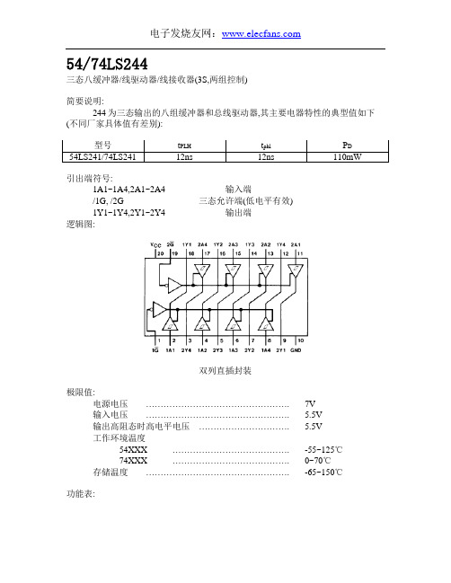
54/74LS244三态八缓冲器/线驱动器/线接收器(3S,两组控制)简要说明:244为三态输出的八组缓冲器和总线驱动器,其主要电器特性的典型值如下(不同厂家具体值有差别):型号t PLH t phl P D54LS241/74LS241 12ns 12ns 110mW引出端符号:1A1~1A4,2A1~2A4 输入端/1G, /2G 三态允许端(低电平有效)1Y1~1Y4,2Y1~2Y4 输出端逻辑图:双列直插封装极限值:电源电压 (7V)输入电压…………………………………………. 5.5V输出高阻态时高电平电压…………………………. 5.5V工作环境温度54XXX …………………………………. -55~125℃74XXX …………………………………. 0~70℃存储温度…………………………………………. -65~150℃功能表:推荐工作条件:54LS244/74LS244单位最小额定最大电源电压Vcc 54 4.5 5 5.5V 74 4.75 5 5.25输入高电平电V iH 2 V输入低电平电V iL 54 0.7V 74 0.8输出高电平电流I OH 54 -12mA 74 -15输出低电平电流I OL 54 12mA 74 24动态特性(T A=25℃)参数测试条件LS244单位最大t PLH输出由低到高传输延迟时间Vcc =5VC L=45pFR L=667 Ω18 nst PHL输出由高到低传输延迟时间18 ns t PZH输出由高阻态到高允许时间23 ns t PZL输出由高阻态到低允许时间30 nst PHZ输出由高到高阻态禁止时间Vcc=5V C L=5pFR L=90 Ω18 nst PLZ输出由低到高阻态禁止时间25 ns 静态特性(TA为工作环境温度范围)参数测试条件【1】LS244单位最小最大V IK输入嵌位电压Vcc=最小,I ik=-18mA -1.5 V △V T滞后电压Vcc=最小0.2 VV OH输出高电平电压Vcc=最小,V IL=最大,V IH=2V,I OH=-3mA2.4 VV OL输出低电平电压Vcc=最小,V IL=最大, I OL=最大54 0.4V74 0.5[1]: 测试条件中的“最小”和“最大”用推荐工作条件中的相应值。
SIHFIZ44G中文资料

Power MOSFETIRFIZ44G, SiHFIZ44GVishay SiliconixFEATURES•Isolated Package•H igh Voltage Isolation = 2.5 kV RMS (t = 60 s;f = 60 Hz)•Sink to Lead Creepage Distance = 4.8 mm •175 °C Operating Temperature •Dynamic dV/dt Rating •Low Thermal Resistance •Lead (Pb)-free AvailableDESCRIPTIONThird generation Power MOSFETs from Vishay provide the designer with the best combination of fast switching,ruggedized device design, low on-resistance and cost-effectiveness.The TO-220 FULLPAK eliminates the need for additional insulating hardware in commercial-industrial applications.The molding compound used provides a high isolation capability and a low thermal resistance between the tab and external heatsink. The isolation is equivalent to using a 100micron mica barrier with standard TO-220 product. The FULLPAK is mounted to a heatsink using a single clip or by a single screw fixing.Notesa.Repetitive rating; pulse width limited by maximum junction temperature (see fig. 11).b.V DD = 25 V, starting T J = 25 °C, L = 129 µH, R G = 25 Ω, I AS = 30 A (see fig. 12).c.I SD ≤ 52 A, dI/dt ≤ 250 A/µs, V DD ≤ V DS , T J ≤ 175 °C.d. 1.6 mm from case.PRODUCT SUMMARYV DS (V)60R DS(on) (Ω)V GS = 10 V0.028Q g (Max.) (nC)95Q gs (nC)27Q gd (nC)46ConfigurationSingleORDERING INFORMATIONPackage TO-220 FULLPAK Lead (Pb)-free IRFIZ44GPbF SiHFIZ44G-E3SnPbIRFIZ44G SiHFIZ44GABSOLUTE MAXIMUM RATINGS T C = 25 °C, unless otherwise notedPARAMETER SYMB O L LIMITUNITDrain-Source Voltage V DS 60VGate-Source Voltage V GS ± 20 Continuous Drain CurrentV GS at 10 VT C = 25 °C I D30A T C = 100 °C21Pulsed Drain Current a I DM 120Linear Derating Factor0.32W/°CSingle Pulse Avalanche Energy b E AS 100mJ Maximum Power Dissipation T C = 25 °CP D 48W Peak Diode Recovery dV/dt cdV/dt 4.5V/ns Operating Junction and Storage Temperature Range T J , T stg - 55 to + 175°CSoldering Recommendations (Peak Temperature)for 10 s 300d Mounting Torque6-32 or M3 screw10 lbf · in 1.1N · m* Pb containing terminations are not RoHS compliant, exemptions may applyIRFIZ44G, SiHFIZ44GVishay SiliconixNotesa.Repetitive rating; pulse width limited by maximum junction temperature (see fig. 11).b.Pulse width ≤ 300 µs; duty cycle ≤ 2 %.THERMAL RESISTANCE RATINGSPARAMETER SYMBL TYP.MAX.UNIT Maximum Junction-to-Ambient R thJA -65°C/WMaximum Junction-to-Case (Drain)R thJC- 3.1IRFIZ44G, SiHFIZ44GVishay SiliconixFig. 2 - Typical Output Characteristics, T C = 175 °C Fig. 4 - Normalized On-Resistance vs. TemperatureIRFIZ44G, SiHFIZ44GVishay SiliconixFig. 9 - Maximum Drain Current vs. Case Temperature Fig. 10a - Switching Time Test Circuit Fig. 10b - Switching Time WaveformsFig. 12b - Unclamped Inductive WaveformsIRFIZ44G, SiHFIZ44GVishay SiliconixFig. 13a - Basic Gate Charge WaveformFig. 13b - Gate Charge Test CircuitIRFIZ44G, SiHFIZ44GVishay Siliconix Array Fig. 14 - For N-ChannelVishay Siliconix maintains worldwide manufacturing capability. Products may be manufactured at one of several qualified locations. Reliability data for Silicon Technology and Package Reliability represent a composite of all qualified locations. For related documents such as package/tape drawings, part marking, andreliability data, see /ppg?91189.Disclaimer Legal Disclaimer NoticeVishayAll product specifications and data are subject to change without notice.Vishay Intertechnology, Inc., its affiliates, agents, and employees, and all persons acting on its or their behalf (collectively, “Vishay”), disclaim any and all liability for any errors, inaccuracies or incompleteness contained herein or in any other disclosure relating to any product.Vishay disclaims any and all liability arising out of the use or application of any product described herein or of any information provided herein to the maximum extent permitted by law. The product specifications do not expand or otherwise modify Vishay’s terms and conditions of purchase, including but not limited to the warranty expressed therein, which apply to these products.No license, express or implied, by estoppel or otherwise, to any intellectual property rights is granted by this document or by any conduct of Vishay.The products shown herein are not designed for use in medical, life-saving, or life-sustaining applications unless otherwise expressly indicated. Customers using or selling Vishay products not expressly indicated for use in such applications do so entirely at their own risk and agree to fully indemnify Vishay for any damages arising or resulting from such use or sale. Please contact authorized Vishay personnel to obtain written terms and conditions regarding products designed for such applications.Product names and markings noted herein may be trademarks of their respective owners.元器件交易网。
74系列芯片数据手册大全
74系列芯片数据手册大全74系列集成电路名称与功能常用74系列标准数字电路的中文名称资料7400 TTL四2输入端四与非门7401 TTL 集电极开路2输入端四与非门7402 TTL 2输入端四或非门7403 TTL 集电极开路2输入端四与非门7404 TTL 六反相器7405 TTL 集电极开路六反相器7406 TTL 集电极开路六反相高压驱动器7407 TTL 集电极开路六正相高压缓冲驱动器7408 TTL 2输入端四与门7409 TTL 集电极开路2输入端四与门7410 TTL 3输入端3与非门74107 TTL 带清除主从双J-K触发器74109 TTL 带预置清除正触发双J-K触发器7411 TTL 3输入端3与门74112 TTL 带预置清除负触发双J-K触发器7412 TTL 开路输出3输入端三与非门74121 TTL 单稳态多谐振荡器74122 TTL 可再触发单稳态多谐振荡器74123 TTL 双可再触发单稳态多谐振荡器74125 TTL 三态输出高有效四总线缓冲门74126 TTL 三态输出低有效四总线缓冲门7413 TTL 4输入端双与非施密特触发器74132 TTL 2输入端四与非施密特触发器74133 TTL 13输入端与非门74136 TTL 四异或门74138 TTL 3-8线译码器/复工器74139 TTL 双2-4线译码器/复工器7414 TTL 六反相施密特触发器74145 TTL BCD—十进制译码/驱动器7415 TTL 开路输出3输入端三与门74150 TTL 16选1数据选择/多路开关74151 TTL 8选1数据选择器74153 TTL 双4选1数据选择器74154 TTL 4线—16线译码器74155 TTL 图腾柱输出译码器/分配器74156 TTL 开路输出译码器/分配器74157 TTL 同相输出四2选1数据选择器74158 TTL 反相输出四2选1数据选择器7416 TTL 开路输出六反相缓冲/驱动器74160 TTL 可预置BCD异步清除计数器74161 TTL 可予制四位二进制异步清除计数器74162 TTL 可预置BCD同步清除计数器74163 TTL 可予制四位二进制同步清除计数器74164 TTL 八位串行入/并行输出移位寄存器74165 TTL 八位并行入/串行输出移位寄存器74166 TTL 八位并入/串出移位寄存器74169 TTL 二进制四位加/减同步计数器7417 TTL 开路输出六同相高压缓冲/驱动器74170 TTL 开路输出4×4寄存器堆74173 TTL 三态输出四位D型寄存器74174TTL 带公共时钟和复位六D触发器74175 TTL 带公共时钟和复位四D触发器74180 TTL 9位奇数/偶数发生器/校验器74181 TTL 算术逻辑单元/函数发生器74185 TTL 二进制—BCD代码转换器74190 TTL BCD同步加/减计数器74191 TTL 二进制同步可逆计数器74192 TTL 可预置BCD双时钟可逆计数器74193 TTL 可预置四位二进制双时钟可逆计数器74194 TTL 四位双向通用移位寄存器74195 TTL 四位并行通道移位寄存器74196 TTL 十进制/二-十进制可预置计数锁存器74197 TTL 二进制可预置锁存器/计数器7420 TTL 4输入端双与非门7421 TTL 4输入端双与门7422 TTL 开路输出4输入端双与非门74221 TTL 双/单稳态多谐振荡器74240 TTL 八反相三态缓冲器/线驱动器74241 TTL 八同相三态缓冲器/线驱动器74243 TTL 四同相三态总线收发器74244 TTL 八同相三态缓冲器/线驱动器74245 TTL 八同相三态总线收发器74247 TTL BCD—7段15V输出译码/驱动器74248 TTL BCD—7段译码/升压输出驱动器74249 TTL BCD—7段译码/开路输出驱动器7425 双4输入端或非门(有选通端74251 TTL 三态输出8选1数据选择器/复工器74253 TTL 三态输出双4选1数据选择器/复工器74256 TTL 双四位可寻址锁存器74257 TTL 三态原码四2选1数据选择器/复工器74258 TTL 三态反码四2选1数据选择器/复工器74259 TTL 八位可寻址锁存器/3-8线译码器7426 TTL 2输入端高压接口四与非门缓冲器74260 TTL 5输入端双或非门74266 TTL 2输入端四异或非门7427 TTL 3输入端三或非门74273 TTL 带公共时钟复位八D触发器74279 TTL 四图腾柱输出S-R锁存器7428 TTL 2输入端四或非门缓冲器74283 TTL 4位二进制全加器74290 TTL 二/五分频十进制计数器74293 TTL 二/八分频四位二进制计数器74295 TTL 四位双向通用移位寄存器74298 TTL 四2输入多路带存贮开关74299 TTL 三态输出八位通用移位寄存器7430 TTL 8输入端与非门7432 TTL 2输入端四或门74322 TTL 带符号扩展端八位移位寄存器74323 TTL 三态输出八位双向移位/存贮寄存器7433 TTL 开路输出2输入端四或非缓冲器74347 TTL BCD—7段译码器/驱动器74352 TTL 双4选1数据选择器/复工器74353 TTL 三态输出双4选1数据选择器/复工器74365 TTL 门使能输入三态输出六同相线驱动器74365 TTL 门使能输入三态输出六同相线驱动器74366 TTL 门使能输入三态输出六反相线驱动器74367 TTL 4/2线使能输入三态六同相线驱动器74368 TTL 4/2线使能输入三态六反相线驱动器7437 TTL 开路输出2输入端四与非缓冲器74373 TTL 三态同相八D锁存器74374TTL 三态反相八D锁存器74375 TTL 4位双稳态锁存器74377 TTL 单边输出公共使能八D锁存器74378 TTL 单边输出公共使能六D锁存器74379 TTL 双边输出公共使能四D锁存器7438 TTL 开路输出2输入端四与非缓冲器74380 TTL 多功能八进制寄存器7439 TTL 开路输出2输入端四与非缓冲器74390 TTL 双十进制计数器74393 TTL 双四位二进制计数器7440 TTL 4输入端双与非缓冲器7442 TTL BCD—十进制代码转换器7443 4线-10线译码器(余3码输入)7444 4线-10线译码器(余3葛莱码输入) 74447 TTL BCD—7段译码器/驱动器7445 TTL BCD—十进制代码转换/驱动器74450 TTL 16:1多路转接复用器多工器74451 TTL 双8:1多路转接复用器多工器74453 TTL 四4:1多路转接复用器多工器7446 TTL BCD—7段低有效译码/驱动器74460 TTL 十位比较器74461 TTL 八进制计数器74465 TTL 三态同相2与使能端八总线缓冲器74466 TTL 三态反相2与使能八总线缓冲器74467 TTL 三态同相2使能端八总线缓冲器74468 TTL 三态反相2使能端八总线缓冲器74469 TTL 八位双向计数器7447 TTL BCD—7段高有效译码/驱动器7448 TTL BCD—7段译码器/内部上拉输出驱动7449 4线-7段译码器74490 TTL 双十进制计数器74491 TTL 十位计数器74498 TTL 八进制移位寄存器7450 TTL 2-3/2-2输入端双与或非门74502 TTL 八位逐次逼近寄存器74503 TTL 八位逐次逼近寄存器7451 TTL 2-3/2-2输入端双与或非门7452 4路2-3-2-2输入与或门7453 4路2-2-2-2输入与或非门74533 TTL 三态反相八D锁存器74534 TTL 三态反相八D锁存器7454 TTL 四路输入与或非门74540 TTL 八位三态反相输出总线缓冲器7455 TTL 4输入端二路输入与或非门74563 TTL 八位三态反相输出触发器74564 TTL 八位三态反相输出D触发器74573 TTL 八位三态输出触发器74574TTL 八位三态输出D触发器7460 双4输入与扩展器7461 三3输入与扩展器7462 4路2-3-3-2输入与或扩展器7464 4路4-2-3-2输入与或非门74645 TTL 三态输出八同相总线传送接收器7465 4路4-2-3-2输入与或非门(OC)74670 TTL 三态输出4×4寄存器堆7470 与门输入J-K触发器√7471 与或门输入J-K触发器√7472 与门输入J-K触发器7473 TTL 带清除负触发双J-K触发器7474 TTL 带置位复位正触发双上升沿D触发器7476 TTL 带预置清除双J-K触发器7478 双D型触发器7483 TTL 四位二进制快速进位全加器7485 TTL 四位数字比较器7486 TTL 2输入端四异或门7487 4位二进制原码/反码7490 TTL 可二/五分频十进制计数器7493 TTL 可二/八分频二进制计数器7495 TTL 四位并行输入\输出移位寄存器7497 TTL 6位同步二进制乘法器74101 与或门输入J-K触发器74102 与门输入J-K触发器74107 双主-从J-K触发器74108 双主-从J-K触发器74109 双主-从J-K触发器74110 与门输入J-K触发器74111 双主-从J-K触发器74112 双下降沿J-K触发器74113 双下降沿J-K触发器74114 双下降沿J-K触发器74116 双4位锁存器74120 双脉冲同步驱动器74121 单稳态触发器74122 可重触发单稳态触发器74123 可重触发双稳态触发器74125 四总线缓冲器74126 四总线缓冲器74128 四2输入端或非线驱动器74132 四2输入端与非门友情提示:本资料代表个人观点,如有帮助请下载,谢谢您的浏览!。
GR47-48中文技术手册
GR47/GR48技术说明书Sony Ericssonwww.usstinfo.com1 引言1.1 概述GR47/GR48 是属于 Sony Ericsson 新一代的移动通信 GSM 模块。
本文分别描述900/1800 MHz 和 850/1900 MHz 双波段 GSM 产品 GR47/48 的主要特征和功能。
它们预期使用在机机(machine-to-machine)和人机(man-to-machine)应用中,适合需要发送和接收数据(SMS, CSD, HSCSD, GPRS)的地方,也可以通过 GSM 网络语音呼叫。
GR47/GR48 模块是商业到商业(business-to-business)产品,预期对象是生产商、系统集成商、应用开发者的无线通信解决方案。
模块预期集成到系统集成商的应用内,和构成无线通信系统外部应用。
外部应用的一个典型系统是模块通过串行接口与微处理器通信。
微处理器控制模块,借助于 AT 命令支持完成。
设想系统集成商有高技术知识和能力把模块集成进系统。
以下是GR47/GR48 模块一些有用的应用。
• 车队和财物管理。
• 自动售货机。
• 安全与报警。
• 其它遥感勘测应用。
1.2 特点模块完成电信服务 (TS) 按照 GSM 标准 2+,ETSI 和 ITU-T。
模块功能由 AT 命令通过串行接口实现。
支持第 5 节列出的 AT 命令,更多的定义在 GSM 7.05/7.07 和GR47/GR48 的综合手册里。
1.2.1 移动站类型GR4X 家属是常规的双波段 MS 类型,有下列特性。
GR47GSM 900E-GSM 900GSM 1800频率范围(MHz)TX: 880-915RX: 935-960TX: 880-890RX: 925-935TX: 1710-1785RX: 1805-1880频道间隔200 kHz200 kHz频道号173 载波 *8 (TDMA)GSM: 频道1 - 124E-GSM: 频道975 - 1023374 载波 *8 (TDMA)DCS: 频道512 - 885调制GMSK GMSKTX 相位精度< 5º RMS 相位误差(脉冲) < 5º RMS 相位误差(脉冲) 双向间隔45 MHz 95 MHz有天线接收灵敏度< - 102 dBm < - 102 dBm有天线发射机输出功率 4 类 2W (33 dBm) 1 类 1W (30 dBm)GSM 900 与 GSM 1800 之间自动变换2GR48GSM 850GSM 1900频率范围TX: 824-849RX: 869-894TX: 1850-1910RX: 1930-1990频道间隔200 kHz200 kHz频道号123 carriers *8 (TDMA) 载波GSM: Channels 128 to 251298 Carriers *8 (TDMA)PCS: Channels 512 to 810调制GMSK GMSKTX 相位精度< 5º RMS 相位误差(脉冲)< 5º RMS 相位误差(脉冲)双向间隔45 MHz80 MHz有天线接收灵敏度< - 102 dBm< - 102 dBm有天线发射机输出功率 5 类0.8 W (29 dBm) 1 类 1W (30 dBm)GSM 850 和 GSM 1900 之间自动变换1.2.2 SMS模块支持下列 SMS 服务:• 发送:MO,支持双 PDU 和文本模式。
MAX4844中文资料

General DescriptionThe MAX4843–MAX4846 overvoltage protection con-trollers protect low-voltage systems against high-voltage faults of up to 28V. When the input voltage exceeds the overvoltage threshold, these devices turn off a low-cost,external n-channel FET(s) to prevent damage to the pro-tected components. An internal charge pump eliminates the need for external capacitors and drives the FET gate for a simple, robust solution.The overvoltage trip level is set to 7.4V (MAX4843),6.35V (MAX4844), 5.8V (MAX4845), or 4.65V (MAX4846). When the input voltage drops below the undervoltage lockout (UVLO) threshold, the devices enter a low standby current mode (10µA). The MAX4843/MAX4844/ MAX4845 have a UVLO threshold of 4.15V, and the MAX4846 has a UVLO threshold of 2.5V. In addition to the single FET configuration, the devices can be configured with back-to-back external FETs to prevent currents from being back-driven into the adapter.An additional feature includes a ±15kV ESD-protected input when bypassed with a 1µF capacitor to ground. All devices are offered in a small (1.5mm x 1.0mm) 6-pin µDFN package and are specified for operation over the -40°C to +85°C temperature range.ApplicationsCell Phones Digital Still Cameras PDAs and Palmtop Devices MP3 PlayersFeatureso Overvoltage Protection Up to 28Vo Preset 7.4V, 6.35V, 5.8V, or 4.65V Overvoltage Trip Levelo Low (10µA) Undervoltage Lockout Standby Currento Drives Low-Cost n MOSFET o Internal 50ms Startup Delay o Internal Charge Pumpo Overvoltage Fault FLAG Indicatoro6-Pin (1.5mm x 1.0mm) µDFN PackageMAX4843–MAX4846Overvoltage Protection Controllers withLow Standby Current________________________________________________________________Maxim Integrated Products 1Pin ConfigurationTypical Operating Circuit19-3649; Rev 0; 4/05For pricing, delivery, and ordering information,please contact Maxim/Dallas Direct!at 1-888-629-4642, or visit Maxim’s website at .range.M A X 4843–M A X 4846Overvoltage Protection Controllers with Low Standby Current 2_______________________________________________________________________________________ABSOLUTE MAXIMUM RATINGSELECTRICAL CHARACTERISTICS(V IN = +5V for MAX4843/MAX4844/MAX4845, V IN = +4V for MAX4846, C GATE = 500pF, T A = -40°C to +85°C, unless otherwiseStresses beyond those listed under “Absolute Maximum Ratings” may cause permanent damage to the device. These are stress ratings only, and functional operation of the device at these or any other conditions beyond those indicated in the operational sections of the specifications is not implied. Exposure to absolute maximum rating conditions for extended periods may affect device reliability.IN to GND ..............................................................-0.3V to +30V GATE to GND ........................................................-0.3V to +12V FLAG to GND ..........................................................-0.3V to +6V Continuous Power Dissipation (T A = +70°C)6-Pin µDFN (derate 2.1mW/°C above +70°C) .........167.7mWOperating Temperature Range ..........................-40°C to +85°C Junction Temperature ....................................................+150°C Storage Temperature Range ............................-65°C to +150°C Lead Temperature (soldering, 10s) ................................+300°CMAX4843–MAX4846Overvoltage Protection Controllers withLow Standby Current_______________________________________________________________________________________3ELECTRICAL CHARACTERISTICS (continued)(V IN = +5V for MAX4843/MAX4844/MAX4845, V IN = +4V for MAX4846, C GATE = 500pF, T A = -40°C to +85°C, unless otherwise Typical Operating Characteristics(V IN = +5V for MAX4843/MAX4844/MAX4845, V IN = +4V for MAX4846, T A = +25°C, unless otherwise noted.)SUPPLY CURRENT vs. SUPPLY VOLTAGE(MAX4843)M A X 4843-46 t o c 01SUPPLY VOLTAGE (V)S U P P L Y C U R R E N T (µA )252015105204060801000030REVERSE CURRENT vs. OUTPUT VOLTAGE(MAX4843)OUTPUT VOLTAGE (V)R E V E R S E C U R R E N T (µA )7645320.000010.00010.0010.010.111010010000.0000011GATE VOLTAGE vs. INPUT VOLTAGE (MAX4843/MAX4844/MAX4845)INPUT VOLTAGE (V)G A T E V O L T A G E (V )76543691215038M A X 4843–M A X 4846Overvoltage Protection Controllers with Low Standby CurrentTypical Operating Characteristics (continued)(V IN = +5V for MAX4843/MAX4844/MAX4845, V IN = +4V for MAX4846, T A = +25°C, unless otherwise noted.)GATE VOLTAGE vs. INPUT VOLTAGE(MAX4846)M A X 4843-46 t o c 04INPUT VOLTAGE (V)G A T E V O L T A G E (V )5432246810016GATE VOLTAGE vs. INPUT VOLTAGE(MAX4843)INPUT VOLTAGE (V)G A T E V O L T A G E (V )76549.7510.0010.2510.509.5038POWER-UP RESPONSEMAX4843-46 toc0620ms/DIV5V/DIVV INV GATEV FLAG5V/DIV5V/DIVPOWER-UP RESPONSEMAX4843-46 toc0720ms/DIV5V/DIVV INV OUTI INV FLAG5V/DIV 01A/DIV5V/DIV 0OVERVOLTAGE RESPONSEMAX4843-46 toc084µs/DIV5V/DIVV INV GATEI GATEV FLAG10V/DIV08V10mA/DIV05V/DIVPOWER-UP OVERVOLTAGE RESPONSEMAX4843-46 toc0920µs/DIV5V/DIVV INV GATEV FLAG2V/DIV 08V 05V/DIVMAX4843–MAX4846Overvoltage Protection Controllers withLow Standby Current_______________________________________________________________________________________5Functional DiagramFigure 2. Shutdown Timing DiagramFigure 1. Startup Timing Diagram Figure 3. Power-Up Overvoltage Timing DiagramM A X 4843–M A X 4846Overvoltage Protection Controllers with Low Standby Current 6_______________________________________________________________________________________Detailed DescriptionThe MAX4843–MAX4846 provide up to 28V overvoltage protection for low-voltage systems. When the input volt-age exceeds the overvoltage trip level, the MAX4843–MAX4846 turn off a low-cost external n-chan-nel FET(s) to prevent damage to the protected compo-nents. An internal charge pump (see the Functional Diagram ) drives the FET gate for a simple, robust solu-tion. On power-up, the device waits for 50ms before dri-ving GATE high. The open-drain FLAG output is kept at high impedance for an additional 50ms after GATE goes high before deasserting. The FLAG output asserts high immediately to an overvoltage fault.Undervoltage Lockout (UVLO)The MAX4843/MAX4844/MAX4845 have a fixed 4.15V typical UVLO level, while the MAX4846 has a 2.5V typi-cal UVLO. When V IN is less than the UVLO, the GATE driver is held low and FLAG is asserted.Overvoltage Lockout (OVLO)The MAX4843 has a 7.4V typical OVLO; the MAX4844has a 6.35V typical OVLO; and the MAX4845 has a 5.8V typical OVLO. The MAX4846 has a 4.65V typical overvoltage threshold. When V IN is greater than OVLO,the GATE driver is held low and FLAG is asserted.FLAG OutputThe open-drain FLAG output is used to signal to the host system that there is a fault with the input voltage.FLAG asserts immediately to an overvoltage fault.FLAG is held high for 50ms after GATE turns on before deasserting. Connect a pullup resistor from FLAG to the logic I/O voltage of the host system.GATE DriverAn on-chip charge pump is used to drive GATE above IN, allowing the use of low-cost n-channel MOSFETs. The charge pump operates from the internal 5.5V regulator.The actual GATE output voltage tracks approximately two times V IN until V IN exceeds 5.5V or the OVLO trip level is exceeded, whichever comes first. The MAX4843 has a 7.4V typical OVLO, therefore GATE remains relatively constant at about 10.5V for 5.5V <V IN < 7.4V. The MAX4845 has a 5.8V typical OVLO, but this can be as low as 5.5V. The GATE output voltage as a function of input voltage is shown in the Typical Operating Characteristics .Device OperationThe MAX4843–MAX4846 have an on-board state machine to control device operation. A flowchart is shown in Figure 4. On initial power-up, if V IN < UVLO or if V IN > OVLO, GATE is held at 0V, and FLAG is high.If UVLO < V IN < OVLO, the device enters startup after a 50ms internal delay. The internal charge pump is enabled, and GATE begins to be driven above V IN by the internal charge pump. FLAG is held high during startup until the FLAG blanking period expires, typically 50ms after the GATE starts going high. At this point the device is in its on state.At any time if V IN drops below UVLO or V IN is greater than OVLO, FLAG is driven high and GATE is driven to ground.Figure 4. State DiagramApplications InformationMOSFET ConfigurationThe MAX4843–MAX4846 can be used with either a sin-gle MOSFET configuration as shown in the Typical Operating Circuit , or can be configured with a back-to-back MOSFET as shown in Figure 5. The back-to-back configuration has almost zero reverse current when the input supply is below the output.If reverse current leakage is not a concern, a single MOSFET can be used. This approach has half the loss of the back-to-back configuration when used with similar MOSFET types and is a lower cost solution. Note that if the input is actually pulled low, the output is also pulled low due to the parasitic body diode in the MOSFET. If this is a concern, the back-to-back configuration should be used.In a typical application of the MAX4846, an external adapter with built-in battery charger is connected to IN and a battery is connected to the source of the external FET. When the adapter is unplugged, IN is directly con-nected to the battery through the external FET. Since the battery voltage is typically greater than 3V, the GATE voltage stays high and the device remains pow-ered by the battery.MOSFET SelectionThe MAX4843–MAX4846 are designed for use with either a single n-channel MOSFET or dual back-to-back n-channel MOSFETs. In most situations, MOSFETs with R DS(ON) specified for a V GS of 4.5V work well. If the input supply is near the UVLO maximum of 3.5V, consid-er using a MOSFET specified for a lower V GS voltage.Also the V DS should be 30V for the MOSFET to with-stand the full 28V IN range of the MAX4843–MAX4846.Table 1 shows a selection of MOSFETs appropriate for use with the MAX4843–MAX4846.IN Bypass ConsiderationsFor most applications, bypass IN to GND with a 1µF ceramic capacitor. If the power source has significant inductance due to long lead length, take care to pre-vent overshoots due to the LC tank circuit and provide protection if necessary to prevent exceeding the 30V absolute maximum rating on IN.The MAX4843–MAX4846 provide protection against voltage faults up to 28V, but this does not include neg-ative voltages. If negative voltages are a concern, con-nect a Schottky diode from IN to GND to clamp negative input voltages.ESD Test ConditionsESD performance depends on a number of conditions.The MAX4843–MAX4846 are protected from ±15kV typ-ical ESD on IN when IN is bypassed to ground with a 1µF ceramic capacitor.MAX4843–MAX4846Overvoltage Protection Controllers withLow Standby Current_______________________________________________________________________________________7Table 1. MOSFET SuggestionsM A X 4843–M A X 4846Human Body ModelFigure 6 shows the Human Body Model and Figure 7shows the current waveform it generates when dis-charged into a low impedance. This model consists of a 100pF capacitor charged to the ESD voltage of inter-est, which is then discharged into the device through a 1.5k Ωresistor.IEC 1000-4-2Since January 1996, all equipment manufactured and/or sold in the European Union has been required to meet the stringent IEC 1000-4-2 specification. The IEC 1000-4-2 standard covers ESD testing and perfor-mance of finished equipment; it does not specifically refer to integrated circuits. The MAX4843–MAX4846help users design equipment that meets Level 3 of IEC 1000-4-2, without additional ESD-protection compo-nents.The main difference between tests done using the Human Body Model and IEC 1000-4-2 is higher peak current in IEC 1000-4-2. Because series resistance is lower in the IEC 1000-4-2 ESD test model (Figure 8),the ESD withstand voltage measured to this standard is generally lower than that measured using the Human Body Model. Figure 9 shows the current waveform for the ±8kV IEC 1000-4-2 Level 4 ESD Contact Discharge test. The Air-Gap test involves approaching the device with a charger probe. The Contact Discharge method connects the probe to the device before the probe is energized.Overvoltage Protection Controllers with Low Standby Current 8_______________________________________________________________________________________Figure 6. Human Body ESD Test ModelFigure 7. Human Body Model Current WaveformFigure 8. IEC 1000-4-2 ESD Test ModelFigure 9. IEC 1000-4-2 ESD Generator Current WaveformMAX4843–MAX4846Overvoltage Protection Controllers withLow Standby CurrentMaxim cannot assume responsibility for use of any circuitry other than circuitry entirely embodied in a Maxim product. No circuit patent licenses are implied. Maxim reserves the right to change the circuitry and specifications without notice at any time.Maxim Integrated Products, 120 San Gabriel Drive, Sunnyvale, CA 94086 408-737-7600 _____________________9©2005 Maxim Integrated ProductsPrinted USAis a registered trademark of Maxim Integrated Products, Inc.Chip InformationPROCESS TECHNOLOGY: BiCMOS6L U D F N .E P SPackage Information(The package drawing(s) in this data sheet may not reflect the most current specifications. For the latest package outline information go to /packages .)。
- 1、下载文档前请自行甄别文档内容的完整性,平台不提供额外的编辑、内容补充、找答案等附加服务。
- 2、"仅部分预览"的文档,不可在线预览部分如存在完整性等问题,可反馈申请退款(可完整预览的文档不适用该条件!)。
- 3、如文档侵犯您的权益,请联系客服反馈,我们会尽快为您处理(人工客服工作时间:9:00-18:30)。
应用
便携式收音机 立体声收音机 小型 / 微型系统 收录机 时钟收音机
订购信息 : See page 19.
消费类电子产品的模块 娱乐系统 玩具,灯具及任何统
引脚分配 Si4840/44-A10 (SSOP)
LNA_EN IRQ TUNE1 TUNE2 BAND NC NC FMI RFGND NC NC AMI
1 2 3 4 5 6 7 8 9 10 11 12 24 23 22 21 20 19 18 17 16 15 14 13
LOUT ROUT DBYP VDD2 VDD1 XTALI XTALO SCLK SDIO RST GND GND
Copyright © 2011 by Silicon Laboratories
Si4840/44-A10
Si4840/44-A10
2
Rev. 1.0
Si4840/44-A10
目录表 Section Page
1. 电器规范 . . . . . . . . . . . . . . . . . . . . . . . . . . . . . . . . . . . . . . . . . . . . . . . . . . . . . . . . . . . . . . . . .4 2. 典型应用电路图 . . . . . . . . . . . . . . . . . . . . . . . . . . . . . . . . . . . . . . . . . . . . . . . . . . . . . . . . . . 11 3. 材料清单 . . . . . . . . . . . . . . . . . . . . . . . . . . . . . . . . . . . . . . . . . . . . . . . . . . . . . . . . . . . . . . . . 12 4. 功能描述 . . . . . . . . . . . . . . . . . . . . . . . . . . . . . . . . . . . . . . . . . . . . . . . . . . . . . . . . . . . . . . . . 13 4.1 概述.................................................................13 4.2 FM 接收器 ...........................................................14 4.3 AM 接收器 . . . . . . . . . . . . . . . . . . . . . . . . . . . . . . . . . . . . . . . . . . . . . . . . . . . . . . . . . 14 4.4 SW 接收器...........................................................14 4.5频率调谐 .............................................................14 4.6 波段选择 .............................................................14 4.7 低音和高音 . . . . . . . . . . . . . . . . . . . . . . . . . . . . . . . . . . . . . . . . . . . . . . . . . . . . . . . . 14 4.8音量控制 . . . . . . . . . . . . . . . . . . . . . . . . . . . . . . . . . . . . . . . . . . . . . . . . . . . . . . . . . . . 14 4.9 立体声处理 . . . . . . . . . . . . . . . . . . . . . . . . . . . . . . . . . . . . . . . . . . . . . . . . . . . . . . . . 15 4.10 立体声数模转换 . . . . . . . . . . . . . . . . . . . . . . . . . . . . . . . . . . . . . . . . . . . . . . . . . . . .15 4.11 软静音 . . . . . . . . . . . . . . . . . . . . . . . . . . . . . . . . . . . . . . . . . . . . . . . . . . . . . . . . . . .15 4.12 参考时钟 . . . . . . . . . . . . . . . . . . . . . . . . . . . . . . . . . . . . . . . . . . . . . . . . . . . . . . . . . . 15 4.13 记忆状态 . . . . . . . . . . . . . . . . . . . . . . . . . . . . . . . . . . . . . . . . . . . . . . . . . . . . . . . . . . 15 4.14命令编程............................................................15 5. 命令及属性 . . . . . . . . . . . . . . . . . . . . . . . . . . . . . . . . . . . . . . . . . . . . . . . . . . . . . . . . . . . . . . 16 6. 引脚描述 . . . . . . . . . . . . . . . . . . . . . . . . . . . . . . . . . . . . . . . . . . . . . . . . . . . . . . . . . . . . . . . . 18 6.1 Si4840/44-A10 . . . . . . . . . . . . . . . . . . . . . . . . . . . . . . . . . . . . . . . . . . . . . . . . . . . . . . 18 7. 订购指南 . . . . . . . . . . . . . . . . . . . . . . . . . . . . . . . . . . . . . . . . . . . . . . . . . . . . . . . . . . . . . . . . 19 8. 封装外形 : Si4840/44-A10 . . . . . . . . . . . . . . . . . . . . . . . . . . . . . . . . . . . . . . . . . . . . . . . . . . 20 9. PCB 封装格式 : Si4840/44-A10 . . . . . . . . . . . . . . . . . . . . . . . . . . . . . . . . . . . . . . . . . . . . . . 21 10. 封装标识 (顶部标识) . . . . . . . . . . . . . . . . . . . . . . . . . . . . . . . . . . . . . . . . . . . . . . . . . . . . 22 10.1 Si4840/44-A10 顶部标识 . . . . . . . . . . . . . . . . . . . . . . . . . . . . . . . . . . . . . . . . . . . . .22 11. 附加的参考资源 . . . . . . . . . . . . . . . . . . . . . . . . . . . . . . . . . . . . . . . . . . . . . . . . . . . . . . . . . 23 版本更新变更列表 . . . . . . . . . . . . . . . . . . . . . . . . . . . . . . . . . . . . . . . . . . . . . . . . . . . . . . . . . . 25 联系信息 . . . . . . . . . . . . . . . . . . . . . . . . . . . . . . . . . . . . . . . . . . . . . . . . . . . . . . . . . . . . . .26
描述
电路,集成了从天线输入到音频输出的完整接收器功能。芯片保持了模拟调谐功能 的同时,与主机MCU 一起工作,在LED 上可以显示频率、立体声 / 单声道等信 息。借助 SiliconLab 已证实并享有专利的数字低中频接收器架构, Si4840/44 提 供了卓越的射频性能和抗干扰能力。 集成于 Si4840/44 中的优越控制算法提供了方 便和可靠的控制接口,同时消除了传统解决方案中手动调谐外部元件的缺点。
Si4840/44-A10
广播模拟调谐数字显示调幅 / 调频 / 短波无线电接收芯片
特征
支持全球 FM 波段 (64–109 MHz) 支持全球 AM 波段 (504–1750 kHz) 支持 SW 波段 (Si4844 独有 )(2.3– 28.5 MHz) 可选择支持所有 AM/FM 区域波段 2 线控制接口 单声道 / 立体声,及有效台指示 数字音量支持 低音 / 高音支持
FMI
该产品的功能和 / 或架构涵盖于以下一个 或多个专利,以及国内外正申请和发布的 其他专利中 : 7,127,217; 7,272,373; 7,272,375; 7,321,324; 7,355,476; 7,426,376; 7,471,940; 7,339,503; 7,339,504.
