LSI推出业界首款PCIe3.0接口的PCIe闪存卡
LSI面向服务器和存储OEM厂商推出新品

的 特性, 如降低 E I M 的扩频时钟 , 有助于确保不同厂商产 品间互操作性的标准化分区方案 , 以及确保在高达 6G i b/ t s
的数据速率下提供更可靠链接的判决反馈均衡功能。
船
业
、‘ 奎 妇 - k , , 窜kr 毫 窜 毫妊 ・妇 奎
‘ 窜 妊 }— r 9
r
, r — r kr 奎 夸 搴 , 壹 9
§
・
简讯 ・
L I面 向服 务 器 和 存 储 S
以及外部存储系统而设计的 8 口6G i A / T 端 b/S s A A控 t s S 制器。而 LI S 18则是一款专门针对入门级和中端服 SS 20 A
差异化的产品,确保不同消费承受能力和业务需求 的用户能够选择合适的业务。
・
收费渠道主要有以下几种:
・
电信代收费 , 即与 A S 、 D L 同定电话、 账号等方式的
捆绑收费:
高速网络游戏业务能够直接促进用户对大带宽的需 求, 同时大带宽用户将会更加关注高增值业务。
・
代理销售, 包括加盟游戏厂商的游戏卡销售和分销 商销售:
oE 厂 商 推 出新 品 M
LI S 公司日 前宣布向各大 O M客户提供第二代 6 b s E G i C SS A 控制器和片上 R I O ) ADf C 的样片。S S C的出货量 R A I 已超过 1 0 0万片,新品的推出丰富了其业界最广泛的 0 SS A 解决方案系列 , 进一步加强了该公司在 S S市场中从 A 芯片到系统的领导地位 LIA 20 是一款专为刀片式、 S S0 8 S 入门级和中端服务器
另一方面能够制定不同的业务资费套餐。 更重要的是, 对于
LSISAS3008RAID配置方法
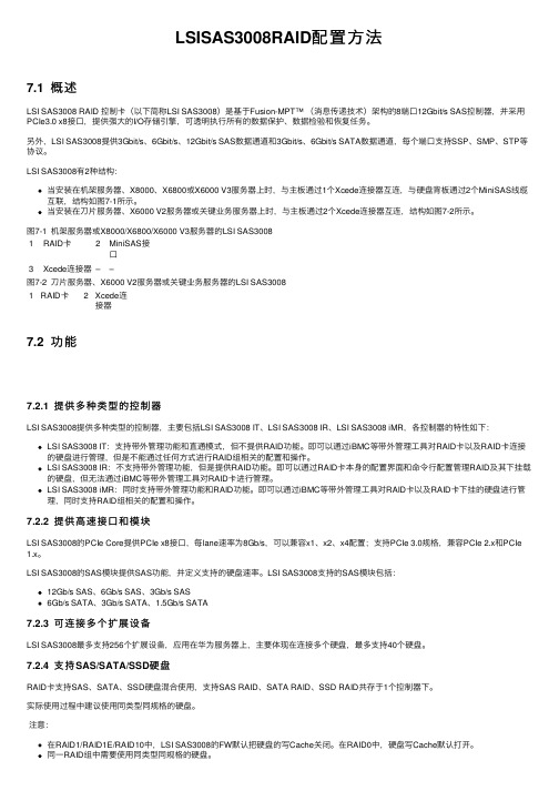
LSISAS3008RAID配置⽅法7.1 概述LSI SAS3008 RAID 控制卡(以下简称LSI SAS3008)是基于Fusion-MPT™ (消息传递技术)架构的8端⼝12Gbit/s SAS控制器,并采⽤PCIe3.0 x8接⼝,提供强⼤的I/O存储引擎,可透明执⾏所有的数据保护、数据检验和恢复任务。
另外,LSI SAS3008提供3Gbit/s、6Gbit/s、12Gbit/s SAS数据通道和3Gbit/s、6Gbit/s SATA数据通道,每个端⼝⽀持SSP、SMP、STP等协议。
LSI SAS3008有2种结构:当安装在机架服务器、X8000、X6800或X6000 V3服务器上时,与主板通过1个Xcede连接器互连,与硬盘背板通过2个MiniSAS线缆互联,结构如图7-1所⽰。
当安装在⼑⽚服务器、X6000 V2服务器或关键业务服务器上时,与主板通过2个Xcede连接器互连,结构如图7-2所⽰。
图7-1 机架服务器或X8000/X6800/X6000 V3服务器的LSI SAS30081RAID卡2MiniSAS接⼝3Xcede连接器––图7-2 ⼑⽚服务器、X6000 V2服务器或关键业务服务器的LSI SAS30081RAID卡2Xcede连接器7.2 功能7.2.1 提供多种类型的控制器LSI SAS3008提供多种类型的控制器,主要包括LSI SAS3008 IT、LSI SAS3008 IR、LSI SAS3008 iMR,各控制器的特性如下:LSI SAS3008 IT:⽀持带外管理功能和直通模式,但不提供RAID功能。
即可以通过iBMC等带外管理⼯具对RAID卡以及RAID卡连接的硬盘进⾏管理,但是不能通过任何⽅式进⾏RAID组相关的配置和操作。
LSI SAS3008 IR:不⽀持带外管理功能,但是提供RAID功能。
即可以通过RAID卡本⾝的配置界⾯和命令⾏配置管理RAID及其下挂载的硬盘,但⽆法通过iBMC等带外管理⼯具对RAID卡进⾏管理。
PCIe是什么?PCIe标准和PCIe布线规则总结概述

PCIe是什么?PCIe标准和PCIe布线规则总结概述PCI-Express(peripheral component interconnect express)是一种高速串行计算机扩展总线标准,它原来的名称为“3GIO”,是由英特尔在2001年提出的,旨在替代旧的PCI,PCI-X和AGP总线标准。
PCIe属于高速串行点对点双通道高带宽传输,所连接的设备分配独享通道带宽,不共享总线带宽,主要支持主动电源管理,错误报告,端对端的可靠性传输,热插拔以及服务质量(QOS)等功能。
PCIe交由PCI-SIG(PCI特殊兴趣组织)认证发布后才改名为“PCI-Express”,简称“PCI-E”。
它的主要优势就是数据传输速率高,目前最高的16X 2.0版本可达到10GB/s,而且还有相当大的发展潜力。
PCI Express也有多种规格,从PCI Express 1X到PCI Express 32X,能满足将来一定时间内出现的低速设备和高速设备的需求。
PCI-Express最新的接口是PCIe 3.0接口,其比特率为8GB/s,约为上一代产品带宽的两倍,并且包含发射器和接收器均衡、PLL改善以及时钟数据恢复等一系列重要的新功能,用以改善数据传输和数据保护性能。
INTEL、IBM、LSI、OCZ、三星(计划中)、SanDisk、STEC、SuperTalent和东芝(计划中)等,而针对海量的数据增长使得用户对规模更大、可扩展性更强的系统所应用,PCIe 3.0技术的加入最新的LSI MegaRAID控制器及HBA产品的出色性能,就可以实现更大的系统设计灵活性。
当然,主流主板都能能支持PCI Express 1.0 16X,也有部分较高端的主板支持PCI Express 2.016X。
PCIe标准PCI Express卡适合其物理尺寸或更大的插槽(使用×16作为最大的),但可能不适合更小的PCI Express插槽;例如,×16卡可能不适合×4或×8插槽。
PCIe3.0+USB3.0!Intel 7系芯片组解析
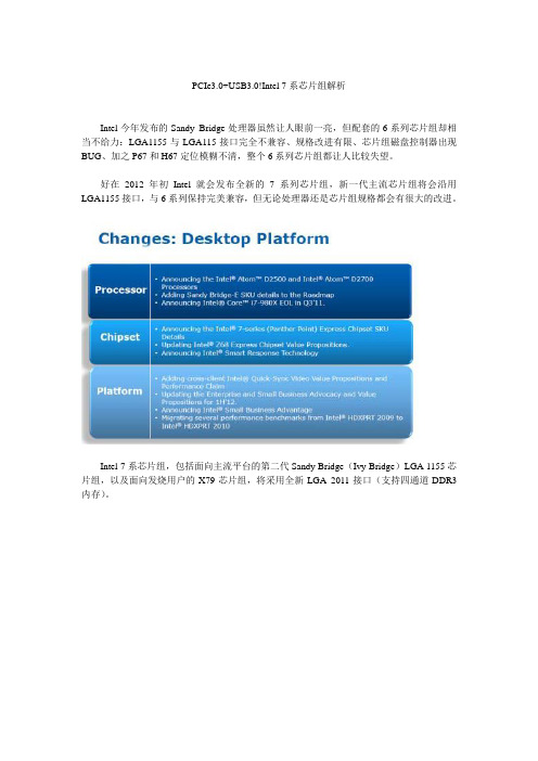
PCIe3.0+USB3.0!Intel 7系芯片组解析Intel今年发布的Sandy Bridge处理器虽然让人眼前一亮,但配套的6系列芯片组却相当不给力:LGA1155与LGA115接口完全不兼容、规格改进有限、芯片组磁盘控制器出现BUG、加之P67和H67定位模糊不清,整个6系列芯片组都让人比较失望。
好在2012年初Intel就会发布全新的7系列芯片组,新一代主流芯片组将会沿用LGA1155接口,与6系列保持完美兼容,但无论处理器还是芯片组规格都会有很大的改进。
Intel 7系芯片组,包括面向主流平台的第二代Sandy Bridge(Ivy Bridge)LGA 1155芯片组,以及面向发烧用户的X79芯片组,将采用全新LGA2011接口(支持四通道DDR3内存)。
新的工艺,新的架构以及一些新的技术值得我们期待,下面就让我们一起来分享这些即将或者将要推出的产品吧。
第2页:Z68芯片组:P67与H67的合体5月11日,Intel就将发布这款期待已久的芯片组,它采用了LGA 1155接口,支持现有的Sandy Bridge架构处理器。
Intel Z68芯片将和P67一样,拥有强大的超频能力,不过它同时也支持H67的显示输出功能,基本上我们可以把它看作是P67与H67的合体,用户就不需要再纠结于选H67还是P67的问题了,直接购买Z68即可,但价格当然要更高一些。
另外值得关注的还有Smart Response技术。
据悉Z68芯片推出时,一些主板厂商推出的主板都将捆绑Lucid V irtu软件,用户能够更具自己的需求动态切换显示模块,节能和性能两不误。
Intel Smart Response技术只在传统PC上添加一块SSD固态硬盘,让其作数据缓存只用,能够有效提高那些数据读取和写入速度,使得容量和速度得到了很好的平衡。
第3页:X79芯片组:四通道顶级平台取代X58服役了3年的X58,终于要退役,这是Intel芯片组中最长寿的芯片组之一,从推出到现在,历经岁月沧桑,一直占据高端的统治地位。
PCIe3.0+USB3.0!Intel 7系芯片组解析

PCIe3.0+USB3.0!Intel 7系芯片组解析Intel今年发布的Sandy Bridge处理器虽然让人眼前一亮,但配套的6系列芯片组却相当不给力:LGA1155与LGA115接口完全不兼容、规格改进有限、芯片组磁盘控制器出现BUG、加之P67和H67定位模糊不清,整个6系列芯片组都让人比较失望。
好在2012年初Intel就会发布全新的7系列芯片组,新一代主流芯片组将会沿用LGA1155接口,与6系列保持完美兼容,但无论处理器还是芯片组规格都会有很大的改进。
Intel 7系芯片组,包括面向主流平台的第二代Sandy Bridge(Ivy Bridge)LGA 1155芯片组,以及面向发烧用户的X79芯片组,将采用全新LGA 2011接口(支持四通道DDR3内存)。
新的工艺,新的架构以及一些新的技术值得我们期待,下面就让我们一起来分享这些即将或者将要推出的产品吧。
第2页:Z68芯片组:P67与H67的合体5月11日,Intel就将发布这款期待已久的芯片组,它采用了LGA 1155接口,支持现有的Sandy Bridge架构处理器。
Intel Z68芯片将和P67一样,拥有强大的超频能力,不过它同时也支持H67的显示输出功能,基本上我们可以把它看作是P67与H67的合体,用户就不需要再纠结于选H67还是P67的问题了,直接购买Z68即可,但价格当然要更高一些。
另外值得关注的还有Smart Response技术。
据悉Z68芯片推出时,一些主板厂商推出的主板都将捆绑Lucid Virtu软件,用户能够更具自己的需求动态切换显示模块,节能和性能两不误。
Intel Smart Response技术只在传统PC上添加一块SSD固态硬盘,让其作数据缓存只用,能够有效提高那些数据读取和写入速度,使得容量和速度得到了很好的平衡。
第3页:X79芯片组:四通道顶级平台取代X58服役了3年的X58,终于要退役,这是Intel芯片组中最长寿的芯片组之一,从推出到现在,历经岁月沧桑,一直占据高端的统治地位。
LSI公司推出LSI WarpDriveTM SLP
LSI 公司推出LSI WarpDriveTM SLP
日前,LSI 公司宣布推出LSI WarpDriveTM SLP-300 加速卡,这是一款采用PCI Express (PCIe) 标准针对应用加速的固态存储解决方案,现可搭配可选式Supermicro 服务器解决方案推出。
Supermicro 首席执行官兼总裁Charles Liang 指出:过去几年来,我们同LSI 的合作愈加密切,功能强大的突破性LSI WarpDrive 卡进一步丰富了我们广泛的服务器和存储解决方案产品系列。
WarpDrive 卡能够为我们的企业服务器客户提供简便高效的低成本应用加速功能,同时能够显着优化
数据中心的运行效率。
屡获殊荣的LSI WarpDrive SLP-300 加速卡性能高达240,000 的持续IOPS,具有小型化尺寸,支持300GB 的SLC 固态存储容量。
该解决方案旨在实现数据密集型应用和工作负载的事务处理I/O 性能最大化,满足Web 服务、数据仓库、数据挖掘、专业视频及高性能计算等应用需求。
低截面半长WarpDrive 卡能够插入Supermicro 服务器解决方案标准的8 信道PCIe Gen 2.0 插槽,以低时延和低CPU 负载实现高性能。
WarpDrive 卡无需存储支架即可提供数百个硬盘驱动器的I/O 性能,且功耗。
PCI-E NVMd
NVMe推动PCIe与闪存紧密结合当闪存时代到来,数据中心的存储会是以什么形式存在呢?磁盘时代毫无疑问,磁盘阵列是数据中心存储的主要组成部分,在磁盘阵列的组织下,大量磁盘可以并发工作,满足应用对存储性能的需求。
但是闪存不一样,闪存代表的是更简单、高效、高性能的存储。
要达到这个效果,接口和接口走的协议是非常重要的一环,SCSI/SAS的一套体系显然是无法充分发挥闪存性能的,可以预见的是PCIe/NVMe是闪存的未来。
本文也将围绕PCIe/NVMe来谈下闪存的未来。
针对磁盘可以说SAS是一个非常优良的接口,在其设计之初就将数据怎样写进磁盘进行了全面的考虑,通过HBA卡组织多块硬盘方便的组织在一起形成一个完整的存储池,另一方面SAS的接口带宽已经发展到了12Gb/s,而且当下随着光纤SAS技术的发展,其在存储阵列中的应用也越来越多,可以说SAS 是磁盘完美搭档。
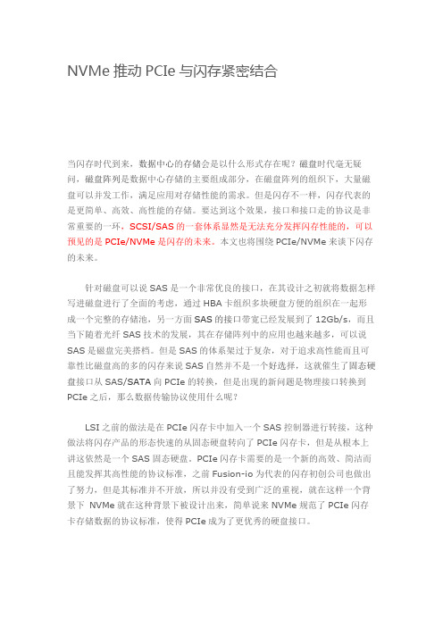
但是SAS的体系架过于复杂,对于追求高性能而且可靠性比磁盘高的多的闪存来说SAS自然并不是一个好选择,这就催生了固态硬盘接口从SAS/SATA向PCIe的转换,但是出现的新问题是物理接口转换到PCIe之后,那么数据传输协议使用什么呢?LSI之前的做法是在PCIe闪存卡中加入一个SAS控制器进行转接,这种做法将闪存产品的形态快速的从固态硬盘转向了PCIe闪存卡,但是从根本上讲这依然是一个SAS固态硬盘。
PCIe闪存卡需要的是一个新的高效、简洁而且能发挥其高性能的协议标准,之前Fusion-io为代表的闪存初创公司也做出了努力,但是其标准并不开放,所以并没有受到广泛的重视,就在这样一个背景下NVMe就在这种背景下被设计出来,简单说来NVMe规范了PCIe闪存卡存储数据的协议标准,使得PCIe成为了更优秀的硬盘接口。
从上图可以直观的看出从应用到闪存盘的过程中,到NVMe驱动器的路径要比到SAS驱动器的路径短,简化的路径缩短了数据传输的中间环节。
NVMe 相对于SCSI/SAS的延迟上的降低是非常明显的。
Intel选用LSIPCIe闪存技术——加速数据库和大数据应用

客 户 正 不 断 寻 求新 的 方 法 , 希望 能够 在加 速存 储性 能 的 同时 , 对 已有硬 盘和 直连 存储 ( D A S) 基 础 设 施 的 投 资 进 行 优化 , 这 使 得 闪 存 技 术 在 企 业 服 务 器 中得 到 快 速 普 及 。L S I N y t r o Me g a R A I D 技 术 的 独 特 之 处在 于 , 能 够 将 智 能 缓
l 1 I T AB L E AC C ES S F UL LI T ES TI 1 6 2 9 0I 1 4 1 ( 0 ) 1 0 0 : 0 0 : 0 2 l
表 大 小 MB
5. 6 32
TES T
从 以上 的 S Q L解 释 计 划 来 看 , S Q L采 用 的 是 全 表 扫 描 读 的方 式 访 问 , S Q L将 读 取 表 的 高 水 位 H WM 以 下 的
所有 数据 块 。 由 上 可 知 :( 1 ) 表 T E S T的 大 小 为 5 . 6 3 2MB,但 实 际 数 据大小 约 为 2 . 4 3 9MB, 碎 片率 约 为 5 6 . 7 %, 表 T E S T 中 存 在 大 量 的 碎 片 ;( 2 ) 查 询 该 表 所 有 记 录 所 需 要 的 时 间
加 速 数 据 库 和 大 数 据 应 用
L S I公 司 近 日 宣 布 L S I  ̄N y t r o M T Me g a R A I D@ 技 术 将 成 为 I n t e l  ̄R A I D 产 品 系 列 的 一 部 分 ,这 意 味 着 L S I与 O E M 厂 商I n t e l 公 司 的 合 作 进 一 步加 强 。
存 软件 与服 务 器端 P C I e  ̄ 闪存及 L S I领 先 的 双 核 片 上 R AI D( R O C) 技 术进 行 完 美结合 , 从 而 实现 简单 、 透 明 的应 用
PCI-E_3.0技术及发展一览剖析
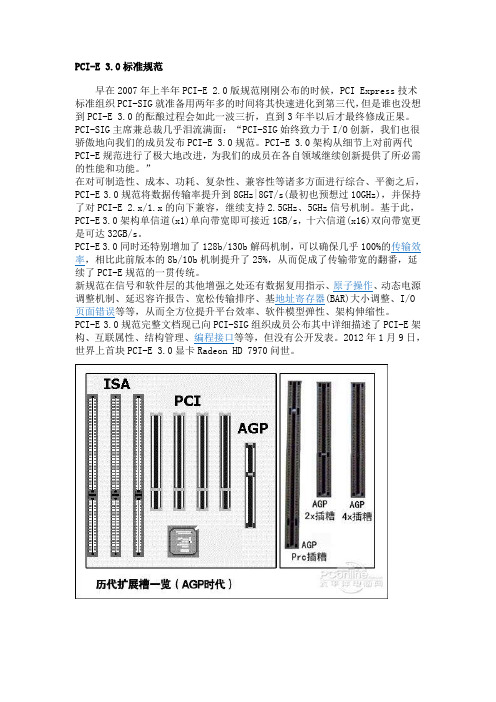
PCI-E 3.0标准规范早在2007年上半年PCI-E 2.0版规范刚刚公布的时候,PCI Express技术标准组织PCI-SIG就准备用两年多的时间将其快速进化到第三代,但是谁也没想到PCI-E 3.0的酝酿过程会如此一波三折,直到3年半以后才最终修成正果。
PCI-SIG主席兼总裁几乎泪流满面:“PCI-SIG始终致力于I/O创新,我们也很骄傲地向我们的成员发布PCI-E 3.0规范。
PCI-E 3.0架构从细节上对前两代PCI-E规范进行了极大地改进,为我们的成员在各自领域继续创新提供了所必需的性能和功能。
”在对可制造性、成本、功耗、复杂性、兼容性等诸多方面进行综合、平衡之后,PCI-E 3.0规范将数据传输率提升到8GHz|8GT/s(最初也预想过10GHz),并保持了对PCI-E 2.x/1.x的向下兼容,继续支持2.5GHz、5GHz信号机制。
基于此,PCI-E 3.0架构单信道(x1)单向带宽即可接近1GB/s,十六信道(x16)双向带宽更是可达32GB/s。
PCI-E 3.0同时还特别增加了128b/130b解码机制,可以确保几乎100%的传输效率,相比此前版本的8b/10b机制提升了25%,从而促成了传输带宽的翻番,延续了PCI-E规范的一贯传统。
新规范在信号和软件层的其他增强之处还有数据复用指示、原子操作、动态电源调整机制、延迟容许报告、宽松传输排序、基地址寄存器(BAR)大小调整、I/O 页面错误等等,从而全方位提升平台效率、软件模型弹性、架构伸缩性。
PCI-E 3.0规范完整文档现已向PCI-SIG组织成员公布其中详细描述了PCI-E架构、互联属性、结构管理、编程接口等等,但没有公开发表。
2012年1月9日,世界上首块PCI-E 3.0显卡Radeon HD 7970问世。
主板上的高速铁路,PCI-E 3.0技术及发展一览2011-7-28 18:01 | 作者:bolvar| 关键字:PCI-E3.0,5GT/s,8GT/s,PCI,PCI ExpressPCI-E作为电脑中的系统总线,不仅是显卡的数据要通过它,就连我们使用最多的USB、SATA等其他接口的数据最终都是通过PCI-E总线才与送到CPU中处理的。
9440阵列卡参数

9440阵列卡是一款高性能的存储阵列卡,具有以下参数:
* 接口类型:支持SATA、SAS和PCIe(NVMe)接口。
* 数据传输率:支持2GB 2133 MHz DDR4 SDRAM。
* 通道数:支持8个通道。
* 最多连接设备:支持SAS/SATA接口的设备最多240个,支持NVMe接口的设备最多24个。
* 插槽类型:PCI-E插槽。
* 工作电压:+12V+/-8%,3.3V+/-9%。
* 工作温度:0-55℃。
* 物理尺寸:6.127英寸x 2.712英寸。
* 主机总线类型:x8 lane PCI Express 3.1。
* 缓存保护:CacheVault CVPM05。
* 管理软件:LSI存储机构(LSA)、StorCLI(命令行接口)、HII(UEFI人机接口基础设施)。
* 内部连接器:2 Mini-SAS HD x4 SFF-8643。
以上参数仅供参考,具体参数可能会因产品版本或生产批次不同而有所差异,建议查阅产品说明书或与厂商联系获取准确信息。
三三不息——PCI—E3.0即将走来

空间 ,降低 了总 线压 力 ,也对提 升 了更 宽广 的
带宽的支持 。
P - . 案 已不 凡 CI E 3 0草
目前P — .还是 以草案形 式 CI 3 E 0 存 在的 ,即便如此 ,还 是可 看到 作 为 下一代 的主 流接 口带 来 的出色 设
外 ,设备和 设备 之 间也能 利用这 种
包括A MD HD5 7 以及NV DI 90 I A未来 和更 为 困难 的布线 设计 。可 以预 计 的是 ,P — .肯定会提升 接 口供 CI 30 E 将推 出的F r 以及挑 战光线追踪 的 emi 电能 力 ,但是否达  ̄3 o o w之 高的水 计算模 式 ,因此 高接 口带宽 是必 须 的。在P IE 3 接 口上 ,带宽再 次 平 ,还有待商榷。 C — . 0 翻倍 ,达到了单通道单 向1 /的极 GB s 速传输 ,使P I C— E×1插槽能够提供 6
接 口带宽。
板供 电带来 困扰 。P - 口的 电 P — . QP 总线或者 HT CIE接 CI 3  ̄ E O I 总线可 能供给来 自于主板2 P n 口, 目前 以 直 接 互 联 互 通 ,降 低 了 存 取 延 4 i接
的7 W最 大 电能 尚可 应付 ,一 旦提 迟 ,并能够让C U不经过 北桥或者相 5 P
协 议传 输数 据并 直接 通信 ,不需 要
北 桥 中转 ,也 不需 要再纳 入CP U的 绝对控 制之 下 。这种 设计 进一步 减 轻 了CP U的处理 压 力 ,并 令本来 就 颇 显堵塞 的QP 、HT总线等释放 了 I
3 GB s 2 /的最大双 向数据 带宽 。很 显
然 ,无论 是复 杂 的纹 理 还是通 用计
C— E C — 3 允许P I E 0 C— E 已经达到了双 向8 B s G /的带宽 。紧接 接 口的显卡都将直接从P I 插槽 取 输的复杂程度 ,P I . 得足 够 的供 电 ,不 再需 要外 接 电源 总线 与其 他不 同传输 协议 的设 备总 着 ,P IE 2 又将此 数据翻倍 ,让 C — . 0 PI C— E×1插槽显卡获得了1GB s 6 6 /的 的辅 助 。不过 提升 功耗很 可 能给主 线 进 行 动 态 转 换 。利 用 此 协 议 ,
LSI Nytro MegaRAID应用加速卡介绍
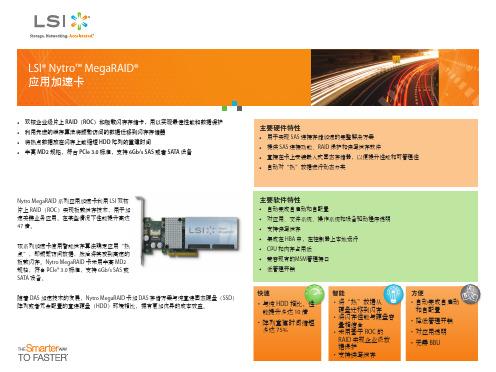
主要硬件特性
用于实现 SAS 连接存储加速的完整解决方案 提供 SAS 连接功能、RAID 保护和读写缓存软件 直接在卡上安装嵌入式固态存储器,以便提升性能和可管理性 自动对“热”数据进行动态分类
Nytro MegaRAID 系列应用加速卡利用 LSI 双核 片上 RAID(ROC)实现板载缓存技术,用于加 速关键业务应用。在某些情况下性能提升高达 47 倍。 该系列加速卡使用智能缓存算法确定应用“热 点”,即频繁访问数据,然后将其放到高速的 板载闪存。Nytro MegaRAID 卡采用半高 MD2 规格,符合 PCIe® 3.0 标准,支持 6Gb/s SAS 或 SATA 设备。 随着 DAS 加速技术的发展,Nytro MegaRAID 卡加 DAS 存储方案与纯直连固态硬盘(SSD) 阵列或者冗余配置的直连硬盘(HDD)环境相比,拥有更加优异的成本效益。
LSI Nytro MegaRAID 卡订购信息 存储器类型 SLC eMLC eMLC 容量 100GB 200GB 800GB 部件编号 LSI00350 LSI00351 LSI00353 LSI00355 Nytro MegaRAID 8100-4i Nytro MegaRAID 8110-4i Nytro MegaRAID 8120-4i
用于 DRAM 缓存保护的 Nytro MegaRAID SCM-01 SuperCap 套件
物理尺寸 内部连接器 设备支持 主机总线类型 数据传输率 用于 RAID 缓存辅助的 DDR 存储器 RAID 数据保护特性
工作温度 工作电压和功耗 合规认证
如需了解更多信息和销售办事处所在地,敬请访问以下 LSI 网站: /channel
主要软件特性
自动完成自启动和自配置 对应用、文件系统、操作系统和设备驱动程序透明 支持读写缓存 集成在 HBA 中,在控制器上本地运行 CPU 和内存占用低 兼容现有的MSM管理接口 低管理开销
PCIe_3GSAS_UG[1]
![PCIe_3GSAS_UG[1]](https://img.taocdn.com/s3/m/2f8eef8ecc22bcd126ff0c60.png)
USER’SGUIDEPCI Express to 3.0-Gb/sSerial Attached SCSI(SAS) Host Bus AdaptersModel Numbers:SAS3041E,SAS3041ELSAS3042E,SAS3042ELSAS3080E,SAS3080ELSAS3081E,SAS3081ELSAS3442E,SAS3442ELSAS3444E,SAS3444ELSAS3800ESAS3801E,SAS3801ELSAS31601EJ u n e2007Version 2.0iiElectromagnetic Compatibility NoticesThis device complies with Part 15of the FCC Rules.Operation is subject to the following two conditions:1.This device may not cause harmful interference,and 2.This device must accept any interference received,including interference that may cause undesired operation.This equipment has been tested and found to comply with the limits for a Class B digital device,pursuant to part 15of the FCC Rules.These limits are designed to provide reasonable protection against harmful interference in a residential installation.This equipment generates,uses,and can radiate radio frequency energy and,if not installed and used in accordance with the instructions,may cause harmful interference to radio communications.However,there is no guarantee that interference will not occur in a particular installation.If this equipment does cause harmful interference to radio or television reception,which can be determined by turning the equipment off and on,the user is encouraged to try to correct the interference by one or more of the following measures:•Reorient or relocate the receiving antenna.•Increase the separation between the equipment and the receiver.•Connect the equipment into an outlet on a circuit different from that to which the receiver is connected.•Consult the dealer or an experienced radio/TV technician for help.Shielded cables for SCSI connection external to the cabinet are used in the compliance testing of this Product.LSI is not responsible for any radio or television interference caused by unauthorized modification of this equipment or the substitution or attachment of connecting cables and equipment other than those specified by LSI.The correction of interferences caused by such unauthorized modification,substitution,or attachment will be the responsibility of the user.The LSI PCI Express to 3.0-Gb/s SAS host bus adapters (SAS3041E,SAS3041EL,SAS3042E,SAS3042EL,SAS3080E,SAS3080EL,SAS3081E,SAS3081EL,SAS3442E,SAS3442EL,SAS3444E,SAS3444EL,SAS3800E,SAS3801E,SAS3801EL and SAS31601E)are tested to comply with FCC standards for home or office use.This Class B digital apparatus meets all requirements of the Canadian Interference-Causing Equipment Regulations.Cet appareil numérique de la classe B respecte toutes les exigences du Règlement sur le matériel brouilleur du Canada.This is a Class B product based on the standard of the Voluntary Control Council for Interference from Information Technology Equipment (VCCI).If this is used near a radio or television receiver in a domestic environment,it may cause radio interference.Install and use the equipment according to the instructionmanual.LSI Asia,Inc.Taiwan Branch 10/F ,156,Min Sheng E.Rd.,Section 3,Taipei,Taiwan,R.O.C.Tel:886.2.2718.7828FAX:886.2.2718.8869LSI Corporation North American Headquarters Milpitas,CA Tel:408.433.8000Proprietary Rights NoticeThis document contains proprietary information of LSI Corporation.Theinformation contained herein is not to be used by or disclosed to third partieswithout the express written permission of an officer of LSI Corporation. Document DescriptionDocument DB15-000363-01,June2007This document describes revision/release_2.0of LSI Corporation’s SAS3041E,SAS3041EL,SAS3042E,SAS3042EL,SAS3080E,SAS3080EL,SAS3081E,SAS3081EL,SAS3442E,SAS3442EL,SAS3444E,SAS3444EL,SAS3800E,SAS3801E,SAS3801EL and SAS31601E PCI Express to3.0-Gb/s SAS host busadapters user’s guide and will remain the official reference source for allrevisions/releases of this product until rescinded by an update.DisclaimerIt is the policy of LSI Corporation to improve products as new technology,components,software,andfirmware become available.LSI reserves the right tomake changes to any products herein at any time without notice.All features,functions,and operations described herein may not be marketed by LSI in allparts of the world.In some instances,photographs andfigures are of equipmentprototypes.Therefore,before using this document,consult your LSIrepresentative for information that is applicable and current.LSI CORPORA TIONDOES NOT ASSUME ANY RESPONSIBILITY OR LIABILITY FOR THE USE OFANY PRODUCTS DESCRIBED HEREIN EXCEPT AS EXPRESSL Y AGREEDTO IN WRITING BY LSI CORPORA TION.LSI products are not intended for use in life-support appliances,devices,ore of any LSI product in such applications without written consent ofthe appropriate LSI officer is prohibited.License RestrictionThe purchase or use of an LSI Corporation product does not convey a licenseunder any patent,copyright,trademark,or other intellectual property right of LSIor third parties.iiiCopyright NoticeCopyright©2006,2007by LSI Corporation.All rights reserved. Trademark AcknowledgmentsLSI,the LSI logo design and Fusion-MPT are trademarks or registeredtrademarks of LSI Corporation.All other brand and product names may betrademarks of their respective companies.SAFor a current list of our distributors,sales offices,and design resourcecenters,view our web page located ativPrefaceThis document is the user’s guide for the LSI PCI Express to3.0-Gb/sSAS host bus adapters,referred to as LSI PCIe to SAS host busadapters.It contains a functional description of the LSI PCIe to SAS hostbus adapters as well as physical and electrical specifications.It alsocontains instructions for installing the host bus adapters and forconnecting SAS devices.AudienceThis document assumes that you have some familiarity with SerialAttached SCSI(SAS)devices and PCI Express devices.This documentbenefits people installing and using the LSI PCIe to SAS host busadapter.OrganizationThis document has the following chapters:•Chapter1,Introduction,describes the LSI PCIe to SAS host busadapters.•Chapter2,Hardware Installation,describes how to install the LSIPCIe to SAS host bus adapters in a system.•Chapter3,Host Bus Adapter Characteristics,provides theenvironmental and electrical specifications for the LSI PCIe to SAShost bus adapters.This chapter also provides the mechanicaldrawings and connector locations for the LSI PCIe to SAS host busadapters.PCIe to3.0-Gb/s SAS Host Bus Adapters User’s Guide vRelated PublicationsLSI DocumentsLSISAS1064E PCI Express to4-Port Serial Attached SCSI ControllerTechnical Manual,Document No.DB14-000331-02LSISAS1068E PCI Express to8-Port Serial Attached SCSI ControllerTechnical Manual,Document No.DB14-000330-02Fusion-MPT™Device Management User’s Guide,Document No.DB15-000186-01Integrated RAID User’s Guide,Document No.DB15-000292-00Integrated RAID for SAS User’s Guide,Document No.DB15-000357-00ANSIInterNational Committee on Information Technology Standards(INCITIS)T10Technical CommitteeGlobal Engineering DocumentsPCI Special Interest Groupvi PrefaceRevision RecordVersion Date Remarks2.06/2007This release provides information about the SAS3042E,SAS3042EL andSAS31601E PCI Express to3.0-Gbs SAS host bus adapters.1.08/2006This release provides information about the SAS3041E,SAS3041EL,SAS3080E,SAS3080EL,SAS3081E,SAS3081EL,SAS3442E,SAS3442EL,SAS3443E,SAS3443EL,SAS3444E,SAS3444EL,SAS3800E,SAS3801E,andSAS3801EL PCI Express to3.0-Gb/s SAS host bus adapters.Several of thesehost bus adapters were previously featured in the3-Gb/s Serial Attached SCSIHost Bus Adapters User’s Guide(March2006,Version2.0).Preface viiviii PrefaceContentsChapter1Introduction1.1Overview1-11.2Features1-31.3PCI Performance1-41.4Software1-6 Chapter2Hardware Installation2.1Quick Installation Instructions2-12.2More Detailed Installation Instructions2-2 Chapter3Host Bus Adapter Characteristics3.1Characteristics of the LSI PCIe to SAS HBAs3-13.1.1SAS3041E and SAS3041EL HBAs Characteristics3-23.1.2SAS3042E and SAS3042EL HBAs Characteristics3-43.1.3SAS3080E and SAS3080EL HBAs Characteristics3-63.1.4SAS3081E and SAS3081EL HBAs Characteristics3-83.1.5SAS3442E and SAS3442EL HBAs Characteristics3-103.1.6SAS3444E and SAS3444EL HBAs Characteristics3-123.1.7SAS3800E HBA Characteristics3-143.1.8SAS3801E and SAS3801EL HBAs Characteristics3-163.1.9SAS31601E HBA Characteristics3-183.2Electrical and Environmental Specifications3-203.2.1Electrical Characteristics3-203.2.2Thermal and Atmospheric Characteristics3-213.2.3Safety Characteristics3-21Contents ixCustomer Feedback x ContentsFigures2.1Installing an LSI PCIe to SAS x8HBA in a PCI Express Slot2-33.1SAS3041E and SAS3041EL Board Layout3-33.2SAS3042E and SAS3042EL Board Layout3-53.3SAS3080E and SAS3080EL Board Layout3-73.4SAS3081E and SAS3081EL Board Layout3-93.5SAS3442E and SAS3442EL Board Layout3-113.6SAS3444E and SAS3444EL Board Layout3-133.7SAS3800E Board Layout3-153.8SAS3801E and SAS3801EL Board Layout3-173.9SAS31601E Board Layout3-19Contents xiCopyright©2006-2007by LSI Corporation.All rights reserved.xii ContentsCopyright©2006-2007by LSI Corporation.All rights reserved.Tables1.1LSI PCIe to SAS HBAs and Controllers1-21.2SAS Bandwidths1-31.3Software Support1-63.1Maximum Power Requirements3-20Contents xiiiCopyright©2006-2007by LSI Corporation.All rights reserved.xiv ContentsCopyright©2006-2007by LSI Corporation.All rights reserved.Chapter1IntroductionThis chapter describes the LSI PCI Express to3.0-Gb/s SAS host busadapters and consists of the following sections:•Section1.1,“Overview”•Section1.2,“Features”•Section1.3,“PCI Performance”•Section1.4,“Software”1.1OverviewThe LSI PCIe to SAS host bus adapters(HBAs)provide four or eightserial ports for connection to SAS/SATA(Serial ATA)devices.Each portis capable of a SAS link rate and a SAT A link rate of3.0-Gb/s.The PCIExpress transmission and reception data rate is2.5-Gb/s in eachdirection,yielding a total bandwidth of5.0-Gb/s for each full-duplex lane.The LSI PCIe to SAS HBAs are implemented using four or eight PCIExpress PHYs,which provide possible host-side maximum transmissionand reception rates of up to4.0-GB/s.The LSI PCIe to SAS HBAs contain Flash ROM for storing the BIOS andfirmware,and NVSRAM for storing nonvolatile RAID information.TheSAS3442E,SAS3442EL,SAS3444E,SAS3444EL,SAS3800E,SAS3801E,SAS3801EL and SAS31601E HBAs provide a128K x36-bPBSRAM memory device for storing SAS Address Port informationallowing for connection to more than128devices.The LEDs on theHBAs report a heartbeat,activity,and fault conditions when detected byfirmware.Fusion-MPT™firmware operates the HBA.The PCI Express interface is compliant with the PCI ExpressSpecification,revision1.0a.All PCI software is backwards compliant withPCIe to3.0-Gb/s SAS Host Bus Adapters User’s Guide1-1Copyright©2006-2007by LSI Corporation.All rights reserved.previous versions of the PCI/PCI-X specifications.The LSI PCIe to SASproducts implement the PCI Express interface as a x4or x8interface.The LSI PCIe to SAS HBAs use either a standard PCI or a low-profilePCI bracket type.The LSI PCIe to SAS Host bus adapter(HBA)SASinterface is compatible with the ANSI Serial Attached SCSI Specification,revision1.0and the Serial AT A Specification,revision1.0a.The functionality of LSI PCIe to SAS HBAs come from either theLSISAS1064E controller chip or the LSISAS1068E controller chip.TheLSISAS1064E integrates four high-performance SAS/SATA PHYs andthe LSISAS1068E integrates eight high-performance SAS/SATA PHYs.The design of LSI PCIe to SAS HBAs makes it easy to add SASinterfaces to any computer,workstation,or server with a PCI Expressbus.Table1.1shows the LSI PCIe to SAS controllers and their associatedHBAs that support SAS/SATA devices.All board numbers contain an“E”after the numeric portion of their name,indicating that they use the PCIExpress bus.Boards without an“L”after the numbers in their name usea standard PCI bracket type.Boards with an“L”after the numbers intheir name use a low-profile PCI bracket type.Table1.1LSI PCIe to SAS HBAs and ControllersControllers LSI PCIe to SAS HBAsLSISAS1064E SAS3041E,SAS3041EL,SAS3042E,SAS3042ELLSISAS1068E SAS3080E,SAS3080EL,SAS3081E,SAS3081EL,SAS3442E,SAS3442EL,SAS3444E,SAS3444EL,SAS3800E,SAS3801E,SAS3801EL,SAS31601E1-2IntroductionCopyright©2006-2007by LSI Corporation.All rights reserved.1.2FeaturesThis section lists features of the LSI PCIe to SAS HBAs:•Supports narrow port and wide port as shown in Table1.2.Table1.2SAS BandwidthsHalf Duplex Full DuplexNarrow Port(1Lane)300-MB/s Narrow Port(1Lane)600-MB/sWide Port(2Lanes)600-MB/s Wide Port(2Lanes)1200-MB/sWide Port(4Lanes)1200-MB/s Wide Port(4Lanes)2400-MB/s•Supports SSP,STP,and SMP as defined in the Serial Attached SCSI(SAS)Specification,version1.0.•Supports SAT A as defined in the Serial ATA Specification,version1.0a.•Provides configurable drive spin-up sequencing on a per-PHY basis.•Simplifies cabling with a point-to-point,serial architecture.•Provides smaller and thinner cables that do not restrict airflow.•Provides a serial,point-to-point,enterprise-level storage interface.•Transfers data using SCSI information units.•Provides two LEDs for each PHY to indicate link activity and faultsfor the SAS3041E,SAS3041EL,SAS3042E,SAS3042EL,SAS3080E,SAS3080EL,SAS3081E,SAS3081EL,SAS3442E,SAS3442EL,SAS3444E,SAS3444EL,SAS3800E,SAS3801E,SAS3801EL and SAS31601E host board adapters(HBAs).•Provides two light pipes routed through the PCI bracket for theSAS3041E,SAS3041EL,SAS3042E,SAS3042EL,SAS3080E,SAS3080EL,SAS3081E,SAS3081EL,SAS3442E,SAS3442EL,SAS3444E,SAS3444EL,and SAS3800E HBAs.One light pipeindicates activity on any PHY.The other light pipe indicates aheartbeat or a fault condition.The SAS3801E and SAS3801EL usetwo LEDs routed through the PCI bracket for the same purpose.•Provides compatibility with SAT A target devices.Features1-3Copyright©2006-2007by LSI Corporation.All rights reserved.1.3PCI PerformanceLSI PCIe to SAS HBA boards support the PCI Express interface.ThePCI Express features of the LSI PCIe to SAS HBAs include:•Provides four(boards using LSISAS1064E)or eight(boards usingLSISAS1068E)PCI Express PHYs•Supports a single-PHY(1lane)link transfer rate up to2.5-Gb/s ineach direction•Supports x8,x4,and x1link widths•Automatically downshifts to a x4link width if plugged into a x4connector or into a x8connector that is wired as a x4connector •Provides a scalable interface–Single-lane aggregate bandwidth of up to0.5-GB/s(500-MB/s)–Quad-lane aggregate bandwidth of up to2.0-GB/s(2000-MB/s)–8-lane aggregate bandwidth of up to4.0-GB/s(4000-MB/s)•Supports serial,point-to-point interconnections between devices–Reduces the electrical load of the connection–Enables higher transmission and reception frequencies•Supports lane reversal and polarity inversion•Supports PCI express hot plug•Supports power management–Supports PCI power management1.2–Supports Active State Power Management(ASPM),including theL0,L0s,L1states,by placing links in a power-savings modeduring times of no link activity•Contains a replay buffer that preserves a copy of the data forretransmission in case a CRC error occurs•Supports the PCI Express advanced error reporting capabilities•Uses a packetized and layered architecture1-4IntroductionCopyright©2006-2007by LSI Corporation.All rights reserved.•Achieves a high bandwidth per pin with low overhead and low latency•PCI Express is software compatible with PCI and PCI-X software –Leverages existing PCI device drivers–Supports the memory,I/O,and configuration address spaces –Supports memory read/write transactions,I/O read/write transactions,and configuration read/write transactions •Provides4-KB of PCI configuration address space per device •Supports posted and non-posted transactions•Provides quality of service(QOS)link configuration and arbitration policies•Supports traffic class0and class one virtual channel •Supports message signaled interrupts(both MSI and MSI-X)as well as INTx interrupt signaling for legacy PCI support•Supports end-to-end CRC(ECRC)and advanced error reporting PCI Performance1-5 Copyright©2006-2007by LSI Corporation.All rights reserved.LSI Confidential1.4SoftwareThe LSI PCIe to SAS HBAs support all major operating systems,asshown in T able1.3.Table1.3Software SupportOS Support VersionsWindows XP,2000,Server200332-b and64-b(x86,AMD,and IA-64)Linux:Red Hat Enterprise Linux(RHEL)3and4Linux:SuSE Enterprise Server(SLES)8and9Novel NetWare 5.1and6.5Sun Sparc Solaris 2.6,2.7,2.8,2.9,and2.10Utilities Install,Flash and BIOS Configuration UtilityThe LSI PCIe to SAS HBAs use the Fusion-MPT architecture for allmajor operating systems,which allows for thinner drivers for betterperformance.T o obtain a device driver that supports your operatingsystem,contact an LSI Technical Support representative at719-533-7230or visit our web site at .1-6IntroductionCopyright©2006-2007by LSI Corporation.All rights reserved.Chapter2Hardware InstallationThis chapter provides both quick instructions and detailed instructions onhow to install the LSI PCIe to3.0-Gb/s SAS HBA.This chapter consistsof the following sections:•Section2.1,“Quick Installation Instructions”•Section2.2,“More Detailed Installation Instructions”2.1Quick Installation InstructionsThe following steps summarize the installation instructions.Use these instructions to install your LSI PCIe to SAS HBA if you arecomfortable with the installation procedure.Section2.2,“More DetailedInstallation Instructions”provides detailed installation instructions.1.Unpack the HBA and inspect it for damage.2.Turn off the system and remove the power cords.3.Remove the cover from the system.4.Insert the HBA in an available PCI Express slot.5.Secure the bracket to the system’s chassis.6.Connect the serial cables between the HBA and the serial hard diskdrives.Figure2.1illustrates the locations of the connectors on yourHBA.7.Replace the cover and the power cords,and then power-up thesystem.LSI PCIe to SAS HBA hardware installation is complete.PCIe to3.0-Gb/s SAS Host Bus Adapters User’s Guide2-1Copyright©2006-2007by LSI Corporation.All rights reserved.2.2More Detailed Installation InstructionsThe following steps provide detailed installation instructions:1.Unpack the HBA in a static-free environment.Contact LSI or yourOEM support representative if the HBA appears to be damaged.2.Turn off the system power and physically disconnect the power cord.3.Remove the cover from the system and disconnect the system fromany networks.4.Insert the HBA in an available PCI Express slot.Press down gentlybutfirmly to properly seat the HBA in the slot.Figure2.1illustrateshow to insert the HBA in a PCI Express slot.5.Install the bracket screw,when present,or engage the system’sretention mechanism to secure the HBA to the system’s chassis.6.Connect the serial cables between the HBA and the serial hard diskdrives(HDD).Figure2.1illustrates the locations of the connectors onyour HBA.7.Replace the system’s cover,reconnect the power cords,and thenpower-up the system.LSI PCIe to SAS HBA hardware installation is complete.2-2Hardware InstallationCopyright©2006-2007by LSI Corporation.All rights reserved.More Detailed Installation Instructions2-3Copyright ©2006-2007by LSI Corporation.All rights reserved.Figure 2.1Installing an LSI PCIe to SAS x8HBA in aPCI Express SlotNote:The HBA shape,size,and locations of components on yourx8(or x4)HBA and its bracket may vary from thisillustration.A PCI Express connector is smaller than aPCI/PCI-X connector.32-b Slots64-b Slots(3.3V)(3.3V)Edge ofHost Board Bracket Press HerePress HereHDDConnectorSerial Signal Cables HBA to HDD4 Lane Internal HBA Connector 4 LaneExternalPCBReceptacleand CablewithJackscrewsScrew SFF-8484SFF-8470Breakout CablePCI Express x8 Slot2-4Hardware InstallationCopyright©2006-2007by LSI Corporation.All rights reserved.Chapter3Host Bus AdapterCharacteristicsThis chapter describes the characteristics of the LSI PCIe to3.0-Gb/sSAS HBAs.The chapter includes these topics:•Section3.1,“Characteristics of the LSI PCIe to SAS HBAs”•Section3.2,“Electrical and Environmental Specifications”3.1Characteristics of the LSI PCIe to SAS HBAsThe LSI PCIe to SAS HBAs use either the LSISAS1064E controller orthe LSISAS1068E controller.The LSISAS1064E controller connects upto four SAS/SAT A devices to a computer system through the PCIExpress interface.The LSISAS1068E controller connects up to eightSAS/SAT A devices to a computer system through the PCI Expressinterface.The LSI controllers are implemented using either four(LSISAS1064E)or eight(LSISAS1068E)PCI Express PHYs.Each PHYoperates at2.5-Gb/s,which provides possible host-side maximumtransmission and reception rates of up to4.0-GB/s.The LSISAS1064E controller chip and the LSISAS1068E controller chipcontain the PCI Express functionality for the LSI PCIe to SAS HBAs.Thecontroller chip connects directly to the PCI Express bus and generatestiming and protocol in compliance with the PCI Express specification.The LSISAS1064E controller chip and the LSISAS1068E controller chipcontain the SAS/SAT A functionality for the LSI PCIe to SAS HBAs.Thecontroller chips connect channels directly to the SAS/SATA devices.The LSI PCIe to SAS HBAs provide a2M x8-b Flash ROM for storingthe BIOS andfirmware.The LSI PCIe to SAS HBAs provide up to32Kx8-b NVSRAM for storing the nonvolatile RAID information when asystem failure happens.The SAS3442E,SAS3442EL,SAS3444E,PCIe to3.0-Gb/s SAS Host Bus Adapters User’s Guide3-1Copyright©2006-2007by LSI Corporation.All rights reserved.SAS3444EL,SAS3800E,SAS3801E,SAS3801EL and SAS31601EHBAs provide a128K x36-b PBSRAM memory device for storing SASAddress Port information allowing for connection to more than128devices.3.1.1SAS3041E and SAS3041EL HBAs CharacteristicsThe SAS3041E and SAS3041EL are the same HBA with the exceptionof the PCI bracket.The SAS3041E uses a standard PCI bracket and theSAS3041EL uses the low-profile(LPPCI)PCI bracket.Figure3.1showsthe HBAs and their brackets.3.1.1.1LEDsThe SAS3041E and SAS3041EL HBAs have four LEDs,labeled A0–A3,that turn green to indicate an activity condition on any of the four PHYs.There are four LEDs,labeled LNP0–LNP3,that turn yellow to indicate afault condition on any of the four PHYs.See Figure3.1for LED locations.The SAS3041E and SAS3041EL HBAs have two light pipes routedthrough the PCI bracket.One light pipe turns green to indicate activityon any PHY.The other light pipe is bi-color.Itflashes green to indicatethe LSISAS1064E heartbeat,or it turns yellow when the LSISAS1064Efirmware detects a fault condition.3.1.1.2ConnectorsThis section describes the connectors on the SAS3041E andSAS3041EL HBAs.See Figure3.1for connector locations.PCI Express Connector(J1)–The PCI Express interface has four PCIExpress lanes,which provide possible host-side maximum transmissionand reception rates of up to2.0-GB/s.The PCI Express connection ismade through the edge connector J1.The signal definitions and pinnumbers conform to the PCI Express specifications.SAS/SATA Connectors(J2,J5–J7)–The SAS3041E supportsSAS/SATA connections through connectors J2(Port3),J5(Port2),J6(Port1),and J7(Port0).These connectors are SA TA internal right-angleconnectors.3-2Host Bus Adapter CharacteristicsCopyright©2006-2007by LSI Corporation.All rights reserved.Characteristics of the LSI PCIe to SAS HBAs3-3Copyright ©2006-2007by LSI Corporation.All rights reserved.Activity LED Header (J3)–The connector is a 4-pin,right angle,0.1-inch pitch,pin header for driving external activity LEDs.Figure 3.1SAS3041E and SAS3041EL Board Layout•J1:PCI Express x4lane board edge connector •J2,J5–J7:SAT A internal right-angle connectors •J3:4-pin,right angle,0.1-inch pitch,pin header for driving external activity LEDs 3.1.1.3Physical CharacteristicsThe SAS3041E and SAS3041EL boards are 6.6inches x 2.713inches.PCI Express x4connection is made through the edge connector J1.The component height on the top and the bottom of the SAS3041E and SAS3041EL boards follows the PCI Express specifications.J1J3J5J6J7J2J4Standard PCI Bracket(LPPCI)Low-ProfilePCI Bracket SAS3041ESAS3041ELT wo Light Pipes,One Green andOne Bi-color LSISAS1064E Activity LEDsLink Not Present LEDsPort 0Port 1Port 3Port 23.1.2SAS3042E and SAS3042EL HBAs CharacteristicsThe SAS3042E and SAS3042EL are identical HBAs with the exceptionof the PCI bracket.The SAS3042E uses a standard PCI bracket and theSAS3042EL uses a low-profile(LPPCI)PCI bracket.Figure3.2showsthe HBAs and their brackets.3.1.2.1LEDsThe SAS3042E and SAS3042EL HBAs have four LEDs,labeled A0–A3,that turn green to indicate an activity condition on any of the four PHYs.There are four LEDs,labeled LNP0–LNP3,that turn yellow to indicate afault condition on any of the four PHYs.See Figure3.2for LED locations.The SAS3042E and SAS3042EL HBAs have two light pipes routedthrough the PCI bracket.One light pipe turns green to indicate activityon any PHY.The other light pipe is bi-color.Itflashes green to indicatethe LSISAS1064E heartbeat,or it turns yellow when the LSISAS1064Efirmware detects a fault condition.3.1.2.2ConnectorsThis section describes the connectors on the SAS3042E andSAS3042EL HBAs.See Figure3.2for connector locations.PCI Express Connector(J1)–The PCI Express interface has eightPCI Express lanes,which provide possible host-side maximumtransmission and reception rates of up to4.0-GB/s.The SAS3042E orSAS3042EL supports x8,x4,and x1PCI Express link widths,andautomatically downshifts if plugged into either a x4connector or into ax8connector that is wired as a x4connector.The connection is madethrough the edge connector J1.The signal definitions and pin numbersconform to the PCI Express specifications.SAS/SATA Connector(J5)–The SAS3042E and SAS3042EL supportsSAS connections through connector J5.The J5connector is an SFF-8484SAS internal right-angle connector with four sideband lines.Activity LED Header(J6)–The connector is a4-pin,right angle,0.1-inch pitch,pin header for driving external activity LEDs.3-4Host Bus Adapter CharacteristicsCopyright©2006-2007by LSI Corporation.All rights reserved.。
LSI发布PCI Express 固态存储解决方案样片

LSI发布PCI Express 固态存储解决方案样片
佚名
【期刊名称】《电子与电脑》
【年(卷),期】2010(000)004
【摘要】@@ LSI公司日前宣布面向OEM客户提供PCI Express?(PCIe)固态存储(SSS)解决方案样片.LSISSS6200 PCIeSSS卡为企业级服务器提供了一款具有更高可靠性、业界领先存储密度的高性能存储解决方案.为了简化系统集成与管理,SSS卡采用了业界标准SAS协议和广泛部署的LSl SAS软件.
【总页数】1页(P64)
【正文语种】中文
【相关文献】
1.LSI发布业界首款面向新一代PCI Express3.0服务器平台的6 Gbit/s SASRoC芯片 [J],
2.NI公司发布PCI和PCI Express总线的高性价比6 1/2位数字万用表业界首款PCI Express DMM问世 [J],
3.LSI推出PCI Express固态存储卡支持渠道产品系列 [J],
4.LSI发布面向新一代PCI Express 3.0服务器平台的6Gb/s SAS RoC芯片 [J],
5.LSI和Intel将MegaRAID解决方案扩展到PCI Express [J],
因版权原因,仅展示原文概要,查看原文内容请购买。
PCIe接口Replay Buffer含义探讨

PCIe接口Replay Buffer含义探讨
陈乃塘
【期刊名称】《《电子测试》》
【年(卷),期】2006(000)002
【摘要】PCle 的出现成就了PCI 总线的世代交替,并取代了AGP 8x 绘图卡接口。
从英特尔9xx 系列芯片组的进化已看出其企图。
虽然 PCle x16取代 AGP 8x 的任务在台式机和笔记本电脑上都能圆满达成,但在外围的应用上则尚未开花结果。
市
面上能够看到的一些千兆以太网络卡或是 PCle-SATA II 转接卡都是些过渡性产物,本文主要针对 PCle 接口 Replay Buffer 如何实现数据完整性传送进行剖析。
【总页数】5页(P49-53)
【作者】陈乃塘
【作者单位】资深电子技术专栏
【正文语种】中文
【中图分类】TN7
【相关文献】
1.基于Protocol Buffers的配置下发接口适配与应用 [J], 寇阳;吕建新
2.PCIe接口Replay Buffer含义探讨 [J], 陈乃塘
3.接口技术再探索 PCIe接口卡热插拔机制解析 [J], 陈乃塘
4.接口技术再探索PCIe接口卡热插拔机制解析 [J], 陈乃塘
5.LSI推出业界首款PCIe3.0接口的PCIe闪存卡 [J],
因版权原因,仅展示原文概要,查看原文内容请购买。
三三不息PCI-E3.0即将走来

三三不息PCI-E3.0即将走来
佚名
【期刊名称】《电脑迷》
【年(卷),期】2010(000)005
【摘要】"3"在2009年和2010年,都是非常特殊的幸运数字。
2009年,我们看到了SATA3.0、USB3.0的诞生,而2010年,大家将有机会见证PCI-E3.0的诞生。
相比之下,作为视觉设备和其他扩展设备主要接口的PCI-E3.0,意义比前两者更显重要。
【总页数】1页(P41)
【正文语种】中文
【相关文献】
1.赛灵思推出符合PCI-E3.0标准的集成模块 [J],
2.PCI-E3.0标准三年热身赛现在终于来了 [J],
3.关于N卡的PCI-E3.0补丁 [J], KKK
4.点燃极速之旅 NVMe PCI-E3.0 SSD独家首测 [J],
5.2011,即将到来的这一年——移动和无线向企业IT走来 [J],
因版权原因,仅展示原文概要,查看原文内容请购买。
LSI TrueStore存储IC技术助力单盘容量达1TB的硬盘驱动器

LSI TrueStore存储IC技术助力单盘容量达1TB的硬盘驱动
器
佚名
【期刊名称】《《电子与电脑》》
【年(卷),期】2011(000)010
【摘要】LSI公司日前宣布其TrueStore硬盘驱动器(HDD)存储IC已经集成到业界近期推出的3.5英寸硬盘驱动器中,该硬盘驱动器的每张盘片容量可达1TB,创造了单张磁盘的最新容量记录。
【总页数】1页(P82-82)
【正文语种】中文
【中图分类】TP333.35
【相关文献】
1.LSI新一代前置放大器IC为硬盘驱动器提供了业界一流的性能 [J],
2.LSI针对移动硬盘驱动器推出新一代前置放大器IC [J],
3.Spansion助力互联网数据中心服务器降低能耗达75%并扩展存储容量新型Spansion(R) EcoRAMTM存储协助解决日益突出的数据中心能耗危机 [J], Spansion公司
4.LSI与Seagate联袂开发新一代大容量硬盘驱动器技术 [J],
5.Cornice微硬盘驱动器采用杰尔系统TRUESTORE~CE芯片组实现便携式设备高容量存储 [J],
因版权原因,仅展示原文概要,查看原文内容请购买。
- 1、下载文档前请自行甄别文档内容的完整性,平台不提供额外的编辑、内容补充、找答案等附加服务。
- 2、"仅部分预览"的文档,不可在线预览部分如存在完整性等问题,可反馈申请退款(可完整预览的文档不适用该条件!)。
- 3、如文档侵犯您的权益,请联系客服反馈,我们会尽快为您处理(人工客服工作时间:9:00-18:30)。
剩下的干净空气可以直接排人空气中。 排气管发生堵塞。该系统不需要任何稀 释空气 , 因
借助使用端清除技术 , S A L I X能够有效 防止其 光 。I c的工作电压范围为 4 . 5 至3 6 伏, 可以承受汽 车系统 中出现的高达 4 0伏的甩负荷 。 I 2 C接 口允许用户单独设置 L E D电流 , 每L E D 通道高达 6 0 m A 。 相邻 的通道可以组合在一起 , 以驱
导体制造提供最高分辨率及影像质量 , 先进的系统
设计 与全 自主式功能 ,能提 高 1 0 0 %更快 速 的产
出。
包括台积电 、英特尔等半导体大厂 ,已经展开 Wa r p D r i v e 加速卡 ,同时整个 N y t r o M e g a R A I D产品 1 0 n m的研发作业 , 应用材料在其 S E M V i s i o n系列设 系列的容量、 连接功能和软件功能均有新发展 。 新产
新型使 用端 有害气体 清除系统
位于德 国德累斯顿的 D A S E n v i r o n m e n t a l E x p e r t
公 司是 半 导 体行 业 废 气处 理 企 业 , 该 企业 研 发 出名
鳍式场效 晶体管 ( F i n F E T ) 及 l O n m制程高深宽 比
( AD C) 系统 高智 能 的机器 学 习算法 , 同时为 半导体
业界最小级别 2 9 2 4 尺寸。由于改善 了散热特性, 体 积虽小却可实现高输出功率 。按照与以往产品同等
亮 度进 行设 计 时 , 还可 实现更 低耗 电量 。( 来 自罗姆
半 导体 )
产业引进首创缺陷检测扫瞄电子显微镜 ( D R S E M)
巾 国 集 成 电 路
C hi na I nt egr at ed Ci r cui t
业界要 闻
—
计 ,并且 利用 罗姆 独 家 的模 具技 术 采用 了非球 面透 镜, 从 而 实 现 了非球 面 透镜 的 面贴 装 L E D产 品 中的
备上 , 推出一套最新缺陷检测及分类技术, 该设备的 缺陷分析系统结合前所未有高分辨率 、多维影像分 析功能 ,及革 命性创新 的 P u r i t y自动化缺 陷分类
技术。
S E MV i s i o n G 6系统 设 备 的分 辨率 , 相 较 于 前一
D A S 研 发 出面 向湿 式 蚀 刻 清 洗工 艺 的
款提高了 3 0 %, 为业界最高 。这项能力与其独特的 电子光束倾角 ,使其优异并且经过实地应用验证的 缺陷检测扫描电子显微镜能够辨别 、 分析及发现 3 D
Al l e g r o Mi c r o S y s t e ms 公 司宣布 推 出适 用 于 L C D
学和物理吸附的两阶段洗涤流程 ,在其源头从气流
中直 接清 除有 害 物质 。借 助分离 式 出风 口,有 害气
体从湿式蚀刻清洗 台的加工腔室进入预洗涤器 , 后 者通过使用喷嘴对气体进行预清洁 。从这里开始 , 废气进入首个洗涤阶段 , 随后才是第二阶段 , 并采用
个L E D通道单独控制 , 如需要可以独立启用 / 禁用 各个通道 。( 来 自A l l e g r o 公司 )
L S I 推 出业 界 首 款
P C I e 3 . 0接 口的 P C I e闪存 卡
L S I 公司 日 前宣布 , 其L S I P C I e闪存适配器 L S I N y t r o 产品组合又添新成员 ,即 3 . 2 T B高容量 N y t何 技 术或环 境威 胁 ,
背光 、仪表板和 白天行驶灯的全 新可编程多输 出
L E D驱 动器 。 A l l e g r o的 A 8 5 1 7整 合 了带 内置 电源 开 关 的 电流型 升 压稳压 器 和 1 0个 I C可编程 电流吸 收 器 ,在 2 0 0 H z时 可提 供 5 , 0 0 0 : 1的对 比率 P WM 调
结构 的缺陷 。 ( 来 自应用 材 料 )
为S A L I X的新型系统。 S A L I X是一种有害气体清除
系统 , 主要针 对 湿式蚀 刻 清洗 台应用 。 S A L I X利用 化
A l l e g r o 公 司推 出 全新 1 O 通道 L E D 汽 车驱 动 器
h t t p: # www. c i c ma g . c o n r
L 一 业 界 要闻
品使业界最为全面的 P C I e 闪存适配器产 品得到进
一
巾 国 集 成 电 路
Chi na I nt egr at ed Ci r cui t
和电学变量优化。该流程既解决 了随机和系统 良率 问题 ,又为客户的 2 8 n m设计提供另一种成熟 的制 程整合了业 界领先的 D F M预防 、 分析和签收能力 , 包括 C a d e n c e 光刻物理分析器 ( L P A) 、 C a d e n c e 模 板分析 、 C a d e n c e 光刻 电学分析器 ( L E A) 和C a d e n c e 化学机械抛光预测 ( C C P) 技术 。 对于 2 8 n m和以后产品 ,关键在于精准预测 和 自动修复 D F M“ 热点” 加速产 出时间。联华 电子人
动更 高 电 流的 L E D 串 。P WM 调光 占空 比可 针对 每
此精心制备的干净空气会依然 留在净室之中 ,以进
一
步 降低成本。 ( 来自D A S 公司 )
应 用材料 新检测设 备支持 1 O n m
应用材料宣布推出新世代的缺陷检测及分类技
术 ,加速达成 l O n m及 以下的顶尖芯片生产 良率 。 S E M V i s i o n G 6系统独特 的多维影像 分析功能为半
