eetop[1].cn_[----]A multi-stage CMOS charge pump for low-voltage memories
multisim中英文对照表

菜单部分菜单中英文对照表一、File〈文件>New-——--———--———------——-—〈新建〉Reset————-----——-——---—-—-〈重置〉Open——----——-—-—-————----—〈打开〉Save——--——-——--———---———--—〈保存〉Save As-—-—----——-—-——---—〈保存为〉Save selected---——-—-—-<保存选择〉XRef Objects ---——----—-〈外部引用物体〉XRef Scenes —--———-————〈外部引用场景〉Merge ---—-—---———-———————<合并〉Merge Animation-—-———-—〈合并动画动作〉Replace———-—-—-------—---〈替换>Import—------—-—---—-———-——<输入>Export-—---—--—--——-——---—-<输出〉Export Selected—————————-〈选择输出〉Archive-———--—---——-——-—-—-<存档〉Summary Info—--——----——<摘要信息〉File Properties--——-—---—〈文件属性〉View Image File---————-〈显示图像文件>History----—-------—--———--〈历史>Exit--————--—---——-——----—〈退出〉二、Edit<菜单〉Undo or Redo-——-----—-〈取消/重做〉Hold and fetch-————-——-〈保留/引用〉Delete—----———-—-—----〈删除〉Clone-————---—--———---—-—〈克隆〉Select All-————-—-—-—--————〈全部选择〉Select None—--——--——-——-〈空出选择>Select Invert-——--———--——-<反向选择〉Select By-——-—-—---——-—--—<参考选择〉Color-———--—--—--—---——-—〈颜色选择> Name——---—-——————--—-—--—〈名字选择〉Rectangular Region—-———〈矩形选择>Circular Region——----—-〈圆形选择〉Fabce Region-——————-—-〈连点选择〉Lasso Region—--———---—<套索选择〉Region:-—------—-——-—--——-〈区域选择〉Window-——-———--—-—-——--〈包含〉Crossing—-——--—-——-———---〈相交〉Named Selection Sets<命名选择集〉Object Properties—————-——〈物体属性〉三、Tools〈工具〉Transform Type—In-——--—〈键盘输入变换〉Display Floater——-————----〈视窗显示浮动对话框〉Selection Floater------——〈选择器浮动对话框〉Light Lister--—————--—-——-—-〈灯光列表〉Mirror-——-—---—-—--———-——-———<镜像物体〉Array-—----—-———-—-—---------〈阵列>Align--——-—--—————---—-—-—-—〈对齐〉Snapshot—---———-——————————〈快照〉Spacing Tool———-—————----〈间距分布工具〉Normal Align---—--———-—-—<法线对齐〉Align Camera————---—-——-〈相机对齐>Align to View—-—--—-—--————<视窗对齐〉Place Highlight---————-———〈放置高光〉Isolate Selection-——-—--——<隔离选择〉Rename Objects—---————--〈物体更名〉四、Group〈群组〉Group——--—--———-—--——--—---—<群组>Ungroup-———--—------—-————<撤消群组〉Open——————-—-———---—-——---—〈开放组〉Close———-—-—--——-———-—-—-——-〈关闭组> Attach-----————-—-—-——-—--——-<配属〉Detach————-——--—-———--——-——〈分离〉Explode——--——-———-————-—---〈分散组>五、Views<查看〉Undo View Change/Redo View change〈取消/重做视窗变化> Save Active View/Restore Active View〈保存/还原当前视窗>Viewport Configuration—-—-———---—---〈视窗配置〉Grids---—-—-————-—————-———--——-—————-——<栅格〉Show Home Grid----—-——----——-—--〈显示栅格命令〉Activate Home Grid—-—--—--—----——〈活跃原始栅格命令>Activate Grid Object—-—--—---——————<活跃栅格物体命令> Activate Grid to View--—--———————--〈栅格及视窗对齐命令〉Viewport Background-——-----————〈视窗背景〉Update Background Image-————〈更新背景>Reset Background Transform〈重置背景变换〉Show Transform Gizmo-————----〈显示变换坐标系>Show Ghosting——-—----—-——--——---—<显示重橡〉Show Key Times—-—————-—---——-———<显示时间键〉Shade Selected—--—--—--—-——-—-—-—〈选择亮显〉Show Dependencies—-—-----—--—<显示关联物体〉Match Camera to View—-—--—-———〈相机与视窗匹配〉Add Default Lights To Scene—<增加场景缺省灯光>Redraw All Views-----—-———-—-—-—〈重画所有视窗〉Activate All Maps--——-—-——-——-——-—-〈显示所有贴图〉Deactivate All Maps--——---—-—-———〈关闭显示所有贴图〉Update During Spinner Drag —-〈微调时实时显示〉Adaptive Degradation Toggle-—-〈绑定适应消隐〉Expert Mode——-————----———-———--——〈专家模式〉六、Create<创建〉Standard Primitives-—-----———-——-〈标准图元〉Box—--—--——--——--—-—--—--—-————-—---——-〈立方体〉Cone-——---———-—--———-—---——-——————-—-〈圆锥体〉Sphere--—---------——---———-----——--—-〈球体〉GeoSphere--—--——-———--——--————-———〈三角面片球体〉Cylinder——-—-------—---------—---—---<圆柱体〉Tube—-——-—----——--—-—----—-——-—---——-〈管状体〉Torus-—-—---——————--—-—-—-------—-—--〈圆环体〉Pyramid——-—-—------——-——--—————--——-〈角锥体〉Plane——-—-—-—-------——--—---——--—--——〈平面>Teapot--——----—--———-—-—--———--—-—--—〈茶壶>Extended Primitives—--—---—--——-〈扩展图元〉Hedra--------—-—————-—----—--------—-〈多面体〉Torus Knot——----————--—--—---—----—〈环面纽结体>Chamfer Box---—--——--—-—————-—-——<斜切立方体〉Chamfer Cylinder---—-————--——---〈斜切圆柱体〉Oil Tank—-—-——-----—-—--—-—--—————--〈桶状体〉Capsule----————--—-——-—--——-—--—-—-〈角囊体〉Spindle—--—-—---————————-———--—-—---〈纺锤体〉L—Extrusion----———-——-—-—--——-—----〈L形体按钮〉Gengon—————-—-——----——-——---———————<导角棱柱〉C-Extrusion-—---—-—-----—-—--—-———<C形体按钮>RingWave---————-——--——-——--—————-〈环状波〉Hose--——-—--—-—--——-—-——-———-—--————〈软管体> Prism——-—————-—-—---—-—--——-—-——-———<三棱柱〉Shapes-——--——--—--—-—--—-——-—-——-—〈形状> Line—-——----————-——-—-————-—————-————〈线条〉Text-——--—------—-——--—--—-———----—-—-〈文字〉Arc———--—-————-—-———-———-——----—--—-—-<弧> Circle—-———---—--——---————-—————---—-〈圆>Donut-———--——--—--————-———---—---—--〈圆环〉Ellipse——--—-—-—--——-—--——----————---<椭圆〉Helix-——-——-—-—-—-—--——-----—-—-—--—-〈螺旋线〉NGon-————---———--—---—--———--————-—〈多边形〉Rectangle—--—-——---——-—--——-———-——〈矩形〉Section——---—-——--—--—-—----------——〈截面〉Star-——-——---—-———-————-——--——--————-〈星型〉Lights———---————-----—---———---————-〈灯光〉Target Spotlight—————--—----—----〈目标聚光灯>Free Spotlight-————--—--—---—-—-—-〈自由聚光灯>Target Directional Light-----—-<目标平行光〉Directional Light——-—-——---————-—〈平行光〉Omni Light—---—---—---——-—-—-———-<泛光灯〉Skylight—------——----—-—--——-——-——-—〈天光〉Target Point Light--——---———----〈目标指向点光源〉Free Point Light—--——-———--—----〈自由点光源>Target Area Light————-————-----〈指向面光源〉IES Sky—--—----—-———————--—-—————-〈IES天光〉IES Sun-—---——-—————--—-—-—-——---<IES阳光〉SuNLIGHT System and Daylight〈太阳光及日光系统〉Camera-—————--—---—----—--——--——<相机〉Free Camera———---—————-———--——〈自由相机〉Target Camera———----—-—----—-〈目标相机〉Particles-——-—----———----———---——-〈粒子系统> Blizzard—————--------—-———-—-—-——-〈暴风雪系统〉PArray----——---——--—--———------—--〈粒子阵列系统〉PCloud-—-—-——---——-———-——-—-—---—〈粒子云系统〉Snow-—---—--—----——---—---—-———---〈雪花系统>Spray—--————---—--—-—-—-—————-—-—-〈喷溅系统〉Super Spray——-—-————-——-———---—〈超级喷射系统〉词汇中英文对照Absolute Mode Transform Type—in绝对坐标方式变换输入Absolute/Relative Snap Toggle Mode绝对/相对捕捉开关模式ACIS Options ACIS选项Activate活动;激活Activate All Maps激活所有贴图Activate Grid激活栅格;激活网格Activate Grid Object激活网格对象;激活网格物体Activate Home Grid激活主栅格;激活主网格ActiveShade实时渲染视图;着色;自动着色ActiveShade(Scanline)着色(扫描线)ActiveShade Floater自动着色面板;交互渲染浮动窗口ActiveShade Viewport自动着色视图Adaptive适配;自动适配;自适应Adaptive Cubic立方适配Adaptive Degradation自动降级Adaptive Degradation Toggle降级显示开关Adaptive Linear线性适配Adaptive Path自适应路径Adaptive Path Steps适配路径步幅;路径步幅自动适配Adaptive Perspective Grid Toggle适配透视网格开关Add as Proxy加为替身Add Cross Section增加交叉选择Adopt the File’s Unit Scale采用文件单位尺度Advanced Surface Approx高级表面近似;高级表面精度控制Advanced Surface Approximation高级表面近似;高级表面精度控制Adv. Lighting高级照明Affect Diffuse Toggle影响漫反射开关Affect Neighbors影响相邻Affect Region影响区域Affect Region Modifier影响区域编辑器;影响区域修改器Affect Specular Toggle影响镜面反射开关AI Export输出Adobe Illustrator(*.AI)文件AI Import输入Adobe Illustrator(*.AI)文件Align对齐Align Camera对齐摄像机Align Grid to View对齐网格到视图Align Normals对齐法线Align Orientation对齐方向Align Position对齐位置(相对当前坐标系)Align Selection对齐选择Align to Cursor对齐到指针Allow Dual Plane Support允许双面支持All Class ID全部类别All Commands所有命令All Edge Midpoints全部边界中点;所有边界中心All Face Centers全部三角面中心;所有面中心All Faces所有面All Keys全部关键帧All Tangents全部切线All Transform Keys全部变换关键帧Along Edges沿边缘Along Vertex Normals沿顶点法线Along Visible Edges沿可见的边Alphabetical按字母顺序Always总是Ambient阴影色;环境反射光Ambient Only只是环境光;阴影区Ambient Only Toggle只是环境光标记American Elm美国榆树Amount数量Amplitude振幅;幅度Analyze World分析世界Anchor锚Angle角度;角度值Angle Snap Toggle角度捕捉开关Animate动画Animated动画Animated Camera/Light Settings摄像机/灯光动画设置Animated Mesh动画网格Animated Object动画物体Animated Objects运动物体;动画物体;动画对象Animated Tracks动画轨迹Animated Tracks Only仅动画轨迹Animation动画Animation Mode Toggle动画模式开关Animation Offset动画偏移Animation Offset Keying动画偏移关键帧Animation Tools动画工具Appearance Preferences外观选项Apply Atmospherics指定大气Apply—Ease Curve指定减缓曲线Apply Inverse Kinematics指定反向运动Apply Mapping指定贴图坐标Apply—Multiplier Curve指定增强曲线Apply To指定到;应用到如需转载,请注明来自FanE『翻译中国』http;//www。
eetop[1].cn_基于0_6_mCMOS工艺1_56GHz环形压控振荡器设计
![eetop[1].cn_基于0_6_mCMOS工艺1_56GHz环形压控振荡器设计](https://img.taocdn.com/s3/m/28b8868ca0116c175f0e4866.png)
[ 2 ] 袁晟 ,冯军 ,王骏峰 ,王志功. 10Gb / s 0. 18μm CMOS时钟恢 复芯片 [ J ]. 电子器件 , 2003, (12).
仪表技术
所设计的环形压控振荡器进行了仿真 。结果如图 3。
— 45 —
图 3 压控振荡器的起振时间
图 3中的 a, b两图分别是使用容性源极耦合差分 放大器和普通差分放大器电路的起振时间图 ,可以看 出使用容性源极耦合差分放大器电路的起振时间很 短 ,起振较快 。
图 4是压控振荡器的仿真电压输出波形图 ,可以 看出输出波形具有完美的周期性 。
3 结论 采用 0. 6μm CMOS工艺设计了容性源极耦合差分
放大器为延时单元的环形压控振荡器 。模拟结果表 明 ,在 + 5V 电源电压作用下 ,该压控振荡器的调谐范 围为 600MHz, 自 由 振 荡 的 频 率 为 1. 56GHz, 功 耗 为 16. 2mW ,该振荡器能很好的用在锁相环中 。 参考文献 :
4 结语
本文通过上述方法对 OPM 系统的模拟实现 ,避 免了对该系统采用光电探测器阵列进行实现的繁琐
步骤 ,从而达到节省成本的目的 。目前主要是在台 式机上实现该系统的功能 ,下一步的试验重点将是 把该功能移植到 DSP 上实现 ,从而达到批量生产的 目的 。
参考文献 :
[ 1 ] 侯国屏 ,王 | ,叶齐鑫. LabV IEW 7. 1 编程与虚拟仪器设计 [M ]. 北京 :清华大学出版社 , 2005.
应用 [ J ]. 电子工程师 , 2000, (4). (许雪军编发 )
cmos模拟集成电路设计流程

cmos模拟集成电路设计流程CMOS模拟集成电路设计流程CMOS模拟集成电路(Complementary Metal-Oxide-Semiconductor Analog Integrated Circuit)是一种常见的电路设计技术,它在现代电子领域中具有重要的应用价值。
CMOS模拟集成电路设计流程是指设计师根据特定的需求和要求,通过一系列的步骤来完成电路设计的过程。
下面将介绍CMOS模拟集成电路设计的主要流程。
第一步是需求分析。
在这一步骤中,设计师需要与客户或系统需求方进行沟通,了解电路的功能、性能和特殊要求。
设计师需要明确电路的输入输出关系、电源要求、精度要求等,以便后续的设计过程能够满足这些需求。
第二步是电路拓扑设计。
在这一步骤中,设计师需要选择合适的电路拓扑结构。
根据需求分析的结果,设计师可以选择不同的电路结构,如放大器、滤波器、振荡器等。
设计师需要考虑电路的稳定性、带宽、功耗等因素,并进行合理的权衡和选择。
第三步是电路参数设计。
在这一步骤中,设计师需要确定电路的具体参数,如电流源大小、电阻值、电容值等。
设计师可以通过手工计算、仿真软件等方法来确定这些参数,以满足电路的性能要求。
同时,设计师还需要考虑电路的可靠性和稳定性,避免出现不稳定的工作状态或性能退化的问题。
第四步是电路布局设计。
在这一步骤中,设计师需要将电路的各个元件进行布局,确定它们的相对位置和连接方式。
设计师需要考虑电路元件之间的电磁干扰、电源耦合等问题,并进行合理的布局设计,以提高电路的性能和可靠性。
同时,还需要考虑电路的面积、功耗等因素,以满足集成电路的制造要求。
第五步是电路模拟和验证。
在这一步骤中,设计师需要使用专业的电路仿真软件对设计的电路进行模拟和验证。
通过输入合适的输入信号,设计师可以观察电路的输出响应,并进行相应的参数调整和优化,以满足电路的性能要求。
同时,设计师还需要考虑温度、工作范围等因素对电路性能的影响,以保证电路的可靠性和稳定性。
CMOS设置图解教程(详细)

完全CMOS设置图解教程(1)CMOS设置直接关系到电脑的性能,甚至影响到您的设备能否正常使用。
或许您已经会使用一些简单CMOS设置,比如设置启动驱动器,改变倍频等等,但这些是远远不够的,想要让你的电脑发挥出最优性能,首先我们就要彻底的了解CMOS设置的基础知识。
那么下面这篇CMOS设置图解教程就可以让您轻松的掌握这些知识。
一.进入CMOS Setup设置在打开计算机电源后的几秒钟的时间内,电脑首先进行POST(Power On Self Test,开机自检),在这个时候按下“Del”键后,就可以看到下图所示的CMOS Setup主菜单。
在主菜单中你可以选择不同的设置选项,按上下左右方向键来选择,按“Enter”键进入子菜单。
1.功能键说明(向上键)移到上一个选项(向下键)移到下一个选项(向左键)移到左边的选项(向右键)移到右边的选项Enter键选择当前项目Esc键回到主画面,或从主画面中结束Setup程序Page Up或+键改变设置状态,或增加栏位中的数值内容Page Down或-键改变设置状态,或减少栏位中的数值内容F1功能键显示目前设置项目的相关说明F5功能键装载上一次设置的值F6功能键装载最安全的值F7功能键装载最优化的值F10功能键储存设置值并离开CMOS Setup程序2.子菜单说明请注意设置菜单中各项内容.如果菜单项左边有一个三角形的指示符号,表示若选择了该项子菜单,将会有一个子菜单弹出来.3.辅助说明当你在Setup主画面时,随着选项的移动,下面显示相应选项的主要设置内容。
当你在设置各个栏位的内容时,只要按下“F1”,便可得到该栏位的设置预设值及所有可以的设置值,如BIOS缺省值或CMOS Setup缺省值。
如果想离开辅助说明窗口,只须按“Esc”键即可。
二.Standard CMOS Features(标准CMOS功能设置)在Standard CMOS Features中,主要是为了设置IDE硬盘的种类,以顺利开机,除此之外,还要设置日期、时间、软驱规格及显示卡的种类。
eetop[1].cn_Astro使用操作流程
![eetop[1].cn_Astro使用操作流程](https://img.taocdn.com/s3/m/df121c669b6648d7c1c746c1.png)
Astro使用操作流程首先设置软件工作需要的环境,指令为:>source .cshrc将当前工作环境切换到根目录下,避免软件Astro与StarRC冲突。
图1接下来启动Astro软件,输入指令:Astro 。
打开该软件的界面(图1)。
然后首先要做好载入设计对象前的准备工作,所以先点击TOOLS选项下面的data prep选项使软件做好载入数据之前的准备。
图2然后选择netlist in 下的verilog in to cel 选项选择需要载入的对象库。
得到如下图3的选项卡,分别选择library name 、verilog file name、tech file name 以及对应高低电平1和0的电源和地的选项net name for 1’b1和net name for 1’b0。
其中verilog file name是后缀为.v的文件,tech file的文件后缀是tf(图4)。
图3 选择完以上路径后点击global net option给整个设计的VDD和GND定义,如图5所示。
然后选择选项reference lib 选择设计需要的参考工艺库CZ6H.3AL.tf(图6)。
这个库是除了工艺tech file以外仍然需要的库CZ6H_3AL_IO和CZ6H_ptf_5V_LIB,该库的后缀也为tf,位置位于找F/LIB/ps/_astro下面。
图4 图5图6完成以上操作后就可以选择设计所需要的设计库和单元了,在这里点击选择library和CELL选项下面的open就可以得到如图7 所示的简单版图布局了。
图7接下来可以对布局需要的版图位置进行设置了,在这里选择选项design setup下的set up floorplan进行版图位置的设置了,如图8所示。
Row core ratio选项一般选择1,决定了金属布线通道在芯片中占的布线通道的大小,当为1时表明金属布线通道不占用芯片周围的空间而是在芯片内部电路结构的上方走线。
模拟cmos集成电路设计英文版
模拟cmos集成电路设计英文版IntroductionA complementary metal-oxide-semiconductor (CMOS) integrated circuit (IC) is a type of electronic circuit that uses CMOS technology to integrate digital or analog circuits on a single chip. In this article, we will discuss the design process for a CMOS IC.Design flowThe design flow for a CMOS IC involves several stages, which are as follows:1. Requirements gathering: This stage involves gathering information about the requirements of the IC, such as its functionality, performance, and power requirements.2. Design specification: Based on the requirements gathered in the previous stage, a design specification is created that outlines the functional blocks of the IC, their interfaces, and their performance specifications.3. Circuit design: This stage involves designing the individual circuits that make up the IC, such as logic gates, amplifiers, and oscillators.4. Layout design: Once the circuits have been designed, the layout design stage involves placing the circuits on the chip and wiring them together.5. Simulation and verification: Simulation is used to verify the performanceof the circuits and the entire IC before it is fabricated.6. Tape-out: This is the process of preparing the design files for fabrication.Fabrication processThe fabrication process of a CMOS IC involves several steps, which are as follows:1. Substrate preparation: The starting material for the IC is a silicon wafer, which is coated with a layer of oxide.2. Gate oxidation: A thin layer of oxide is grown on the wafer surface where the gates of the transistors will be located.3. Poly-Si deposition: A layer of polycrystalline silicon (poly-Si) is deposited on the gate oxide layer.4. Photolithography: A series of masks are used to define the pattern of the transistors, interconnects, and other features on the chip.5. Etching: Chemical etching is used to remove the unwanted material from the wafer surface.6. Implantation: Ions are implanted into the wafer to create the source, drain, and gate regions of the transistors.7. Metal deposition: A layer of metal is deposited on top of the transistorsand interconnects for electrical contacts.8. Planarization: Chemical-mechanical polishing is used to planarize the surface of the chip.9. Packaging: The IC is packaged in a protective casing and tested for functionality and performance.ConclusionThe design and fabrication of a CMOS IC involves a complex process that requires expertise in multiple areas, such as digital and analog circuit design, layout design, and fabrication technology. However, the resulting IC can be a powerful tool for a wide range of applications, from consumer electronics to industrial control systems.。
cmos checksum error

CMOS Checksum Error1. IntroductionThe CMOS (Complementary Metal-Oxide-Semiconductor) checksum error is an error message that appears when the computer’s CMOS settings have been corrupted or modified incorrectly. This error can occur during the startup process, typically when the computer is powered on or restarted. The CMOS is a small amount of memory on the computer’s motherboard that stores important system information, including the computer’s date and time settings, hardware configuration, and BIOS settings.In this document, we will discuss the causes of the CMOS checksum error, the potential consequences, and the possible solutions to resolve this error.2. Causes of CMOS Checksum Errora. Weak or Dead CMOS BatteryOne of the most common causes of the CMOS checksum error is a weak or dead CMOS battery. The CMOS battery provides power to the CMOS memory even when the computer is turned off. If the battery is weak or dead, it can cause the CMOS settings to be lost or corrupted, resulting in the checksum error. In this case, replacing the CMOS battery is the recommended solution.b. Incorrect BIOS SettingsModifying the BIOS settings incorrectly can also lead to the CMOS checksum error. When the computer starts up, the BIOS performs a checksum test to ensure that the CMOS settings are correct. If the checksum does not match the expected value, the error message is displayed. This can happen if the user manually changes the BIOS settings without a proper understanding or accidentally modifies the wrong settings.c. Power Surges or Electrical InterferencesPower surges or electrical interferences can cause the CMOS to become corrupted and result in the checksum error. These fluctuations in power supply can disrupt the proper functioning of the CMOS memory and lead to incorrect checksum values. To prevent such issues, it is important to use a surge protector or uninterruptible power supply (UPS) to stabilize the power supply to the computer.d. Faulty HardwareIn some cases, the CMOS checksum error can be caused by faulty hardware, such as a failing RAM module or a damaged motherboard. These hardware issues can disrupt the communication between the CMOS and the BIOS, resulting in a checksum error. In such situations, troubleshooting the hardware components and replacing any faulty parts may be necessary.3. Consequences of CMOS Checksum ErrorThe CMOS checksum error can have several consequences on the computer’s functioning. Some of the potential consequences include:•Incorrect date and time: The computer may not display the correct date and time, which can lead to issues with scheduling, synchronization, and file management.•Booting issues: The computer may encounter difficulties in booting up properly. It may fail to start orcontinuously restart due to the checksum error.•Unstable system: The corrupted CMOS settings can result in an unstable system, causing unexpected crashes, freezing, or sudden shutdowns.•Inconsistent hardware configuration: The checksum error can cause the computer to forget or misidentify the installed hardware components, leading to compatibility issues and decreased performance.4. Resolving CMOS Checksum ErrorTo resolve the CMOS checksum error, several possible solutions can be tried:a. Replace CMOS BatteryIf a weak or dead CMOS battery is the cause of the error, replacing the battery is necessary. The CMOS battery is usuallya small coin-shaped battery located on the motherboard. It is relatively easy to replace by removing the old battery and inserting a new one of the same type.b. Reset BIOS SettingsResetting the BIOS settings to their default values can help resolve the checksum error. This can be done by accessing the BIOS setup utility during the computer startup process. Look for an option to reset or load default settings and confirm the changes. Keep in mind that resetting the BIOS may also reset any customized settings, so make a note of any important changes before proceeding.c. Update BIOS FirmwareIn some cases, updating the computer’s BIOS firmware can address the CMOS checksum error. Manufacturers often release BIOS updates that fix known issues and improve system stability. It is important to check the computer or motherboard manufacturer’s website for the latest BIOS update and follow the instructions provided to perform the update.d. Check Hardware ConnectionsEnsure that all hardware components are properly connected to the computer. Loose or faulty connections can cause communication errors and lead to a checksum error. Check the connections of RAM modules, hard drives, and other peripherals and reseat them if necessary.e. Seek Professional AssistanceIf the above solutions do not resolve the CMOS checksum error, it is recommended to seek professional assistance. A computer technician or the manufacturer’s supp ort team can provide further guidance and troubleshooting steps specific to the computer’s hardware and firmware configuration.5. ConclusionThe CMOS checksum error is an error message that indicates incorrect or corrupted CMOS settings. It can have various causes, including a weak CMOS battery, incorrect BIOS settings, power surges, or faulty hardware. The consequences of this error can disrupt the computer’s performance and lead to booting issues, instability, and incorrect system configuration. Resolving the checksum error involves replacing the CMOS battery, resetting BIOS settings, updating BIOS firmware, checking hardware connections, or seeking professional assistance. By addressing the underlying cause, users can restore the proper functioning of their computers and prevent further issues related to the CMOS checksum error.。
单片lna cmos工艺 节点 eetop

单片lna cmos工艺节点eetop什么是单片LNA CMOS工艺?单片LNA CMOS工艺是一种集成在单个芯片上的低噪声放大器(LNA)技术,利用CMOS工艺将放大器电路与其他电子器件集成在一起。
CMOS 是互补金属氧化物半导体的缩写,是一种常见的半导体制造工艺,用于制造集成电路。
为什么要使用单片LNA CMOS工艺?单片LNA CMOS工艺提供了许多优势,使其在无线通信和射频应用中得到广泛采用。
首先,CMOS工艺是一种成本效益高、易于批量生产的制造技术。
与其他工艺相比,CMOS工艺具有更低的制造成本和更高的生产率,这使得单片LNA CMOS工艺成为一种经济有效的选择。
此外,CMOS工艺还具有较低的功耗和较小的面积要求。
由于CMOS工艺使用的是可控硅材料,其功耗较低,使单片LNA CMOS工艺非常适合移动设备和便携式无线通信应用。
此外,CMOS工艺还可以实现小尺寸的芯片设计,这对于微型化无线设备和系统来说是至关重要的。
单片LNA CMOS工艺的关键步骤是什么?单片LNA CMOS工艺包括一系列的关键步骤,从物理设计到电路测试。
以下是单片LNA CMOS工艺的主要步骤:1. 物理设计:在设计阶段,设计师为LNA电路确定了基本的结构,并进行了布局和布线。
这些设计决策以最小化噪声和最大化增益为目标。
2. 掩模制作:在物理设计完成后,设计师使用软件工具生成掩模图像,并将它们传输到制造工厂。
3. 掩模制造:制造工厂将掩模图像转移到硅晶圆上进行制造。
这一步骤涉及光刻、蚀刻和沉积,以便形成电路的不同结构。
4. 接触和金属化:在晶圆上形成的结构被涂覆上金属层,以提供电路间的电气连接和信号传输。
这些金属层通常是铝或铜的合金。
5. 包装和测试:晶圆上的芯片被切割成单个芯片,并通过包装过程进行封装。
在封装完成后,芯片将进行电学测试,以验证其性能和功能。
单片LNA CMOS工艺的应用单片LNA CMOS工艺在无线通信和射频应用中具有广泛的应用。
镜像电流源 比例因子 eetop -回复
镜像电流源比例因子eetop -回复什么是镜像电流源?镜像电流源是一种电路元件,它能够模拟电流信号的性质,并产生具有相同幅度但方向相反的电流。
镜像电流源通常用于电流镜电路或差分放大器电路中,以提供精确的电流控制。
它可以通过特定的电路设计实现,使得输出电流与输入电流之间存在特定的比例关系。
镜像电流源的比例因子eetop会在接下来的讨论中得到详细解释。
镜像电流源的工作原理和应用:镜像电流源可以通过基本的电路理论和晶体管的特性来解释。
在一个典型的差分放大器电路中,输入电流与输出电流之间的比例关系通常是1:1。
当输入电流增加时,输出电流也会相应增加。
这种比例关系的实现可以通过将输入电流驱动一个晶体管,并将输出电流传递给另一个晶体管来实现。
这两个晶体管是互补的,意味着它们具有相同的电流增加和减少的特性,但方向相反。
镜像电流源的功用是产生一个与输入电流同样大小但方向相反的电流。
这样,输出电流和输入电流之间的比例关系就成为eetop。
eetop的值取决于电路设计和晶体管参数的选择。
镜像电流源的优势和应用领域:镜像电流源在电路设计中具有重要的作用。
它的主要优势是能够提供高精度的电流控制,并且具有良好的稳定性和可靠性。
它可以在许多应用领域中使用,例如模拟电路、功率放大器、数据转换器等。
在模拟电路中,镜像电流源可以用于产生精确的电流信号,以控制电压放大器等电路的增益。
在功率放大器中,它可以用于平衡输出电流,以提高功率传输效率。
在数据转换器中,镜像电流源可以实现精确的电流测量和比较,以获取准确的电压输出。
镜像电流源的设计和计算:要设计一个镜像电流源,需要考虑几个因素。
首先是电路拓扑的选择,可以选择共射、共基或共集电路。
其次是晶体管参数的选择,例如尺寸、偏置电压等。
最后是电路中的反馈网络和电流限制措施,以确保电流源的稳定性和可靠性。
计算镜像电流源的比例因子eetop通常需要使用基本的电流镜电路方程。
这些方程涉及输入电流、输出电流和晶体管参数之间的关系。
详细讲解cmos反相器的原理及特点
详细讲解cmos反相器的原理及特点详细讲解cmos反相器的原理及特点CMOS(cornplementary MOS)由成对的互补p沟道与n沟道MOSFET所组成.CMoS逻辑成为目前集成电路设计最常用技术的缘由,在于其有低功率损耗以及较佳的噪声抑止才干.事实上,由于低功率损耗的需求,目前仅有CMOS技术被运用于ULSI 的制造.CMOS反相器如图6. 28所示,CMOS反相器为CMOS逻辑电路的基本单元.在CMOS反相器中,p 与n沟道晶体管的栅极衔接在一同,并作为此反相器的输入端,而此二晶体管的漏极也连接在一同,并作为反相器的输出端.n沟道MOSFET的源极与衬底接点均接地,而p沟道MOSFET的源极与衬底则衔接至电源供应端(VDD),需留意的是p沟道与n沟道MOSFET 均为增强型晶体管,当输入电压为低电压时(即vin=O,VGsn=o|VTp|(VGSp与VTp 为负值),所以p沟道MOSFET.为导通态,因此,输出端经过p沟道MOSFET充电至VDD,当输入电压逐渐升高,使栅极电压等于VDD时,由于VGSn=VDD>VTn,所以n 沟道MOSFET将被导通,而由于|VGSp |≈O欲更深化天文解CMOS反相器的工作,可先画出晶体管的输出特性,如图6.29所示,其中显现Ip以及In为输出电压(V out)函数.Ip为p沟道MOSFET由源极(衔接至VDD)流向漏极(输出端)的电流;In为n沟道MOSFET由漏极(输出端)流向源极(衔接至接地端)的电流.需留意的是在固定V out下,增加输入电压(vin)将会增加In而减少Ip,但是在稳态时,In应与Ip相同,关于给定一个Vin 可由In(Vin)与Ip(Vin)的截距,计算出相对应的V out如图6. 29所示.如图6.30所示的Vin-V out曲线称为CMOS反相器的传输曲线.CMOS反相器的一个重要的特性是,当输出处于逻辑稳态(即V out=或VDD)时,仅有一个晶体管导通,因此由电源供应处流到地端的电流非常小,且相当于器件关闭时的漏电流.事实上,只需在两个器件暂时导通时的极短暂态时间内才会有大电流流过,因此与。
CMOS反相器原理结构及性能参数
CMOS反相器原理结构及性能参数CMOS反相器是一种基本的数字逻辑电路元件,由两个互补MOSFET (Metal-Oxide-Semiconductor Field-Effect Transistor)组成。
它可以实现电信号的反相,并起到信号放大的作用。
CMOS反相器不仅在数字电路中使用广泛,还在模拟电路中应用于放大器和振荡器等电路中。
CMOS反相器的基本原理是利用MOSFET的门电压控制特性,当输入信号为高电平时,NMOS(负材料氧化物半导体场效应晶体管)导通,PMOS (正材料氧化物半导体场效应晶体管)截止;当输入信号为低电平时,NMOS截止,PMOS导通。
这样,通过选取适当的参数,输出信号就可以实现输入信号的反相。
CMOS反相器的结构是由一个PMOS和一个NMOS组成,它们的结构和工作原理有所不同。
PMOS是由P型半导体材料构成的,当门电压低于阈值电压时,导电性较好;NMOS是由N型半导体材料构成的,当门电压高于阈值电压时,导电性较好。
输入电压范围指的是输入信号的电压范围,一般为输入高电平(High Level Input)和输入低电平(Low Level Input)两个阈值电压之间的范围。
输出电压范围指的是输出信号的电压范围,一般为输出高电平(High Level Output)和输出低电平(Low Level Output)两个阈值电压之间的范围。
增益是指输出电压随输入电压的变化率,一般为输出电压变化量与输入电压变化量的比值。
在CMOS反相器中,增益一般很高,可以达到几十倍甚至更高。
功耗是指CMOS反相器消耗的电功率,一般与输入电压和输出电流有关。
CMOS反相器的功耗一般比较低,因为在输入端只需要很小的电流就能控制输出的大电流。
速度是指CMOS反相器的响应时间,即输入信号变化到输出信号变化的时间。
CMOS反相器的速度一般较快,可以达到几纳秒的量级。
除了以上的性能参数,CMOS反相器还有一些其他的性能指标,如输入电容、输出电容、输出阻抗和输入阻抗等。
eetopcn_Cadence_使用参考手册ch1--ch7

eetopcn_Cadence_使用参考手册ch1--ch7Cadence 使用参考手册目录第一章概述 (1)1.1 Cadence 概述 (1)1.2 ASIC 设计流程 (1)第二章Cadence 使用基础 (5)2.1 Cadence 软件的环境设置 (5)2.2 Cadence 软件的启动方法 (10)2.3 库文件的管理 (12)2.4 文件格式的转化 (13)2.5 怎样使用在线帮助 (13)2.6 本手册的组成 (14)第三章Verilog-XL 的介绍 (15)3. 1 环境设置 (15)3.2 Verilog-XL 的启动 (15)3.3 Verilog XL 的界面 (17)3.4 Verilog-XL 的使用示例 (18)3.5 Verilog-XL 的有关帮助文件 (19)第四章电路图设计及电路模拟 (21)4.1 电路图设计工具Composer (21)4.1.1 设置 (21)4.1.2 启动 (22)4.1.3 用户界面及使用方法 (22)4.1.4 使用示例 (24)4.1.5 相关在线帮助文档 (24)4.2 电路模拟工具Analog Artist (24)4.2.1 设置 (24)4.2.2 启动 (25)4.2.3 用户界面及使用方法 (25)4.2.5 相关在线帮助文档 (25)第五章自动布局布线 (27)5.1 Cadence 中的自动布局布线流程 (27)5.2 用AutoAbgen 进行自动布局布线库设计 (28)第六章版图设计及其验证 (30)6.1 版图设计大师Virtuoso Layout Editor (30)6.1.1 设置 (30)6.1.2 启动 (30)6.1.3 用户界面及使用方法 (31)6.1.4 使用示例 (31)6.1.5 相关在线帮助文档 (32)6.2 版图验证工具Dracula (32)6.2.1 Dracula 使用介绍 (32)6.2.2 相关在线帮助文档 (33)第七章skill 语言程序设计 (34)7.1 skill 语言概述 (34)7.2 skill 语言的基本语法 (34)7.3 Skill 语言的编程环境 (34)7.4 面向工具的skill 语言编程 (35)附录1 技术文件及显示文件示例 (60)附录2 Verilog-XL 实例文件 (72)1 Test_memory.v (72)2 SRAM256X8.v (73)3 ram_sy1s_8052 (79)4 TSMC 库文件 (84)附录3 Dracula 命令文件 (359)Cadence 使用说明第1 页共388页概述作为流行的EDA 工具之一Cadence 一直以来都受到了广大EDA 工程师的青睐然而Cadence 的使用之繁琐又给广大初学者带来了不少麻烦作为一位过来人本人对此深有体会本着为初学者抛砖引玉的目的本人特意编写了这本小册子将自己数年来使用Cadence 的经验加以总结但愿会对各位同行有所帮助本册子的本意在于为初学者指路故不会对个别工具进行很详细的介绍只是对初学者可能经常使用的一些工具加以粗略的介绍其中可能还请各位同行加以指正1.1 Cadence 概述Cadence 是一个大型的EDA 软件它几乎可以完成电子设计的方方面面包括ASIC 设计FPGA 设计和PCB 板设计与众所周知的EDA 软件Synopsys相比Cadence 的综合工具略为逊色然而Cadence 在仿真电路图设计自动布局布线版图设计及验证等方面却有着绝对的优势Cadence 与Synopsys的结合可以说是EDA 设计领域的黄金搭档此外Cadence 公司还开发了自己的编程语言skill,并为其编写了编译器由于skill 语言提供编程接口甚至与C 语言的接口所以可以以Cadence 为平台进行扩展用户还可以开发自己的基于Cadence 的工具实际上整个Cadence 软件可以理解为一个搭建在skill语言平台上的可执行文件集所有的Cadence 工具都是用Skill 语言编写的但同时由于Cadence 的工具太多使得Cadence 显得有点凌乱这给初学者带来了更多的麻烦Cadence 包含的工具较多几乎包括了EDA 设计的方方面面本小册子旨在向初学者介绍Cadence 的入门知识所以不可能面面具到只能根据ASIC设计流程介绍一些ASIC 设计者常用的工具例如仿真工具Verilog-xl,布局布线工具Preview 和Silicon Ensemble,电路图设计工具Composer,电路模拟工具Analog Artist,版图设计工具Virtuoso Layout Editor,版图验证工具Dracula最后介绍一下Skill 语言的编程1.2 ASIC 设计流程设计流程是规范设计活动的准则好的设计流程对于产品的成功至关重要本节将通过与具体的EDA 工具Synopsys 和Cadence 相结合概括出Cadence 使用说明第2 页共388页一个实际可行的ASIC 设计的设计流程图1 1 是实际设计过程中较常用的一个流程接下一页Cadence 使用说明第3 页共388页图1 1 ASIC 设计流程图这是深亚微米设计中较常用的设计流程在该设计流程中高层次综合和底层的布局布线之间没有明显的界线高层设计时必须考虑底层的物理实现Cadence 使用说明第4 页共388页高层的划分与布局规划同时由于内核Core 的行为级模型有其物理实现的精确的延时信息使得设计者可在设计的早期兼顾芯片的物理实现从而可以较精确的估计互连的延时以达到关键路径的延时要求同时布局布线后提取的SDF 文件将被反标到综合后的门级网表中以验证其功能和时序是否正确从该流程中可看出在实际设计中较常用到的Cadence 的工具有VerilogHDL 仿真工具Verilog-XL,电路设计工具Composer 电路模拟工具Analog Artist, 版图设计工具Virtuoso Layout Editor,版图验证工具Dracula 和Diva 以及自动布局布线工具Preview 和Silicon Ensemble 本册子将对这些工具作一个初步介绍如果读者想进一步了解某个软件的使用可参考本册子提供的相关在线文档以进一步熟练Cadence 使用手册第二章 Cadence 使用基础第一章Cadence 使用基础2.1 Cadence 软件的环境设置要使用Cadence,必须在自己的计算机上作一些相应的设置这些设置包括很多方面而且不同的工具可能都需要进行各自的设置读者如果遇到这方面的问题可以参考一下openbook 中的Configuration Guides 及各工具的user guide 或者reference,其访问的方法是main menu-> System Administration-> Configuration Guides 但作为初学者只需进行以下几项设置1. .cshrc 文件的设置首先要在自己的.cshrc 文件中设置Cadence 软件所在的路径所使用的licence 文件等下面的代码为.cshrc 中设置的一个简单示例其中Cadence 所在的目录为/EDA04/cds97a/Cadencesetenv CDS_ROOT /EDA04/cds97asetenv CDS_INST_DIR /EDA04/cds97aset path = ($path $CDS_INST_DIR/tools/dfII/bin$CDS_INST_DIR/tools/bin)setenv LM_LICENSE_FILE /EDA04/cds97a/share/license/license.dat 对于某些Cadence 中的工具也必须在.cshrc 中进行一些设置2. .cdsenv 文件设置.cdsenv 文件中包含了Cadence 软件的一些初始设置该文件是用Skill语言写成的Cadence 可直接执行3. .cdsinit 设置与.cdsenv 一样.cdsinit 中也包含了Cadence 软件的一些初始化设置该文件是用Skill 语言写成的在Cadence 启动时会首先自动调用这Cadence 使用手册第二章 Cadence 使用基础两个文件并执行其中的语句若仅为初学可以不编写这两个文件Cadence 会自动调用隐含的设置若想更改设置可参考一些模板文件进行编写在install_dir/tools/dfII/cdsuser 目录下有一些隐含的模板文件下面是一个简单的.cdsinit 文件;;;;;;;;;;;;;;;;;;;;;;;;;;;;;;;;;;;;;;;;;;;;;;;;;;;;;;;;;; ;;; Tutorial .cdsinit file; By: Cris Reeser/Diane Goldberg; Created: October 10, 1995;; This initialization file contains the settings necessary to ; successfully run the Cell Design tutorial. Some of these may ; be redundant, if your site uses a site initialization file. ; For further information on initialization files, read the; comments in the /samples/local/cdsinit file.; ;;;;;;;;;;;;;;;;;;;;;;;;;;;;;;;;;;;;;;;;;;;;;;;;;;;;;;;;;; ;;; Human Interface Environment SettingshiiSetFont("text" "-adobe-courier-bold-r-*-*-12-*") hiSetFormPosition(603:500)hinestLimit = 5hiSetUndoLimit(10)hiExpertMode(nil)window(1)->useScrollbars = twindow(1)->backingStore = tenvSetVal("layout" "xSnapSpacing" 'float 0.5)envSetVal("layout" "ySnapSpacing" 'float 0.5)envSetVal("layout" "segSnapMode" 'string "anyAngle") envSetVal("layout" "stopLevel" 'int 20)envLoadFile("./.cdsenv") ;;;;;;;;;;;;;;;;;;;;;;;;;;;;;;;;;;;;;;;;;;;;;;;;;;;;;;;;;; Cadence 使用手册第二章 Cadence 使用基础;;; Bindkey Settingsload(prependInstallPath("samples/local/schBindKeys.il")) load(prependInstallPath("samples/local/leBindKeys.il")) ;;;;;;;;;;;;;;;;; ;;;;;;;;;;;;;;;;;;;;;;;;;;;;;;;;;;;;;;;;; ;;; RESIZE CIW; CIW; Note, hiFlush() is used as a workaround to display problem with; resizing windows in SKILL.hiFlush()hiResizeWindow(window(1) list(3:3 750:200)) ;;;;;;;;;;;;;;;;;;;;;;;;;;;;;;;;;;;;;;;;;;;;;;;;;;;;;;;;;; ;;; Tutorial Customization ;;;;;;;;;;;;;;;;;;;;;;;;;;;;;;;;;;;;;;;;;;;;;;;;;;;;;;;;;; ;;setSkillPath(". techFiles"); Welcome the userfprintf(poport"************************************************\n")fprintf(poport "Welcome to the SRAM Compiler... %s\n" getShellEnvVar("USER"))printf( " \n" )printf( "Done with initialization.\n" )printf("************************************************\n ")printf( " \n" )printf( " \n" )从中可看出Skill 语言的语法与C 语言的较为类似经过一定的学习后Cadence 使用手册第二章 Cadence 使用基础就很容易掌握4. cds.lib 文件的设置如果用户需要加入自己的库则可以修改自己的库管理文件cds.lib 对于初次使用Cadence 的用户Cadence 会在用户的当前目录下生成一个cds.lib 文件用户通过CIW 生成一个库时Cadence 会自动将其加入cds.lib 文件中下面是一个简单的Cadence 库管理文件cds.lib 的示例DEFINE ourTechLib/EDAHOME01/students/dhf/sram/dual/ourTechLibDEFINE sram /EDAHOME01/students/dhf/sram/dual/sram DEFINE basic ${CDS_INST_DIR}/tools/dfII/etc/cdslib/basic DEFINE sample${CDS_INST_DIR}/tools/dfII/samples/cdslib/sampleDEFINE analogLib/EDA04/cds97a/tools/dfII/etc/cdslib/artist/analogLib DEFINE pCells /EDAHOME01/students/dhf/sram/dual/pCells DEFINE hhh /EDAHOME01/students/dhf/sram/dual/hhh 其中DEFINE 为库定义的保留字,ourTechLib sram 等为所定义的库的名字最后的字符串为保存库的实际的物理目录5. 技术库的生成技术文件库对于IC 设计而言是非常重要的其中包含了很多设计中所必需的信息对于版图设计者而言技术库就显得更为重要了要生成技术文件库必须先编写技术文件技术文件主要包括层的定义符号化器件的定义层物理以及电学规则和一些针对特定的Cadence工具的规则的定义例如自动布局布线的一些规则版图转换成GDSII时所用到的层号的定义技术文件的编写可参考openbook 中有关技术文件的介绍并参考相应的模板来进行其访问顺序为Main Menu->IC Tools->Design FramWork II->Technology File Help 附录1 中有一个简单的技术文件示例技术文件编好以后就可以按照以下几步生成技术库1 点击CIW 中的File 菜单选择其中的New 项中的Library 项如图2 1 所示弹出图2 2 所示的表格Cadence 使用手册第二章 Cadence 使用基础2 在Name 项中输入所需的名字如myTecLib 保持如图所示的设置点击ok 弹出如图2 3 所示的对话框3 在对话框中输入编好的技术文件名如my.tf 这时技术文件必须在启动Cadence 的当前目录点击ok4 经过一段时间后在CIW 的显示区会出现一个提示Library myTecLib is created successfully.对于非工艺库的生成与工艺库大体相同只是在2 2 中选择attach to exited technology file,并在接下来的过程中选择相应的工艺库图2 1图2 2Cadence 使用手册第二章 Cadence 使用基础图2 36. 显示文件display.drf 的设置display.drf 文件控制Cadence 的显示其基本语法可参考openbook 中的相应的介绍附录1 中包含了一个display.drf 的示例2.2 Cadence 软件的启动方法完成了一些必要的设置对初学者只需设置.cshrc 文件即可其他设置都用隐含设置等熟练了一些之后再进一步优化自己的使用环境就可以启动Cadence 软件启动Cadence 软件的命令有很多不同的启动命令可以启动不同的工具集常用的启动命令有icfb,icca 等也可以单独启动单个工具例如启动Viruoso Layout Editor 可以用layoutPlus 来启动Silicon Ensemble 可以用sedsm 来启动以icfb 为例先在UNIX 提示符下输入icfb& 再按回车经过一段时间就会出现如图 2 4 所示的CIW Command Interpreter Window窗口从CIW 窗口就可以调用许多工具并完成许多任务CIW 窗口是使用Cadence 时遇到的第一个窗口是Cadence 主要的用户界面它主要包括以下几个部分1 Title Bar 显示使用的软件名及log 文件目录如图2 4 中的最上一行icfb-log:/ EDAHOME01/students/dhf/CDS.log2 Menu Banner3 Output Area 输出Cadence 对用户命令的反应4 Input Line 可用来输入Skill 命令5 Mouse Bindings Line 显示捆绑在鼠标左中右三键上的快捷键6 Scrolling bar to Scroll Through the Log FileCadence 将许多常用工具集成在一块以完成一些典型的任务图2 5 总结了一些常用的启动命令及其可使用的工具用户可根据自己的需要选择最少的命令集Cadence 使用手册第二章 Cadence 使用基础图2 4 CIW 窗口图2 5 Cadence 启动命令Cadence 使用手册第二章 Cadence 使用基础2.3 库文件的管理启动了Cadence 后就可以利用File 菜单建立自己的工作库点击CIW窗口上的File 菜单选定其中的New lib 项弹出如图2 2 所示的对话框输入库名并选择相应的工艺库然后选择ok,这时在CIW 的显示区会出现如下提示The lib is created successfully!新建的库是一个空的库里面什么也没有用户可在库中生成自己所需的单元例如可以生成一个反相器单元并为其生成一个电路及一个版图视图其流程如下1 选择File 菜单中的New 项并选择Cellview 项则弹出如图2-6 所示的对话框选择所需的库并输入单元名inv 并选择视图类型Schematic 再点击ok 按钮则弹出如图2 7 所示的窗口2 用Add 菜单中的Component 命令调用analogLib 中的单元输入PMOS 和NMOS 管以及电源和地如图2 8 所示3 点击Check and save 命令保存用同样的流程可生成inv 的版图视图利用T ools 中的library manager 可以对库进行管理图2 6Cadence 使用手册第二章 Cadence 使用基础图2 7图2 82.4 文件格式的转化Cadence 有自己的内部数据格式为了与其他EDA 软件之间进行数据交换Cadence 提供内部数据与标准数据格式之间的转换点击CIW 的File 菜单中的Import 可将各种外部数据格式转换成Cadence 内部数据格式利用CIW 的File 菜单中的Export 可将各种Cadence 内部数据格式转换成外部标准数据格式2.5 怎样使用在线帮助学习Cadence 的最好教材是使用在线帮助Cadence 的在线帮助是用openbook 命令来启动的在UNIX 提示符下输入openbook&并回车就可以启动在线帮助要拷贝在线帮助中的文件可以先按下control 键并用左键进行选择然后用copy 进行拷贝如果想要知道一些关于如何使用openbook 的技巧可在系统提示符下输入Cadence 使用手册第二章 Cadence 使用基础openbook help &即可2.6 本手册的组成在本手册中将按照ASIC 设计流程分别在第三章介绍高层的HDL 工具例如Verilog 仿真工具Verilog-xl 第四章介绍电路图设计工具Composer 及电路模拟工具Analog Artist 第五章介绍自动布局布线Preview 和Silicon Ensemble 第六章介绍版图设计工具Virtuoso Layout Editor 和验证工具Dracula 和Diva 第七章将介绍Skill 语言的编程Cadence 使用手册第三章Verilog-XL 的介绍第二章Verilog-XL的介绍人们在进行电子设计时较常用的输入方法有两种一种为硬件描述语言一种为电路图输入随着ASIC 设计技术的发展以HDL 作为输入的设计方法已成为ASIC 设计的主流目前较常用的硬件描述语言有VHDL 和Verilog两种相对而言Verilog 在工业上用的较为平常故本小册子的讨论集中在Verilog 上作为EDA 设计的主流软件之一Cadence 提供了对Verilog 及VHDL 的强大支持尤其是Verilog,Cadence 很早就引入了Verilog,并为其开发了一整套工具而其中最出色的当数Verilog 的仿真工具Verilog-XL Verilog-XL 一直以其友好的用户界面及强大的功能而受到广大Verilog 用户的青睐本章将分五个方面一一对对其进行一个较为详尽的介绍3. 1 环境设置对于一般的Cadence 的用户而言可能不需要进行任何设置就可启动Verilog-XL 用户可输入下列命令看自己是否可访问Verilog-XL which verilog如果可以访问Verilog-XL,会有类似如下的反应/EDA04/cds97a/ tools/bin/verilog否则必须在.cshrc 中用set path 命令加入以上路径3.2 Verilog-XL 的启动Verilog-XL 的启动命令为verilog,它可以附带很多可选项下面是其各选项及其意义Valid host command options for verilog:-f read host command arguments from file-v specify library file-y specify library directory-c compile only-s enter interactive mode immediately-i input from command fileCadence 使用手册第三章Verilog-XL 的介绍-r restart from a saved data structure-l set log file name-k set key file name-u convert identifiers to upper case-t set full trace-q quiet-d decompile data structureSpecial behavioral performance options (if licensed):+turbo speed up behavioral simulation.+turbo+2 +turbo with second level optimizations.+turbo+3 +turbo+2 with third level optimizations.+listcounts generate code for maintaining information for $listcounts+no_turbo don't use a VXL-TURBO license.+noxl disable XL acceleration of gates in all modulesSpecial environment invocation options (if licensed):+gui invoke the verilog graphical environment下面是几个简单的使用示例在UNIX 提示符下输入这些命令即可启动Verilog-XLExample host commands to run VERILOG:verilog sio85.vverilog f1 f2 f3verilog -s sio85.vverilog -r save.dat -l run2.log -k run2.keyverilog -r save.dat -si commands.vicverilog -dqcr save.dat一般较常用的启动方法是verilog –s +gui –v libname –f scriptFile sourcefilename & 其中libname 为所使用的库的名字scriptFile 为用可选项编Cadence 使用手册第三章Verilog-XL 的介绍写的命令文件3.3 Verilog XL 的界面运行以上的启动命令后如果未发生什么错误就会弹出下图所示的用户界面这就是Verilog-XL 的SimControl 窗口,从该图形界面中可控制仿真的执行图3 1 Verilog-XL 的图形界面Verilog-XL 的图形界面主要有以下几个窗口1 SimControlSimControl 窗口是主要的仿真控制窗口当用带有gui 选项的verilog 命令启动Verilog-XL 时就会弹出这个窗口通过这个窗口用户可以显示设计的模块结构运行Verilog-XL 命令设置及显示断点强行给变量赋值等等通过这个窗口可以实现用户与仿真的交互从而达到对仿真的控制2 Navigator通过点击SimControl 窗口右上角的星形图标即可激活Navigator 窗口该窗口可用来图形化显示设计的层次设计中的实体及其变量3 Signal Flow BrowserCadence 使用手册第三章Verilog-XL 的介绍4 Watch Objects Window5 SimWaveSimWave 窗口可以用来显示已经选择并跟踪了的信号的波形3.4 Verilog-XL 的使用示例介绍了Verilog-XL 的启动和用户界面后下面我们将通过一个具体的实例来演示Verilog-XL 的使用在附录2 中有本示例所需的文件在本示例中将对一个SRAM 模块SRAM256X8.v 进行仿真在这个SRAM 模块中又包含了一个子模块ram_sy1s_8052.v 所调用的为TSMC 的0.35um 的库test_bench 为test_memory.v 在该test_bench 中首先对SRAM 进行写然后进行读下面按照一个简单的流程来对这个SRAM 进行模拟1 在UNIX 提示符下输入verilog -c -v tcb773s.v test_memory.v &来对源文件进行调试如果没有错误会显示0 Simulation events2 没有错误之后就可以启动Verilog-XL 的图形界面verilog –s +gui –v tcb773s.v test_memory.v &则会弹出如图3 2 所示的窗口3 跟踪自己所需要的波形信号4 按运行按钮或在命令行输入原点并回车即可运行按停止按钮即可停止停止后波形会自动更新Cadence 使用手册第三章Verilog-XL 的介绍图3 23.5 Verilog-XL 的有关帮助文件与Verilog-XL 有关的帮助文件主要有以下一些Verilog-XL ReferenceVerilog-XL User GuideVerilog-XL TutorialSimCompare User GuideSimWave User GuideVPI User Guide and Reference (formerly PLI 2.0)PLI 1.0 User Guide and ReferencePLI Application Note: Back Annotation and Delay CalculationPLI Application Note: Using the Value Change LinkLMC Hardware Modeling Interface Reference and User Guide Graphical Output for the Verilog Product Family Reference SDF Annotator User GuideCentral Delay Calculator Algorithm GuideCadence 使用手册第三章Verilog-XL 的介绍Timing Library Format ReferenceVerilog Language Sensitive Editor User Guide可通过如下顺序对这些文档进行访问Main menu->HDL Tools >Verilog-XLCadence 使用手册第四章电路图设计及电路模拟第四章电路图设计及电路模拟设计的输入除了可以用硬件描述语言如VHDL 及Verilog 外还可以用电路图输入在早期的ASIC 设计中电路图起着更为重要的作用作为流行的EDA 软件,Cadence 提供了一个优秀的电路图编辑工具Composer Composer 不但界面友好操作方便而且功能非常强大电路图设计好后其功能是否正确性能是否优越必须通过电路模拟才能进行验证Cadence 同样提供了一个优秀的电路模拟软件Analog Artist由于Analog Artist 通过Cadence 与Hspice 的接口调用Hspice 对电路进行模拟本章将介绍电路图设计工具Composer 和电路模拟软件Analog Artist 的设置启动界面及使用方法简单的示例以及相关的辅助文件以便读者能对这两种工具有一个初步的理解4.1 电路图设计工具ComposerComposer 是一种设计输入的工具逻辑或者电路设计工程师物理设计工程师甚至PCB 板设计工程师可以用它来支持自己的工作4.1.1 设置对于一般的Cadence 的用户而言可能不需要进行任何设置就可启动Composer 但有时必须设置快捷键否则所有的快捷键就会失灵给使用带来一些不便在设计时快捷键往往会有很大的作用此外在电路设计中可能需要用到一些符号库例如sample 库basic 库analogLib 库只需在cds.lib 文件中加入以下一段代码DEFINE basic ${CDS_INST_DIR}/tools/dfII/etc/cdslib/basicDEFINE sample${CDS_INST_DIR}/tools/dfII/samples/cdslib/sampleDEFINE analogLib/EDA04/cds97a/tools/dfII/etc/cdslib/artist/analogLibCadence 使用手册第四章电路图设计及电路模拟4.1.2 启动Composer 的启动很简单在启动Cadence 后从CIW 窗口中打开或新建一个单元的Schematic 视图就会自动启动Composer 的用户界面用户即可在其中放入单元及连线以构成电路图4.1.3 用户界面及使用方法图4 1 是Composer 的图形界面在该用户界面中大部分面积是右下角的显示区左边的图标是一些常用的工具读者可以自己启动Composer然后熟悉一下Composer 的用户界面下面将简单介绍一下电路图设计及符号Symbol 设计的简单流程图4 1 Composer 的用户界面图4 2 是编辑电路图的一般流程为1 首先用Component 命令调用符号库中的元件来添加元件如图的nand32 添加完所有的元件后就可以加入pin,可通过add 菜单中的pin 项来进行添加3 布线及标线名可通过wire 命令布线通过更改其属性标上线名Cadence 使用手册第四章电路图设计及电路模拟4 添加节点5 加注释6 加整体属性如一些自动布局布线属性图4 2 电路图设计的简单流程符号是用来代表元件的简单符号如反相器用一个三角形代替在Cadence 中当上层调用下层单元和进行上下级映射时通常调用其符号所以符号在电路设计中起着很重要的作用与启动Schematic Editor 类似通过在CIW 窗口中新建或打开一个单元的symbol 视图就可启动Symbol Editor 图4 3 是编辑符号的一般流程主要包括以下几步1 在编辑区加入一些基本的图形2 加入符号的pin3 加入连接基本图形与pin 的线4 加入符号的标记如inv5 加入选择外框6 加入文本注释7 更改整体属性Cadence 使用手册第四章电路图设计及电路模拟图4 3 符号设计的简单流程4.1.4 使用示例在openbook 中有一个关于Composer 的教程如果读者需要经常用到电路图本人建议你不妨去走一遍那个教程对你一定会有帮助的该教程可安如下顺序进行访问Main Menu-> IC Tools->Tutorials-> Composer4.1.5 相关在线帮助文档Composer: Design Entry help4.2 电路模拟工具Analog ArtistCadence 提供进行电路模拟的工具Analog Artist Anglog Artist 通过调用Hspice 进行电路模拟然后进行各种后续处理并显示结果4.2.1 设置在运行Analog Artist 之前必须在.cshrc 中设置以下语句setenv CDS_Netlisting_Mode Analog此外最好能从Cadence 的安装目录的Analog Artist 中拷贝与模拟器相应的初始化文件Cadence 使用手册第四章电路图设计及电路模拟4.2.2 启动Analog Artist 的启动方法有很多种可以从Composer 的Tools 菜单中执行也可以从CIW 的Tools 菜单中执行4.2.3 用户界面及使用方法图4 4 是Analog Artist 的用户界面关于具体的使用方法请参考openbook中的相应手册但有一点想提醒大家大家使用的licence 可能不允许使用Analog Artist 如果在微所使用Analog Artist 且用Hspice 为模拟器似乎激励文件用cdsspice 格式才可调通有兴趣的读者可以一试4.2.5 相关在线帮助文档与Analog artist 相关的在线文档有Analog Artist Simulation HelpCadence 使用手册第四章电路图设计及电路模拟Analog Artist Microwave Design HelpAnalog Artist Mixed-Signal Simulation HelpAnalog Artist Parametric Analysis HelpAnalog Artist Substrate Coupling Analysis (SCA) HelpAnalog Artist SKILL Functions ReferenceAnalog Expression Language ReferenceCadence SPICE ReferenceComponent Description Format User GuideFunctional Block Library ReferenceHSPICE/SPICE Interface and SPICE 2G.6 ReferenceSpectre ReferenceSpectre User GuideSpectreHDL ReferenceSpectreRF HelpSwitched Capacitor Design System HelpAnalog Artist Tutorial: Switched Capacitor DesignVerilog-A Reference通过顺序 Main Menu-> IC Tools->Analog and Mixed Signal Simulation 可以访问Cadence 使用手册第五章自动布局布线第五章自动布局布线5.1 Cadence 中的自动布局布线流程从第一章的ASIC 设计流程中可看到设计输入经过综合和优化后就该对所生成的门级网表进行自动布局布线自动布局布线是连接逻辑设计和物理设计之间的纽带在自动布局布线前必须进行布局规划floorplan ,在Cadence 中进行布局规划的工具为Preview 进行自动布局布线的引擎有四种Block Ensemble Cell Ensemble Gate Ensemble 和Silicon Ensemble 其中Block Ensemble 适用于宏单元的自动布局布线Cell Ensemble 适用于标准单元或标准单元与宏单元相混合的布局布线Gate Ensemble 适合于门阵列的布局布线Silicon Ensemble 主要用在标准单元的布局布线中将Preview 与四种引擎相结合可产生四种不同的自动布局布线环境和流程由于Silicon Ensemble(DSM)的功能很完全几乎可以完成所有复杂的自动布局布线的任务在考虑自动布局布线引擎时我们采用了Silicon Ensemble SRAM 编译器所生成的用于自动布局布线的端口模型为Silicon Ensemble 所要求的格式图5 1 为采用Preview 和Silicon Ensemble 进行自动布局布线的流程图该流程主要由以下几个主要步骤组成1 准备自动布局布线库在进行自动布局布线之前必须准备好相应的库该库中含有工艺数据自动布局布线用的库单元及显示信息库的格式必须为Design Framework II 的数据库格式可以由用户利用版图生成工具Virtuoso Layout Editor 设计产生也可以来自一个由芯片制造厂家和EDA 公司提供的LEF(Library Exchange Format)文件或者从GDSII 生成2 准备用来进行自动布局布线的网表用来进行布局布线的网表可以由硬件描述语言经过综合优化或由电路提取而来所有网表在进行自动布局布线前都必须首先生成对应的autoLayout 视图view3 用Preview 进行布局规划Cadence 使用手册第五章自动布局布线Preview 是 Cadence 的布局规划器它可以用来规划物理设计从而在自动布局布线前预估物理实现的影响在Cadence 中使用Preview 与自动布局布线引擎相结合来进行自动布局布线4 用Silicon Ensemble 进行自动布局布线5 对完成布局布线的版图进行验证生成的版图其连接性是否正确是否符合设计规则是否符合时序要求等等必须通过验证才能确定通过点击Verify&Report 菜单中的相应项可对版图进行连接性设计规则验证并可生成SDFStandard Delay Format 文件通过反标SDF 文件可对原来的门级网表进行仿真从而确定其功能和时序是否正确图5 1 用Preview 和Silicon Ensemble 进行自动布局布线的流程5.2 用AutoAbgen 进行自动布局布线库设计对于不同的自动布局布线引擎,对应的库的数据格式有所不同,用来生成库的工具也不同本SRAM 编译器选择Silicon Ensemble 作为布局布线引擎其对应的库生成工具为AutoAbgen AutoAbgen 可以用来生成与用户设计的版图或版图库所对应的Abstract(即用于自动布局布线的端口模型)可以用AutoAbgen 的AutoAbgen Flow Sequencer form 来生成Abstract 对于单个版图和LEF 文件对于整个物理库其基本流程如下Cadence 使用手册第五章自动布局布线(1) 首先在局部.cdsinit 中设置好AutoAbgen 运行的环境即在.cdsinit 中加入以下语句aabsInstallPath=“/tools/autoAbgen/etc/autoAbgen”load(buildstring(list(aabsInstallPath “aaicca.ile”) “/”))(2) 将AutoAbgen 的初始化文件.autoAbgen 拷入运行目录并用icfb&启动Cadence(3) 点击CIW 窗口中的AutoAbgen 菜单下的AutoAbgen Flow。
主板、硬盘、光驱跳线及CMOS设置详细图解

主板、硬盘、光驱跳线及CMOS设置详细图解2010-01-14 23:05:45| 分类:电脑学堂| 标签:|字号大中小订阅一、主板跳线:跳线(英文Jumper)是控制线路板上电流流动的小开关。
它的作用是调整设备上不同电信号的通断关系,并以此调节设备的工作状态,如确定主板电压、驱动器的主从关系等。
跳线基本上由两个部分组成,一部分是固定在主板、硬盘等设备上的,由两根或两根以上金属跳针组成(如图1;另一部分是跳线帽(如图2),这是一个可以活动的部件,外层是绝缘塑料,内层是导电材料,可以插在跳线针上面,将两根跳线针连接起来。
图1金属跳针当跳线帽扣在两根跳线针上时是接通状态,有电流通过,我们称之为ON;反之不扣上跳线帽时,就说明是断开的,称之为OFF。
下面我们来看看,都有哪些地方有跳线?小提示:调整跳线非常重要,如果跳错了,轻则死机,严重的甚至会烧毁整个设备,所以在调整跳线时一定要仔细阅读说明书,核对跳线名称、跳线柱编号和通断关系。
主板上最常见的跳线主要有两种,一种是只有两根针。
这种两针的跳线最简单,只有两种状态,ON或OFF(如图3)。
图2 跳线帽图3 两针跳线的跳线方法另一种是三根针,这种三针的跳线可以有三种状态:1和2之间短接、2和3之间短接(如图4)和全部开路(如图5)。
图4 两两短接图5 全部开路一、CMOS跳线CMOS跳线大都在主板电池附近。
它的设置比较简单,只有两种方式:NORMAL和CLEAR CMOS(一般在CMOS跳线附近会有跳线的说明)。
当设置为1-2(短接)时,为正常状态;当设置为2-3(短接)时,为清除CMOS设置,可以用来清除CMOS密码、开机密码等(如图6)。
图6 CMOS跳线二、硬盘跳线:一般来说,硬盘出厂时默认的设置是作为主盘,当只安装一个硬盘时是不需要改动的;但当安装多个硬盘时,就需要对硬盘跳线重新设置了。
硬盘上的跳线比较简单,其跳线位置多在硬盘后面数据线接口和电源线接口之间(如图7)。
计算机主板CMOS界面英文翻译(2)

计算机主板CMOS界面英文翻译(2)推荐文章i54690k配什么主板比较好热度:192.168.1.1进入路由器设置界面输入登录账号进不去热度:主板CMOS开机密码热度:主板CMOS设置的Bios密码清除方法热度:如何进入无线路由器界面热度:(三)advanced chipset setup(高级芯片组设置)┌——————————————————————————————————┐│ amibios setup program—advanced chipset setup │2008-6-22 04:19 回复59.40.215.* 3楼│ (c 1992 american megatrends inc,all rights reserved │├—————————————————┬————————————————┤│auto config function isable │dram read/wri te wait state: 1w/s││dram speed :solwest │cache read/write wait state:0w/s││dram write cas pluse width :2t │system bios cacheable :enable ││cache up date scheme: wb │vedio bios cacheable isable ││tag ram includes dirty:enable │ ││cache write cycle :3t│ ││cache burst read cycle :2t │ ││at bus clock selection:sclk/4 │ ││non-cacheable block1 size:128k │ ││non-cacheable block1 base:00a0000h│ ││non-cacheable block2 size:256k │ ││non-cacheable block2 base:00c0000h│ ││fast gate a20 option:enable │ ││dram hidden refresh :enable │ ││i/o recovery select :1at cycle │ │└—————————————————┴————————————————┘┌——————————————————————————————————┐│ amibios setup program—advanced chipset setup ││ (c 1992 american megatrends inc,all rights reserved │├—————————————————┬————————————————┤│自动设置功能 : 无效│内存读写等待周期:1 w/s ││内存速度选择 : 最慢│cache读写等待周期:0 w/s ││内存写入时列选择cas信号脉冲宽度:2t│系统bios是否进行cache:有效││cache数据更新方式 :回写式│视频bios是否进行cache:有效││tag cache 包含dirty │ ││cache 写周期:3t │ ││cache 突发读周期:2t │ ││总线时钟选择 :sclk/4 │ ││屏蔽cache区域块1的大小:128k │ ││屏蔽cache区域块1的起始地址:0010000│ ││屏蔽cache区域块2的大小:256k │ ││屏蔽cache区域块1的起始地址:00c0000│ ││快门a20的选择:enable │ ││内存隐含刷新:有效│ ││i/o 恢复时间选择:1at cycle │ │└—————————————————┴————————————————┘注释:1. auto config function:enable自动设置功能,建议值:有效.若有效,则bios对下面的某些项自动设置(一般对dram和cache的有关参数自动设置)若无效,则下面的所有项均由用户自行设置2、dram speed:slowest内存速度,要根据cpu的速度选择。
CMOS详细介绍
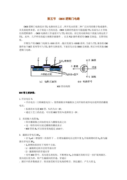
第五节CMOS逻辑门电路CMOS逻辑门电路是在TTL电路问世之后,所开发出的第二种广泛应用的数字集成器件,从发展趋势来看,由于制造工艺的改进,CMOS电路的性能有可能超越TTL而成为占主导地位的逻辑器件。
CMOS电路的工作速度可与TTL相比较,而它的功耗和抗干扰能力则远优于TTL。
此外,几乎所有的超大规模存储器件,以及PLD器件都采用CMOS艺制造,且费用较低。
早期生产的CMOS门电路为4000系列,随后发展为4000B系列。
当前与TTL兼容的CMO 器件如74HCT系列等可与TTL器件交换使用。
下面首先讨论CMOS反相器,然后介绍其他CMO 逻辑门电路。
MOS管结构图MOS管主要参数:1.开启电压V T·开启电压(又称阈值电压):使得源极S和漏极D之间开始形成导电沟道所需的栅极电压;·标准的N沟道MOS管,V T约为3~6V;·通过工艺上的改进,可以使MOS管的V T值降到2~3V。
2. 直流输入电阻R GS·即在栅源极之间加的电压与栅极电流之比·这一特性有时以流过栅极的栅流表示·MOS管的R GS可以很容易地超过1010Ω。
3. 漏源击穿电压BV DS·在V GS=0(增强型)的条件下,在增加漏源电压过程中使I D开始剧增时的V DS称为漏源击穿电压BV DS·I D剧增的原因有下列两个方面:(1)漏极附近耗尽层的雪崩击穿(2)漏源极间的穿通击穿·有些MOS管中,其沟道长度较短,不断增加V DS会使漏区的耗尽层一直扩展到源区,使沟道长度为零,即产生漏源间的穿通,穿通后,源区中的多数载流子,将直接受耗尽层电场的吸引,到达漏区,产生大的I D4. 栅源击穿电压BV GS·在增加栅源电压过程中,使栅极电流I G由零开始剧增时的V GS,称为栅源击穿电压BV GS。
5. 低频跨导g m·在V DS为某一固定数值的条件下,漏极电流的微变量和引起这个变化的栅源电压微变量之比称为跨导·g m反映了栅源电压对漏极电流的控制能力·是表征MOS管放大能力的一个重要参数·一般在十分之几至几mA/V的范围内6. 导通电阻R ON·导通电阻R ON说明了V DS对I D的影响,是漏极特性某一点切线的斜率的倒数·在饱和区,I D几乎不随V DS改变,R ON的数值很大,一般在几十千欧到几百千欧之间·由于在数字电路中,MOS管导通时经常工作在V DS=0的状态下,所以这时的导通电阻R ON可用原点的R ON来近似·对一般的MOS管而言,R ON的数值在几百欧以内7. 极间电容·三个电极之间都存在着极间电容:栅源电容C GS 、栅漏电容C GD和漏源电容CDS·C GS和C GD约为1~3pF·C DS约在0.1~1pF之间8. 低频噪声系数NF·噪声是由管子内部载流子运动的不规则性所引起的·由于它的存在,就使一个放大器即便在没有信号输人时,在输出端也出现不规则的电压或电流变化·噪声性能的大小通常用噪声系数NF来表示,它的单位为分贝(dB)·这个数值越小,代表管子所产生的噪声越小·低频噪声系数是在低频范围内测出的噪声系数·场效应管的噪声系数约为几个分贝,它比双极性三极管的要小一、CMOS反相器由本书模拟部分已知,MOSFET有P沟道和N沟道两种,每种中又有耗尽型和增强型两类。
CMOS的菜单及其设置
CMOS的菜单及其设置CMOS的菜单及其设置静态CMOS反相器互补式金属-氧化层-半导体(Complementary Metal-Oxide-Semiconductor,CMOS,简称互补式金氧半)是一种集成电路制程,可在硅晶圆上制作出PMOS(P-channel MOSFET)和NMOS(N-channel MOSFET)元件,由于PMOS与NMOS在特性上为互补性,因此称为CMOS。
此制程可用来制作微处理器(microprocessor),微控制器(microcontroller),静态随机存取内存(SRAM)与其他数位逻辑电路。
CMOS具有只有在晶体管需要切换启闭时才需耗能的优点,因此非常省电且发热少。
早期的只读内存(ROM)主要就是以这种电路制作,由于当时电脑系统的BIOS程序和参数信息都保存在ROM中,以致在很多情况下当人们提到“CMOS”时,实际上指的是电脑的BIOS 单元,而“设置CMOS”就是意指在设置BIOS。
所谓的“金属-氧化层-半导体”事实上是反映早期场效晶体管(Field-Effect Transistor,FET)的闸极(gate electrode)是由一层金属覆盖在一层绝缘体材料(如二氧化硅)所形成。
今日的金氧半场效晶体管(MOSFET)元件多已采用多晶硅(polysilicon)作为其闸极的材料,但即便如此,“金氧半”(MOS)仍然被用在现在的元件与制程名称当中。
在今日,CMOS制程经常也被用来当作数位影像器材的感光元件使用,例如高清數碼攝錄機与数码相机,尤其是片幅规格较大的数码单反相机更常见到CMOS的应用。
虽然在用途上与过去CMOS电路主要作为固件或计算工具的用途非常不同,但基本上它仍然是采取CMOS的制程,只是将纯粹逻辑运算的功能转变成接收外界光线后转化为电能,再透过芯片上的数位─类比转换器(ADC)将获得的影像讯号转变为数位讯号输出。
当微机电(MEMS)的感应元件和CMOS的讯号处理电路整合在单一芯片上时,通常称作CMOSens。
cmos密码介绍及其设置方法

cmos密码介绍及其设置方法以下是店铺为你整理的cmos密码介绍及其设置方法,供大家参考和使用。
CMOS密码首先就是CMOS密码了。
CMOS(本意是指互补金属氧化物半体存储器,是一种大规模应用于集成电路芯片制造的原料)是电脑主板上的一块可读写的RAM芯片,主要用来保存当前系统的硬件配置。
CMOS RAM芯片由系统通过一块后备电池供电,所以无论是开关机状态中,CMOS的信息都不会丢失。
既然CMOS的信息不会丢失,那么它的安全性应该是很好了。
所以,我们还是先来设置一下CMOS密码吧。
设置CMOS方法如下:1.启动计算机,在计算机正在启动时不停地按DEL键(注意,是不停地按动,而不是按住不放),直到出现CMOS SETUP界面(有的计算机进入CMOS的快捷键不是DEL,例如康柏就是F2,需要看情况而定);2.用键盘上的光标键选择SUPERVISOR PASSWORD项,然后回车,出现ENTER PASSWORD后,输入密码再回车,这时又出现CONFIRM PASSWORD,在其后再次输入同一密码(注:该项原意是对刚才输入的密码进行校验,如果两次输入的密码不一致,则会要求你重新输入);3.用光标键选择USER PASSWORD项后回车,同上面一样,密码需输入两次才能生效。
以上设置的两个密码分别为设置密码和修改CMOS SETUP密码,建议两个均取同一密码,以便记忆;4.选择DIOS FEATURES SETUP项回车,用光标键选择SECURITY OPION项后用键盘上的PAGE UP/PAGE DOWN键把选项改为SYSTEM(设定为SYSTEM的目的是让计算机在任何时候都要检测密码,包括启动机器),然后按ESC键退出;5.选择SAVE&EXIT SETUP项回车,出现提示后按Y键再回车,以上设置的密码即可生效。
听说COMS密码的安全性不是很高,有很多种方法可以解除,先不管那么多了,就当这是第一重障碍吧。
- 1、下载文档前请自行甄别文档内容的完整性,平台不提供额外的编辑、内容补充、找答案等附加服务。
- 2、"仅部分预览"的文档,不可在线预览部分如存在完整性等问题,可反馈申请退款(可完整预览的文档不适用该条件!)。
- 3、如文档侵犯您的权益,请联系客服反馈,我们会尽快为您处理(人工客服工作时间:9:00-18:30)。
A Multi-Stage CMOS Charge Pump for Low-Voltage Memories Young-Hee Kim1, Gyu-Ho Lim1, Sung-Han Yoo1, Mu-Hun Park1, Bong-Jin Ko1, Seong-Ik Cho2 ,Kyeong-Sik Min3, Jin-Hong Ahn2, Jin-Yong Chung21Department of Electronic Engineering, Changwon National University, Koreae-mail : youngkim@sarim.changwon.ac.kr2Memory R&D Division, Hynix Semiconductor Inc., Korea3Institute of Industrial Science, University of Tokyo, JapanAbstract: To remedy both the degradation and saturation of the output voltages in the modified Dickson pump, a new multi-stage charge pump circuit is presented in this paper. Here using PMOS charge-transfer switches instead of NMOS ones eliminates the necessity of diode-configured output stage in the modified-Dickson pump, achieving the improved voltage pumping gain and its output voltages proportional to the stage numbers. Measurement indicates that VOUT/3VDD of this new pump circuit with two stages reaches to a value as high as 0.94V even with low VDD=1.0 V, strongly addressing that this scheme is very favorable at low-voltage memory applications.1. IntroductionMulti-stage charge pumps have been investigated for many years since they can generate higher voltages than supply voltage (VDD) that are used in programming and erasing in nonvolatile memories such as EEPROMs. In addition, they can also be used in programming the antifuses for post-package fail-bit repair scheme in recent high-density DRAMs [1]. Most MOS charge pumps are based on the circuit proposed by J. Dickson that comprises the diode-configured switches and the pumping capacitors controlled by two out-of-phase clocks (CLK and CLKB) [2]. However, since its voltage pumping gain is significantly reduced with VDD decreasing, some modifications have been carried out to alleviate this gain reduction [3].One of these modified Dickson pumps is using high-voltage-driven charge-transfer switches that do not lose the pumping voltages, as proposed in NCP-2 scheme in [3]. An example of NCP-2 with two stages is shown in Figure 1, where MD’s are the diode-configured transfer switches and MS’s are the charge-transfer switches. MN’s and MP’s are the control switches that control the gates of the charge-transfer switches dynamically, respectively, and C1, C2, and C3 are the pumping capacitors. CLK and CLKB are representing two out-of-phase clocks and VOUT is the output voltage at the load capacitor CL. As stated earlier, using high voltage-driven charge-transfer switches in parallel with diode-configured switches as shown in Figure 1 can eliminate the sacrificial voltage loss when they deliver the generated voltages into the next nodes. However, NCP-2 scheme in Fig. 1 still suffers from the threshold voltage loss due to the diode configuration at the output stage. As shown in Fig. 1, MD0 loses the pumping voltage by a voltage as large as V TH (threshold voltage) of MD0. This degrades the voltage pumping gain especially at low-VDD operation. This can be seen in Fig. 6, where straight line is corresponding to highest voltages that can be generated by charge pump and symbols of solid-circle show voltages generated by NCP-2 in Fig.1. When the stage number is two, 3VDD is highest voltage to generate. In Fig. 6, VOUT/3VDD is 0.7 when VDD is 2.4V and VOUNT/3VDD is 0.55 when VDD is 0.6V, indicating that the degradation of VOUT becomes severe with decreasing VDD. Another problem of NCP-2 is that the output voltages of NCP-2 scheme begin to saturate after they reach to around 7 V in spite of increasing the stage number, as shown in Fig. 7. This also is due to the constraint imposed by its diode-configured output stage, as shown in Fig. 1.To remedy both the degradation and saturation of the output voltage in NCP-2, we propose a new multi-stage charge pump circuit in this paper. Here using PMOS charge-transfer switches instead of NMOS ones eliminates the necessity of diode-configured output stage in NCP-2, achieving improved voltage pumping gain and output voltage proportional to the stage number. Moreover, the pumping efficiency of the new charge pump can be improved by using non-overlapping two-phase clocks. At the following section, operations of NCP-2 scheme in Fig. 1 and newly proposed scheme will be explained. At the section 3, comparisons of NCP-2 and this new scheme will be done by HSPICE simulation. And, measured results of this new scheme will also be shown. At the final section 4, we will conclude this paper.2. Circuit Confugurations and their OperationsFirst of all, let us see the operation of NCP-2 in Fig.1 in detail. Unlike the conventional Dickson c harge pump having only the diode-configured switches [2], NCP-2 scheme has the charge-transfer switches of MS1 and MS2 that are controlled dynamically via MN1, MN2, MP1, and MP2, in addition to the conventional diode-configured switches MD1 and MD2 [3], as shown in Fig. 1. Let us assume that CLK1 goes low and CLK2 goes high. At this moment, a voltage on the node N2 goes 3VDD and a voltage on the node N1 goes VDD, turning on MP1 and turning off MN1, respectively. Since the charge-transfer switch MS1 being controlled by a voltage on the node N2 via MP1 that is internally boosted, is fully turned on, it can deliver a voltage of VDD into the next node N1 without a voltage loss. Simultaneously, a voltage on the node N2 being boosted to have a value of 3VDD, is delivered to the next node of VOUT via the diode-configured MD0. It should be noted here that a voltage loss as much as VTH of MD0 occurs at MD0, degrading the voltage pumping gain of NCP-2, as already addressed at the section 1.One more thing to note here is that a voltage on node N5 also is lowered by as much as the threshold voltage of MD3. This sacrificial voltage loss gives rise to the saturation of VOUT’s especially when the stage number becomes large. To know why the saturation of VOUT’s occurs in NCP-2, let us assume that CLK1 goes high and CLK2 goes low. At this moment, a voltage on the node N5 goes 4VDD-VTH(MD3) and a voltage on the node N2 goes 2VDD. Here VTH(MD3) means the threshold voltage of MD3 in Fig. 1. If V(N5)-V(N2) is large enough to turn on MP2, the gate of MS2 is controlled by the voltage on the node N5 via MP2. Here V(N5) and V(N2) mean voltages on the nodes N5 and N2, respectively. To turn on MS2 fully, V(N5)-V(N1) should be larger than VTH(MS2). Since VTH(MS2) is the threshold voltage under severe body-effect and is though to be a little larger than an absolute value of VTH(MP2) with the body and source voltages tied to each other, it gives more severe constraint in generating VOUT than VTH(MP2). In Fig. 7, you can see that VOUT’s begin to saturate around 7V even with increasing the stage number more. This is due to the constraint of VTH(MS2) that comes from the diode-configured MD3. To remedy this saturation of VOUT’s with increasing the stage number, NCP-3 with the output stage driven by boosted clock with a magnitude of 2VDD has been suggested in [3]. Though NCP-3 shows that its output voltage is proportional to the stage number, NCP-3 has the more severe gate-oxide stress than NCP-2 in Fig. 1 and requires an auxiliary double-boosted clock generator. In NCP-3, a voltage on the node N5 can reach to as high as 5VDD-VTH, while it is only 4VDD-VTH in NCP-2 as shown in Fig. 2.To remedy both the degradation and saturation of the output voltage in NCP-2, we propose a new multi-stage charge pump circuit in this paper. Here using PMOS charge-transfer switches instead of NMOS’s eliminates the necessity of diode-configured output stage in NCP-2, remedying the drawbacks in NCP-2 stated earlier. A voltage doubler where PMOS charge-transfer switches are used to avoid the threshold voltage loss of NMOS transfer switches has already been proposed [4]. Though PMOS switches can deliver the generated voltages to the load without losses, simultaneously, PMOS switches with higher voltages on their sources than their substrate voltages can lose pumped charges into the parasitic pnp bipolars [4]. To avoid those turning-on’s, a doubler where the substrates of PMOS charge-transfer switches are controlled by small-auxiliary PMOS bulk switches to have higher voltages than their source voltages always, has been presented [4].Fig. 3 shows a simple block-diagram of the proposed 2-stage charge pump circuit using PMOS charge-transfer switches. It consists of a main pump block and an auxiliary pump block. And each of them includes a power-up precharge circuit, a pump control circuit, and an output stage. The power-up precharge circuit sets up the first-stage pumping nodes to have voltages of VCC [5]. And, the role of the auxiliary pump is that the substrates of PMOS charge-transfer switches have higher voltages than their sources, as stated just earlier. The auxiliary pump block has the same scheme with the main pump block but sizes of the switches are much smaller than the main pump block.More detailed scheme is shown in Fig. 4. Here two power-up precharge circuits (PPC) consist of MP0, MP1, MP2, MP3, MN0, and MN1 that are controlled by two-non-overlapping clocks CLK0 and CLK3. C1, C2, C3, and C4 represent the pumping capacitors that are controlled by two clocks CLK1 and CLK2. MP4, MP5, MP6, MP7, MN2, and MN3 control the PMOS charge-transfer switches of MP6 and MP7. MP8 and MP9 deliver the generated voltages into the output load capacitor CL. In Fig. 4, four clocks are used. The detailed waveforms of nodes and 4 clocks are shown in Fig. 5. To simplify the circuit diagram, the auxiliary pump circuit is represented by a box. As stated earlier, the auxiliary pump is the same with the main pump shown in Fig. 4 but only the sizes are different.Now let us see the operation of the power-up precharge circuit in Fig. 4. When CLK0 goes low and CLK1 goes high, MN0 is turned off and MP1 is turned on. At this moment, a voltage on the node N2 becomes 2VDD and turns off MP0 via MP1. At the other side, CLK2 goes low and CLK3 goes high, turning on MN1 and turning off MP3. At this time, since MP2 is turned on via MP3, the node N3 is precharged by a voltage of VDD. The operation of the main pump circuit to fully turn on the gates of the charge-transfer switches of MP6 and MP7 is as follows. When CLK1 goes high and CLK2 goes low, voltages on the nodes N2, N3, N4 and N5 are 2VDD, VDD, 2VDD and 3VDD, respectively. If a voltage of VDD is larger than the threshold voltages of PMOS and NMOS, a voltage on the node N6 becomes VDD via MN2 and a voltage on the node N7 becomes 3VDD via MP5. Thus, a voltage on the node N4 becomes the same with a voltage on the node N2 via MP6 turned on, and a voltage on the node N5 is separated from a voltage on the node N3 via MP7 turned off. At this moment, a boosted voltage of 3VDD on the N5 is fully delivered to the output without the threshold voltage loss via MP9 that is turned on by a voltage of 2VDD on the node N4.On the other hand, when CLK1 goes low and CLK2 goes high, voltages on the nodes N2, N3, N4 and N5 ar e VDD, 2VDD, 3VDD and 2VDD, respectively. At this moment, MP6 is turned off via MP4 and MP7 is turned on via MN3. A boosted voltage of 3VDD on the node N4 is delivered to the output load without the loss, as the same with when CLK1 is high and CLK2 is low.3. Simulation and MeasurementTo verify the operation of the proposed circuit, HSPICE simulation with a 0.12-?m triple-well CMOS technology was performed. Fig. 6 shows the output voltages of the proposed circuit compared with the modified Dickson pump (NCP-2) in a VDD range of 0.0V-2.5V. This figure clearly shows that the proposed charge pump circuit can generate higher voltages than the modified Dickson pump (NCP-2). In Fig. 7, the output voltages of the proposed circuit and the modified Dickson pump a re compared with increasing the stage number (N). Here it can be seen that the output voltage of the proposed circuit is proportional to the stage number (N) without indicating any saturation. Fig. 8 shows output voltages of the 2-stage new pump shown in Figure 4 with varying VDD. This figureindicates that almost 3VDD can be generated by using newly proposed pump scheme in Figure 4 with two stages when VDD ranges from 1V to 1.75V. The degradation of VOUT’s is observed in Fig. 8, since the fabrication process does not support high-voltage tolerable CMOS devices.4. ConclusionTo remedy both the degradation and saturation of the output voltages in the modified Dickson pump, a new multi-stage charge pump circuit is presented in this paper. This new pump using PMOS charge-transfer switches instead of NMOS ones achieves improved voltage pumping gain and its output voltages are shown to be proportional to the stage numbers unlike the previous modified Dickson pump. Measurements and simulations indicate that this new pump is very favorable in particular at low VDD applications.AcknowledgementsThis work was supported by grant No. (R 05-2002-000-00726-0) from the Basic Research Program of the Korea Science & Engineering Foundation. The authors are thankful to IDEC(IC Design Education Center) for the support of hardware and design software.References[1] J.-K. Wee et al., “An antifuse EPROM circuitry schemefor field -programmable repair in DRAM”, IEEE Journal of Solid-State Circuits,, vol. 35, no. 10, pp. 1408-1414, Oct. 2000.[2] J. F. Dickson, “On-chip high-voltage generation in NMOS integrated circuits using an improved voltage multiplier technique,” IEEE J. Solid-State Circuits, vol. 11, pp. 374-378, June 1976.[3] J. T. Wu and K.-L. Chang, “MOS charge pump for low-voltage operation,” IEEE J. Solid-State Circuits, vol. 33, pp. 592-597, Apr. 1998.[4] P. Favrat, P. Deval and M.J. Declercq, “A High-Efficiency CMOS Voltage Doubler,” IEEE J. Solid-StateFig. 2. Waveforms of the modified Dickson pump circuit (NCP-2) shown in Fig. 1.Fig. 3. Simple block diagram of newly proposed pump circuit with 2 stages.Fig. 5. Waveforms of the signals that are shown in Fig. 4.Fig. 6. Output voltages of the 2-stage modified Dickson pump (NCP-2) shown in Fig. 1 and the 2-stage new pump shown in Fig. 4 with varying VDD. The conventional circuit in this figure represents NCP-2 scheme in [3].Fig. 7. Output voltages of the 2-stage modified Dickson pump (NCP-2) shown in Fig. 1 and the 2-stage new pump shown in Fig. 4 with varying the stage number (N). The conventional circuit in this figure represents NCP-2 scheme in [3].V o u t [V ]VDD[V]Fig. 8. Output voltages of the 2-stage new pump shown in Figure 4 with varying VDD. This figure indicates that almost 3VDD can be generated by using newly proposed pump scheme in Figure 4 with two stages when VDD ranges from 1V to 1.75V.。
