EMC BRS and RecoverPoint training Training
EMC_RecoverPoint介绍

Various application processes . . . . . .
Listen for Log Request, collect and transfer to RPA over IP
HBA
HBA
NIC
© 版权所有 2009 EMC Corporation。保留所有权利。
12
Fabric-Based Write Splitters
8
WAN 带宽节约
管理员设置重要性和 RPO 策略 管理员指定带宽消耗策略 RecoverPoint 监视带宽并优化资源利用率
中午 12:00 早晨 6:00 下午 6:00 中午 12:00
源 CG1 更新 更新
目标 CG1
20 分钟 RPO
10 Mb/s
源 CG2 更新 更新
3 Mb/s
*AIX and Solaris host-based write splitters are not supported by RecoverPoint/SE
Partition Manager
Kshsplit.sys
Multipath Driver Disk Class Driver (e.g., Disk.sys) HBA Miniport/ Storport Driver
10 Mb/s
目标 CG2
6 分钟 RPO
在 RecoverPoint/SE 外部 更改带宽
源阵列
© 版权所有 2009 EMC Corporation。保留所有权利。
目标阵列
9
RecoverPoint 管理
使用单一界面复制 SAN 连接的 卷
本地和/或远程监视和管理复制 设置和修改复制策略 与 VMware vCenter Site Recovery Manager 和 vCenter 集成;支持 Microsoft Hyper-V 包括在线帮助 按应用程序向用户授权 包括自动化向导 还提供命令行界面 (CLI)
(答案)NCC阶段考核试题(一)(含答案)
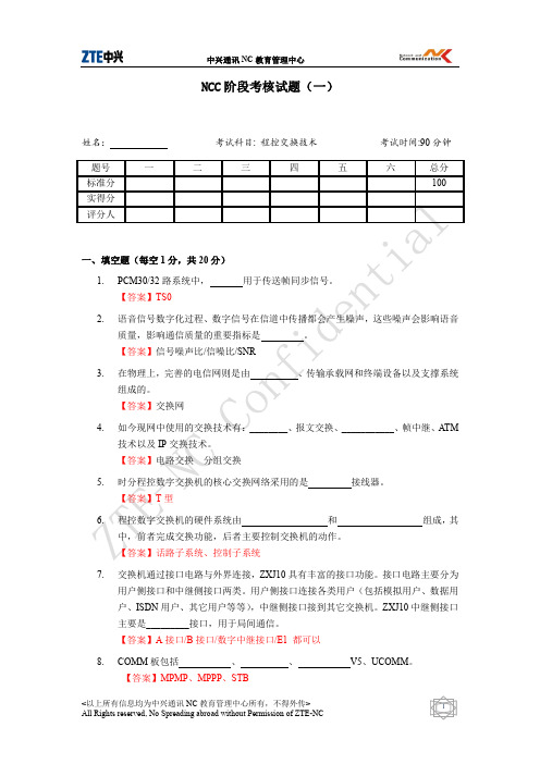
______ 个 模 块 , 其 中 外 围 交 换 模 块 最 多
11. 近端模块可以通过
、
、
【答案】FBI、ODT、DTI、MDT、SDT
等与上级模块相连。
12. 每块 ASLC 板含 【答案】24
路模拟用户,每块 DSLC 板 12 路数字用户。
13. 按钮话机一般就接双音多频收号器,ZXJ10 设备中 能。 【答案】ASIG
8. 前台主备用 MP 的拨码开关设置一致,IP 节点号也一致。( F )
9. MP 级的 DSNI 板和 SP 级的 DSNI 板可以随便互换,不需任何改变。( F )
10. 时钟单元通过 SYCK 板从 DTI、FBI 提取时钟。( T )
五、简答题(每题 5 分,共 20 分) 1. 简述电路交换、报文交换、分组交换的特点。 【答案】电路交换是指呼叫双方在开始通话之前,必须先由交换设备在两者之间建 立一条专用电路,并在整个通话期间由他们独占这条电路,直到通话结束为止的一 种交换方式。电路交换的优点是实时性好、传输时延很小,特别适合象话音通信之 类实时通信场合。 报文交换又称为消息交换,用于交换电报、信函、文本文件等报文消息。在报文交 换网中,一条报文所经由的网内路径只有一条,但相同的源点和目的点间传送的不 同报文可能会经由不同的网内路径。 分组交换,消息被划分为一定长度的数据分组(也称数据包)。一报文的各个分组 可能经过不同的路径到达终点,由于中间节点的存储时延不一样,各分组到达终点 的先后与源节点发出的顺序可能不同。因此目的节点收齐分组后尚需先经排序、解 包等过程才能将正确的数据送给用户。
<以上所有信息均为中兴通讯 NC 教育管理中心所有,不得外传>
4
All Rights reserved, No Spreading abroad without Permission of ZTE-NC
EMCRecoverPoint测试
EMC 证券业RecoverPoint-容灾测试为了切实验证EMC公司的RecoverPoint产品方案在证券行业核心交易系统与数据中心等环境的使用方法和方案价值,验证其技术和功能能够满足XX相关应用系统的实际需求,特别是要符合证券与基金的行业规范(如中国证监会发布的《证券期货经营机构信息系统备份能力标准》等)和治理指引,并对其特点和各项功能进行更深入的了解,由XX进行数据容灾模拟测试。
本次测试准备事项:1)EMC公司提供RecoverPoint设备和软件、CX存储设备(或VNX产品),SAN交换机(可选);2)测试服务器两台,光纤线若干,SAN环境准备;3)测试服务器提前准备安装数据库与交易测试软件;本次测试的主要目标包括:1)测试EMC RecoverPoint灾备系统的连续备份能力。
2)综合测试EMC RecoverPoint灾备系统在主机系统故障(例如硬盘故障或数据丢失,数据损坏、SAN网络中断等)时的容灾备份能力。
3)综合测试EMC RecoverPoint灾备系统在本地系统故障(例如硬盘故障或数据丢失,数据损坏、、SAN网络中断等)时的灾备系统恢复能力。
4)测试EMC RecoverPoint容灾系统是否方便数据校验,及校验过程中演习对容灾系统有什么影响。
5)专测EMC RecoverPoint帮助本地环境(不切换主机)下SQL/Oracle数据库故障恢复;6)专测在EMC RecoverPoint帮助容灾环境(切换主机)下SQL/Oracle数据库故障恢复测试;7)测试EMC RecoverPoint灾备份环境下业务切换接管时间(注:未来允许的话,可考虑金证软件直接调用RP命令或脚本,提高两者融合程度,加速切换时间)。
本测试报告将对各项测试的步骤和结果予以记录。
1.测试环境准备示意图2.测试系统架构描述2.1硬件架构描述2.2软件架构描述2.3测试环境描述(1)数据库服务器两台,各带HBA连接到SAN环境;(2)SAN交换机两台,检查有足够空余端口;(3)RecoverPoint应用装置一或两套;(4)一或两台测试存储CX4/VNX(待定),选用FAST Suit(建议配置EFD);3.测试安排3.1 测试人员组成3.2 测试时间2011年(待定)3.3 测试地点4.测试内容及过程(备注:如果时间与测试条件允许,可增加测试基于FATS Suit的自动数据分层优化功能。
SIPIEMC基础学习

Electro Magnetic Compatibility)。
Signalintegrity⚫Reflection⚫Delay⚫Cross talk⚫jitterPower integrity⚫SSO/SSN⚫Plain resonanceSI/PI/EMC问题根源➢PCB板上有各种各样粗细,长短不一的连接走线,在信号传输速率比较低的时候,一段线路的表现仅为连通,只是电性连通作用,而当传输速率增大到一定程度,这段线路就会产生寄生电阻/电容效应,继续增大速率,表现出传输线效果,甚至是类似天线的效果,将电磁能量辐射出去,PCB的主要作用是传输能量而非传输能量,所以不希望PCB工作过程中表现出天线的效果。
转角频率➢当信号源传输高频信号时,由于信号线与返回路径或地线产生互感/互容作用,信号会通过这些作用及时返回,此时导线不再是简单的连通作用,变为一段传输线,将传输线等效为RLGC电路,一段长度的电路上通常不能简单的视为一个RLGC电路,而是有若干个RLGC电路组成,称为分布式RLGC。
➢传输线最小单元, 一个RLGC电路内的阻抗称为特征阻抗Z0,一般R和G较小,忽略,所以Z与L/C值有直接关系,即与传输线的线宽/厚度,介质层的介质损耗/介电常数,以及信号线与地线的距离相关,与线长关系不大,所以阻抗设计主要是设计线宽,距离及所使用的的材料。
R:导体中的例子和趋肤效应造成的电流损耗L:电流会在导线周围激发磁场C:信号路径和返回路径之间聚集了不同电荷G:信号路径和回流路径之间的介质因为极化效应产生的损耗➢微带线:信号只有一个参考层,即PCB表层,Top和bottom层的走线结构➢带状线:信号有两个参考层,中间是信号传输结构,即PCB内部走线结构➢传输线反射系数⚫当传输线的传播信号到达某个阻抗不连续点(线宽不一致、过孔等),信号会发生反射,就像水流通过不同口径的管道接口时,水面产生波动一样。
为了描述这种反射线,定义了一个参数叫反射系数(r),根据反射电压(Vref)和入射电压(Vinc ),可以定义传输线上的反射系数。
EMC recoverpoint 连续数据容灾与保护解决方案

• VNX、VMAX Ralf Rossol
解决方案
应用程序
结果
• 借助虚拟化实现扩展,满足了应对大数据增长的需求 • 显著提升了性能和数据可用性 • 借助 VMware 和快速资源调配缩短了上市时间
© 版权所有 2013 EMC Corporation。保留所有权利。
21
可靠性、性能和易用性
Brainshark 借助 VNX 和 RecoverPoint 提供按需服务
VPLEX RecoverPoint 远程 RecoverPoint 本地 本地
远程
© 版权所有 2013 EMC Corporation。保留所有权利。
6
任何位置的 RecoverPoint 多站点复制功能
支持多站点冗余需求
同步和异步连续本地/远程复制 借助数据压缩、重复数据消除技术和通过 IP 的同步复制,减少高达 90% 的带宽
“鉴于数据丢失 事件可能导致经 济损失,因此将 重点放在数据保 护上是有意义 的。”
备份和恢复解决方案 针对异地灾难恢复的数据复制解决方案 购买新的 SAN 存储系统 改善存储管理软件工具 存储虚拟化 购买能效更高的存储硬件 数据减少技术 使用云存储服务 分层存储 购买新的 NAS 存储系统
36%
24%
使用不灵活且为数极少的方式 访问上一时间点的数据
即时访问不同时间点的 早期版本数据
© 版权所有 2013 EMC Corporation。保留所有权利。
9
复制功能的使用日益增多
“各种规模的组织在数据保护方案中越来越多地采用复 制功能作为其第一道防线。”
— IDC 分析家 Eric Sheppard
IT • 总监 FAST Suite
基于YOLOv5s的轻量化行人检测算法
现代电子技术Modern Electronics TechniqueNov. 2023Vol. 46 No. 222023年11月15日第46卷第22期0 引 言行人检测一直都是计算机视觉和目标检测领域的研究热点,其广泛应用于人群计数、智能安防、自动驾驶等应用领域。
目前存在的行人检测算法已经取得较好的检测效果,但依然面临一些挑战,比如:行人检测识别系统普遍都安装在智能汽车和无人机等移动端智能平台中,对模型轻量化要求较高,然而已有算法很难在轻量化和精度上达到平衡,因此提高行人检测精度的同时保持模型轻量化有着重要的研究意义。
常用的行人检测方法主要分为传统行人检测方法和基于深度学习的行人检测方法两大类。
基于深度卷积神经网络的目标检测算法主要分为单阶段算法和双阶段算法[1]。
其中双阶段算法是基于候选框的方法,代表算法主要有R⁃CNN [2]、Fast R⁃CNN [3]、Faster R⁃CNN [4]等,该类算法精度较高,但检测速度较慢;单阶段算法是基于回归的方法,不再提取候选区域,代表算法主要有SSD (Single Shot MultiBox Detector )[5]系列、YOLO (You Only Look Once )[6⁃9]系列等,该类算法检DOI :10.16652/j.issn.1004⁃373x.2023.22.026引用格式:高英,吴玉虹.基于YOLOv5s 的轻量化行人检测算法[J].现代电子技术,2023,46(22):151⁃158.基于YOLOv5s 的轻量化行人检测算法高 英, 吴玉虹(昆明理工大学 信息工程与自动化学院, 云南 昆明 650500)摘 要: 行人检测系统普遍安装在移动智能设备上,而这些设备对模型的轻量化要求较高,已有算法很难在精度和轻量化之间达到平衡。
针对这一问题,提出一种改进的YOLOv5s 轻量化行人检测模型。
选用EIoU 作为边界框损失函数,加速收敛并提高回归精度;结合CA (Coordinate Attention )注意力模块改进主干网络的C3模块,增强模型对行人目标的精确定位能力;引入一种新卷积层GSConv 替换颈部网络的卷积层(Conv ),以减轻模型的复杂度并保持准确性;引入改进的自注意力模块CoT ,进一步提高网络模型的特征表达能力。
Lenovo EMC存储方案介绍

16 GB
32GB 1.8 GHz, Sandy Bridge 4 个核心
16 GB
32GB 1.8 GHz, Sandy Bridge 4 个核心
24 GB
48GB 2.4 GHz, Sandy Bridge 4 个核心
32 GB
64GB 2.0 GHz, Sandy Bridge 6 个核心
− 提高性能; − 隔离故障域; 无论出现何种故障都能实现零 RTO;− 更易于管理。 −
18
EMC VPLEX 产品特性——协作性
在不同的位置同时使用数据;
一个拷贝 — 始终最新; 立即可用; 无管理开LEX Local在本地数据中心使用,可跨数据中心内的异构阵列提供简化管理和无中断的数据移动能力; VPLEX Metro在两个数据中心使用,提供同步距离内两个VPLEX群集间的数据访问和移动性; VPLEX Geo能在异步距离内的两个或两个以上的VPLEX群集之间访问和移动数据,进一步打破数据中心 之间的距离障碍; VPLEX Global将彻底打破数据中心之间的距离障碍,使得跨国信息协作成为可能。
• • • •
专为中小型用户设计,简单易用 简单的向导驱动资源调配 控制器架构的NAS、IPSAN存储 入门级价格轻松拥有
全面的数据管理和保护
令人放心且不增加复杂性
软件套件
软件包
VNXe3150
Security and Compliance Suite
版本完整性和审计就绪性
Local Protection Suite
VNX-5150
V-MAX
VNX-5200
5
定制独销 + OEM +Reseller
3GPP协议-36521-1-e40_s00-s05
3GPP TS 36.521-1 V14.4.0 (2017-09)Technical Specification3rd Generation Partnership Project; Technical Specification Group Radio Access Network; Evolved Universal Terrestrial Radio Access (E-UTRA);User Equipment (UE) conformance specification;Radio transmission and reception;Part 1: Conformance Testing(Release 14)The present document has been developed within the 3rd Generation Partnership Project (3GPP TM) and may be further elaborated for the purposes of 3GPP.KeywordsUMTS LTE3GPPPostal address3GPP support office address650 Route des Lucioles - Sophia AntipolisValbonne - FRANCETel.: +33 4 92 94 42 00 Fax: +33 4 93 65 47 16InternetCopyright NotificationNo part may be reproduced except as authorized by written permission.The copyright and the foregoing restriction extend to reproduction in all media.© 2017, 3GPP Organizational Partners (ARIB, ATIS, CCSA, ETSI, TSDSI, TTA, TTC).All rights reserved.UMTS™ is a Trade Mark of ETSI registered for the benefit of its members3GPP™ is a Trade Mark of ETSI registered for the benefit of its Members and of the 3GPP Organizational Partners LTE™ is a Trade Mark of ETSI registered for the benefit of its Members a nd of the 3GPP Organizational Partners GSM® and the GSM logo are registered and owned by the GSM AssociationContentsForeword (92)Introduction (92)1Scope (93)2References (94)3Definitions, symbols and abbreviations (96)3.1Definitions (96)3.2Symbols (98)3.3Abbreviations (100)4General (103)4.1Categorization of test requirements in CA, UL-MIMO, ProSe, Dual Connectivity, UE category 0, UEcategory M1, UE category 1bis, UE category NB1 and V2X Communication (104)4.2RF requirements in later releases (105)5Frequency bands and channel arrangement (106)5.1General (106)5.2Operating bands (106)5.2A Operating bands for CA (108)5.2B Operating bands for UL-MIMO (116)5.2C Operating bands for Dual Connectivity (116)5.2D Operating bands for ProSe (117)5.2E Operating bands for UE category 0 and UE category M1 (118)5.2F Operating bands for UE category NB1 (118)5.2G Operating bands for V2X Communication (118)5.3TX–RX frequency separation (119)5.3A TX–RX frequency separation for CA (120)5.4Channel arrangement (120)5.4.1Channel spacing (120)5.4.1A Channel spacing for CA (121)5.4.1F Channel spacing for UE category NB1 (121)5.4.2Channel bandwidth (121)5.4.2.1Channel bandwidths per operating band (122)5.4.2A Channel bandwidth for CA (124)5.4.2A.1Channel bandwidths per operating band for CA (126)5.4.2B Channel bandwidth for UL-MIMO (171)5.4.2B.1Channel bandwidths per operating band for UL- MIMO (171)5.4.2C Channel bandwidth for Dual Connectivity (171)5.4.2D Channel bandwidth for ProSe (171)5.4.2D.1Channel bandwidths per operating band for ProSe (171)5.4.2F Channel bandwidth for category NB1 (172)5.4.2G Channel bandwidth for V2X Communication (173)5.4.2G.1Channel bandwidths per operating band for V2X Communication (173)5.4.3Channel raster (174)5.4.3A Channel raster for CA (175)5.4.3F Channel raster for UE category NB1 (175)5.4.4Carrier frequency and EARFCN (175)5.4.4F Carrier frequency and EARFCN for category NB1 (177)6Transmitter Characteristics (179)6.1General (179)6.2Transmit power (180)6.2.1Void (180)6.2.2UE Maximum Output Power (180)6.2.2.1Test purpose (180)6.2.2.4Test description (182)6.2.2.4.1Initial condition (182)6.2.2.4.2Test procedure (183)6.2.2.4.3Message contents (183)6.2.2.5Test requirements (183)6.2.2_1Maximum Output Power for HPUE (185)6.2.2_1.1Test purpose (185)6.2.2_1.2Test applicability (185)6.2.2_1.3Minimum conformance requirements (185)6.2.2_1.4Test description (185)6.2.2_1.5Test requirements (186)6.2.2A UE Maximum Output Power for CA (187)6.2.2A.0Minimum conformance requirements (187)6.2.2A.1UE Maximum Output Power for CA (intra-band contiguous DL CA and UL CA) (189)6.2.2A.1.1Test purpose (189)6.2.2A.1.2Test applicability (189)6.2.2A.1.3Minimum conformance requirements (189)6.2.2A.1.4Test description (189)6.2.2A.1.5Test Requirements (191)6.2.2A.2UE Maximum Output Power for CA (inter-band DL CA and UL CA) (192)6.2.2A.2.1Test purpose (192)6.2.2A.2.2Test applicability (192)6.2.2A.2.3Minimum conformance requirements (192)6.2.2A.2.4Test description (192)6.2.2A.2.5Test Requirements (194)6.2.2A.3UE Maximum Output Power for CA (intra-band non-contiguous DL CA and UL CA) (196)6.2.2A.4.1UE Maximum Output Power for CA (intra-band contiguous 3DL CA and 3UL CA) (196)6.2.2A.4.1.1Test purpose (196)6.2.2A.4.1.2Test applicability (196)6.2.2A.4.1.3Minimum conformance requirements (196)6.2.2A.4.1.4Test description (196)6.2.2A.4.1.5Test Requirements (198)6.2.2A.4.2UE Maximum Output Power for CA (inter-band 3DL CA and 3UL CA) (198)6.2.2A.4.2.1Test purpose (199)6.2.2A.4.2.2Test applicability (199)6.2.2A.4.2.3Minimum conformance requirements (199)6.2.2A.4.2.4Test description (199)6.2.2A.4.2.5Test Requirements (201)6.2.2B UE Maximum Output Power for UL-MIMO (201)6.2.2B.1Test purpose (201)6.2.2B.2Test applicability (202)6.2.2B.3Minimum conformance requirements (202)6.2.2B.4Test description (204)6.2.2B.4.1Initial condition (204)6.2.2B.4.2Test procedure (205)6.2.2B.4.3Message contents (205)6.2.2B.5Test requirements (205)6.2.2B_1HPUE Maximum Output Power for UL-MIMO (207)6.2.2B_1.1Test purpose (207)6.2.2B_1.2Test applicability (207)6.2.2B_1.3Minimum conformance requirements (207)6.2.2B_1.4Test description (207)6.2.2B_1.5Test requirements (208)6.2.2C 2096.2.2D UE Maximum Output Power for ProSe (209)6.2.2D.0Minimum conformance requirements (209)6.2.2D.1UE Maximum Output Power for ProSe Discovery (209)6.2.2D.1.1Test purpose (209)6.2.2D.1.2Test applicability (209)6.2.2D.1.3Minimum Conformance requirements (209)6.2.2D.2UE Maximum Output Power for ProSe Direct Communication (211)6.2.2D.2.1Test purpose (211)6.2.2D.2.2Test applicability (211)6.2.2D.2.3Minimum conformance requirements (211)6.2.2D.2.4Test description (211)6.2.2E UE Maximum Output Power for UE category 0 (212)6.2.2E.1Test purpose (212)6.2.2E.2Test applicability (212)6.2.2E.3Minimum conformance requirements (212)6.2.2E.4Test description (212)6.2.2E.4.3Message contents (213)6.2.2E.5Test requirements (213)6.2.2EA UE Maximum Output Power for UE category M1 (215)6.2.2EA.1Test purpose (215)6.2.2EA.2Test applicability (215)6.2.2EA.3Minimum conformance requirements (215)6.2.2EA.4Test description (216)6.2.2EA.4.3Message contents (217)6.2.2EA.5Test requirements (217)6.2.2F UE Maximum Output Power for category NB1 (218)6.2.2F.1Test purpose (218)6.2.2F.2Test applicability (218)6.2.2F.3Minimum conformance requirements (218)6.2.2F.4Test description (219)6.2.2F.4.1Initial condition (219)6.2.2F.4.2Test procedure (220)6.2.2F.4.3Message contents (220)6.2.2F.5Test requirements (220)6.2.2G UE Maximum Output Power for V2X Communication (221)6.2.2G.1UE Maximum Output Power for V2X Communication / Non-concurrent with E-UTRA uplinktransmission (221)6.2.2G.1.1Test purpose (221)6.2.2G.1.2Test applicability (221)6.2.2G.1.3Minimum conformance requirements (221)6.2.2G.1.4Test description (222)6.2.2G.1.4.1Initial conditions (222)6.2.2G.1.4.2Test procedure (222)6.2.2G.1.4.3Message contents (222)6.2.2G.1.5Test requirements (223)6.2.2G.2UE Maximum Output Power for V2X Communication / Simultaneous E-UTRA V2X sidelinkand E-UTRA uplink transmission (223)6.2.2G.2.1Test purpose (223)6.2.2G.2.2Test applicability (223)6.2.2G.2.3Minimum conformance requirements (223)6.2.2G.2.4Test description (224)6.2.2G.2.4.1Initial conditions (224)6.2.2G.2.4.2Test procedure (225)6.2.2G.2.4.3Message contents (226)6.2.2G.2.5Test requirements (226)6.2.3Maximum Power Reduction (MPR) (226)6.2.3.1Test purpose (226)6.2.3.2Test applicability (226)6.2.3.3Minimum conformance requirements (227)6.2.3.4Test description (227)6.2.3.4.1Initial condition (227)6.2.3.4.2Test procedure (228)6.2.3.4.3Message contents (228)6.2.3.5Test requirements (229)6.2.3_1Maximum Power Reduction (MPR) for HPUE (231)6.2.3_1.1Test purpose (231)6.2.3_1.4Test description (232)6.2.3_1.5Test requirements (232)6.2.3_2Maximum Power Reduction (MPR) for Multi-Cluster PUSCH (232)6.2.3_2.1Test purpose (232)6.2.3_2.2Test applicability (232)6.2.3_2.3Minimum conformance requirements (233)6.2.3_2.4Test description (233)6.2.3_2.4.1Initial condition (233)6.2.3_2.4.2Test procedure (234)6.2.3_2.4.3Message contents (234)6.2.3_2.5Test requirements (234)6.2.3_3Maximum Power Reduction (MPR) for UL 64QAM (235)6.2.3_3.1Test purpose (236)6.2.3_3.2Test applicability (236)6.2.3_3.3Minimum conformance requirements (236)6.2.3_3.4Test description (236)6.2.3_3.4.1Initial condition (236)6.2.3_3.4.2Test procedure (237)6.2.3_3.4.3Message contents (237)6.2.3_3.5Test requirements (238)6.2.3_4Maximum Power Reduction (MPR) for Multi-Cluster PUSCH with UL 64QAM (240)6.2.3_4.1Test purpose (240)6.2.3_4.2Test applicability (240)6.2.3_4.3Minimum conformance requirements (240)6.2.3_4.4Test description (241)6.2.3_4.4.1Initial condition (241)6.2.3_4.4.2Test procedure (242)6.2.3_4.4.3Message contents (242)6.2.3_4.5Test requirements (242)6.2.3A Maximum Power Reduction (MPR) for CA (243)6.2.3A.1Maximum Power Reduction (MPR) for CA (intra-band contiguous DL CA and UL CA) (243)6.2.3A.1.1Test purpose (243)6.2.3A.1.2Test applicability (243)6.2.3A.1.3Minimum conformance requirements (244)6.2.3A.1.4Test description (245)6.2.3A.1.5Test Requirements (248)6.2.3A.1_1Maximum Power Reduction (MPR) for CA (intra-band contiguous DL CA and UL CA) for UL64QAM (250)6.2.3A.1_1.1Test purpose (251)6.2.3A.1_1.2Test applicability (251)6.2.3A.1_1.3Minimum conformance requirements (251)6.2.3A.1_1.4Test description (252)6.2.3A.1_1.5Test requirement (254)6.2.3A.2Maximum Power Reduction (MPR) for CA (inter-band DL CA and UL CA) (255)6.2.3A.2.1Test purpose (255)6.2.3A.2.2Test applicability (255)6.2.3A.2.3Minimum conformance requirements (255)6.2.3A.2.4Test description (256)6.2.3A.2.5Test Requirements (260)6.2.3A.2_1Maximum Power Reduction (MPR) for CA (inter-band DL CA and UL CA) for UL 64QAM (263)6.2.3A.2_1.1Test purpose (263)6.2.3A.2_1.2Test applicability (263)6.2.3A.2_1.3Minimum conformance requirements (263)6.2.3A.2_1.4Test description (264)6.2.3A.2_1.5Test Requirements (266)6.2.3A.3Maximum Power Reduction (MPR) for CA (intra-band non-contiguous DL CA and UL CA) (267)6.2.3A.3.1Test purpose (267)6.2.3A.3.2Test applicability (267)6.2.3A.3.3Minimum conformance requirements (268)6.2.3A.3.4Test description (268)6.2.3A.3_1Maximum Power Reduction (MPR) for CA (intra-band non-contiguous DL CA and UL CA) forUL 64QAM (270)6.2.3A.3_1.1Test purpose (270)6.2.3A.3_1.2Test applicability (270)6.2.3A.3_1.3Minimum conformance requirements (270)6.2.3A.3_1.4Test description (271)6.2.3A.3_1.5Test Requirements (272)6.2.3B Maximum Power Reduction (MPR) for UL-MIMO (272)6.2.3B.1Test purpose (272)6.2.3B.2Test applicability (272)6.2.3B.3Minimum conformance requirements (273)6.2.3B.4Test description (273)6.2.3B.4.1Initial condition (273)6.2.3B.4.2Test procedure (274)6.2.3B.4.3Message contents (275)6.2.3B.5Test requirements (275)6.2.3D UE Maximum Output Power for ProSe (277)6.2.3D.0Minimum conformance requirements (277)6.2.3D.1Maximum Power Reduction (MPR) for ProSe Discovery (278)6.2.3D.1.1Test purpose (278)6.2.3D.1.2Test applicability (278)6.2.3D.1.3Minimum conformance requirements (278)6.2.3D.1.4Test description (278)6.2.3D.1.4.1Initial condition (278)6.2.3D.1.4.2Test procedure (279)6.2.3D.1.4.3Message contents (279)6.2.3D.1.5Test requirements (280)6.2.3D.2Maximum Power Reduction (MPR) ProSe Direct Communication (281)6.2.3D.2.1Test purpose (282)6.2.3D.2.2Test applicability (282)6.2.3D.2.3Minimum conformance requirements (282)6.2.3D.2.4Test description (282)6.2.3D.2.4.1Initial conditions (282)6.2.3D.2.4.2Test procedure (282)6.2.3D.2.4.3Message contents (282)6.2.3D.2.5Test requirements (282)6.2.3E Maximum Power Reduction (MPR) for UE category 0 (282)6.2.3E.1Test purpose (282)6.2.3E.2Test applicability (282)6.2.3E.3Minimum conformance requirements (282)6.2.3E.4Test description (282)6.2.3E.4.1Initial condition (282)6.2.3E.4.2Test procedure (283)6.2.3E.4.3Message contents (283)6.2.3E.5Test requirements (283)6.2.3EA Maximum Power Reduction (MPR) for UE category M1 (284)6.2.3EA.1Test purpose (284)6.2.3EA.2Test applicability (284)6.2.3EA.3Minimum conformance requirements (284)6.2.3EA.4Test description (285)6.2.3EA.4.1Initial condition (285)6.2.3EA.4.2Test procedure (287)6.2.3EA.4.3Message contents (287)6.2.3EA.5Test requirements (287)6.2.3F Maximum Power Reduction (MPR) for category NB1 (290)6.2.3F.1Test purpose (290)6.2.3F.2Test applicability (290)6.2.3F.3Minimum conformance requirements (290)6.2.3F.4Test description (291)6.2.3F.4.1Initial condition (291)6.2.3F.5Test requirements (292)6.2.3G Maximum Power Reduction (MPR) for V2X communication (292)6.2.3G.1Maximum Power Reduction (MPR) for V2X Communication / Power class 3 (293)6.2.3G.1.1Maximum Power Reduction (MPR) for V2X Communication / Power class 3 / Contiguousallocation of PSCCH and PSSCH (293)6.2.3G.1.1.1Test purpose (293)6.2.3G.1.1.2Test applicability (293)6.2.3G.1.1.3Minimum conformance requirements (293)6.2.3G.1.1.4Test description (293)6.2.3G.1.1.4.1Initial condition (293)6.2.3G.1.1.4.2Test procedure (294)6.2.3G.1.1.4.3Message contents (294)6.2.3G.1.1.5Test Requirements (294)6.2.3G.1.2 2956.2.3G.1.3Maximum Power Reduction (MPR) for V2X Communication / Power class 3 / SimultaneousE-UTRA V2X sidelink and E-UTRA uplink transmission (295)6.2.3G.1.3.1Test purpose (295)6.2.3G.1.3.2Test applicability (295)6.2.3G.1.3.3Minimum conformance requirements (295)6.2.3G.1.3.4Test description (295)6.2.3G.1.3.4.1Initial conditions (295)6.2.3G.1.3.4.2Test procedure (296)6.2.3G.1.3.4.3Message contents (297)6.2.3G.1.3.5Test requirements (297)6.2.4Additional Maximum Power Reduction (A-MPR) (297)6.2.4.1Test purpose (297)6.2.4.2Test applicability (297)6.2.4.3Minimum conformance requirements (298)6.2.4.4Test description (310)6.2.4.4.1Initial condition (310)6.2.4.4.2Test procedure (339)6.2.4.4.3Message contents (339)6.2.4.5Test requirements (344)6.2.4_1Additional Maximum Power Reduction (A-MPR) for HPUE (373)6.2.4_1.2Test applicability (374)6.2.4_1.3Minimum conformance requirements (374)6.2.4_1.4Test description (375)6.2.4_1.5Test requirements (376)6.2.4_2Additional Maximum Power Reduction (A-MPR) for UL 64QAM (378)6.2.4_2.1Test purpose (378)6.2.4_2.2Test applicability (378)6.2.4_2.3Minimum conformance requirements (378)6.2.4_2.4Test description (378)6.2.4_2.4.1Initial condition (378)6.2.4_2.4.2Test procedure (392)6.2.4_2.4.3Message contents (392)6.2.4_2.5Test requirements (392)6.2.4_3Additional Maximum Power Reduction (A-MPR) with PUSCH frequency hopping (404)6.2.4_3.1Test purpose (404)6.2.4_3.2Test applicability (404)6.2.4_3.3Minimum conformance requirements (405)6.2.4_3.4Test description (405)6.2.4_3.5Test requirements (406)6.2.4A Additional Maximum Power Reduction (A-MPR) for CA (407)6.2.4A.1Additional Maximum Power Reduction (A-MPR) for CA (intra-band contiguous DL CA and ULCA) (407)6.2.4A.1.1Test purpose (407)6.2.4A.1.2Test applicability (407)6.2.4A.1.3Minimum conformance requirements (407)6.2.4A.1.3.5A-MPR for CA_NS_05 for CA_38C (411)6.2.4A.1.4Test description (413)6.2.4A.1.5Test requirements (419)6.2.4A.1_1Additional Maximum Power Reduction (A-MPR) for CA (intra-band contiguous DL CA and ULCA) for UL 64QAM (425)6.2.4A.1_1.1Test purpose (425)6.2.4A.1_1.2Test applicability (425)6.2.4A.1_1.3Minimum conformance requirements (426)6.2.4A.1_1.3.5A-MPR for CA_NS_05 for CA_38C (429)6.2.4A.1_1.3.6A-MPR for CA_NS_06 for CA_7C (430)6.2.4A.1_1.3.7A-MPR for CA_NS_07 for CA_39C (431)6.2.4A.1_1.3.8A-MPR for CA_NS_08 for CA_42C (432)6.2.4A.1_1.4Test description (432)6.2.4A.1_1.5Test requirements (437)6.2.4A.2Additional Maximum Power Reduction (A-MPR) for CA (inter-band DL CA and UL CA) (443)6.2.4A.2.1Test purpose (443)6.2.4A.2.2Test applicability (444)6.2.4A.2.3Minimum conformance requirements (444)6.2.4A.2.4Test description (444)6.2.4A.2.4.1Initial conditions (444)6.2.4A.2.4.2Test procedure (457)6.2.4A.2.4.3Message contents (458)6.2.4A.2.5Test requirements (461)6.2.4A.3Additional Maximum Power Reduction (A-MPR) for CA (intra-band non-contiguous DL CAand UL CA) (466)6.2.4A.3.1Minimum conformance requirements (466)6.2.4A.2_1Additional Maximum Power Reduction (A-MPR) for CA (inter-band DL CA and UL CA) forUL 64QAM (466)6.2.4A.2_1.1Test purpose (466)6.2.4A.2_1.2Test applicability (466)6.2.4A.2_1.3Minimum conformance requirements (467)6.2.4A.2_1.4Test description (467)6.2.4A.2_1.4.1Initial conditions (467)6.2.4A.2_1.4.2Test procedure (479)6.2.4A.2_1.4.3Message contents (480)6.2.4A.2_1.5Test requirements (480)6.2.4B Additional Maximum Power Reduction (A-MPR) for UL-MIMO (484)6.2.4B.1Test purpose (484)6.2.4B.2Test applicability (485)6.2.4B.3Minimum conformance requirements (485)6.2.4B.4Test description (485)6.2.4B.4.1Initial condition (485)6.2.4B.4.2Test procedure (508)6.2.4B.4.3Message contents (508)6.2.4B.5Test requirements (508)6.2.4E Additional Maximum Power Reduction (A-MPR) for UE category 0 (530)6.2.4E.1Test purpose (530)6.2.4E.2Test applicability (531)6.2.4E.3Minimum conformance requirements (531)6.2.4E.4Test description (531)6.2.4E.4.1Initial condition (531)6.2.4E.4.2Test procedure (535)6.2.4E.4.3Message contents (535)6.2.4E.5Test requirements (536)6.2.4EA Additional Maximum Power Reduction (A-MPR) for UE category M1 (542)6.2.4EA.1Test purpose (542)6.2.4EA.2Test applicability (542)6.2.4EA.3Minimum conformance requirements (543)6.2.4EA.4Test description (544)6.2.4EA.4.1Initial condition (544)6.2.4EA.4.2Test procedure (552)6.2.4G Additional Maximum Power Reduction (A-MPR) for V2X Communication (562)6.2.4G.1Additional Maximum Power Reduction (A-MPR) for V2X Communication / Non-concurrentwith E-UTRA uplink transmissions (562)6.2.4G.1.1Test purpose (562)6.2.4G.1.2Test applicability (562)6.2.4G.1.3Minimum conformance requirements (563)6.2.4G.1.4Test description (563)6.2.4G.1.4.1Initial condition (563)6.2.4G.1.4.2Test procedure (564)6.2.4G.1.4.3Message contents (564)6.2.4G.1.5Test Requirements (564)6.2.5Configured UE transmitted Output Power (564)6.2.5.1Test purpose (564)6.2.5.2Test applicability (564)6.2.5.3Minimum conformance requirements (564)6.2.5.4Test description (594)6.2.5.4.1Initial conditions (594)6.2.5.4.2Test procedure (595)6.2.5.4.3Message contents (595)6.2.5.5Test requirement (596)6.2.5_1Configured UE transmitted Output Power for HPUE (596)6.2.5_1.1Test purpose (596)6.2.5_1.2Test applicability (597)6.2.5_1.3Minimum conformance requirements (597)6.2.5_1.4Test description (597)6.2.5_1.4.1Initial conditions (597)6.2.5_1.4.2Test procedure (597)6.2.5_1.4.3Message contents (597)6.2.5_1.5Test requirement (598)6.2.5A Configured transmitted power for CA (599)6.2.5A.1Configured UE transmitted Output Power for CA (intra-band contiguous DL CA and UL CA) (599)6.2.5A.1.1Test purpose (599)6.2.5A.1.2Test applicability (599)6.2.5A.1.3Minimum conformance requirements (599)6.2.5A.1.4Test description (601)6.2.5A.1.5Test requirement (602)6.2.5A.2Void (603)6.2.5A.3Configured UE transmitted Output Power for CA (inter-band DL CA and UL CA) (603)6.2.5A.3.1Test purpose (603)6.2.5A.3.2Test applicability (603)6.2.5A.3.3Minimum conformance requirements (603)6.2.5A.3.4Test description (605)6.2.5A.3.5Test requirement (606)6.2.5A.4Configured UE transmitted Output Power for CA (intra-band non-contiguous DL CA and ULCA) (607)6.2.5A.4.1Test purpose (607)6.2.5A.4.2Test applicability (607)6.2.5A.4.3Minimum conformance requirements (607)6.2.5A.4.4Test description (608)6.2.5A.4.5Test requirement (610)6.2.5B Configured UE transmitted Output Power for UL-MIMO (611)6.2.5B.1Test purpose (611)6.2.5B.2Test applicability (611)6.2.5B.3Minimum conformance requirements (611)6.2.5B.4Test description (612)6.2.5B.4.1Initial conditions (612)6.2.5B.4.2Test procedure (612)6.2.5B.4.3Message contents (613)6.2.5B.5Test requirement (613)6.2.5E Configured UE transmitted Output Power for UE category 0 (614)6.2.5E.4.1Initial conditions (614)6.2.5E.4.2Test procedure (614)6.2.5E.4.3Message contents (614)6.2.5E.5Test requirement (615)6.2.5EA Configured UE transmitted Power for UE category M1 (615)6.2.5EA.1Test purpose (615)6.2.5EA.2Test applicability (615)6.2.5EA.3Minimum conformance requirements (615)6.2.5EA.4Test description (616)6.2.5EA.4.1Initial condition (616)6.2.5EA.4.2Test procedure (617)6.2.5EA.4.3Message contents (617)6.2.5EA.5Test requirements (617)6.2.5F Configured UE transmitted Output Power for UE category NB1 (618)6.2.5F.1Test purpose (618)6.2.5F.2Test applicability (618)6.2.5F.3Minimum conformance requirements (618)6.2.5F.4Test description (619)6.2.5F.4.1Initial conditions (619)6.2.5F.4.2Test procedure (620)6.2.5F.4.3Message contents (620)6.2.5F.5Test requirement (620)6.2.5G Configured UE transmitted Output Power for V2X Communication (620)6.2.5G.1Configured UE transmitted Output Power for V2X Communication / Non-concurrent with E-UTRA uplink transmission (621)6.2.5G.1.1Test purpose (621)6.2.5G.1.2Test applicability (621)6.2.5G.1.3Minimum conformance requirements (621)6.2.5G.1.4Test description (622)6.2.5G.1.4.1Initial conditions (622)6.2.5G.1.4.2Test procedure (622)6.2.5G.1.4.3Message contents (622)6.2.5G.1.5Test requirements (622)6.2.5G.2Configured UE transmitted Output Power for V2X Communication / Simultaneous E-UTRAV2X sidelink and E-UTRA uplink transmission (622)6.2.5G.2.1Test purpose (623)6.2.5G.2.2Test applicability (623)6.2.5G.2.3Minimum conformance requirements (623)6.2.5G.2.4Test description (625)6.2.5G.2.4.1Initial conditions (625)6.2.5G.2.4.2Test procedure (626)6.2.5G.2.4.3Message contents (626)6.2.5G.2.5Test requirements (626)6.3Output Power Dynamics (627)6.3.1Void (627)6.3.2Minimum Output Power (627)6.3.2.1Test purpose (627)6.3.2.2Test applicability (627)6.3.2.3Minimum conformance requirements (627)6.3.2.4Test description (627)6.3.2.4.1Initial conditions (627)6.3.2.4.2Test procedure (628)6.3.2.4.3Message contents (628)6.3.2.5Test requirement (628)6.3.2A Minimum Output Power for CA (629)6.3.2A.0Minimum conformance requirements (629)6.3.2A.1Minimum Output Power for CA (intra-band contiguous DL CA and UL CA) (629)6.3.2A.1.1Test purpose (629)6.3.2A.1.4.2Test procedure (631)6.3.2A.1.4.3Message contents (631)6.3.2A.1.5Test requirements (631)6.3.2A.2Minimum Output Power for CA (inter-band DL CA and UL CA) (631)6.3.2A.2.1Test purpose (631)6.3.2A.2.2Test applicability (632)6.3.2A.2.3Minimum conformance requirements (632)6.3.2A.2.4Test description (632)6.3.2A.2.4.1Initial conditions (632)6.3.2A.2.4.2Test procedure (633)6.3.2A.2.4.3Message contents (633)6.3.2A.2.5Test requirements (633)6.3.2A.3Minimum Output Power for CA (intra-band non-contiguous DL CA and UL CA) (634)6.3.2A.3.1Test purpose (634)6.3.2A.3.2Test applicability (634)6.3.2A.3.3Minimum conformance requirements (634)6.3.2A.3.4Test description (634)6.3.2A.3.4.1Initial conditions (634)6.3.2A.3.4.2Test procedure (635)6.3.2A.3.4.3Message contents (635)6.3.2A.3.5Test requirements (635)6.3.2B Minimum Output Power for UL-MIMO (636)6.3.2B.1Test purpose (636)6.3.2B.2Test applicability (636)6.3.2B.3Minimum conformance requirements (636)6.3.2B.4Test description (636)6.3.2B.4.1Initial conditions (636)6.3.2B.4.2Test procedure (637)6.3.2B.4.3Message contents (637)6.3.2B.5Test requirement (637)6.3.2E Minimum Output Power for UE category 0 (638)6.3.2E.1Test purpose (638)6.3.2E.2Test applicability (638)6.3.2E.3Minimum conformance requirements (638)6.3.2E.4Test description (638)6.3.2E.4.1Initial conditions (638)6.3.2E.4.2Test procedure (639)6.3.2E.4.3Message contents (639)6.3.2E.5Test requirement (639)6.3.2EA Minimum Output Power for UE category M1 (639)6.3.2EA.1Test purpose (639)6.3.2EA.2Test applicability (640)6.3.2EA.3Minimum conformance requirements (640)6.3.2EA.4Test description (640)6.3.2EA.4.1Initial condition (640)6.3.2EA.4.2Test procedure (641)6.3.2EA.4.3Message contents (641)6.3.2EA.5Test requirements (641)6.3.2F Minimum Output Power for category NB1 (641)6.3.2F.1Test purpose (641)6.3.2F.2Test applicability (641)6.3.2F.3Minimum conformance requirements (642)6.3.2F.4Test description (642)6.3.2F.4.1Initial conditions (642)6.3.2F.4.2Test procedure (643)6.3.2F.4.3Message contents (643)6.3.2F.5Test requirements (643)6.3.3Transmit OFF power (643)6.3.3.5Test requirement (644)6.3.3A UE Transmit OFF power for CA (644)6.3.3A.0Minimum conformance requirements (644)6.3.3A.1UE Transmit OFF power for CA (intra-band contiguous DL CA and UL CA) (645)6.3.3A.1.1Test purpose (645)6.3.3A.1.2Test applicability (645)6.3.3A.1.3Minimum conformance requirements (645)6.3.3A.1.4Test description (645)6.3.3A.1.5Test Requirements (645)6.3.3A.2UE Transmit OFF power for CA (inter-band DL CA and UL CA) (646)6.3.3A.2.1Test purpose (646)6.3.3A.2.2Test applicability (646)6.3.3A.2.3Minimum conformance requirements (646)6.3.3A.2.4Test description (646)6.3.3A.2.5Test Requirements (646)6.3.3A.3UE Transmit OFF power for CA (intra-band non-contiguous DL CA and UL CA) (646)6.3.3A.3.1Test purpose (646)6.3.3A.3.2Test applicability (646)6.3.3A.3.3Minimum conformance requirements (647)6.3.3A.3.4Test description (647)6.3.3A.3.5Test Requirements (647)6.3.3B UE Transmit OFF power for UL-MIMO (647)6.3.3B.1Test purpose (647)6.3.3B.2Test applicability (647)6.3.3B.3Minimum conformance requirement (647)6.3.3B.4Test description (647)6.3.3B.5Test requirement (648)6.3.3C 6486.3.3D UE Transmit OFF power for ProSe (648)6.3.3D.0Minimum conformance requirements (648)6.3.3D.1UE Transmit OFF power for ProSe Direct Discovery (648)6.3.3D.1.1Test purpose (649)6.3.3D.1.2Test applicability (649)6.3.3D.1.3Minimum Conformance requirements (649)6.3.3D.1.4Test description (649)6.3.3D.1.5Test requirements (650)6.3.3E UE Transmit OFF power for UE category 0 (650)6.3.3E.1Test purpose (650)6.3.3E.2Test applicability (650)6.3.3E.3Minimum conformance requirement (650)6.3.3E.4Test description (651)6.3.3E.5Test requirement (651)6.3.3EA UE Transmit OFF power for UE category M1 (651)6.3.3EA.1Test purpose (651)6.3.3EA.2Test applicability (651)6.3.3EA.3Minimum conformance requirements (651)6.3.3EA.4Test description (651)6.3.3EA.5Test requirements (652)6.3.3F Transmit OFF power for category NB1 (652)6.3.3F.1Test purpose (652)6.3.3F.2Test applicability (652)6.3.3F.3Minimum conformance requirement (652)6.3.3F.4Test description (652)6.3.3F.5Test requirement (652)6.3.4ON/OFF time mask (652)6.3.4.1General ON/OFF time mask (652)6.3.4.1.1Test purpose (652)6.3.4.1.2Test applicability (653)。
休斯(Hughes)终端管理代理数据表说明书

The Terminal Management Agent (TMA) from Hughes is a ground-breaking, custom-developed software feature within a satellite terminal that interconnects seamlessly with varioussatellite modems, regardless of manufacturer or satellite system. TMA overrides stove-piped systems to enable user access to diverse platforms from a single terminal–ensuring the reliability and resiliency that are essential for defense communications networks. For the U.S. Department of Defense (DoD) and critical infrastructure operators, reliable, high performing SATCOMnetworks, including flexible terminals are nothing short of essential to meet warfighter readiness around the world.Delivering interoperability DoD terminals across defense SATCOM networksThe DoD has more than 17,000 terminals deployed across this enterprise, many of them single-threaded. These stove-piped satellite systems are vulnerable to interference due to many factors, including malicious actors, poor antenna angles, misaligned directional pointing, and more. Now, instead of having to change communications elements manually whenoriginal operational configurations fail, the Hughes TMA ensures continuous connectivity to meet mission requirements. The TMA supports existing SATCOM infrastructure so both legacy and new modems can use their waveforms and be managed by their respective service providers. The TMA can autonomously select a specific modem, service, waveform, gateway, satellite, or service provider to help orchestrate tactical terminal reconfigurations in just a few seconds or minutes, instead of today’s lengthy, manual process.Bringing critical advances to the tactical edgeThe TMA software from Hughes integrates Artificial Intelligence (AI) for rules-based processing of situational data–including the operational environment, mission plans, potential satellite access issues, and mission priority based on available services–to make autonomous decisions about its host terminal’s use of diverse resources.Changing configuration in near real-time:Q Autonomous satellite terminal control Q Self-healing capabilitiesQ Implementation of full PACE (primary, alternate, contingency,and emergency) plans Q Collection of RF , networking, and cybersecurity situationalawareness information for data analyticsEnsuring continuous connectivity across:Q Orbits: GEO, MEO, and LEO satellitesQ Bands: Ku-, Ka-, Mil Ka-, X-, and C-band transmissions Q Manufacturers: Hughes, Comtech, iDirect, etc., using variouswaveforms Q Service providers: Commercial and defense providersFor additional information, please visit .Hughes Terminal Management Agent11717 Exploration LaneGermantown, MD 20876 USA Proprietary StatementAll rights reserved. This publication and its contents are proprietary to Hughes Network Systems, LLC. No part of this publication may be reproduced in any form or by any means without the written permission of Hughes Network Systems, LLC, 11717 Exploration Lane, Germantown, Maryland 20876.HUGHES TERMINAL MANAGEMENT AGENT©2021 Hughes Network Systems, LLC. HUGHES is a registered trademark of Hughes Network Systems, LLC.All information is subject to change. All rights reserved. H66295 JAN 21Responding to the needs for resilient networksSince 2017, Hughes has been working with DoD to develop the ultimate SATCOM flexibility. Now available for wider use, TMA can be incorporated into any terrestrial or aeronautical SATCOM solution for the DoD and critical infrastructure.2017Hughes tapped by DoD to help assess the ideal hybridSATCOM architecture with diverse systems working together.Hughes recommended a SATCOM strategy that supports interoperability for widebandapplications to enhance communications infrastructure andreduce acquisition and operations costs.2018In a second phasestudy, Hughes explored how an interoperable system solution can be implemented effectively. As part of this phase, Hughes produced a new TMA software implementing Flexible Modem Interface (FMI) standard for demonstration and evaluation.。
Advanced Test Solutions for EMC TESEQ NSG 3150 15

A d v a n c e d Te s t S o l u t i o n s f o r E M CTESEQ’s new NSG 3150 15 kV Combination Wave Surge generator sets a new standard inthe industry and represents the perfect solution for your immunity tests in compliance with IEC/EN 61000-4-5. Unique NSG 3150 capabilities enable users not only to perform tests according to exact standardrequirements, but also to go beyond. The flexible repetition time setting which enables a significantreduction of test times is only one of many examples.The perfect solution for outdoor applications, the new NSG 3150 is used to test lighting, communicationand energy distribution equipment, railways and protection systems and relays (e.g. IEC 60255-26).The 15kV surge pulse voltage allows manufactures to reach new quality levels, which helps them to outperformcompetitors.Safety first: One of TESEQ’s top priorities is to assure safe operation of its equipment – the NSG 3150’s innovative surge pulse plugs and the unique connector protection door brings the safety of 15 kV applications on a new level. Of course an interlock and warning lamp control terminal round up the numerous safety features.Full performance – but compact: TESEQ is proud to offer the most compact 15 kV Combination Wave Surge generator on the market while featuring a leading performance. Among other ground breaking innovations, the NSG 3150’s innovative relay design enables it to fit in a compact 19” housing with a height of only 7 U – saving precious space in your lab!A 7” touch panel display with superb contrast and colour makes controlling the NSG 3150 just aseasy as the rest of the well established 3000 series generators. For fast and efficient data entry, inputdevices include an integrated keyboard and a thumbwheel with additional keys for sensitivity adjustment.To achieve quick, reliable results in a development environment a standardized test can be initiated withjust a few taps using the integrated Test Assistance (TA) function.The NSG 3150 has an Ethernet port for external PC control. The Windows-based Win 3000 controlsoftware simplifies test programming and compilation of complex test sequences with various types oftests. Test reports can be generated during the test operation, allowing the operator to enter observations as the test progresses and increasing the efficiency of long-term tests.Surge voltage up to 15 kVIEC/EN 61000-4-5 compliantCDN range: Single & Three Phase, up to 63 A, 690 VAC, 1000 VDCSafest 15 kV connector type on the marketMost compact 15 kV Surge testing solution in the worldQuickly launch tests from exten-sive Standards Library or User Test foldersEasy-to-operate 7“ touchscreencolor display THE MOST COMPACT SOLUTION FOR 15 KV SURGE NSG 3150Advanced Test Equipment Rentals 800-404-ATEC (2832)®E s t a b l i s h e d 1981© October 2015 Teseq ®Specifications subject to change without notice.Teseq ® is an ISO-registered company. Its productsare designed and manufactured under the strictquality and environmental requirements of the ISO9001. This document has been carefully checked.However, Teseq ® does not assume any liability forerrors or inaccuracies.Teseq AGSternenhofstrasse 15 4153 Reinach SwitzerlandT + 41 32 681 40 40 F + 41 32 681 40 48************************ 691-385B October 2015A d v a n c e d Te s t S o l u t i o n s f o r E M C THE MOST COMPACT SOLUTION FOR 15 KV SURGENSG 3150* See User Manual for derating info Combination wave pulse 1.2/50 - 8/20 µs (Hybrid-Surge pulse)Pulse conforms to IEC/EN 61000-4-5。
EMC RecoverPoint 白皮书
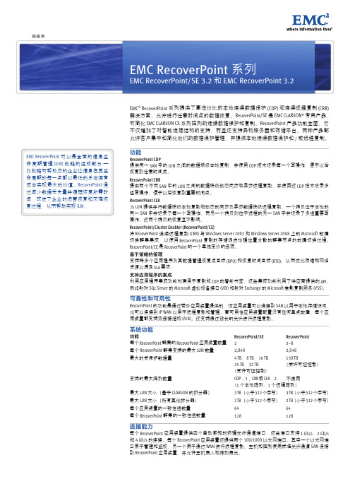
可靠性和可用性
RecoverPoint 的功能是通过带外应用装置提供的,该应用装置可以连接到 SAN 以用于本地存储访问, 也可以连接到 IP WAN 以用于远程复制和管理。高可用性应用装置配置没有任何单点故障,每个应 用装置都支持双连接结构 (A/B)。还支持通过延长的光纤进行远程复制。
系统功能
功能 每个 RecoverPoint 群集的 RecoverPoint 应用装置数量 每个 RecoverPoint 群集支持的最大 LUN 数量 最大的受保护数据量
RecoverPoint CLR 为 LUN 提供并行数据块级本地复制和动态的同步及异步数据块级远程复制,一个拷贝位于本地的 同一 SAN 中并记录了每一个写操作,而另一个拷贝则位于远程的另一 SAN 中并记录了多组重要写 操作。这两个拷贝的恢复互不影响。
RecoverPoint/Cluster Enabler (RecoverPoint/CE) 将 RecoverPoint 连续远程复制 (CRR) 与 Windows Server 2003 和 Windows Server 2008 上的 Microsoft 故障 切换群集集成,以使用 RecoverPoint 复制的存储促进地理位置分散的群集节点的故障切换过程。 RecoverPoint/CE 是 RecoverPoint 的一个单独定价的选项。
EMC2、EMC、CLARiiON、Connectrix、PowerPath、UltraFlex、UltraScale 和 where information lives 是 EMC Corporation 在美国和其他国家 / 地区的注册商标或商标。VMware 是 VMware, Inc. 的注册商标。本文提到的 所有其他商标分别是其各自所有者的财产。© 版权所有 2007、2009 EMC Corporation。保留所有权利。中国印刷。07/09 规格表 H2770.8
EMC Training.ppt

EMC
EMC标准及其测试
• 标准的分类
product standard
product family standard
generic standart
Basic standard
按层次分
IEC61000系列
EMC
EMC标准及其测试
EMI测试 ✓辐射骚扰电磁场(RE) ✓骚扰功率(DP) ✓传导骚扰(CE) ✓谐波电流(Harmonic) ✓电压波动及闪烁(Flicker) • 瞬态骚扰电压(TDV)
• 骚扰功率测试原理图
EUT
Power Probe
AE
EMI Receiver
EMC
EMC标准及其测试
• 传导发射:连续干扰电压、电流测量(CE)
– 电压法:交、直流电源线、天馈线、信号线(dBµV) – 电流法:信号线( dBµA) 电压限值例:
EMC
EMC标准及其测试
• 电源线骚扰电压测试原理框图
– 切断电磁干扰通过空间转播的途径,衡量指标为屏 效能。
• 滤波
– 在频域上处理电磁噪声的一种技术,其特点是将不 需要的一部分频谱滤掉。
• 接地
– 提供有用信号或无用信号,电磁噪声的公共通路, 有效设计地平面,可以抑制电磁噪声。
• PCB设计
EMC
电磁兼容基本概念
• 电磁兼容设计成本评估方法
设计方法
EMC
EMC标准及其测试
EMC标准
• 国际电工委员会IEC有以下分会进行EMC 标准研究
– CISPR:国际无线电干扰特别委员会 – TC77:电气设备(包括电网)内电磁兼容技术委员
会
– TC65:工业过程测量和控制技术委员会
EMC
MEDTRON用户指南列表说明书
USER GUIDE LISTINGMSI Contact ListNOTE: See Other Resources on Page 2APPOINTMENT SCHEDULINGAppointment SchedulingSetup/Maintain Master Appointment Scheduler Verification of Benefits/Precerts BASIC CONCEPTSHelp TextKeyboard StandardsOperational Assistant/Commands Standard Function Keys & Options BATCH ENTRYAnesthesia Charge Entry Batch Charge EntryBatch Charge Entry Reverse Rekey Charge Function Bulk Payment Entry Discrepancy Report HPSA PaymentsNSF/Stop Payment/Stale Checks Payment Posting Tips Regular Payment EntrySNF/Home Health/Hospice Billing – Medicare & LA Medicaid System Charge Balance AdjustmentTo Work Credit Open Items and Unapplied Pymt-Adj CLOSING & SPECIAL FUNCTIONSArchive Account InstructionsF10 Restricted Commands Work With Objects Locks(Contact Software Support ) F10 Special CommandsiSeries Initialize Tape-Entire System Backup MSI iSeries EOD/EOM/EOY Closing To Create a Condition/Rule COLLECTION TASK MODULECollection/Task Module ELECTRONIC CLAIMSEMC ERA Carrier Parameters EMC Errors/Electronic Claims ListEmdeon Vision for Claim ManagementERA Receive/Prepare/Create Unprocessed Batch Download ERA 835 File via PaySpan MREP Split ERATo Complete EDI (EMC, ERA & EFT) Setup for BCBS LA, LA Medicare, LA Medicaid & Clearinghouse To Reset LA Medicare EMC/ERA Access FRONT DESKCo-Pay Feature Front DeskFront Desk Charge Ticket List F15 Authorization RecordInsurance Card – Drivers License Scanning Instructions List Incomplete Masters (Orphaned Insurance Card Scans) ReportOB Billing GridUnproc/Proc List Transactions Reports Vaccines & Administration HISTORY & DEMOGRAPHICSAdd/Change/Delete Insurance Information Patient HistoryINDUSTRIAL MEDICINE MODULEIndustrial Medicine INSURANCE/LABELSGenerate LabelsMedicare Policy # / MBIMedicare – Replacement/Advantage (MCRR) Products IdentificationSelected Insurance Re-files: Adjustments and Void Claims System Deletion of Claims Outstanding 0-Cr Bal Chgs System Refiles/Generate Insurance EMC Preparation AndSubmittalTo Work “Secondary Claims Held Over ## Days” ReportInstructionsMEDEHR/MEDSUITESee MEDEHR Resources section of the MEDTRON website(https:///).MEDICAID GUIDESLA Medicaid Community Care Monthly Capitation Fee (CAP) LA Medicaid Community Care Referral Exempt LA Medicaid Community Care VA MedallionMISC TRAININGAccounts Receivable Analysis ToolsAdvance Beneficiary Notice (ABN) and Medical Necessity (MN) Audit LogAvoid Low CollectionsClaim Information Reference Number CMS Web Based Training CoursesEnable User Sign-on (Contact Software Support ) External EHR Interface with MPMS Global GuidelinesHow To Setup A Join Me SessionInstalling Insurance Card Scanning Software Ver 3-1 Inscards 3.1 Interface/Download Programs PQRS PrefaceTo Add-Delete Users to-from iSeries – iSeries Clients Only(Contact Software Support )To Add Transfer Data Function for Office 2007 iSeries Access forWindowsTo Change MEDPM (iSeries) Default Color Scheme To Clear Cache in Firefox BrowserTo Convert iSeries Reports using the iSeries Navigator To Create an Excel Spreadsheet From iSeries Data (SQLCommand)To Obtain Tax or Employer ID Numbers and CP575 Letters PATIENT INFORMATIONAccount Status Codes Combine Patient Accounts Online Eligibility RequestsPatient Demographics Add & Change Search and Scan OptionsSystem Transfer To Patient Responsibility Workers’ Comp Accounts and Claims RECOMMENDATIONSComments (Common Abbreviations) REPORTSBell Curve ReportsCharge Application Report EDC ReportList/Delete Unused Insurance Codes List Patients W/ Specific InsuranceRelative Value Units (RVU) Productivity Report Reports OverviewReports For Work Prior To EOM Close Transaction History Report SETUP & SUPPORTCMS 1500/ANSI Field Completion Situational Field Comments Collector CodesDMERC Claims SetupInsurance (Claim) Directives: Electronic & Split/Break to New Claim Medical NecessityNational Correct Coding Initiative (NCCI) NPI Registry Search Search FeatureSetup/Maintain ERA Comments/Messages Setup/Maintain Insurance Company Master Setup/Maintain Letters/Labels Setup/Maintain Location MasterSetup/Maintain Referral Source Master Setup/Maintain Setup & Support Files Setup/Maintain Specific Action Master Setup/Maintain Transaction Master Setup Online EligibilityTo Obtain/Edit a National Provider Identifier (NPI) TPL UpdatesSTATEMENT/LETTERSGenerate Letters StatementsFinance-Statement ChargesTo Print Patient Demographics for Labcorp Order FormVFC Medicaid ImmunizationsThe above User Guides are linked to the most current published version. All User Guides are updated as new information is made available and therefore may be in the process of being revised. Check back often to ensure most recent version is being used. If a User Guide presents in black with no link, this User Guide is in the process of being created.If a User Guide presents in black, the guide is in the process of being updated/revised, please contact Support Dept via email: or phone (985) 234-0599 to request us to expedite its completion.A User ID and Password are required to access all of the User Guides. If the further assistance or a User ID and password is needed, please contact our Support Dept via email: or phone (985) 234-0599.MEDTRON Software Intelligence – All rights reserved.OTHER RESOURCES MSI Contact List USER FORMS:MDS-MSI Client User Access Agreement - Security PolicyMDS/MSI Menu OptionsE&M RESOURCES:E&M Information PacketMEDICARE RESOURCES:CMS RVU and Payment Policy IndicatorsCMS RVU List (per CMS Website)PRACTICE FORMS:Demographics Intake Form – Web versionDemographics Intake Form – iSeries versionOTHER RESOURCES:Acronym List/Glossary of Healthcare TermsCarrier Precertification/Prior Authorization (PA) ListingCMS Medicare Fraud & Abuse – Prevention, Detection, and Reporting Fact Sheet (False Claims Act)MSI 2018 CPT-HCPCS Code Resource GridMSI ICD-10-CM Code Resource GridLCD/Medical Policy ListingsTherapy Billing GridModifier Staff Training Presentation。
ARTISAN TECHNOLOGY GROUP 商业用品说明书

Programmable Safety SystemsPSS-RangePSS 3056 SeriesInstallation ManualItem No. 19 025All rights to this manual are reserved by Pilz GmbH & Co. KG. Copies may be made for internal purposes.In the interests of continual technical advancement we reserve the right to amend specifications without prior notice. No responsibility accepted for errors or omissions.The names of products, goods and technologies used in this manual are trademarks of the companies concerned.VII, 01/00ContentsContentsIntroductionIntroductionSafety RegulationsSafety RegulationsSafety Regulations• Ensure there is sufficient ventilation to prevent heat building up within thecontrol cabinet.•In extreme ambient conditions, additional measures may be required inorder to keep within the prescribed value range (e.g. air-conditioningwithin the control cabinet).•The safety system must be installed in such a way that buttons andswitches cannot be operated unintentionally.Connections•Cable layout must meet the EMC-guidelines stated in Chapter 3.•Each supply terminal should have its own power supply cable as shownin the connection diagrams (do not make through-connections).•All supply terminals must be supplied with the voltages they require,otherwise it will not be possible to carry out the module test (errormessage will be generated).•The current at each slot connector should be 10 A maximum.•Screened cables are not required for digital I/Os.• Minimum ranges for cable cross sections on field connection terminalsin mm2, in accordance with EN 61 131-2, 08/94:- Digital inputs: 0.5 (AWG20) ... 1.5 (AWG16)- Digital outputs: 0.5 (AWG20) ... 2.0 (AWG14)- Power supply: 1.5 (AWG16) ... 2.5 (AWG12)- Earth: 1.5 (AWG16) ... 2.5 (AWG12)•Use copper wiring.•The torque setting on the connection terminals should be 0.5 ... 0.6 Nm.Safety RegulationsOverviewThe safety system is designed to be installed within an electromagneticindustrial environment. To ensure electromagnetic compatibility thecorrect procedures must be carried out when installing the system.A device is electromagnetically compatible if:•It functions without error in a given electromagnetic environment.•It does not adversely affect its own environment.Electromagnetic interference reaches the system through:•Radiated fields•Power supply•Earth cabling•Bus•Interfaces•Input and output cablesThe interference can be transferred from the source to the receiver(interference sink) via the coupling routes.Interference reaches the interference sink (e.g. the PSS 3056) in variousways:•DC couplingThis occurs if the source and sink of interference have common cableconnections. The common cable presents complex resistances, inducingpotential differences. Possible sources of interference are switches/relays, running motors or varying potentials for other systems on thesame power supply.Fig. 3-1: Electromagnetic interferenceElectromagnetic Compatibility (EMC)Coupling Interference sinkSource of interferenceElectromagnetic Compatibility (EMC)•The housing should be connected to the earth conductor “PE”. A cablecross section of at least 2.5 mm2 should be used. Connections shouldbe kept as short as possible.•Always connect the earth conductor “PE” to the central earth point in starform.•The 0 V connections on all the 24 V power supplies should be connectedand the 0 V mains earthed at a single point. The connection of the 0 Vsupply to the central earth bar or earth fault monitor must be inaccordance with the relevant national regulations (such as EN 60 204,VDE 0113, NFPA 79-1991:17-7, NEC: Article 250, for example).•Connections should be protected from corrosion.•Flexible earthing straps should be used on moving earth parts (e.g.machine parts, gates). Ensure these earthing straps are as short andwide as possible.CablingIt is possible to differentiate between cables according to their function.The following groups exist:•Group 1: Data and supply lines for DC voltages below 60 V and ACvoltages below 25 V•Group 2: Data and supply lines for DC voltages from 60 V to 400 V andAC voltages from 25 V to 400 V•Group 3: Supply lines above 400 VCabling inside buildings:•The cable groups listed above should be laid separately.•Cables of the same group can be laid within the same cable duct.•Lines from group 1 and group 2 should be laid in separate groups or incable ducts which are at least 10 cm apart.•Lines from group 1 and group 3 should be laid in separate groups or incable ducts which are at least 50 cm apart.Electromagnetic Compatibility (EMC)•Data and signal lines should be laid as close as possible to an earthedsurface.Cabling to open air systems:•As far as possible use metal conduits. These should be electricallyconnected and earthed.•Ensure there is sufficient protection against lightning by:-Using metal conduits earthed at both ends, or concrete cable ducts withreinforcements connected across the joints.Equipotential bondingPotential differences can occur through potential connected couplingsbetween the safety system and peripheral devices or cable shields, whichare connected at either end and have different earth connections. In orderto avoid interference, equipotential bonding cables must be installed. Indoing so, you must ensure the following:•Select a low impedance equipotential bonding cable.•If the safety system and peripheral devices are connected with screenedsignal cables which are earthed at either end, the impedance iscalculated as follows:Impedance equipotential bonding cable = 10% of screen impedance.•Select the following as standard values for the cross section of theequipotential bonding cable:16 mm2 for equipotential bonding cables up to 200 m in length.25 mm2 for equipotential bonding cables over 200 m in length.•Use copper or galvanised steel equipotential bonding cable.•Connect equipotential bonding cables to the earth conductor over aswide a surface area as possible.•As short a distance as possible should be kept between the equipotentialbonding cable and signal cable.Screened cablesInterference currents arising from electrical, magnetic or electromagneticfields of interference must be diverted to cable screens via the earth barsconnected to the enclosure. Please remember the following:•Connect the screens with low impedence to the earth conductor.•Use cables with braided screening, with a minimum cover area of 80%.•For high frequency areas connect the screen at both ends.•For low frequency areas connect the screen at one end; this is also validwhen laying cables without equipotential bonding or using foil screens.•Use metal or metallised plugs to connect cables for serial data transfer.•The screen must have no connection to the connector housing if it is notlocated at the end of the cable.•At the point where the cable enters the cabinet, connect the screen tothe earth bar, without making a break in the cable. Use metal cableclamps which cover the screen over a wide surface area.Take the screen as far as the module, but do not lay it on top of themoduleSuppression of inductive loadsSuppression should not be used to protect the semiconductor outputs. Insulation voltage testThe PSS systems from the PSS 3056 series are connected to thefunctional earth through protective elements on the supply voltage.Insulation voltage tests can only be carried out with voltages up toapproximately 42 V.Electromagnetic Compatibility (EMC)Testing the EMC-compatibility of an installationUse the following list to check that the safety system has been installed toconform with EMC-regulations.Check Action DoneBefore installation:Are there areas with a high Make detailed plans for EMCprobability of interference?protection in these areas.(e.g. computers running,process control areas,distribution cabinets, cablecasing, frequency converters,hand-held radios etc.)Are areas where computers If necessary shield the wholeare running and areas such area.as process control roomssufficiently shielded fromelectromagnetic coupling?Have you, or the installer,Some important points: Laysufficient knowledge where cables close to earth, keep clearcable layout is concerned?of other electrical equipment,keep cables in ducts separatefrom other parts of theinstallation, keep cables as shortas possible.Is the supply voltage free Build in a mains filter whereof interference?interference may occur.EMC characteristics of Test under operating conditions,individual units / all e.g. while hand-held radios are inunits once installed?use, or HF frequency generatorsare close by. Test static dischargewith operating personnel, testmutual interference betweenunits under different operatingconditions.Electromagnetic Compatibility (EMC)Check Action DoneDuring installation:Earthed parts connected Most important are thecorrectly?connections to base moduleracks, racking bars, earthconductors and earth bars.Inactive metal parts should beconnected over a wide surfacearea and earthed to a central point.With insulated metal: Removeinsulation or use specialcontact fixings. Protect theconnection from corrosion. Connectthe cabinet doors to the body ofthe cabinet using earthing straps.Are the cables laid Separate cables into groups.correctly?Supply and signal leadsmust be laid separately.Are the shields connected Use shielded cables for analoguecorrectly?and data leads.Use metallic plugs.Connect cable shields to earth barat point of entry to cabinet.Connect cable shields over a widesurface area and with lowimpedance.Equipotential bonding Equipotential bonding cablescarried out?should be laid if the installationextends over a wide area.Are inductive loads Inductive loads not switched byswitched?the PSS 3056 must be wiredwith suppression elements.24 VDC power supply?The power supply must conform toDIN VDE 0551 / EN 60 742 andDIN VDE 0160.InstallationPG FS RUNSTOPST AUTO PGSPS F-Stack RS 232InstallationConnecting the Inputs and OutputsConnecting the Inputs and OutputsConnecting the Inputs and OutputsFig. 5-4: Terminal configuration on the PSS SB 3056 (identical to the standard PSS 3056)Notes on wiringWhere safety-relevant applications are concerned, it is essential thatshort circuits and line breaks are unable to cause a hazardous conditionwithin a plant.The way in which this is done will depend on the degree of hazard withinthe plant itself, the switching frequency of the input devices and the levelof safety of the input devices and actuators. These points must beassessed in conjunction with the relevant standards or approvals body(e.g. BG or TÜV).The following terms are important:•Test pulsesThese are signals which change status on several occasions within aperiod of time.•Single-channel safe input devicesThese are positively-driven normally-closed contacts which open onactuation (failsafe principle).•Elimination of short circuits between signalsThis is possible within electrically-enclosed areas and also outsideelectrically-enclosed areas for signals conducted in different multicorecables. However, all components must meet the relevant regulations inaccordance with EN, DIN and VDE.•In principle, the possibility of earth faults and line breaks occurringcannot be eliminated.If a dual-pole switching output on the PSS is used to drive the actuators, atest for short circuits and line breaks will automatically be carried outduring each cycle. For this purpose the actuator will be switched off forapproximately 100 µs. When using single-pole outputs or test pulses, aswitch-off test will only be carried out if designed into the self-check.With multi-channel pulsed input devices, short circuits and line breaks canbe detected via feasibility checks in the control program.The input test on the programmable safety system uses test pulses toenable the system's operating program to carry out a test to detect shortcircuits and line breaks. The following pages contain details of connectionexamples which may be of use when wiring the unit.Connecting the Inputs and OutputsConnecting the Inputs and OutputsConnecting the Inputs and OutputsConnecting the Inputs and OutputsConnecting the Inputs and OutputsExample: Dual-channel, failsafe input device, with test pulseFeatures:•This type of connection is mainly used for signal inputs with infrequentoperation.• The operating system will detect all shorts between contacts and shortcircuits to L+ and L-.• Short circuits across the contact can be detected via the feasibility checkin the application program.•The test pulse must be allocated to the input via the configurator on theprogramming device.•Only input devices with N/C contacts can be tested (in the case of diver-se channels, only the N/C contact).•On input devices with identical channels, each channel should be givena separate signal, where possible. This will ensure that all short circuitsare detected, with the exception of short circuits which short out theinput device (cable from the signal to the input device and cable from theinput device to the input).•If the input device has only one signal, a short circuit between thecables from the input device to the inputs will not be detected. Youshould always ensure that the unit is suitably wired to avoid the risk ofthis type of short circuit.•Cable runs:-200 m-With 1 kOhm resistance parallel to input: max. 800 mConnecting the Inputs and OutputsConnecting the Inputs and OutputsConnecting the Inputs and OutputsInterfacesInterfacesAppendixChanges to the Installation ManualChanges from version IV to version VThe Installation Manual was completely revised and is now also valid forthe PSS SB 3056.The most significant changes are as follows:•Chapter entitled "Safety Regulations" was restructured and the contentscorrected.•Page 3-3, description of how to earth the 0 V supply was added.•Page 3-3, section entitled "Cabling" was amended.•Page 3-5, section entitled "Suppression of inductive loads" wasamended.•Page 5-1 to 5-4, connector descriptions for the PSS terminal blocks wasadded.•Chapter 5 was completely revised.•Chapter 6 was added to include a description of the interfaceconfigurations.Changes from version V to version VIPage 3-5, section entitled "Insulation voltage test" was added.Changes from version V to version VI•Page 2-4, Condensation is not permitted.•Page 2-5, the use of wiring which can withstand insulation temperaturesof 75° C is no longer specified.AppendixAUSB LBRDTRDKEFFINGBISEIRL...wwwPRCROKAJMEXNZPNLUSACHIn many countries we arerepresented by sales partners.Please refer to our Homepage for further details or contact our headquarters.Pilz GmbH & Co. KG Sichere Automation Felix-Wankel-Straße 273760 Ostfildern, Germany Pilz Ges.m.b.H.Modecenterstraße 141030 Wien AustriaTelephone:01 7986263-0Telefax:01 7986264E-Mail:************Pilz AustraliaIndustrial Automation LP .9/475 Blackburn RoadMt. Waverley, Melbourne VIC 3149AustraliaTelephone:03 95446300Telefax:03 95446311E-Mail:***************.auPilz BelgiumBijenstraat 49051 Gent (Sint-Denijs-Westrem)BelgiumTelephone:09 3217570Telefax:09 3217571E-Mail:************Pilz do Brasil Sistemas EletrônicosIndustriais Ltda.Rua Ártico, 123 - Jd. do Mar 09726-300São Bernardo do Campo - SP BrazilTelephone:11 4337-1241Telefax:11 4337-1242E-Mail:***************.brPilz lndustrieelektronik GmbHGewerbepark Hintermättli Postfach 65506 Mägenwil SwitzerlandTelephone:062 88979-30Telefax:062 88979-40E-Mail:************Pilz GmbH & Co. KGSichere Automation Felix-Wankel-Straße 273760 Ostfildern GermanyTelephone:0711 3409-0Telefax:0711 3409-133E-Mail:*****************Pilz Skandinavien K/SEllegaardvej 25 L 6400 Sonderborg DenmarkTelephone:74436332Telefax:74436342E-Mail:************Pilz lndustrieelektronik S.L.Camí Ral, 130Polígono Industrial Palou Nord 08400 Granollers SpainTelephone:938497433Telefax:938497544E-Mail:************Pilz France Electronic1, rue Jacob Mayer BP 1267037 Strasbourg Cedex FranceTelephone:03 88104000Telefax:03 88108000E-Mail:********************Pilz Skandinavien K/SPakilantie 6100660 Helsinki FinlandTelephone:09 27093700Telefax:09 27093709E-Mail:***************Pilz Automation TechnologyWillow House, Medlicott Close Oakley Hay Business Park CorbyNorthants NN18 9NF United KingdomTelephone:01536 460766Telefax:01536 460866E-Mail:*************.ukPilz ltalia SrlVia Meda 2/A22060 Novedrate (CO)ItalyTelephone:031 789511Telefax:031 789555E-Mail:************Pilz Ireland Industrial AutomationCork Business and Technology Park Model Farm Road Cork IrelandTelephone:021 *******Telefax:021 *******E-Mail:*************Pilz Japan Co., Ltd.Shin-Yokohama Fujika Building 5F 2-5-9 Shin-Yokohama Kohoku-kuYokohama 222-0033JapanTelephone:045 471-2281Telefax:045 471-2283E-Mail:************.jpPilz de Mexico, S. de R.L. de C.V.Circuito Pintores # 170Cd. Satelite C.P . 53100Naucalpan de Juarez, Edo. de Mexico MexicoTelephone:55 5572 1300Telefax:55 5572 4194E-Mail:************.comPilz NederlandPostbus 1864130 ED Vianen NetherlandsTelephone:0347 320477Telefax:0347 320485E-Mail:************Pilz New Zealand3 Kohanga Road Managere Bridge Auckland New ZealandTelephone:09-6345350Telefax:09-6345350E-Mail:*******************.nzPilz Industrieelektronik S.L.R. Eng Duarte Pacheco, 1204 Andar Sala 214470-174 Maia PortugalTelephone:229407594Telefax:229407595E-Mail:************Pilz China Representative OfficeRm. 302No. 88 Chang Shu Road Shanghai 200040ChinaTelephone:***********Telefax:***********E-Mail:**************.cn Pilz Korea Office402 Samsung Midas Officetel 775-1, Janghang-Dong,Ilsan-Gu, Koyang-Si Kyungki-Do 411-837KoreaTelephone:031 8159541Telefax:031 8159542E-Mail:*****************.krPilz Skandinavien K/SEnergigatan 10 B 43437 Kungsbacka SwedenTelephone:0300 13990Telefax:0300 30740E-Mail:***************Pilz Elektronik Güvenlik Ürünlerive Hizmetleri Tic. Ltd. †ti.Tan i‡ MerkeziKükürtlü Caddesi No: 67C-Blok Daire: 116080 Bursa TurkeyTelephone:***********Telefax:***********E-Mail:***************Pilz Automation Safety L.P .7150 Commerce Boulevard CantonMichigan 48187USATelephone:734 354-0272Telefax:734 354-3355E-Mail:****************3/04 P r i n t e d i n G e r m a n y。
搜集EMC磁阵日志方法
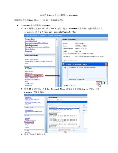
如何收集Block上的诊断日志 - SP collects
请确认您的阵列Flare版本,31和32的界面略有差别
•在Flare31中如何收集SP collects
1.在IE地址栏里输入SPA或者SPB IP地址,进入Unisphere管理界面,选择该阵列并点
击System,选择SPA Tasks bar – Generate Diagnostic Files:
2.等待10分钟左右,点击Get Diagnostic Files,选择最新生成的data.zip文件。
点击
transfer,传输至本地:
3.用相同的方法收集B端。
•Flare版本32,则参考以下步骤
1.在IE地址栏里输入SPA或者SPB IP地址,进入Unisphere管理界面,选择该阵列并点击
System:
2.在Diagnostic Files选项中,选择“generate Diagnostic Files - SPA”,出现Confirm窗口点击
“Yes”,Success窗口点击“OK”
3.同样选择“Generate Diagnostic Files - SPB”,在出现的对话框里选择“Yes”- “OK”.
4.选择“Get Diagnostic Files - SPA”,在出现的窗口中选择刚才产生的data.zip文件。
格式为
SN_SPA_Todaydate_data.zip。
如果发现文件结尾格式为runlong.txt,则需要继续等待。
等变成SN_SPA_Todaydate_data.zip各位的文件名后,选中该文件,选择保存路径,点击“Transfer”
5.重复以上步骤,将B边的日志传输到本地即可。
Advanced Test Solutions EMC 测试手册:涌动耦合网络 CDN 3083-S
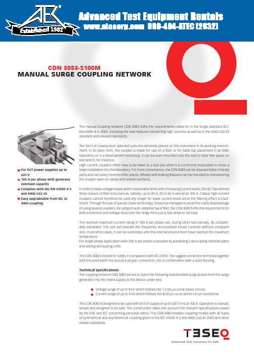
A d v a n c e d Te s t S o l u t i o n s f o r E M CMANUAL SURGE COUPLING NETWORK CDN 3083-S100MFor EUT power supplies up to 620 V 100 A per phase with generous overload capacity Complies with IEC/EN 61000-4-5 and ANSI C62.45 Easy upgradeable from IEC to ANSI couplingThe manual coupling network CDN 3083 fulfi ls the requirements called for in the Surge standard IEC/EN 61000-4-5: 2005, including the new features concerning high currents as well as in the ANSI C62.45 standard and relevant standards.The form of construction selected suits the demands placed on the instrument in its working environ-ment. In its basic form, the coupler is made for use on a fl oor or for table top placement in an EMC laboratory or in a development workshop. It can be even mounted onto the wall to have free space on test bench, for instance.High-current couplers often have to be taken to a test site when it is commonly impossible to move a large installation into the laboratory. For more convenience, the CDN 3083 can be disassembled in handy parts and can easily move to other places. Wheels with braking features can be mounted to manoeuvring the coupler even on ramps and uneven surfaces.In order to keep voltage losses within reasonable limits with increasing current levels, the IEC has defi ned three classes of fi lter inductances, namely: up to 20 A, 20 to 60 A and 60 to 100 A. Classic high-current couplers cannot therefore be used any longer for lower current levels since the fi ltering effect is insuf-fi cient. Through the use of special choke technology, Teseq has managed to avoid the costly disadvantage of using several couplers. By using an auto-adaptive back fi lter, the CDN 3083 fulfi ls the requirements for both protection and voltage drop over the range from just a few amps to full load.The nominal maximum current rating of 100 A per phase can, during short test periods, be consider-ably exceeded. The unit will tolerate the frequently encountered inrush currents without complaint and, in extreme cases, it can be overstress until the internal environment have reached the maximum temperature.For single phase application even 200 A per phase is possible by paralleling 2 decoupling network paths and adding decoupling units.The CDN 3083 is tested for safety in compliance with IEC 61010. The rugged connection terminals together with the solid earth line assure a proper connection, this in combination with a solid housing. Technical specifi cationsThe coupling network CND 3083 serves to inject the following standardized surge pulses from the surge generator into the mains supply to the device under test:Voltage surge of up to 8 kV which follows the 1.2/50 µs curve (open-circuit)Current surge of up to 4 kA which follows the 8/20 µs curve (short circuit conditions)The CDN 3083 is designed to be used with an EUT supply of up to 620 V rms at 100 A. Operation is manual, simple and designed to be safe. The construction takes into account the relevant specifi cations issued by the VDE and IEC concerning personal safety. The CDN 3083 enables coupling modes with all types of symmetrical and asymmetrical coupling given in the IEC 61000-4-5 and ANSI C62.41 2002 and other related standards. 1981A d v a n c e d Te s t S o l u t i o n s f o r E M C MANUAL SURGE COUPLING NETWORK CDN 3083-S100MTeseq AGNordstrasse 11F 4542 Luterbach SwitzerlandT + 41 32 681 40 40 F + 41 32 681 40 48***************691 – 157A May 2008The CDN 3083-S100 set: 1 x Surge decoupling network CDN 3083-S100 N – L1 1 x Surge decoupling network CDN 3083-S100 L2 – L3 2 x Earth rail 1 x Allen key isolated 1 x User Manual CDN 3083 E 1 x Test certifi cate 1 x Wheel set 2 x Connection tables, laminated IEC coupling set 1 x INA 3080 Surge coupling unit ANSI coupling set/optional IEC coupling 2 x INA 3080 Surge coupling unit 1 x Connection cable Depending on generator used, following complementary items are in the set:NSG 2050 generator system 1 x INA 3085 Synchronisation unit for NSG 2050 system 2 x Cable 1 m, with Fischer/Lemo connectors 1 x Dummy plug for NSG 2050 generator NSG 3040 and Modula 1 x INA 3084 Synchronisation unit for NSG 3040 family2 x Cable 1 m, with each a Fischer/Fischer connectors。
- 1、下载文档前请自行甄别文档内容的完整性,平台不提供额外的编辑、内容补充、找答案等附加服务。
- 2、"仅部分预览"的文档,不可在线预览部分如存在完整性等问题,可反馈申请退款(可完整预览的文档不适用该条件!)。
- 3、如文档侵犯您的权益,请联系客服反馈,我们会尽快为您处理(人工客服工作时间:9:00-18:30)。
11
Networker---竞争分析
Symantec Veritas 面向企业客户的 NetBackup 面向商业客户的 BackupExec CommVault Simpana 主要面向商业客户, 但正在向大企业客户拓展
整体解决方案; Networker Fast Start 配置简单
重复数据消除和整体解决方案
© Copyright 2010 EMC Corporation. All rights reserved.
8
Networker---方案配置需求
您有多少台服务器需要做备份? 您有多少个应用程序,X86平台多少?UNIX平台多少?虚拟化平台多少? 您现在有备份设备吗?磁盘、磁带还是其他设备? 您的备份数据需要保留多长时间? 您备份窗口时间是? 您有哪些应用程序需要进行LAN-Free备份? 您需要做备份恢复测试平台吗? 您是否NAS存储系统需要数据备份?
4
EMC BRS新一代备份产品线
备份/恢复体系结构
应用程序备份 客户端
备份/介质 管理器
现场备份 存储
灾难恢复 存储
磁带
传统(以磁带为中心)
磁带
EDL NetWorker
VTL/磁带
Data Domain
转型(以磁盘为中心)
虚拟机
Avamar
现场
异地
DPA (Data Protection Advisor)数据保护顾问管理软件
– – – – 低于标准定价至多 50% 低于 CommVault 至多 30% 便于合作伙伴和销售代表进行配置和订购 点击次数较 CommVault 最多减少 80%
• 一个型号,便于订购 • 使用安装向导一天便可完成安装
Fast Start 包括:
• NetWorker Server(Windows 或 Linux) • 二十个客户端 • 多达 5 个应用程序模块 - 从 Exchange、 SQL Server 和 Oracle 中选择 • 10TB 磁盘备份容量或 DL • 40 个插槽的磁带库 • NetWorker 基于视频的培训
缩短恢复时间可实现连续业务运营 延长恢复时间或数据丢失将转化为业务恢复
(RPO) (RTO)
5
早晨
6
早晨
7
早晨
8
早晨
9
上午
10
上午
11
上午
12
中午
1
下午
2
下午
3
下午
4
下午
5
下午
6
下午
7
晚上
宣布发生 灾难 上午 10 点
© Copyright 2010 EMC Corporation. All rights reserved.
使用 NetBackup 的企业客户和使用 BackupExec 的商业客户均占有较重的 市场份额
CommVault Simpana 在商业领域增长最 快
IBM Tivoli Storage Manager
在 IBM 客户中很有影响
© Copyright 2010 EMC Corporation. All rights reserved.
EMC Products and Solutions training for Partners
BRS and RecoverPoint
王威 13913000605
© Copyright 2010 EMC Corporation. All rights reserved.
1
Agenda
• EMC 备份产品及解决方案介绍
• 独立节点冗余阵列 (RAIN) 体系结构
– 内部磁盘存储和 CPU – 提供了高可用性和跨节 点的容错功能
Avamar 服务器
跨存储节点的 循环奇偶校验 经验证的检查 点
• 网格体系结构允许在线 扩展并提高了性能 • 每日完整性检查 • 针对磁盘故障的 RAID 保护
© Copyright 2010 EMC Corporation. All rights reserved.
20
使用案例/成功案例 备份 VMware 基础架构
业务难题
– 虚拟机带来了巨大的好处... – ... 但是传统的备份软件跟不上这一步伐
– 在同样的硬件和资源上,数据和文件的总数量更多 了 – 更长的相互重叠、并发的备份窗口
益处
– Avamar 减轻了虚拟机备份负担
– 要移动的数据最多可减少 95% – 备份时间最多减少 90% – NIC、CPU 和内存使用量大幅减少
Avamar VM 操作系统
应用程序 操作系统
Avamar VM 操作系统
ESX 服务器 硬件
CPU
内存
NIC
磁盘
18
EMC Avamar 体系结构
大型远程站点
Avamar 软件代理
较小的远程站点
主要系统 Avamar Data Store
(加密) (加密)
Avamar Agent 仅 安装在主要系统上
– 支持通过 VM 来宾操作系统、ESX 服务控制台或 VCB 代理服务 器进行备份
“Avamar 可为多个虚拟机的备份节约可观的 时间和成本。 通过 Avamar,我们可以集中管理所有备份, 并且还能够快速恢复数据,直至文件级别。”
— Curtis Damhof,St. Peter’s Health Care Services 网络经理
– 源位置重复数据消除 – 可扩展的网格体系结构 – 灵活的物理和虚拟部署选项
• 最佳使用案例
– 远程办公室后勤办公室 (ROBO) – VMware – 大型 LAN 文件系统
© Copyright 2010 EMC Corporation. All rights reserved.
13
EMC Avamar 产品特点
© Copyright 2010 EMC Corporation. All rights reserved.
9
Networker---FAST Start
面向中型企业客户的完整版 NetWorker
• 一个解决方案 – Fast Start 是 NetWorker 的完整版 • 单一低价位让客户更容易承受
© Copyright 2010 EMC Corporation. All rights reserved.
5
Networker---主要优势
统一备份软件
集中化管理 业界领先的重复数据消除 高级应用程序支持 丰富的磁盘备份功能 覆盖虚拟和物理环境 可靠的可恢复性
© Copyright 2010 EMC Corporation. All rights reserved.
Avamar VM 操作系统
ESX 服务器 硬件
CPU
内存
NIC
磁盘
部署在经鉴定的行业标准服务 器上
与单点支持完全集成的硬件/ 软件产品
单节点 Avamar 服务器作为虚 拟机运行
© Copyright 2010 EMC Corporation. All rights reserved.
16
EMC Avamar 体系结构
服务器,而不是过去的几小时。”
— Mike DePhillip,弗吉尼亚车管局
益处 Avamar 远程办公室/分支办公室备 份非常简单、安全而且易于管理
© Copyright 2010 EMC Corporation. All rights reserved.
21
使用案例/成功案例 远程办公室/分支办公室备份
业务难题 数据保护的“致命弱点”
• • •
弗吉尼亚州
美国有四百多万个远程办公室 远程办公室的数据以每年超过 50% 的增长率增长* “Avamar 使我们能够将管理支持需求减 少 80%,将备份窗口减少 90%,并且在几 远程站点的 IT 员工通常能力有限而且缺少培训 分钟内就可以恢复丢失的文件和出故障的
数据中心
WAN
远程恢复站点
主要系统 (加密) Avamar Data Store (加密)
主要系统
磁带 存储区 Avamar Data Store
© Copyright 2010 EMC Corporation. All rights reserved.
19
技术优势
• 重复文件数据过多
– 备份带宽不足 – 无法进行远程办公室备份
6
Networker---工作机制
LAN
备份服务器 应用系统 数据库系统 应用服务器A 应用服务器B 应用服务器C
Tape1
© Copyright 2010 EMC Corporation. All rights reserved.
7
Networker---销售机会
您有数据保护机制吗? 您对当前的数据保护操作和性能是否满意? 您现在使用哪些备份应用程序?是否在整个公司范围内采用此标准? 您现在的备份环境是怎样的? 您是否有长期保留磁带的要求? 您正在使用什么样的文件系统、应用程序、电子邮件和数据库?您是否正在使用服 务器虚拟化? 您是否考虑过备份重新设计项目? 您是否有站点、服务器或存储整合计划? 您的远程办公室是否碰到了数据保护难题? 您与当前备份应用程序的维护合同是否即将到期?
独立完整的软硬件一体 备份恢复解决方案 源端 重复数据删除 基于子文件(数据块) 可变长度子文件 全局去重 永远增量的全备份
一步恢复 智能切分 最大程度 去重 节省备份 链路带宽 最佳粒度 单一采购
© Copyright 2010 EMC Corporation. All rights reserved.
• 全局源位置重复数据消除
– 在备份前发现重复数据 – 只存储一次 – 减少带宽
