MID NP701 说明书10.8.20
明基i701JD说明书

选择输入信号源 ....................................27
菜单功能 .......................................38
关于屏显菜单 ........................................ 38 使用基本屏显菜单 ............................... 40
基本屏显菜单 - 已连接输入信号 ..........40 基本屏显菜单 - 未连接输入信号 ..........43
- 火警附近的地方。 - 环境温度超过 35°C/95°F 的地方。 - 海拔高于 2000 米 (6562 英尺)的地方。
3. 请勿垂直竖立投影仪,否则会导致投影仪倾 倒,造成伤害或导致投影仪受到损坏。
2000 米 (6562 英
尺)
0米 (0 英尺)
重要安全说明 3
5. 当投影仪打开时 (即使处于待机模式),请勿 9. 在使用过程中不要直视投影仪镜头。强光束可
指示灯...................................................... 63 故障排除 ................................................. 64 规格 .......................................................... 65
7. 请勿踩踏投影仪或在投影仪上面放置任何 物体。
松下MID变频器说明书
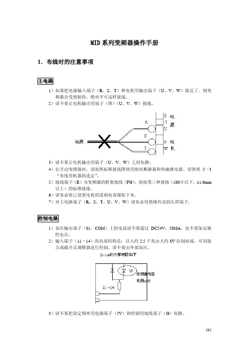
MID 系列变频器操作手册1.布线时的注意事项主电路1)如果把电源输入端子(R 、S 、T )和电机用输出端子(U 、V 、W )接反了,则变频器会受到损伤,绝对不可这样接线。
2)请不要让电机输出用端子(图)(U 、V 、W )接地。
3)请不要让电机输出用端子(U 、V 、W )之间短路。
4)在开动变频器时,请按照标准接线图使用熔丝断路器和热敏继电器。
请参照5—3“布线用机器的选定”。
5)地线端子(E )为变频器的框架地线(FG ),请按第三种接地(100Ω以下,¢1.6mm 以上)的标准接地。
6)请务必将已设置电机的进相电容器取下来。
7)对主电路端子(R 、S 、T 、U 、V 、W )请务必用绝缘外皮的压焊端子。
控制电路1)加在输出端子(01、COM )上的电流请不要超过DC24V 、50MA ,也不要加反极性电压。
2)输入端子(11—14)的内部结构是:以大约2.5千兆由大约8V 拉制而成,可用接点或敞开式调整器进行控制,请不要由外部加压。
3)请不要把设定频率用电源端子(5V )和控制用地线端子(G )短路。
285技成培训网 www .j c p e i x u n .c o m4)当用输出端子(01 COM)直接驱动继电器时,请插入续流二极管(FD)。
5)接在控制电路上的电线请用胶合线或屏蔽线。
ERA15-01ERB15-01请注意二极管的极性6)请把屏蔽线的屏蔽部分接地。
7)接在控制电路上的电线要与动力线分离。
8)关于电线的固定,要用螺丝刀垂直对准接线柱加以固定。
2 安全注意事项2-1 MID***W**的情况电源三相/单相单相AC100V50/60Hz单相输入的请接在R、T上正转/反转/286进行外部频率设定的情况* 电机在以最高频率运转,由于外部频率设定标度盘的位置,设定频率用电流接线端子(5V)和控制用地线端子(G)会短路。
因此,请务必把短路棒去掉之后再布线。
* 关于外部频率的设定,请将电位器面板向左旋转到最大限度后再进行。
道勤DC710说明书

701说明书V2.00
目录1装置概述 (1)1.1应用范围 (1)1.2保护配置 (1)1.3主要性能特点 (1)2技术参数 (3)2.1机械及环境参数 (3)2.2额定电气参数 (3)2.3主要技术指标 (3)2.4通讯接口 (4)2.5纵联保护通道说明 (4)3保护原理 (6)3.1起动元件 (6)3.2选相元件 (6)3.3可变特性工频变化量电抗距离继电器 (7)3.4纵联暂态方向保护(暂态电流方向继电器) (11)3.5纵联零序方向保护(零序方向继电器) (13)3.6距离继电器 (14)3.7零序电流保护 (18)3.8振荡闭锁 (18)3.9TV断线检测和紧急状态保护 (19)3.10合闸于故障保护 (20)3.11非全相运行 (21)3.12重合闸 (21)3.13跳闸逻辑和重合闸闭锁 (24)3.14纵联保护逻辑框图 (25)4辅助功能 (28)4.1信号系统 (28)4.2事故分析与过程记录 (28)5定值及整定说明 (34)5.1数值型定值 (34)5.2投退型定值 (35)5.3定值整定说明 (36)6硬件说明 (39)6.1装置整体结构(硬件原理图) (39)6.2动作出口 (39)6.3输入开关量 (41)6.4信号接点 (42)6.5装置接线与安装 (43)7订货须知 (44)7.1基本订货参数 (44)7.2装置软件编号及版本定义 (44)7.3装置型号列表 (44)附录A 装置使用 (45)A.1面板使用说明 (45)A.2菜单操作与显示 (46)附录B 装置调试与投运 (55)B.1调试资料准备 (55)B.2通电前检查 (55)B.3上电检查 (55)B.4整机调试 (55)B.5定值整定说明 (57)B.6装置投入运行操作步骤 (57)B.7注意事项 (57)附录C 保护装置通讯说明(IEC60870-5-103规约) (60)C.1物理接口 (60)C.2定值和交流量 (60)C.3保护动作事件 (62)C.4自检信息 (63)C.5保护开关量 (63)C.6故障录波实际通道序号表(ACC) (64)附录D 保护装置特殊版本说明 (65)D.1三相不一致保护 (65)D.2失灵起动 (65)D.3相关说明 (65)【附图1】装置端子排布置图(装置背视图) (67)【附图2】装置端子排接线图 (68)【附图3】装置正面布置及安装开孔图 (69)1装置概述1.1应用范围PRS-701超高压线路成套保护装置主要适用于500KV~110KV电压等级的高压线路,具有安全可靠、快速、灵敏、方便的特点。
JT701用户手册说明书
SKU: LOCK- 701
1
Content
Content................................................................................................................................. 2 1 Brief Description ...............................................................................................................4 2 Warranty Policy Statement ...............................................................................................4 3 Features List .....................................................................................................................5 4 Product basic parameters.................................................................................................5 5 Product Appearance .........................................................................................................6 6 Standard Accessories.......................................................................................................7 7 First Use............................................................................................................................8
MID说明书

目录第一章快速入门..................................................................................................... - 4 -1.1外形及功能键 . (4)返回键 (4)1.2开关机 (4)开机...................................................................................................................................... - 4 -关机...................................................................................................................................... - 4 -进入休眠.............................................................................................................................. - 5 - 第二章基本使用..................................................................................................... - 6 -2.1主屏 (6)状态栏和指示符.................................................................................................................. - 6 -快捷方式.............................................................................................................................. - 6 -窗口小部件.......................................................................................................................... - 6 -设置壁纸.............................................................................................................................. - 7 -触摸屏.................................................................................................................................. - 7 -主要按键.............................................................................................................................. - 7 -2.2音量 (8)铃声音量.............................................................................................................................. - 8 -媒体音量.............................................................................................................................. - 8 -通话音量.............................................................................................................................. - 8 -4.1使用G OOGLE 账号登录 (9)重新取得您Google 账号的密码...................................................................................... - 9 -设置数据同步...................................................................................................................... - 9 -4.2G MAIL (9)撰写新邮件.......................................................................................................................... - 9 -使用小贴士........................................................................................................................ - 10 -4.3电子邮件 (10)设置电子邮件.................................................................................................................... - 10 -发送邮件............................................................................................................................ - 10 -接收邮件............................................................................................................................ - 11 - 第五章浏览器....................................................................................................... - 12 -5.1连接网络 (12)Wi-Fi .................................................................................................................................. - 12 -5.2浏览器 (12)查看页面中的链接............................................................................................................ - 13 -缩放网页............................................................................................................................ - 13 -设置浏览器........................................................................................................................ - 13 - 第七章多媒体....................................................................................................... - 14 -7.1音乐 (14)播放音乐............................................................................................................................ - 14 -7.2相机 (14)照片选项............................................................................................................................ - 15 -查看图片............................................................................................................................ - 16 -分享图片............................................................................................................................ - 17 -编辑照片............................................................................................................................ - 17 -7.3摄像机 (18)查看已拍摄的视频............................................................................................................ - 18 -管理视频............................................................................................................................ - 19 -第八章USB连接和存储卡 .................................................................................. - 20 -8.1USB连接 . (20)8.2存储卡 (20)第九章更多应用................................................................................................... - 21 -9.1闹钟 (21)添加闹钟............................................................................................................................ - 21 -9.2日历 (21)添加新活动........................................................................................................................ - 21 -管理日程表安排................................................................................................................ - 21 -9.3搜索功能 (22)9.4计算器 (22)9.5文件管理器 (23)操作文件管理器................................................................................................................ - 23 -查看文件............................................................................................................................ - 24 -管理应用程序:................................................................................................................ - 24 -9.6电子市场(A NDROID M ARKET) (24)打开电子市场.................................................................................................................... - 24 -查找应用程序.................................................................................................................... - 25 -安装并打开应用程序........................................................................................................ - 25 -管理应用程序.................................................................................................................... - 26 - 第十章设置您的设备........................................................................................... - 26 -10.1设备设置 .. (26)10.2设置时间和日期 (27)10.3语言和区域 (27)10.4屏幕校准 (27)10.5显示设置 (27)设置屏幕亮度.................................................................................................................... - 27 -设置屏幕超时.................................................................................................................... - 28 -10.6隐私权 (28)恢复出厂设置.................................................................................................................... - 28 -10.7保护您的设备 (28)以屏幕锁定保护设备........................................................................................................ - 28 - 第十一章个性应用软件....................................................................................... - 29 -11.1QQ .. (29)11.2360手机卫士 (38)手机卫士android版简介 .............................................................................................. - 38 -手机体检,一键查看健康状况 ........................................................................................ - 39 -手机杀毒,木马云查杀.................................................................................................... - 39 -防盗备份,随时恢复........................................................................................................ - 40 -话费保护,防止恶意扣费 ................................................................................................ - 41 - 流量监控,防止超额使用 ................................................................................................ - 42 - 隐私空间,保护个人信息 ................................................................................................ - 43 - 深度清缓存,提高手机速度 ............................................................................................ - 43 -节电优化,增长待机时间................................................................................................ - 44 - 软件管理,备份卸载更方便 ............................................................................................ - 44 -文件管理,快速浏览........................................................................................................ - 45 - 快捷设置............................................................................................................................ - 46 - 系统检测,系统信息全掌握............................................................................................ - 46 - 360宝盒,热门应用免费下载........................................................................................ - 47 - 11.3SKYPE网络电话 .. (48)11.4搜狗输入法 (48)11.5UC浏览器 ..................................................................... 错误!未定义书签。
HaiPad MID M701 中文说明书
用户指南User’Guide感谢:亲爱的用户感谢您购买我公司产品。
此份为用户操作指南,为了确保您快速方便的使用,在使用前请仔细阅读说明书。
目录:1.注意事项2.随机配件3.硬件规格4.认识产品5.开机和关机6.桌面7.按键8.系统设置*时间日期设置*屏幕亮度*屏幕待机*WIFI无线连接9.安装、删除和运行应用程序10.触摸校准11.音乐12.视频13.图片14.网络15.录音16.邮件客户端17.壁纸18.外接设备*USB连接*OTG使用*键盘鼠标19.固件升级23.常见问题处理注意事项:﹡本产品是高精密度电子产品,请勿自行拆卸。
﹡避免强烈摔打,碰撞本产品。
﹡避免在以下环境中使用本产品:高低温、潮湿、多尘、磁场强大以及长期暴露于阳光之下。
﹡请使用拧干的湿棉布轻轻擦拭本产品外壳,严禁使用其他化学溶液清洗。
本产品不应水滴或水溅,所以产品附近不宜放置诸如水杯一类的装满液体的物品。
﹡过长时间、过大音量使用耳机可能会对听力造成永久性的伤害。
﹡请勿在穿越马路、驾驶机动车辆或者自行车时使用耳机,以免发生交通事故。
﹡请仅仅使用允许的电池、充电器和配件,使用任何其他类型的产品将违反保修条例,并有可能发生危险。
﹡请按照当地相关的环保条例来处理废弃机器和配件。
﹡本产品在使用过程中如有任何问题,请联系当地的经销商或直接与本公司客户服务中心联系。
﹡对于那些因为产品损坏、维修或者其他原因引起的抹涂内存损失,本公司不负任何责任,请用户遵照使用手册进行规范操作,并及时备份。
随机配件:(相关示意图)MID701 主机9V 1.5A直流充电器快速入门指南保修卡HDMI连接线USB 连接线硬件规则:开机和关机:﹡开机:按住电源键,绿色LED指示灯亮,系统将进入开机过程,如下所示:开机Logo启动过程中…系统已经启动,正在进入Android系统:﹡关机:长按电源键,弹出设备选项,选择关机,如下所示:点击确认就可以安全关机。
﹡休眠:在机器正常运行状态下,短按电源键,进入休眠状态,此时,屏幕将会关闭。
aigoPad N700使用说明书

用户使用手册欢迎:欢迎您选择使用本机,您可以通过阅读本手册,全面的了解本机的使用,领略其完善的功能和简介的操作方法。
声明:本手册仅作为产品使用指导,并不代表对产品软硬件配置的说明,产品和配件可能因地区而异。
本机适用于CDMA1X/CDMA2000/EVDO网络环境,某些功能需要网络运营商或服务提供商的支持,详细请参见用户手册相关内容。
为保证您的安全使用,请先阅读“安全须知”。
手册图标说明:表示特别需要注意的警示信息。
表示提示信息。
表示产品使用之特别说明或提示。
【】表示一个按键操作。
黑体字表示一个界面菜单或图标操作。
目录AIGOPAD (1)1.认识您的AIGOPAD∙开始使用设备 (4)∙安装UIM/SIM卡和电池 (4)∙安装存储卡 (5)∙为电池充电 (6)∙开机和关机 (8)∙密码 (9)PIN码 (9)PIN2码 (9)PUK与PUK2码 (9)2.快速入门指南 (10)∙开启和关闭屏幕 (10)∙锁定与解锁 (10)∙主屏幕 (11)∙状态栏图标 (12)∙应用程序菜单 (14)∙设置时间和日期 (14)∙拨打电话 (15)从拨号盘拨打电话 (15)从联系人拨打电话 (15)从通话记录拨打电话 (16)从收藏中拨打电话 (16)创建一个收藏联系人 (16)∙接听来电,查看未接来电 (17)接听来电 (17)3.文本输入和智能机设置 (18)∙文本输入 (18)∙智能机设置 (19)声音设置 (19)屏幕设置 (20)安全设置 (21)主屏幕设置 (21)4.互联网 (23)∙浏览器 (23)∙蓝牙连接 (25)开启/关闭蓝牙 (25)蓝牙设置 (25)将本机连接到新设备 (26)∙WLAN (27)连接WLAN (27)WLAN搜索和连接 (27)5.联系人 (29)查看联系人 (29)创建联系人 (29)编辑联系人 (30)删除联系人 (31)导入/导出联系人 (31)6.信息与电子邮件 (32)∙信息 (32)创建短信息 (32)回复信息 (32)创建彩信 (33)设置电子邮件 (34)发送邮件 (35)接收邮件 (35)7.多媒体 (37)∙音乐播放器 (37)播放音乐 (37)∙视频播放器 (38)播放视频 (39)∙录音机 (40)8.其他应用程序 (41)∙闹钟 (41)添加闹钟 (41)∙日历 (41)添加新活动 (42)管理日程安排 (42)∙计算器 (42)∙导航 (43)9.电池维护与设备保养 (44)∙电池维护 (44)∙设备保养 (45)10.简单故障排除 (46)环保说明48安全须知请阅读下列简易的使用规则。
MP-701氨气气体传感器使用说明书
氨气气体传感器(型号:MP-701)使用说明书版本号:1.1实施日期:2017.03.14郑州炜盛电子科技有限公司Zhengzhou Winsen Electronic Technology Co., Ltd声明本说明书版权属郑州炜盛电子科技有限公司(以下称本公司)所有,未经书面许可,本说明书任何部分不得复制、翻译、存储于数据库或检索系统内,也不可以电子、翻拍、录音等任何手段进行传播。
感谢您使用炜盛科技的系列产品。
为使您更好地使用本公司产品,减少因使用不当造成的产品故障,使用前请务必仔细阅读本说明书并按照所建议的使用方法进行使用。
如果您不依照本说明书使用或擅自去除、拆解、更换传感器内部组件,本公司不承担由此造成的任何损失。
您所购买产品的颜色、款式及尺寸以实物为准。
本公司秉承科技进步的理念,不断致力于产品改进和技术创新。
因此,本公司保留任何产品改进而不预先通知的权力。
使用本说明书时,请确认其属于有效版本。
同时,本公司鼓励使用者根据其使用情况,探讨本产品更优化的使用方法。
请妥善保管本说明书,以便在您日后需要时能及时查阅并获得帮助。
郑州炜盛电子科技有限公司MP-701氨气气体传感器产品描述MP-701氨气气体传感器采用多层厚膜制造工艺,在微型Al 2O 3陶瓷基片的两面分别制作加热器和金属氧化物半导体气敏层,封装在金属壳体内。
当环境空气中有被检测气体存在时传感器电导率发生变化,该气体的浓度越高,传感器的电导率就越高。
采用简单的电路即可将这种电导率的变化转换为与气体浓度对应的输出信号。
传感器特点本品对氨气灵敏度高;具有响应恢复快、低功耗、检测电路简单、稳定性好、寿命长等优点。
主要应用广泛适用于电冰箱气体检测、冷藏库氨气泄漏检测以及农业养殖业通风控制等检测。
技术指标 表1图1 传感器结构图产品型号 MP-701产品类型 平面半导体气体传感器标准封装 金属封装 检测气体 氨气 检测浓度 0~50ppm(NH 3) 标准电路条件 回路电压 V C ≤24V DC 加热电压 V H 4.0V±0.1V AC or DC负载电阻 R L 可调标准测试条件下气敏元件特性 加热电阻 R H 95Ω±10Ω(室温)加热功耗 P H ≤200mW敏感体 电 阻 R S 100KΩ~300KΩ(in 50ppmNH 3) 灵敏度 S Rs(in 50ppmNH 3)/Rs(in air)≥5浓度斜率α≥1.0(R 10ppm /R 5ppmNH3) 标准测试条件温度、湿度 20℃±2℃;65%±5%RH 标准测试电路 V C :5.0V±0.1V ; V H :4.0V±0.1V预热时间不少于48小时基本电路说明:上图为MP-701传感器的基本测试电路。
戴尔电源伴侣PW7015M PW7015L用户指南说明书
Dell Power Companion PW7015M/PW7015L User’s GuideRegulatory model: PW7015M/PW7015LCopyright © 2014 Dell Inc. All rights reserved. This product is protected by U.S. andinternational copyright and intellectual property laws.Dell™ and the Dell logo are trademarks of Dell Inc. in the United States and/or other jurisdictions. All other marks and names mentioned herein may be trademarks of their respective companies.2014 – 12 Rev. A01Notes, Cautions, and WarningsNOTE: A NOTE indicates important information that helps you make better use of your power companion.CAUTION: A CAUTION indicates potential damage to hardware or loss of data if instructions are not followed.WARNING: A WARNING indicates a potential for property damage, personal injury, or death.Restrictions and DisclaimersThe information contained in this document, including all instructions, cautions, and regulatory approvals and certifications, is provided by the supplier and has not been independently verified or tested by Dell. Dell cannot be responsible for damage caused as a result of either following or failing to follow these instructions.All statements or claims regarding the properties, capabilities, speeds or qualifications of the part referenced in this document are made by the supplier and not by Dell. Dell specifically disclaims knowledge of the accuracy, completeness or substantiation for any such statements. All questions or comments relating to such statements or claims should be directed to the supplier.Export RegulationsCustomer acknowledges that these products, which may include technology and software, are subject to the customs and export control laws and regulations of the United States (“U.S.”) and may also be subject to the customs and export laws and regulations of the country in which the products are manufactured and/or received. Customer agrees to abide by those laws and regulations. Further, under U.S. law, the products may not be sold, leased or otherwise transferred to restricted end-users or to restricted countries. In addition, the products may not be sold, leased or otherwise transferred to, or utilized by an end-user engaged in activities related to weapons of mass destruction, including without limitation, activities related to the Dell - Critical Handling - Confidential 3 design, development, production or use of nuclear weapons, materials, or facilities, missiles or the support of missile projects, and chemical orbiological weapons.ContentsAbout Your Power Companion (5)Product Features . . . . . . . . . . . . . . . . . . . . . . . . . 5 Package Contents (6)Identifying Parts and Controls (7)Power Companion . . . . . . . . . . . . . . . . . . . . . . . . 7 Charging Your Power Companion (8)Charging Your Device (9)Charging Your Laptop . . . . . . . . . . . . . . . . . . . . . . 9 Charging Your Mobile Devices . . . . . . . . . . . . . . . . 10 Checking the Battery (11)Checking Battery Charge Status . . . . . . . . . . . . . . . .11 Checking Battery Health . . . . . . . . . . . . . . . . . . . 12 Error Status . . . . . . . . . . . . . . . . . . . . . . . . . . . 12 Attaching the Ferrite Core (13)Troubleshooting (14)Common Symptoms . . . . . . . . . . . . . . . . . . . . . . 14 Specifications (15)General . . . . . . . . . . . . . . . . . . . . . . . . . . . . . . 15 Physical Characteristics . . . . . . . . . . . . . . . . . . . . 15 Interfaces/Ports (15)Environmental (15)│ 3Statutory Information (16)Warranty (16)Limited Warranty and Return Policies . . . . . . . . . . . . . . . . . 16 For U.S. customers: . . . . . . . . . . . . . . . . . . . . . . . . . . . . 16 For European, Middle Eastern and African customers: . . . . . . . 16 For non-U.S. customers: . . . . . . . . . . . . . . . . . . . . . . . . . 16 Regulatory (17)Regulatory Information . . . . . . . . . . . . . . . . . . . . .17 Agency approval . . . . . . . . . . . . . . . . . . . . . . . . .174 │About Your Power CompanionProduct FeaturesThe features of the Dell Power Companion PW7015M/PW7015L include:PortabilityYou could use your power companion to charge your Dell laptop or mobile devices while on-the-go.CompatibilitySupports Dell dedicated PSID (Power Supply Identifier) protocol and select Dell power adapters.ComplianceSuitable for devices compliant with USB battery charging specification, Revision 1.2 (BC1.2).Compact designSmall in size and ideal to be placed in pockets/bags.About Your Power Companion │ 56 │ Package Contents Package ContentsThe power companion is shipped with the following:1Power companion3Power-out cables for laptop 2Documents4Ferrite core1234Identifying Parts and Controls │ 7Identifying Parts and ControlsPower Companion1Power-in port (from laptop adapter)4USB-out ports (2)2Power button/Battery-status button5Power-out port (to laptop)3Battery-status lights (5)2158 │ Charging Your Power CompanionCharging Your Power CompanionWARNING: To avoid injury and damaging your device, only use the power adapter of your Dell computer.Before first use, charge the power companion using the power adapter of your Dell computer.NOTE: It takes approximately 3 hours to fully charge the powercompanion.NOTE: You can charge your devices through the power companion while the power companion is getting charged.NOTE:The power adapter is not shipped with the power companion.1. Connect one end of the power adapter of your Dell computer to the power-in port of the power companion.2. Connect the power adapter of your Dell computer to an electrical outlet. • The battery-status light turns on (solid white) indicating the battery is getting charged. Refer to “Checking Battery Charge Status” section for details.• The battery-status lights turn off when the battery is fully charged or when the power adapter is disconnected.NOTE: If the amber battery-status light lights up while the battery is charging, this indicates a charging error. Check if you are using the correct power adapter.NOTE: For more information on battery-status lights, see “Checking Battery Charge Status”on page 11.Charging Your DeviceCharging Your Laptop1. Connect one end of the power-output cable to the power-out port of thepower companion.2. Connect the other end of the power-output cable to the power-adapterport of your laptop.3. Press the power button to start charging your laptop.NOTE: The battery-status light blinks amber when the powercompanion battery is low.Charging Your Device │ 910 │ Charging Your Device Charging Your Mobile DevicesUsing the power companion, you can charge up to two portable devicessimultaneously.1. Connect one end of the USB cable to the USB port on the power companion.2. Connect the other end of the USB cable to the charging port of your mobile device.NOTE: The USB cable is not shipped with the power companion.NOTE: The battery-status light blinks amber when the powercompanion battery is low.Checking the BatteryChecking Battery Charge StatusYou can check the battery-charge status by pressing the power button. The battery-status lights turn on indicating the battery-charge status of the power companion.NOTE: The battery-status lights remain illuminated for 5 seconds afteryou release the power button.Battery-Status Light LED Color & Behavior Battery Capacity Status All 5 battery-statusOff100%All 5 battery-statusWhite (solid)81% – 99%1st-4th battery-statusWhite (solid)61% – 80%1st-3rd battery-statusWhite (solid)41% – 60%1st-2nd battery-statusWhite (solid)21% – 40%1st battery-status lightWhite (solid)11% – 20%1st battery-status lightAmber (blink)1-10%(battery low state) NOTE: All five battery-status lights turn off when the battery is fullycharged.Checking the Battery │ 1112 │ Checking the BatteryChecking Battery HealthBattery health is a measurement reflecting the general condition of the battery. It indicates how much battery life remains before the power companion must be replaced.NOTE: The units of SOH (State Of Health) are percentage (%) points.A battery’s SOH is 100% at the time of manufacture and will deteriorate gradually with usage.Press and hold the power button for 5 seconds to turn on the power companion and check the battery health status.Battery-Status LightBattery Health Status 5thbattery-status light is on81% – 100%4th & 5th battery-status lights areon61% – 80%3rd ~5th battery-status lights areon41% – 60%2nd ~5th battery-status lights are on21% – 40%All 5 battery-status lights are on 1% – 20%Error Status The type of error condition table is shown below.EventBattery-Status Light Color & Behavior Status All modes One second flash ON/OFF interchangably on the 1st battery-status light (amber) and2nd battery-status light (white)Over temperaturePSID Fail or Daisy ChainSolid amber Error caused byusing the wrongadapter.Attaching the Ferrite CoreIn order to reduce electromagnetic interference, attach the supplied ferrite core on the power-output cable connected to your laptop.1. Open the two halves of the ferrite core.2. Clamp the core around the power-output cable as shown in theillustration.3. Fold over the ferrite core, snapping the small latches back together.For PW7015M, attach the ferrite core to the power-out cable of your power companion when using a 90-watt power adapter.For PW7015L, attach the ferrite core to the power-out cable of your power companion for all types of power adapters.Attaching the Ferrite Core │ 13TroubleshootingCommon SymptomsThe following table contains information about common issues you might encounter and the possible solutions.Common Symptoms Possible SolutionsThe power companion gets unusually hot when placed inside the pocket/bag.• Unplug the power output cable immediately.• Take the power companion out of your pocket/bag immediately. Then let itcool down.The power companion battery power gets drained too fast.When connecting to a mobile device, close applications you are not using or set the device to airplane mode.The battery-status light does not turn on.• Check if the power companion is out of battery power. Charge the powercompanion.• If the problem persists, contact Dell or your dealer for technical assistance.14 │ TroubleshootingSpecificationsGeneralModel number PW7015M (4-cell, 45 W) / PW7015L (6-cell, 65 W) Supported input powerSelect Dell power adaptersadaptersSupported output PW7015M: 19.5 V, 2.3 APW7015L: 19.5 V, 4.62 AUSB output 5 V, up to 2.1 ALED 5 battery-status lightsPhysical CharacteristicsWeight PW7015M: 293 g (0.65 lb)PW7015L: 417 g (0.92 lb)Dimension (L x W x H)PW7015M: 121.5 x 78 x 21.5 mm(4.78 x 3.07 x 0.85 in)PW7015L: 162 x 78 x 21.5 mm(6.38 x 3.07 x 0.85 in)Cord length655mm (25.8 in)Interfaces/PortsInput One 7.4 mm barrel connector (female)One 4.5 mm barrel connector (female)Output One Dell proprietary connector (female)Two USB ports (battery charging 1.2 compliant) EnvironmentalTemperature Operating: 0°C to 40°C (32°F to 104°F)Storage:–20°C to 60°C (-4°F to 140°F)Humidity90% maximum relative humidity;non-condensingSpecifications │ 15Statutory InformationWarrantyLimited Warranty and Return PoliciesDell-branded products carry a 1-year limited hardware warranty.For U.S. customers:This purchase and your use of this product are subject to Dell’s enduser agreement, which you can find at /terms. This document contains a binding arbitration clause.For European, Middle Eastern and African customers:Dell-branded products that are sold and used are subject to applicable national consumer legal rights, the terms of any retailer sale agreement that you have entered into (which will apply between you and the retailer) and Dell’s end user contract terms.Dell may also provide an additional hardware warranty – full details of the Dell end user contract and warranty terms can be found by going to, selecting your country from the list at the bottom of the “home” page and then clicking the “terms and conditions” link for the end user terms or the “support” link for the warranty terms.For non-U.S. customers:Dell-branded products that are sold and used are subject to applicable national consumer legal rights, the terms of any retailer sale agreement that you have entered into (which will apply between you and the retailer) and Dell’s warranty terms. Dell may also provide an additional hardware warranty – full details of Dell’s warranty terms can be found by going to, selecting your country from the list at the bottom of the “home” page and then clicking the “terms and conditions” link or the “support” link for the warranty terms.16 │ Statutory InformationRegulatoryDell Power Companion Model: PW7015M/PW7015LRegulatory Model: PW7015M/PW7015LRegulatory InformationWarning: Changes or modifications on this unit are not expressly approved by the party responsible for compliance which could void the user’s authority to operate the equipment.This equipment has been tested and found to comply with the limits fora Class B digital device, pursuant to Part 15 of the FCC Rules. These limits are designed to provide reasonable protection against harmful interference in a residential installation. This equipment generates uses and can radiate radio frequency energy and, if not installed and used in accordance with the instructions, may cause harmful interference to radio communications. However, there is no guarantee that interference will not occur in a particular installation.If this equipment does cause harmful interference to radio or television reception, which can be determined by turning the equipment off and on, the user is encouraged to try to correct the interference by one or more of the following measures:• Reorient or relocate the receiving antenna.• Increase the separation between the equipment and receiver.• Connect the equipment into an outlet on a circuit different from that to which the receiver is connected.• Consult the dealer or an experienced radio/TV technician for help. Shielded cables must be used with this unit to ensure compliance with the Class B FCC limits.Agency approvalUSA & Canada (CUL), USA (FCC), USA California (BC), Germany (GS Mark), EU/EFTA (CE), Japan (PSE&VCCI), World Wide (CB), Thailand (TISI), Russia (EAC), Australia (RCM), South Africa, Korea (KC), Saudi (SASO), Kenya (PVOC), Ukrine, Servia, Uzbekistan, Taiwan (BSMI).Regulatory │ 17。
Omega Series DPG701 房间压力监测仪用户指南说明书

e-mail:**************User’s GuideINSTALLATION, WIRING AND CALIBRATIONOF ROOM PRESSURE MONITORDPG7011. GENERALThe DPG701 monitors either positive or negative room pressures.Refer to the Data Sheet for detailed specifications.2. INSTALLATIONThis instrument is designed for mounting on the surface of a wall by means of (3) #10 screws (5 mm screws).Select a wall area which is reasonably flat to prevent stressing of the enclosure. A template is printed on a sepa-rate sheet to facilitate installation on a wall.3. WIRING AND PIPING3.1. Electrical connectionsNOTE: There is no selector switch when this instrument is powered from a 24 Vac supply.Connections are by means of a 3/8" terminal barrier with #6 screws.T erminals 1 and 2 are the power supply connections.T erminals 4, 5, and 6 are the relay output terminals.T erminals 8 and 10 are the 0-5 V analog output. T erminals 8 and 9 are the 0-10 V analog output.T erminals 11 and 12 are the 4-20 mA output, sourcing. Total loop resistance must be less than 580 Ohms.It is recommended that the length of the signal wires connected to the voltage outputs be limited to about 18 feet (6 m). The 4 - 20 mA output should be used if the signal wires are long.A 15 volt supply with a maximum current of 13 mA is available from terminal 8 (COM) and terminal 3.A light indicator status signal is accessible at terminal 7. The output is low (about 1 Volt) when pressure is within normal condition (green led on).3.2. Pressure connectionsT o monitor the differential pressure between a room and a selected reference, connect the air line from the room to be monitored to the fitting labeled "ROOM PRESSURE", and the air line from the reference area to the fitting labeled "REFERENCE".Three sets of barb fittings accomodate plastic tubing sizes from 1/8", to 7/32" I.D. (3 to 6 mm I.D.)If the pressure in the room to be monitored is higher than the reference pressure, the digital display indicates a positive pressure, and conversely, if the pressure in the room is less than the reference pressure, the digital display indicates a negative pressure.Do not overtighten the fittings, a 1/4 turn,hand-tightening, is sufficient to insurea leak-proof connection!WARNING: Check setting of voltage selectorswitch, 120/240 Vac, before applying powerto this instrument!Fig.1 Terminal connections123456789101112WHEN POWERED FROM 24VAC.J115V 13mA SUPPLY SUPPLY INPUT SIGNALSTATUS INDICATOR LIGHT RPTRMB014. DISPLA Y PANELTo open the clear polycarbonate cover, depress the ridged slot along the narrow side of the polycarbonate cover and pull. The cover can be installed to hinge from the left or from the right. To remove the cover, open the cover and place thumbs along the inside hinge of cover, carefully push the cover forward (away from the case) while pushing the hinge down. Use the same technique to remove the latch. T o install the cover, align the cover to the desired side, left or right of the body hinge retainers. Insert the centering pins in the cover through the two side retainers on the case and pull up, the cover will snap into place. T o install the optional cover lock, remove the blank in cover lock assembly, insert optional key and press until slotted end is flush with cover.4.1- Panel descriptionRefer to Fig. 2 Display panel to locate the various components of the panel.A -Status selector switch and accompanying indicator lights: The selector switch allows for programming ofthe red and green light which indicate when the pressure in the room is above or below a preset pressure.When monitoring a positive pressure, set the selector switch to "+". The green LED is on when thepressure is above the minimum set pressure. The red LED lights up if the pressure falls below theallowed minimum pressure. When monitoring a negative room pressure, set the selector switch to "-".The green LED is on when the pressure, is below the minimum set pressure. The red LED lights up if the pressure rises above the allowed minimum pressure.B -Light adjust potentiometer: T o change the light set pressure remove the plug marked "LIGHT" and turnthe potentiometer (clockwise to raise the pressure setpoint) until the desired set pressure is reached. The setting may be determined by pressurizing the instrument until the status indicator light activates, thepressure may be read from the display panel at the moment the light changes states. Refer to section5.2.2 for a precise calibration procedure.C -Relay adjust potentiometer: A SPDT relay output is available at terminals 4, 5, and 6 of connector J1(See Fig. 1). The contacts are rated 5A at 30 Vdc or 120 Vac, 4A at 240 Vac resistive. Adjustment ofthe relay set pressure is by means of a potentiometer located behind the plug marked "RELAY". T urn the potentiometer (clockwise to raise the pressure setpoint) until the desired pressure is reached. The relay is set at the factory to energize on falling pressure. T o change the logic, see section 5.1.2. and refer tosection 5.2.2 for a precise calibration procedure.D -Digital display: Displays the room pressure in engineering units, either English or metric. T o change theunits of measurement, refer to section 5.2.1.E -Unit indicating light: One of three lights indicates the unit of measure being displayed.F -Transmitter span adjust potentiometer: Should the pressure transmitter require recalibration, remove thethe plug to gain access to the potentiometer. It is recommended that the recalibration be performed in the field only if proper calibrating equipment is available. Refer to section 5.3 for calibration instructions.G -Transmitter zero adjust potentiometer: Used during calibration of the instrument.Fig.2 Display panel5. ADDITIONAL CONTROLSDisconnect the AC power to the instrument, and remove the front panel to gain access to the other controls.T wo interconnected PC Boards are seen. One PC board is labeled "RPM MAIN BOARD" and the other is labeled "RPM DISPLAY BOARD".5.1. Main BoardThe main board consists of a power supply, a pressure sensing element and associated electronics, alarm circuitry and a relay.5.1.1-T o change the deadband of both, the lights and the relay, locate potentiometer R53, labeled DEADBAND ,and rotate the screw to the desired position. The deadband adjustment ranges from 0 to 20 %. Fluttering indicator lights and chattering relay output indicate that the deadband is set too low. Increase thedeadband until chatter stops.5.1.2-T o change the relay logic from energizing on falling pressure to energizing on rising pressure, locateconnector J5, remove both jumpers, rotate them 90° and re-insert.5.2.Display Board5.2.1-T o change from English to metric unit, locate the selector switch "SW2" on the display board and selecteither "METRIC" (Pascals and kPascals) or "ENGLISH" (inches of water).Fig.3 Main boardFig.4 Display boardRPSKSA01PRSKSA025.2.2-Apply the AC power to the unit.-To obtain a precise "LIGHT" adjust or "RELA Y" adjust setting, locate testpoints "GND", "T4", and "T3"on the display board.-The testpoint voltage range is 0 - 5.0 Volts.-To adjust the light set pressure, connect a voltmeter across "GND" and "T4" and adjust potentiometerR4.- A reading between 2.5 Volts and 5.0 Volts will activate the light when the room pressure is higher thanthe reference pressure. A reading between 0 and 2.5 Volts will activate the light when the room pressure is lower than the reference pressure.-To adjust the relay set pressure connect the voltmeter across "GND" and "T3" and adjust potentiometer R3.- A reading between 2.5 Volts and 5.0 Volts will energize the relay when the room pressure is higher than the reference pressure.- A reading between 0 and 2.5 Volts will activate the relay when the room pressure is lower than thereference pressure.5.3. CalibrationTo calibrate the transmitter, proceed as follows:5.3.1-Connect a voltmeter across terminals 8 (ground terminal) and 10 (5.00 Volt Output) of connector J1 onthe Main Board (refer to Fig. 1).-Locate the "ZERO" potentiometer R2 and the "SPAN" potentiometer R1 on the display board (refer toFig. 4).-With no pressure applied to the pressure ports, adjust the "ZERO" potentiometer R2 until the outputsignal between terminals 8 and 10 of J1 is 2.50 Volts.-Apply full pressure to the positive pressure port and adjust the "SPAN" potentiometer R1 until theoutput signal is 5.00 Volts.-Check the zero pressure output again and repeat the above steps if necessary.-When the instrument is fully calibrated, pressurize the reference port. When full pressure is applied tothe reference port, the voltmeter should read 0 Volts. No adjustment is necessary.5.3.2-To check the 10 Volt output connect the positive side of the voltmeter to terminal 9 (10.00 Volt Output)of connector J1.-The output signal should read 5.00 Volts when no pressure is applied and 10.00 Volts at full pressure.-No adjustment is necessary if the instrument has been calibrated as specified in step 5.3.1.5.3.3-To check the current output, first proceed with steps 5.3.1 above then connect an ammeter acrossterminals 11 and 12 of connector J1.-Locate the "4-20 mA ZERO ADJUST" R51 and the "4 - 20 mA SPAN ADJUST" R52 potentiometers on the main board, (see Fig 3).-With no pressure applied to the pressure ports, adjust the "ZERO" potentiometer R51 until the outputsignal reads 12 mA.-Apply full pressure and adjust the "SPAN" potentiometer R52 until the output signal is 20 mA.-Check the zero pressure output again and repeat the above steps if necessary.5.3.4-Disconnect the AC power to the instrument and replace the front panel by carefully inserting the digitalpanel meter terminals into the display socket J6.-The digital display is calibrated at the factory and should not require recalibration.INST ALLATION TEMPLA TERPTPLB01WARRANTY/DISCLAIMEROMEGA ENGINEERING, INC. warrants this unit to be free of defects in materials and workmanship for a period of 13 months from date of purchase. OMEGA’s Warranty adds an additional one (1) month grace period to the normal one (1) year product warranty to cover handling and shipping time. This ensures that OMEGA’s customers receive maximum coverage on each product.If the unit malfunctions, it must be returned to the factory for evaluation. OMEGA’s Customer Service Department will issue an Authorized Return (AR) number immediately upon phone or written request.Upon examination by OMEGA, if the unit is found to be defective, it will be repaired or replaced at no charge. OMEGA’s WARRANTY does not apply to defects resulting from any action of the purchaser,including but not limited to mishandling, improper interfacing, operation outside of design limits, improper repair, or unauthorized modification. This WARRANTY is VOID if the unit shows evidence of having been tampered with or shows evidence of having been damaged as a result of excessive corrosion;or current, heat, moisture or vibration; improper specification; misapplication; misuse or other operating conditions outside of OMEGA’s control. Components which wear are not warranted, including but not limited to contact points, fuses, and triacs.OMEGA is pleased to offer suggestions on the use of its various products. However, OMEGA neither assumes responsibility for any omissions or errors nor assumes liability for any damages that result from the use of its products in accordance with information provided by OMEGA, either verbal or written. OMEGA warrants only that the parts manufactured by it will be as specified and free of defects. OMEGA MAKES NO OTHER WARRANTIES OR REPRESENTATIONS OF ANY KIND WHATSOEVER, EXPRESS OR IMPLIED, EXCEPT THAT OF TITLE,AND ALL IMPLIED WARRANTIES INCLUDING ANY WARRANTY OF MERCHANTABILITY AND FIT-NESS FOR A PARTICULAR PURPOSE ARE HEREBY DISCLAIMED. LIMITATION OF LIABILITY: The remedies of purchaser set forth herein are exclusive, and the total liability of OMEGA with respect to this order, whether based on contract, warranty, negligence, indemnification, strict liability or otherwise, shall not exceed the purchase price of the component upon which liability is based. In no event shall OMEGA be liable for consequential, incidental or special damages.CONDITIONS: Equipment sold by OMEGA is not intended to be used, nor shall it be used: (1) as a “Basic Component” under 10 CFR 21 (NRC), used in or with any nuclear installation or activity; or (2) in medical applications or used on humans. Should any Product(s) be used in or with any nuclear installation or activity, medical application, used on humans, or misused in any way, OMEGA assumes no responsibility as set forth in our basic WARRANTY/DISCLAIMER language, and, additionally, purchaser will indemnify OMEGA and hold OMEGA harmless from any liability or damage whatsoever arising out of the use of the Product(s) in such a manner.RETURN REQUESTS /INQUIRIESDirect all warranty and repair requests/inquiries to the OMEGA Customer Service Department. BEFORE RETURNING ANY PRODUCT(S) TO OMEGA, PURCHASER MUST OBTAIN AN AUTHORIZED RETURN (AR) NUMBER FROM OMEGA’S CUSTOMER SERVICE DEPARTMENT (IN ORDER TO AVOID PROCESSING DELAYS). The assigned AR number should then be marked on the outside of the return package and on any correspondence.The purchaser is responsible for shipping charges, freight, insurance and proper packaging to prevent breakage in transit.FOR WARRANTY RETURNS, please have thefollowing information available BEFOREcontacting OMEGA:1.Purchase Order number under which the productwas PURCHASED,2.Model and serial number of the product underwarranty, and3.Repair instructions and/or specific problemsrelative to the product.FOR NON-WARRANTY REPAIRS,consult OMEGA for current repair charges. Have the following information available BEFORE contacting OMEGA:1. Purchase Order number to cover the COST of the repair,2.Model and serial number of the product, and 3.Repair instructions and/or specific problems relative to the product.OMEGA’s policy is to make running changes, not model changes, whenever an improvement is possible. This affords our customers the latest in technology and engineering.OMEGA is a registered trademark of OMEGA ENGINEERING, INC.© Copyright 1999 OMEGA ENGINEERING, INC. All rights reserved. This document may not be copied, photocopied,reproduced, translated, or reduced to any electronic medium or machine-readable form, in whole or in part, without theprior written consent of OMEGA ENGINEERING, INC.Where Do I Find Everything I Need forProcess Measurement and Control?OMEGA…Of Course!TEMPERATUREⅪߜThermocouple, RTD & Thermistor Probes, Connectors, Panels & AssembliesⅪߜWire: Thermocouple, RTD & ThermistorⅪߜCalibrators & Ice Point ReferencesⅪߜRecorders, Controllers & Process MonitorsⅪߜInfrared PyrometersPRESSURE, STRAIN AND FORCEⅪߜTransducers & Strain GagesⅪߜLoad Cells & Pressure GagesⅪߜDisplacement TransducersⅪߜInstrumentation & AccessoriesFLOW/LEVELⅪߜRotameters, Gas Mass Flowmeters & Flow ComputersⅪߜAir Velocity IndicatorsⅪߜTurbine/Paddlewheel SystemsⅪߜTotalizers & Batch ControllerspH/CONDUCTIVITYⅪߜpH Electrodes, Testers & AccessoriesⅪߜBenchtop/Laboratory MetersⅪߜControllers, Calibrators, Simulators & PumpsⅪߜIndustrial pH & Conductivity EquipmentDATA ACQUISITIONⅪߜData Acquisition & Engineering SoftwareⅪߜCommunications-Based Acquisition SystemsⅪߜPlug-in Cards for Apple, IBM & CompatiblesⅪߜDatalogging SystemsⅪߜRecorders, Printers & PlottersHEATERSⅪߜHeating CableⅪߜCartridge & Strip HeatersⅪߜImmersion & Band HeatersⅪߜFlexible HeatersⅪߜLaboratory HeatersENVIRONMENTALMONITORING AND CONTROLⅪߜMetering & Control InstrumentationⅪߜRefractometersⅪߜPumps & TubingⅪߜAir, Soil & Water MonitorsⅪߜIndustrial Water & Wastewater TreatmentⅪߜpH, Conductivity & Dissolved Oxygen InstrumentsSeries DPG701 M3489/0899。
cthd701-高清视频会议机使用说明书V1.00
Ø 特点 ● 具有高速、广角PAN/TITL(全景/倾斜拍摄)功能。 ● 通过使用外部RS-232C通信系统与VISCA命令,能实现视频会议终端及计算机对此
3.1 技术参数-- -- ---- -- -- -- ----------------------------------------3 3 .2 摄像机参数--- -- --- --- --- ----- ------ --- -- --- --- --- ----- ------ --2 3 . 3 技 术规 格-- -- - - - - - - --- -- -- - - - - - -- -- - - - - -- - -- -- - - - - - - - -- - - - - -- - - 4 4.技术规格-- ---- -- -- -- -- -- -- -- -- -- -- -- -- -- --- -- ---- -- -- -- -- -- -- -- -- -- -- 5 4 .1 控制键 的位置- -- --- -- -- -- -- -- ----- -- -- -- -- --- ---- -- -- -- --- -- ---- -- 5 4.2 基本尺寸-- -- ---- -- -- -- ---- -- -- -- ---- -- -- -- ---- -- -- -- ---- -- -- -- 6 4 .3 遥控器 控制键位 置-- ---- ----- ---- ---- ---- ----- ---- ---- ---- ----- --7 5.操 作 说 明- -- --- - --- - -- --- - --- -- - --- - --- -- - -- - - --- -- - -- - -- -- -- - -- - -- --- -8 5.1 摄像机 选择----- ---- ------- ---- ------------------ ----------- -------8 5 .2 摄像机 控制------- -------- -------- -------- -------- -------- -------8 5 . 3 聚 焦 控 制-- - - - -- - - - - - - - - -- - - - -- - - - -- - - - -- - - - -- - -- -- - - - -- - - - -- - - - -8 5 . 4 预 置 位 设 置/调 用/取 消 功 能 设 置-- - -- -- - - - -- - - - -- - - - -- - - - -- - - - -- - - - -- - 1 0 6 .系 统 菜 单 设 置 - - - - - - - - - - - - - - - - - - - - - - - - - - - - - - - - - - - - - - - - - - - - - - - - - - - - - - 1 1 6.1 系统设 置------- ------- ---- ------- ---- ----------- ------- ----------1 1 7.摄 像机 菜 单 设单 --------------------------- -------------------------1 2 7 . 1 摄像机 【EXP O S URE】设置- - -- -- - -- -- - -- -- - -- -- - -- -- - -- -- - -- -- - -- -- 1 2 7 . 2 摄像机 【COL O R】设 置-- -- - -- -- - -- -- - -- -- - -- -- - -- -- - -- -- - -- -- - -- -- 1 3 7 . 3 摄像机 【FOC U S】设 置-- -- - -- -- - -- -- - -- -- - -- -- - -- -- - -- -- - -- -- - -- -- 1 4 7 . 4 摄像机 【PIC T U RE】 设 置-- - -- -- - -- -- - -- -- - -- -- - -- -- - -- -- - -- -- - -- -- 1 4 8 . P T Z设 置- - -- - - - -- - - - -- - - - - -- - - - - - - - - - - -- - - - - - - - - - - -- - - - -- - - - -- - - - -- - 1 5 9 .视 频 输 出 及 通讯 参 数设 置- - - - -- - - - -- - - - -- - - - -- - - - - - - - - - - - - - - - - - - - - - - - - - 1 6 1 0 .安 装 说明 -- - - - -- - - - -- -- - -- - - - -- - - - -- - - - -- - - - -- - -- -- - - - -- - - - -- - - - -1 7 1 1 .维 修 服务 条 款-- - - - -- - -- -- - - - -- - - - -- - - - - - - - - - - - - - - - - - - - - - - - - - - - - -- - -1 8
701仪表中文说明书

参数说明:AL:超温报警参数,当温度超过AL值时ALM指示灯亮。
例:设定温度为100。
AL调整为10。
当温度达到100+10=110时仪表产生报警。
此时ALM指示灯亮、报警继电器动作。
HY:主输出回差,防止输出继电器在温度平衡警时频繁动作。
P:为比例带,即比例控制值,仪表以设定值为中心P值分布在设定点两边,在P值范围内仪表以PID方式工作。
例:设定温度为100度。
P=30时仪表自动控制的范围为85-105度(即30度范围内)。
低于85度时全功率加热,高于105度时全截止加热。
I:用于消除静差,实际测量的温度减设定温度称为静差。
I值的大小即可理解为消除静差所对应的理论时间。
I值的大小与加热系统的功率及保温性能有关。
一般I值太小会引起温度过冲,太大会影响升温速度。
一般取80-360秒。
D:超调控制,当温度产生波动时仪表将在微分时间D内作出控制反应。
仪表依据D值的大小结合波动温度的速度运算出控制输出能量的增加或减少。
D值太大会引起波动,太小系统会反应缓慢。
一般10-40秒。
T:为加热输出循环周期,即继电器工作循环周期,T值小控制效果好,但T值太小继电器会因频繁工作而减少寿命。
一般T值取20-60秒。
SC:误差修正。
AT:自整定参数,开起自整定后仪表自动对加热系统进行测量及适应,自整定时仪表控制加热系统有温度设定点附近波动两次,自动运算出适合本系统的P、I、D控制参数。
自整定结束后仪表按新的P、I、D参数对被控系统进行控制。
LCK:参数锁定,防止误操作。
四、XMTD701的尺寸外围72*72*30 开孔67.5*67.5五、注意事项1.仪表显示HHH是测量值超出仪表量程或热电偶断线,显示LLL是测量值低于仪表量程下限。
2.仪表显示正常,温度突然失控,应检查外部负载是否有短路或断路现象。
本仪表工作过程中需有人值守。
MID说明书doc
尊敬的用户:Dear user:您好! 非常感谢您选用我司优质数码产品。
Hello! Thank you very much for your choosing our high quality digital products.重要声明Important announcement一、在使用本产品之前,请认真阅读本说明书,当您开始使用此产品时,本公司认为您已经认真阅读了本说明书。
One, before using this product, please carefully read this manual, when you begin to use this product, the company that you have carefully read this manual.二、说明书的著作权归本公司所有,不得随意复制或翻译此使用说明书的全部或部分内容进行商业活动。
In two, manual CopyRight owned by the company, shall not be copied or translated the instructions for use all or part of the commercial activities.三、说明书所涵盖的内容均是以此手册编写时机器的最新信息编写,如产品内容或参数有变更时,请以当前产品为准,恕不另行通知。
如有需要,请到本公司网站上下载相关最新内容。
In three, the specifications of the contents of this manual are prepared when the machines to the latest information on writing, such as the contents of the product or the parameter changes, please refer to the product, without notice. If necessary, please go to the company web site to download the latest content.四、作为移动存储产品,本公司强烈建议您在使用过程中进行数据备份,对于使用中由于任何原因引起的数据丢失,本公司对数据不承担任何责任。
TM-701高斯计使用说明书
Function
检测出最大值
自动关闭电源(废除可能)
画面 Display 表示形式
检出值
LCD (液 晶)
数 值(Digital )
Mode 使用温度范围 Operating
极
英文字(N /S )
性
0 ∼ +40 ℃
--6--
TM-701 系列
Temperature 电源 Power Source 实体尺寸 Dimension 质量 Mass 附属品 Accessories 可选购配件 Option
(注 2) 1500.0mT
机能
AC × 0∼
150.0mT 10 零复位
0.1 mT 1 mT 0.01mT 0.1 mT 1 mT 0.01mT 极性判别
±(5%of rdg.3digit ) ±(5%of rdg.10digit ) ±(5%of rdg.5digit )
±(5%of rdg. + 20digit )
机体部位说明
液晶表示 AC/DC 切换
ON/OFF 测头 型式 (TM-701PRB)
画面表示
--2--
TM-701 系列
二.特点 1. 是电子式。 2. 可选购传输线(TM-601DTC)连接到个人计算机,透过软件 来 仿真数据。*(注 1) 3. 重量仅仅 250g 小型轻量类型。 4. 超大的液晶显示。 5. 有直流磁通密度(DC)和交流磁通密度(AC)的测量。 有(50/60Hz)
5tm701系列形式model应用范围tm701detectingcontents量测单位直流磁束密度性nsmtg毫tesla高斯转换式交流磁束密度极5060hzindicationrange量测范围注1t10000gindicationrange0?3000mt30000g最小读值测定方式测定有效距离指示精度0?2000mt2001?30000mt0?3000mt0?2000mt2001?15000mt0?1500mt01mt5ofrdg3digit5ofrdg10digit5ofrdg5digitdc1注21mtdc10ac1注2ac10零复位检测出最大值001mt01mt1mt量测方式measuringmode量测有效范围measuringrange最小读值analyticalability量测精度indicationaccuracy001mt极性判别自动关闭电源废除可能5ofrdg
701继保说明书
目录第一章概述--------------------------------------------------------------------------------1第二章技术参数--------------------------------------------------------------------------2第三章装置硬件结构--------------------------------------------------------------------3第四章单机运行软件操作方法--------------------------------------------------------5第五章PC机软件操作方法-------------------------------------------------------------12第六章继电保护调试经验点滴及注意事项-----------------------------------------27第七章单机操作对各型继电器的校验方法-----------------------------------------28第八章主机软件升级,故障维护,售后服务--------------------------------------32特别提示:本公司警告用户,本仪器有高压输出,使用不当可能危及人身安全。
在使用本仪器之前,务必先仔细阅读本使用说明书!第一章概述701继电保护测试装置是保证电力系统安全可靠运行的一种重要测试工具。
随着现代电力系统规模的不断扩大,对电力系统运行和管理的可靠性、高效性要求的不断提高,继电保护人员的测试工作变得更加频繁和复杂。
在计算机技术、微电子技术、电力电子技术飞速发展的今天,应用最新技术成果不断推出新型高性能继电保护测试仪是技术进步的必然趋势,也是时代赋予我们的责任。
701微机继电保护测试装置是在参照电力部颁发的《微机型继电保护试验装置技术条件(讨论稿)》的基础上,广泛听取用户意见,总结目前国内同类产品优缺点,充分使用现代先进的微电子技术和器件实现的一种新型小型化微机继电保护测试仪。
Clear-Com MT-701 隔离盒说明书

MT-701 Isolation BoxQuick Start GuideThe following quick start guide provides basic installation instructions for your MT-701 Isolation Box.The MT-701 is used to reduce hum in Clear-Com analog party line equipment when multiple grounds are present. The unit can be used to bridge two Clear-Com analog party-line systems.1 I nstalling the MT-7011. Disconnect one end of the analog party line cable from your Clear-Com equipment and connect it to oneside of the MT-701. 2. Connect one end of a new cable to the other side of the MT-701.3. Connect the remaining end of the new cable where the existing cable was disconnected in step 1. Tip:The MT-701 must have power on both ends in order to carry a call signal. However, power is not needed on either end for an audio-only connection to work.Only one termination is required between the connected systems.To analog party-line System B 3-pin XLR Female connector 3-pin XLR Male connector To analogparty-lineSystem A2 M T-701 LED Functions1. Green = powerRed = reserved2. Call lights are on when a call occurs.3. Dim light on side of MT-701 originating call.Bright light on side of MT-701 receiving call.Note: The MT-701 will not work on a HelixNet digital intercom connection.Waste Electrical and Electronic Equipment (WEEE)The European Union (EU) WEEE Directive (2002/96/EC) places an obligation on producers (manufacturers, distributors and/or retailers) to take-back electronic products at the end of their useful life. The WEEE Directive covers most HME products being sold into the EU as of August 13, 2005. Manufacturers, distributors and retailers are obliged to finance the costs of recovery from municipal collection points, reuse, and recycling of specified percentages per the WEEE requirements.Instructions for Disposal of WEEE by Users in the European UnionThe symbol shown below is on the product or on its packaging which indicates that this product was put on the market after August 13, 2005 and must not be disposed of with other waste. Instead, it is the user’s responsibility to dispose of the user’s waste equipment by handing it over to a designated collection point for the recycling of WEEE. The separate collection and recycling of waste equipment at the time of disposal will help to conserve natural resources and ensure that it is recycled in a manner that protects human health and the environment. For more information about where you can drop off your waste equipment for recycling, please contact your local authority, your household waste disposal service or the seller from whom you purchased the product.Copyright © 2014 HME Clear-Com Ltd. All rights reserved.Power/CallLights。
Gemini PA-701 增益预置器配方操作手册 说明书

PA-701 PREAMPLIFIER VORVERSTÄRKER PREAMPLIFICADOR PRÉAMPLIFICA TEURPREAMPLIFICA TOREPage 2Congratulations on purchasing a Gemini model PA-701 rack mountablepreamplifier. This state of the art unit includes the latest features backed by athree year warranty. Prior to use, we suggest that you carefully read all theinstructions.1.All operating instructions should be read before using this equipment.2.To reduce the risk of electrical shock, do not open the unit. There are NOUSER REPLACEABLE PARTS INSIDE. Please refer servicing to a qualifiedservice technician.3.Do not expose this unit to direct sunlight or to a heat source such as aradiator or stove.4.This unit should be cleaned only with a damp cloth. Avoid solvents or othercleaning detergents.5. When moving this equipment, it should be placed in its original carton andpackaging. This will reduce the risk of damage during transit.6.DO NOT EXPOSE THIS UNIT TO RAIN OR MOISTURE.7.DO NOT USE ANY SPRA Y CLEANER OR LUBRICANT ON ANY CONTROLSOR SWITCHES.1.Be sure the POWER (1) switch is in the OFF position. All connections mustbe made with all equipment OFF.2 .For best sound, use only high quality RCA cables when hooking upequipment to the PA-701. Make sure that all cables are pushed in securely.3.Connect the OUTPUT LINE (22) jacks of the PA-701 to your amplifier(s).4.Plug your microphone into the MIC (5) jack on the front panel of thePA-700.5.Plug your headphone into the PHONE (11) jack on the front panel.6.Plug your turntable into the PHONO (16) jacks and attach the ground wirefrom the turntable to the GND (23) screw.7.Plug your CD player into the CD (17) jacks.8.Plug your tuner into the TUNER (18) jacks.9.Any other line level output device (such as a mixer) may be connected tothe AUX (19) jacks.10.You will require two sets of RCA cables to connect your tape deck to thePA-701. Use one set of RCA cables to connect the tape deck’s playbackor output jacks to the PLAY (20) jacks on the rear of the PA-701. Use theother set of RCA cables to connect the tape deck’s record or input jacks tothe REC (21) jacks on the PA-701.NOTE: Any line level device can be connected to the PLAY (20) jacks andthen can be accessed by the TAPE MONITOR (3) button.1.POWER: Once you have made all source connections to the PA-701, andyou have made sure that the VOLTAGE SELECTOR (24) switch is in theproper position, plug the power cord into a power source and press thePOWER (1) button (LED lights).2.INPUT SELECTION: The INPUT SELECTION (2) switch determines whichinput source goes through the PA-701 to the amplifier. If the PHONO positionis selected on the INPUT SELECTION (2) switch, then the sourceconnected to PHONO (16) jack on the back panel will be selected. If the CDposition is selected, then the source connected to the CD (17) jack on theback will be selected.3.TAPE MONITOR: Pressing the TAPE MONITOR (3) button (the LED is lit)allows you to hear the playback signal of your tape deck or whatever youhave connected to the PLAY (20) jacks on the rear panel. Pressing theTAPE MONITOR (3) button a second time (the LED is off), disengages thetape monitor circuit.4.MIC LEVEL: The MIC LEVEL (4) control adjusts the volume of themicrophone.5.MIC JACK: 1/4" microphone input jack (5).6.VOLUME: Overall volume is controlled by the VOLUME (6) control.7.BALANCE: Use this control to adjust the relative levels of the left and rightchannels. The 12 o’clock position is the point of equal BALANCE (7).8.TREBLE: The TREBLE (8) control adjusts the relative level of the highfrequencies in the sound.9.MID: The MID (9) control adjusts the relative level of the mid rangefrequencies in the sound.10.BASS: The BASS (10) control adjusts the relative level of the lowfrequencies in the sound.11.PHONE JACK: 1/4" headphone input jack (11).12.MONO: When the MONO (12) button is activated (LED is lit), the two stereochannels are blended together to produce monophonic sound. This blendminimizes rumble and surface noise in old monophonic records. Push thebutton a second time (LED goes out) to get back to stereo mode.13.MUTE: Pushing this button reduces the volume of the amplifier outputsignal by approximately 20 dB. Pressing the button a second time removesthe muting. The MUTE (13) has no effect on the microphone volume.14.LOW CUT: The output from a turntable usually contains strong but inaudibleimpulses at infrasonic frequencies (below 20Hz) due to disc warps,stylus/tonearm resonance, and vibrations that reach the turntable. If theseare amplified at full strength, they may waste amplifier power and muddythe sound. The LOW CUT FILTER (14) attenuates these unwanted signals.15.LOUDNESS: When pressed, the LOUDNESS (15) button engages a“loudness compensation” circuit which, at low-to-medium volume, booststhe bass and treble response.Depending on your system configuration, sometimes applying the ground willcreate a quieter signal path. Sometimes lifting the ground can eliminate groundloops and hum to create a quieter signal path.1.With the unit on, listen to the system in idle mode (no signal present) withthe ground applied (the GROUND LIFT SWITCH (25) in the left position).2.Then turn the power off before moving the GROUND LIFT SWITCH(25). Lift the ground by moving the GROUND LIFT SWITCH to the right,turn the power back on and listen to determine which position will providea signal devoid of background noise and hum. Keep the GROUND LIFTSWITCH in the ground position if the noise level remains the same in eitherposition.CAUTION: Do n ot termin ate the AC groun d on the un it in any way. Termin ationof the AC ground can be hazardous.INPUTS SENSITIVITY/IMPEDANCEMic..................................................................................................1mV / 3 KohmsPhono.........................................................................................3mV / 47 KohmsTape,Tuner,CD, Aux......................................................................150mV / 22 KohmsOUTPUT/IMPEDANCETape Rec.....................................................................................150mV / 3 KohmsPre Output..................................................................................max. 11V / 1 KohmsTOTAL HARMONIC DISTORTIONMic................................................................................................less than 0.02%Phono...........................................................................................less than 0.04%Tape,Tuner,CD, Aux................................................................less than 0.01%SIGNAL TO NOISE RATIOMic.........................................................................................more than 70dBPhono....................................................................................more than 90dBTape,Tuner,CD, Aux............................................................more than 100dBGENERALFrequency Response..................................................5Hz - 30 KHz +0, - 3dBBass..........................................................................................+/-12dB at 100HzMidrange..........................................................................................+/-9dB at 1KHzTreble..................................................................................+/-12dB at 10KHzLoudness.........................................................................+9/0/+9dB at 100/1K/10KHzMute........................................................................................................-20dBPower.........................................................................120V or 230V, 50/60HzPower Consumption....................................................................................15WDimensions...................................................................483mm x 45mm x 248 mm19" x 1.75" x 9.75"Weight................................................................................................4 kg (9 lbs.)。
Honeywell LD701 非接触线性传感器产品说明书

Displacement Transducers, Dynamic Measurement Force Sensors, Instrumentation for Pressure and Strain Measurements, Load Cells, Pressure Gauges, Pressure Reference Section, Pressure Switches, Pressure Transducers, Proximity Transducers, Regulators, Pressure Transmitters, Strain Gauges, Torque Transducers, Valves
ACCESSORIES
MODEL NO. PRICE DESCRIPTION
MBL-8/12
$10 Mounting bracket for LD701-1/2
MBL-18/30
10 Mounting bracket for LD701-5/10
EE-2590
190 Reference Book: Measurement Instrumentation and Sensors Handbook
Dimensions: mm (in)
MODEL NO.
THREAD A
NUT B
C
D
LD701-1/2
M12x1
SW17
51
10
J
(2.01)
(0.39)
LD701-2/5
M18x1
SW24
65
10
A
LD701-5/10
M30x1.5
SW36
- 1、下载文档前请自行甄别文档内容的完整性,平台不提供额外的编辑、内容补充、找答案等附加服务。
- 2、"仅部分预览"的文档,不可在线预览部分如存在完整性等问题,可反馈申请退款(可完整预览的文档不适用该条件!)。
- 3、如文档侵犯您的权益,请联系客服反馈,我们会尽快为您处理(人工客服工作时间:9:00-18:30)。
NP701纽曼M I D—N e w p a d N P701使用手册Ver 1.11 您 好 感谢您选用本公司生产的产品!为了使您尽快轻松自如地操作您的产品,我们随机配备了内容详尽的用户手册,您可以获取有关产品介绍、使用方法等方面的知识。
使用您的产品之前,请仔细阅读我们随机提供的所有资料,以便您能更好地使用该产品。
在编写本手册时我们非常认真和严谨,希望能给您提供完备可靠的信息,然而难免有错误和疏漏之处,请您给予谅解并由衷地欢迎您批评和指正。
如果您在使用该产品的过程中发现什么问题,请及时拨打我们的服务热线,感谢您的支持和合作!请随时备份您的数据资料到您的电脑上。
本公司对于因软件、硬件的误操作、产品维修、电池更换或其它意外情况所引起的个人数据的丢失和损坏不负任何责任,也不对由此而造成的其它间接损失负责。
同时我们无法控制用户对本手册可能造成的误解,因此,本公司将不对在使用本手册过程中可能出现的意外损失负责,并不对因使用该产品而引起的第三方索赔负责。
本手册中的信息如有变更,恕不另行通知。
本手册信息受到版权保护,其任何部分未经本公司事先书面许可,不准以任何方式影印和复制。
本公司保留对本手册、三包凭证及其相关资料的最终解释权。
本产品符合GB/T 18220-2000手持式个人信息处理设备通用规范。
2目录 注意事项... (3)功能说明 (4)外观按键说明 (5)基本操作 (7)系统设置 (10)主要应用 (15)通讯操作 (25)配件清单 (26)疑难问答 (27)技术规格 (31)3 注 意 事 项 ✧禁止用湿手拔插电源,以防触电。
✧切勿用金属物体接触机器,这样容易造成机器短路。
✧建议在驾驶或在街上行走时不要使用该产品,请保证行车安全。
✧建议及时备份存放在本机中的个人资料。
✧请不要试图分解或改造本机,这样可能导致电击或妨碍产品质保。
✧请不要用水或其它化学试剂清洁本机,请用软布清洁机器表面。
✧请注意不要让液体进入机器内部。
✧禁止儿童单独玩耍本机,请勿摔落或与硬物摩擦撞击,否则可能导致机器表面磨花、硬盘损伤、数据丢失或其它硬件损坏。
✧为保证机器安全,请勿在高温环境下对本机进行充电,如暖气旁、电热毯等环境下;并禁止在充电时将产品或充电器上放置遮盖物,如被子、衣物等。
✧本机被作为移动硬盘使用时,请按正确文件管理操作方法存储导出文件,任何操作导致的文件丢失,本公司概不负责。
✧禁止本品使用超负荷电源、用力弯曲或用重物挤压电源线,以免引起发热造成火灾。
✧因为本产品的性能和功能而发生的变更,可能会不做另行通知,请您谅解。
✧ 若因固件程序升级而导致本产品的实际设置和使用方法等与本手册不一致,请访问纽曼公司官方网站或拨打服务热线查询最新产品信息。
谢谢您的合作!4功 能 说 明 ●触摸屏幕:超薄7英寸数字触摸屏,16:9宽屏显示,画面清晰细腻。
●处理性能:高性能ARM+DSP 双核处理器,工作频率高达600MHz 。
●智能系统:Android 1.5 开放性智能操作系统, 支持超过10万种软件升级。
●应用软件:支持Qoffice 套件、Gmail 、电子书、PDF 等软件,便携办公尽在掌股之中。
●WI-FI 连接:内置WIFI 无线网络功能,高速网上冲浪。
●支持3G :支持3G USB Dongle ,全方位无缝网络连接。
●视频输出:全格式支持播放,HDMI 高清,共享家庭影院震撼效果。
●重力感应:重力感应功能,轻松玩转屏幕,尽享视觉和游戏的乐趣。
●拍照录像:内置200万高清摄像头,轻松拍照、录像,精彩瞬间指间留。
●使用时间:内置智能电源管理系统,强劲动力,超长视频播放时间。
●超大容量:超大存储容量,支持TF 卡扩展至32GB 。
●图片浏览:支持JPG 、BMP 、GIF 等格式图片浏览,并可播放幻灯片。
●文本阅读:TXT 电子书,独特的书签功能,随时轻松阅读。
5外观及按键说明61、轨迹球2、返回键3、主屏键 4、电源键 5、菜单键 6、VOL+ 7、VOL- 8、喇叭 9、耳机接口 10、USB 2.0接口 11、摄像头 12、复位键(皮塞内) 13、TF 卡槽 14、MINI USB 接口 15、充电接口 16、HDMI 接口7基 本 操 作 一、充电操作及电池管理本机采用内置型锂聚合物电池,支持充电器充电,将充电器插头插入主电源插座,再与本机的充电接口相连接即可进入充电状态,屏幕电池图标将滚动,当充电完成时屏幕电池图标会变成绿色并停止滚动。
使用前请将电池充满,当电池完全充放电两到三次后方可达到最佳状态。
建议前两次充电请保持在10小时左右,以后再进行充电保持在6小时左右即可。
『提示』当机器右上角显示红色的“ ”,请注意充电。
【注意】聚合物锂电池过度消耗所导致的电池损坏不属于本机质保范围。
若使用非本机专用的充电器对本机充电而导致本机出现问题不属于质保范围。
为保证机器安全,请勿在高温环境下对本机进行充电,如暖气旁、电热毯等环境下;并禁止在充电时将产品或充电器上放置遮盖物,如被子、衣物等。
二、开关机开机:长按电源键,系统会自动开启,进入开机画面。
一段时间后,机器由开机画面进入锁屏主界面。
点击菜单键,解锁成功,进入正常工作模式。
8关机:长按电源键,系统会出现MID 选项和关机菜单,点击关机,再次确定后,MID 正常关机。
『提示』电量不足情况下,系统会自动关机【注意】非法关机后,重启会扫描和修复磁盘,界面可能会较长时间停留在进度条画面。
三、屏保/锁屏。
在开机状态下,按下电源键进入屏保状态,再次按下,出现锁屏界面,按菜单键,解锁成功。
『建议』为节能环保,请在暂停使用本机时设置好屏幕待机时间。
四、扩展卡的使用本机设有T-FLASH 存储卡插槽,可将音乐、电子书等文件放入卡中。
使用时,需按照插卡槽的设置将T-FLASH 存储卡正确插入,向里推卡,直至听到咔哒一声。
取出存储卡时,请向插槽里推一下存储卡,然后释放。
存储卡将自动弹出来,再取出存储卡。
【注意】⑴请正确把卡插入机器的插卡槽中。
⑵插入或取出存储卡时,请保持关机状态。
⑶在对存储卡操作时(比如读取、拷贝等),请勿拔出存储卡,否则可能出现数据错误。
⑷避免在高温、高湿度环境下使用和存放存储卡。
⑸将存储卡远离液体和腐蚀性的材料9 五、快速入门主界面任务栏个图标对应相应功能::主屏触摸快捷键:菜单触摸快捷键:返回触摸快捷:USB 连接模式快捷键进入主界面后,可通过直接点击图标“”来选择所需要的选项。
如“APK 安装器”、 “电子邮件 ”、“音频播放器”、“设置”、“视频播放器”、“浏览器”、 “ES 任务管理器”、“相机”等。
注意:当界面含有隐藏子菜单时,可以用旁边的轨迹球上下左右滑动,然后点选。
也可以直接用手触向下或向上拖东屏幕,然后点选。
下面就不重复介绍。
1、移动选项:点击图标“”,长按一选项,该选项将移至主界面。
长按并拖动可将其移至主界面上的任何位置。
2、删除选项:如果想把移至主界面的选项删除,先长按它,当“”图标变成“垃圾筒”图标时,拖动其到“垃圾筒”图标上,即可删除。
10 系统设置 在主页界面上,按菜单键,弹出设置菜单,点选设置,将出现无线控件、声音和显示、选择USB 的工作模式、日期和时间、区域和文本、安全性和位置、应用程序、TF 卡和MID 存储、触摸屏校准、关于MID 十个子菜单。
一、WI-FI 设置1、点选无线控件;2、点击 WI-FI ,就会启动 WI-FI 网络;3、点击 WI-FI 设置,MID 会自动扫描可用的 WI-FI 无线网络;4、选择想要连接的 WI-FI 网络,如有加密会弹出输入密码窗口,输入相应密码(如需验证过程,请咨询网络管理员获取验证方式);5、点击连接即可。
【注意】在“Wi-Fi 设置”里提示 “打开Wi-Fi ”时是“关闭”状态。
图标为时WI-FI是“打开”状态。
『温馨提示』本机支持绝大部分主流品牌型号的3G USB Dongle 上网卡。
USB HOST 接口标准输出功率为5V 500mA 。
介于目前市面上的3G 上网卡质量性能参差不齐,为了确保您的权益,建议您测试后购买或联系客服工程师推荐品牌型号。
11二、声音和显示设置1、声音设置1.1静音模式:除媒体和闹钟之外的所有声音都被静音1.2响铃音量:设置通知音的大小1.3媒体音量:设置音乐和视频的音量1.4通知铃声:设置默认的通知铃音;1.5操作音选择:进行屏幕选择时发出声音1.6TF 卡通知:禁用TF 卡通知声音;2、显示设置2.1方向:旋转MID 时自动改变方向『提示』这是本机具有的重力感应功能,您下载体验相关的重力感应游戏。
2.2动画:打开和关闭窗口时显示动画2.3亮度:调整屏幕亮度在横条上左右移动点击可调节亮度设置,向右移动显示越亮,向左移动显示越暗;2.4屏幕待机:有15秒、30秒、1分钟、2分钟、10分钟、从不待机五种时间选项可选择。
12 三、选择USB 的工作模式1、从设备模式:从MINI USB 口(小),可连接设备到电脑,作为优盘使用或是系统升级。
2、主设备模式:从USB HOST 口(大),可连接优盘或是其他外部设备。
【注意】本机具有标准移动磁盘功能,支持windows2000以上(不需要安装驱动程序)系统。
经与PC 连接后(稍等几秒钟),会弹出“USB 连接”对话框,点击装载,机器将为联机模式。
此时点击“我的电脑”中的“可移动磁盘”进行读写操作。
四、日期与时间1、设置日期:点选“+”或“-”按钮来调整日期、月份及年份,完成时点选设置。
2、选择时区:点选选择时区,然后选取列表中时区。
向下滚动列表来查看更多时区。
3、设置时间:点选“+”或“-”按钮来调整小时和分钟,点选设置完成。
4、使用24小时格式:选取使用 24 小时格式,选取的时间格式也会应用到闹钟显示的时间格式上。
5、选择日期格式:点选选取日期格式,然后选取要在 MID 上显示日期的格式。
13五、区域和文本点选选择区域,然后选择您需要的言语。
向下滚动列表来查看更多的语言。
“android 键盘”、“谷歌拼音输入法”、“用户词典”选项同上点选设置,在此不复述。
注:输入法可以自行下载安装。
六、安全性和位置设置我的位置源和密码。
七、应用程序1.1未知源:允许安装非市场应用程序1.2管理应用程序:管理和删除安装的应用程序1.3开发:设置应用开发选项。
含有USB 调试:连接USB 后启动调试模式保持唤醒状态:充电时屏幕不会休眠允许模仿位置:可以模仿位置14八、TF 卡和MID 存储查看 TF 卡和 MID 储存可用空间 1、查看 TF 卡的空间总量、可用空间、安全删除TF 卡、格式化TF 卡。
2、查看FLASH 可能空间。
