P产品集成
集成化的供应链管理

集成化的供应链管理集成化的供应链管理要成功地实施供应链管理,使供应链管理真正成为有竞争⼒的武器,就要抛弃传统的管理思想,把企业内部以及节点企业之间的各种业务看做⼀个整体功能过程,形成集成化供应链管理体系。
通过信息、制造和现代管理技术,将企业⽣产经营过程中有关的⼈、技术、经营管理三要素有机地集成并优化运⾏。
通过对⽣产经营过程的物料流、管理过程的信息流和决策过程的决策流进⾏有效地控制和协调,将企业内部的供应链与企业外部的供应链有机地集成起来进⾏管理,达到全局动态最优⽬标,以适应在新的竞争环境下市场对⽣产和管理过程提出的⾼质量、⾼柔性和低成本的要求。
⼀、集成化供应链管理理论模型集成化供应链管理的核⼼是由顾客化需求—集成化计划—业务流程重组—⾯向对象过程控制组成第⼀个控制回路(作业回路);由顾客化策略—信息共享—调整适应性—创造性团队组第⼆个回路(策略回路);在作业回路的每个作业形成各⾃相应的作业性能评价与提⾼回路(性能评价回路)。
供应链管理正是围绕这三个回路展开,形成相互协调的⼀个整体。
根据集成化思想,构建集成化供应链管理理论模型如图2 - 6所⽰。
调整适应性—业务重组回路中主要涉及供需合作关系、战略伙伴关系、供应链(重建)精细化策略等问题。
⾯向对象的过程控制—创造性团队回路中主要涉及⾯向对象的集成化⽣产计划与控制策略、基于价值增值的多级库存控制理论、资源约束理论在供应链中的应⽤、质量保证体系、群体决策理论等。
顾客化需求—顾客化策略回路中主要涉及的内容包括:满意策略与⽤户满意评价理论、⾯向顾客化的产品决策理论研究、供应链的柔性敏捷化策略等。
信息共享—同步化计划回路中主要涉及的内容包括:J I T供销⼀体化策略、供应链的信息组织与集成、并⾏化经营策略。
⼆、集成化供应链管理的实现(⼀)实施供应链管理要解决的若⼲问题⽬前企业要实施集成化供应链管理,就必须⾯对和解决许多有关供应链的问题,主要包括:供应链的⾼成本(⼤约占净销售值的5%~2 0%)库存⽔平过⾼(库存⽔平经常保持在3~5个⽉)部门之间的冲突⽬标重构产品寿命周期变短外部竞争加剧经济发展的不确定性增加价格和汇率的影响⽤户多样化需求,等等要解决这些问题,真正实现集成化供应链管理,企业要进⾏以下⼏个⽅⾯的转变:(1)企业要从供应链的整体出发,考虑企业内部的结构优化问题;(2)企业要转变思维模式,从纵向⼀维空间思维向纵-横⼀体的多维空间思维⽅式转变;(3)企业要放弃“⼩⽽全,⼤⽽全”的封闭的经营思想,向与供应链中的相关企业建⽴战略伙伴关系为纽带的优势互补、合作关系转变;(4)企业要建⽴分布的、透明的信息集成系统,保持信息沟通渠道的畅通和透明度;(5)所有的⼈和部门都应对共同任务有共同的认识和了解,去除部门障碍,实⾏协调⼯作和并⾏化经营;(6)风险分担与利益共享。
集成电路的介绍
集成电路的介绍集成电路是一种采用特殊工艺,将晶体管、电阻、电容等元件集成在硅基片上而形成的具有一定功能的器件,英文缩写为IC,也俗称芯片。
集成电路是六十年代出现的,当时只集成了十几个元器件。
后来集成度越来越高,也有了今天天地P-III。
集成电路根据不同的功能用途分为模拟和数字两大派别,而具体功能更是数不胜数,其应用遍及人类生活的方方面面。
集成电路根据内部的集成度分为大规模中规模小规模三类。
其封装又有许多形式。
“双列直插”和“单列直插”的最为常见。
消费类电子产品中用软封装的IC,精密产品中用贴片封装的IC等。
对于CMOS型IC,特别要注意防止静电击穿IC,最好也不要用未接地的电烙铁焊接。
使用IC也要注意其参数,如工作电压,散热等。
数字IC多用+5V的工作电压,模拟IC工作电压各异。
集成电路有各种型号,其命名也有一定规律。
一般是由前缀、数字编号、后缀组成。
前缀表示集成电路的生产厂家及类别,后它一般用来表示集成电路的封装形式、版本代号等。
常用的集成电路如小功率音频放大器LM386就因为后缀不同而有许多种。
LM386N美国国家半导体公司的产品,LM代表线性电路,N代表塑料双列直插。
这里有各大IC生产公司的商标及其器件型号前缀。
集成电路型号众多,随着技术的发展,又有更多的功能更强、集成度更高的集成电路涌现,为电子产品的生产制作带来了方便。
在设计制作时,若没有专用的集成电路可以应用,就应该尽量选用应用广泛的通用集成电路,同时考虑集成电路路的价格和制作的复杂度。
在电子制作中,有许多常用的集成电路,如NE555(时基电路)、LM324(四个集成的运算放大器)、TDA2822(双声道小功率放大器)、KD9300(单曲音乐集成电路)、LM317(三端可调稳压器)等。
服饰PLM与ERP整合系统开发研究

可以在产品生命周期过程中协同地开发、 生产和管理产品, 实现服装企业现代化经营管理体系。 有资料表明, 某些企业在选用了P L M系统后, 材料成
服 装 产品讲 求多 品种、 少 批 量、 短 周期 、 快交货 ; 追 求
应用, 是一种 系统解 决方案 , 旨在解 决制造 企业 内部 以及相
关企业之间的产品数据管理和有效流转问题。 P L M是一项
企业信息化战 略, 描 述和 规定 了产品生命周期过 程 中 产 品信 息的 创建 、 管理、 分发和 使 用的过 程 与方 法 , 给 出了一个 信 息基 础框 架 来集 成和 管 理相 关 的技 术与应 用 系统 , 使 用户
批量小, 其 生 产 计 划难 于 编制 , 一般 都 是 手工编 制 生产 计 划。 传统 的手工 编制生 产计 划存 在效率 低、 准确 度不 高、 易 延误 交货 期等缺 陷。
加激企
业 发展 的首要 任务, 而实 现这个任务 的有 效途 径之一 , 就是
Th i s p a p e r d e s c r i be d t h e s t a t u s q u o o f d e v e l o p me n t a n d a p p l i c a t i o n o f ERP a n d P LM s y s t e m f o r a p pa r e l e n t e r p r i s e s a t h o me a n d a b r oa d .F o r o p t i mi z i n g PLM a n d ERP s y s t e m a n d s h a r i n g b a s i c d a t a , t h e a u t h o r pu t f or wa r d t h e r e s e a r c h me t ho d s a n d t e c h n o l o g y r oa dma p of de v e l o pi n g n e w s o f t wa r e f 0 r s e t t i n g u p” s ma r t ma n u f a c t u r i n g ”p l a t f o r m b a s e d o n i n t e g r a t i n g PLM a n d ERP S y s t e m wi t h c l ou d t e c h n o l o g y .
基于通用物料清单的PDM与ERP集成
( S ha o x i ng Un i v e r s i t y Yu a n p e i Co l l e g e , Sh a o xi n g 3 21 0 0 0, Chi n a ) ( Av i c Sp e c i a l Eq ui p me nt S h a n g h a i Te c hn i c a l Ce n t e r , S h a n g h a i 2 0 0 0 0 0, Chi n a )
成。G B OM 中的配置信息传递到 E R P端 , 生产人 员可根据顾客需 求在 E R P端进行产品配置 , 缩短 产品的市场反 应时
间。集成方法在 R MM3塑料 外壳式断路 器 中的应 用证 明了方 法的有效性 。 关键词 通用物料 清单 , 产品数据管理 , 企业资源计划 , 系统 集成
第4 O 卷 第 1 1 A 期 2 0 1 3年 1 1 月
计
算
机
科
学
Co mput e r Sc i e n c e
Vo I . 4 0 No . 1 1 A NO V 2 0 1 3
基于通用物料清 单的 P DM 与 E R P集 成
朱 超 杨 文兵 孙 临瑞 。 王会龙 黄关 华
a n t d e s i g n me t h o d b a s e d o n t h e d i v e r s i or f r n c u s t o me r r e q u i r e me n t s . Th e c o mp l e t e p r o d u c t s t uc r t u r e wh i c h i n c l u d e s t h e p r o d u c t c o n f i g u r a t i o n i n f o r ma t i o n wa s e s t a b l i s h e d b a s e d o n t h e g e n e ic r b i l l o f ma t e r i a l s( GB OM ) . To a c c o mp l i s h t h e i n —
P 集成项目管理 IPPD
集成项目管理 IPM + IPPD成熟度第三级的管理类过程域目的集成项目管理(Integrated Project Management, IPM)的目的,是建立和管理项目以及根据集成和定义的过程,此过程从组织标准过程剪裁,促使相关干系人参与。
IPPD 补充对于集成的产品与过程开发(IPPD),集成项目管理(IPPD)也涵盖建立项目共同愿景,以及建立集成团队来实现项目的目标。
业界注释集成项目管理包含下列事项:••••••在项目启动时,由组织标准过程裁剪建立项目的已定义过程。
使用项目已定义过程管理项目。
根据组织工作环境标准,建立项目的工作环境。
使用组织过程资产,并对其产生贡献。
在产品的开发过程中,使相关干系人所关心的事均被识别、考虑及适当的处理。
确保相关干系人以协调及实时的态度执行任务:(1)处理产品与产品组件需求、计划、目标、问题及风险;(2)完成他们的承诺;以及(3)识别、跟踪及解决协调问题。
IPPD 补充集成项目管理(IPPD)包含下列事项:•为项目建立的共同愿景。
•建立负有达成项目目标任务的集成团队。
由组织标准过程剪裁而来的集成及定义的过程称为项目已定义过程。
管理项目的工作量、成本、进度、人员、风险及其它因素的管理,与项目已定义过程任务息息相关。
项目已定义过程的实施与管理,通常描述于项目计划中,而某些活动可能包含于影响项目的其它子计划,诸如质量保证计划、风险管理策略及配置管理计划。
因为每个项目的已定义过程均从组织标准过程裁剪而来,项目间的相异性通常会减少,且可以更容易分享过程资产、数据及经验教训。
此过程域同时也规范所有与项目相关活动的协调,举例如下:••••开发活动,例如:需求开发、设计及验证服务活动(例如,交付、服务台、营运及客户联络) 采购活动(例如,招标、合同监控及移转至营运) 支持活动(例如:配置管理、文件、市场及培训)策划与管理项目内部或外部相关干系人间的工作接口与互动,以确保整体的产品质量和完整性。
意法半导体p-box-概述说明以及解释

意法半导体p-box-概述说明以及解释1. 引言1.1 概述意法半导体p-box是一种重要的电子元件,它在电子设备中发挥着重要的作用。
随着现代电子技术的不断发展,人们对于半导体的需求也越来越高,意法半导体p-box应运而生。
意法半导体p-box可简单理解为意法半导体公司生产的一类半导体元件,它的主要作用是实现电子设备的高性能和稳定性。
这类元件在各种电子设备中广泛应用,包括个人电脑、手机、平板电脑、汽车电子设备等。
意法半导体p-box具有许多独特的特点和优势。
首先,它具有高度的可靠性和稳定性,可以在各种恶劣环境下正常工作。
其次,它具有很高的集成度,可以在有限的空间内实现复杂的功能。
此外,意法半导体p-box 还具有低功耗和高效能的特点,可以大大延长电子设备的使用时间。
在当前的电子行业中,意法半导体p-box的应用越来越广泛。
它不仅仅用于传统的电子产品,如电视机、音响等,还被广泛应用于新兴的领域,如人工智能、物联网等。
意法半导体p-box的研发和生产对于推动整个电子行业的发展具有重要的意义。
然而,意法半导体p-box在面临一些挑战的同时也存在一些问题。
比如,它的成本相对较高,制造难度较大等。
为了克服这些问题,科研人员和工程师们正在不断努力,希望能够进一步提高意法半导体p-box的性能并降低成本。
总而言之,意法半导体p-box作为一种重要的电子元件,在电子行业中具有广泛的应用前景。
随着科技的不断进步,我们相信意法半导体p-box的性能和品质将会不断提高,为电子设备的发展提供更加可靠和高效的支持。
1.2 文章结构文章结构部分的内容可以包括以下内容:文章结构部分旨在介绍本文的整体组织框架,以帮助读者更好地理解文章的内容安排。
本文按照以下章节进行描述:1. 引言:本节将对意法半导体p-box的概念和背景进行概述,介绍p-box的重要性和应用领域,以及该文章的目的和意义。
2. 正文:本章将详细阐述意法半导体p-box的相关要点和重要知识。
集成电路型号含义
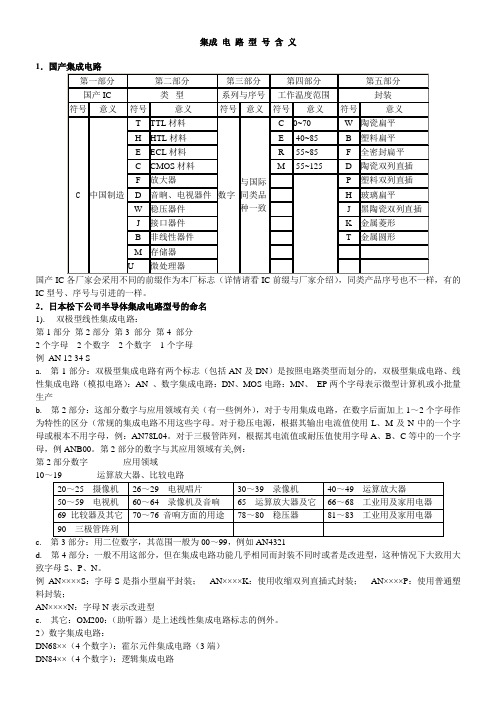
集成电路型号含义1.国产集成电路第一部分第二部分第三部分第四部分第五部分国产IC类型系列与序号工作温度范围封装符号意义符号意义符号意义符号意义符号意义C 中国制造T TTL材料数字与国际同类品种一致C0~70W陶瓷扁平H HTL材料E-40~85B塑料扁平E ECL材料R-55~85F全密封扁平C CMOS材料M-55~125D陶瓷双列直插F放大器P塑料双列直插D音晌、电视器件H玻璃扁平W稳压器件J黑陶瓷双列直插J接口器件K金属菱形B非线性器件T金属圆形M存储器U 微处理器国产IC各厂家会采用不同的前缀作为本厂标志(详情请看IC前缀与厂家介绍),同类产品序号也不一样,有的IC型号、序号与引进的一样。
2.日本松下公司半导体集成电路型号的命名1). 双极型线性集成电路:第1部分第2部分第3 部分第4 部分2个字母2个数字2个数字1个字母例AN 12 34 Sa.第1部分:双极型集成电路有两个标志(包括AN及DN)是按照电路类型而划分的,双极型集成电路、线性集成电路(模拟电路):AN 、数字集成电路:DN、MOS电路:MN、EP两个字母表示微型计算机或小批量生产b.第2部分:这部分数字与应用领域有关(有一些例外),对于专用集成电路,在数字后面加上1~2个字母作为特性的区分(常规的集成电路不用这些字母。
对于稳压电源,根据其输出电流值使用L、M及N中的一个字母或根本不用字母,例:AN78L04。
对于三极管阵列,根据其电流值或耐压值使用字母A、B、C等中的一个字母,例ANB00。
第2部分的数字与其应用领域有关,例:第2部分数字应用领域10~19 运算放大器、比较电路20~25 摄像机26~29 电视唱片30~39 录像机40~49 运算放大器50~59 电视机60~64 录像机及音响65 运算放大器及它66~68 工业用及家用电器69 比较器及其它70~76 音响方面的用途78~80 稳压器81~83 工业用及家用电器90 三极管阵列c.第3部分:用二位数字,其范围一般为00~99,例如AN4321d.第4部分:一般不用这部分,但在集成电路功能几乎相同而封装不同时或者是改进型,这种情况下大致用大致字母S、P、N。
集成产品开发流程(IPD)实战应用 For 浪潮集团

4
《集成产品开发流程(IPD)实战应用》培训班
2
项目管理 研发管理 产品管理 领航者
中国企业产品开发管理的典型问题
1 缺乏系统、正确的产品管理理念 2 缺乏前瞻性、有效的产品规划 3 在产品全生命周期过程中缺乏例行的系统的业务决策评审 4 职能化特征明显的组织结构阻碍了跨部门的协作 5 不规范、不一致、串行的产品开发流程 6 项目管理薄弱(包括进度、质量、成本、风险等) 7 技术开发与产品开发未分离,缺乏技术规划与运作机制 8 缺乏共用模块(CBB)与经验教训的积累及共享机制 9 缺乏有效的产品导向的考评和激励机制 10 缺乏有效的培养机制,产品管理人员的职业化素质不足
成功标准/关 注点
结构
流程
项目管理
产品战略及 规划
级别L1 不明确的目标
不明确、不清晰 无纪律状态 无原则性 无
级别L2 不一致的目标
职能化 各职能的工作流程 协调不畅 无原则、流于形式
级别L3 产品取得市场 成功 跨部门团队 统一的跨部门流程 高效协作
有效引导产品开发
级别L4 以平台推动产品持续 成功 异步开发的组织平台 流程成为战略优势 管道平衡、高效
15
活动 2
活动 3
客户需求 被满足
• 狭义的产品:指具有某种特定物质形状和用途的物品,是看得见、摸得着的 东西。
• 广义的产品:即指产品包,指人们通过购买而获得的能够满足某种需要和欲 望的物品总和,它既包括具有物质形态的产品实体,又包括非物质形态的利益。
品牌 安装
核心产品占总 成本的80%
包装
心理产品 附加产品 有形产品 核心产品
指导 质量
《集成产品开发流程(IPD)实战应用》培训班
集成产品开发(IPD)高层培训
产品开发是投资行为 基于市场的创新 基于平台的异步开发模式和重用策略 技术开发与产品开发分离 跨部门协同 结构化的并行开发流程 产品线与能力线并重 职业化人才梯队建设
IPD整体框架
计划
概念
制定市场
细分策略
调整
&
优
理解市场
市场细分
组合分析
制定细分市场策略及计划
调整/优化业务计划
租赁公司
(功能管理)
总经理
电气公司
(功能管理)
总经理
管道公司
(功能管理)
总经理
核心组
外围组
PDT中的角色构成(举例)
IPMT
PDT1
PDT2
PDT3
LPDT
RDPDT
MKPDT
FPDT
PROPDT
MNPDT
TSPDT
EE
SWE
ME
IDE
MOPS
PP
AME
TSS
TSS
EE
SWE
EE
SWE
ME
IDE
EE
跨部门的团队
结构化流程
高效的 研发体系
+
-
-
+
+
优化投资组合
IPD能给企业带来什么好处?
通过成功实施IPD的要素,能给公司带来典型好处: 产品投入市场时间缩短40%~60%; 产品开发浪费减少50%~80%; 产品开发生产力提高25%~30%; 新产品收益(占全部收益的百分比)增加100% (来自国际著名PRTM咨询公司的统计)
Proc
Dev
Mfg
Mkt
Svc
Fin
SW
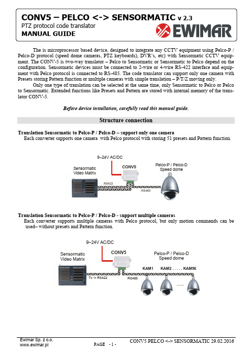
Pelco-P Pelco-D与Sensormatic集成设备说明书
The is microprocessor based device, designed to integrate any CCTV equipment using Pelco-P / Pelco-D protocol (speed dome cameras, PTZ keyboards), DVR’s, etc) with Sensormatic CCTV equip-ment. The CONV-5 is two-way translator – Pelco to Sensormatic or Sensormatic to Pelco depend on the configuration. Sensormatic devices must be connected to 2-wire or 4-wire RS-422 interface and equip-ment with Pelco protocol is connected to RS-485. The code translator can support only one camera with Presets storing Pattern function or multiple cameras with simple translation – P/T/Z moving only.Only one type of translation can be selected at the same time, only Sensormatic to Pelco or Pelco to Sensormatic. Extended functions like Presets and Pattern are stored with internal memory of the trans-lator CONV-5.Before device installation, carefully read this manual guide.Structure connectionTranslation Sensormatic to Pelco-P / Pelco-D – support only one cameraEach converter supports one camera with Pelco protocol with storing 51 presets and Pattern function.Sensormatic Video MatrixRS485RS422Pelco-P / Pelco-D Speed domeCONV59~24V AC/DCTranslation Sensormatic to Pelco-P / Pelco-D - support multiple camerasEach converter supports multiple cameras with Pelco protocol, but only motion commands can be used– without presets and Pattern function.Sensormatic Video MatrixRS485Tx -> RS422Pelco-P / Pelco-D Speed domeCONV5-D9~24V AC/DC......KAM1KAM2 . . . . .KAM96CONV5 – PELCO <-> SENSORMATICTranslation Pelco to Sensormatic – support only one cameraEach converter supports one camera of Sensormatic, with 51 presets stored in the CONV or 96 presets if can be stored in camera (depend for camera type) and Pattern function. Some Sensormatic cameras support only 6 presets stored in camera memory, then up to 51 presets can be stored in converter mem-ory.Pelco-D/P keyboardRS485RS422SENSORMATIC Speed domeCONV59~24V AC/DCTranslation Pelco to Sensormatic – support multiple camerasEach converter supports multiple cameras with Sensormatic protocol, but only motion commands can be used– without Presets and Pattern function.Pelco-D/P keyboardRS485SENSORMATIC Speed dome CONV59~24V AC/DCKAM1KAM2 . . . . . .KAM96RS-422 -> RxSwitches and connection terminalCHANGE CONFIGURATIONDIP switches are used to configuration of the CONV5. To change most configurations, power supply must be disconnected from the unit. Other some changes will no have the effect.OFF (UP)ON(DOWN)CONNECTION TERMINALLED1 – Transmission indication of translationLED2 – Transmission indication of input dataLED lights are flashing due the time of transmission in proper protocols. The lack of flashing means connection error or converter switches setting.P o w e r P o w e r R S 485 - A +R S 485 - B -G N D S e n s o r m a t i c T e r m 1R S 422 R x +R S 422 R x -R S 422 T x -R S 422 T x +TRANSLATION SENSORMATIC TO PELCOCONNECTIONS FOR ONE CAMERA SUPPORT MODEP o w e r P o w e r R S 485 - A +R S 485 - B -G N D T e r m 1R S 422 R x +R S 422 R x -R S 422 T x -R S 422 T x +T o Pelco D / P Speed DomeTx+Tx-Rx+Rx-From RS422 port Video Matrix (Sensormatic)Above drawing explains how to connect one camera in mode. Then Preset and Pattern will be available. For this mode 4-wire connection of RS-422 bus is used. We suggest to place translator direct at Sensormatic Video Matrix. If more Pelco cameras is needed to connect in this mode, one translator per one camera must be used. Everything translators must be connected in the same port of Sensormatic Video MatrixPower Supply: 9~24V DC / ACSensormaticRS-422, used to connect converter to Sensormatic Video Matrix or Sensormatic Speed Some – depend on configurationPelco P /DRS-485, used to connect Pelco Speed Dome,(Pelco-D or Pelco-P protocol) with PTZ keyboard with Pelco.GND: These are terminals for connecting the shielding of theRS-485(cable shield).For long cables of RS-485 bus, should be connected to termi-nating resistor (120 Ohm). This will prevent wave reflections in cables, which are cause of transmission errors.Terminating resistors should be connected only on first and last devices. To many resistors can overload RS-485 driver.The CONV-5 translator have internal resistor only for RS-485port. To close terminating resistor please make wire link be-tween TERM and A+ terminals. For RS-422 must be used external resistors between + and – terminal – only when cables are longer than 50m.CONNECTIONS FOR MULTIPLE CAMERASP o w e r P o w e r R S 485 - A +R S 485 - B -G N D T e r m 1R S 422 R x +R S 422 R x -R S 422 T x -R S 422 T x +T o Pelco D / P Speed DomeTx+Tx-From RS422 port Video Matrix (Sensormatic)Above drawing explains how to connect many cameras to one converter. Because at this mode memory of converter can't uses, Presets or Pattern functions are not available.For connection in this mode only two wires of RS-422 port is needed. Converter will operate camera ad-dresses 1-96 (depend on matrix switcher configuration).GENERAL CONFIGURATION FOR TRANSLATION SENSORMATIC TO PELCODescription of switches:Transmission speed Pelco camera2400baud 4800baud 9600baud 19200baud DIP 1 OFF ON OFF ON DIP 2 OFF OFF ON ONSwitches defines transmission baud rate for Pelco-P / Pelco-D camera.Output protocol Pelco-D Pelco-PDIP 3 OFF ONSwitch defines type of output protocol for Pelco.Presets 1, 49, 59 used to Pattern supportNot active Active DIP 4 OFF ONWhen function is active:Call preset No1 - run programmed Pattern.Call preset No 49 - start programming Pattern with full range of speed movement Call preset No 50 - stop programming Pattern.Notice! Before use presets 1, 49, and 50 they must be stored in the video matrixConversion mode Pelco to Sensormatic Sensormatic to PelcoDIP 5 ONTo get translation from Sensormatic to Pelco, DIP No5 must be ON during change configuration.Delay between commands Short LongDIP 7 OFF ONSometimes when Pelco camera can't receive too many data, can work instable. In this situation DIP 6 should be ON to intro-duce 100ms delay between each commands. Normally should be OFF to fastest reaction.Saving configurationDIP 8 To save configuration, must be turned ONHOW TO SET GENERAL CONFIGURATION1. Disconnect power supply from the CONV52. Set the switches DIP 8 and DIP 5 to ON position.3. Set other switches as you need4.Connect power supply into the CONV5 continue on next page >>>5. Wait until red LED will start flashing, then disconnect a power supply.6. Set the switch DIP 8 to OFF position – (DIP 5 leave ON)7. Connect power supply into the CONV5.SELECT CONFIGURATION FOR ONE CAMERA OT MULTIPLE CAMERASSetting address determines support one camera or multiple cameras. When address is set as NONE trans-lator dues support multiple cameras. When any address is set, translator does support one camera with determined address. Address is binary set in according to the following table.1. Disconnect power supply from the CONV52. Set the switches 1~8 (DIP 8 must be OFF).3. Set address required address (for multiple cameras “NONE” – DIP1-7 OFF)4.Connect power supply into the CONV5If you want to change address again, please reply steps 1-4.Address1 2 3 4 5 6 7 8 Address 1234567847 ● ● ● ● ● 48 ● ● 49 ● ● ● NONEAll TURNED OFF – mean supportmultiple camera50 ● ● ● 1 ● 51 ● ● ● ● 2 ● 52 ● ● ● 3 ● ● 53 ● ● ● ● 4 ● 54 ● ● ● ● 5 ● ● 55 ● ● ● ● ● 6 ● ● 56 ● ● ● 7 ● ● ● 57 ● ● ● ● 8 ● 58 ● ● ● ● 9 ● ● 59 ● ● ● ● ● 10 ● ● 60 ● ● ● ● 11 ● ● ● 61 ● ● ● ● ● 12 ● ● 62 ● ● ● ● ● 13 ● ● ● 63 ● ● ● ● ● ● 14 ● ● ● 64 ● 15 ● ● ● ● 65 ● ● 16 ● 66 ● ● 17 ● ● 67 ● ● ● 18 ● ● 68 ● ● 19 ● ● ● 69 ● ● ● 20 ● ● 70 ● ● ● 21 ● ● ● 71 ● ● ● ● 22 ● ● ● 72 ● ● 23 ● ● ● ● 73 ● ● ● 24 ● ● 74 ● ● ● 25 ● ● ● 75 ● ● ● ● 26 ● ● ● 76 ● ● ● 27 ● ● ● ● 77 ● ● ● ● 28 ● ● ● 78 ● ● ● ● 29 ● ● ● ● 79 ● ● ● ● ● 30 ● ● ● ● 80 ● ● 31 ● ● ● ● ● 81 ● ● ● 32 ● 82 ● ● ● 33 ● ● 83 ● ● ● ● 34 ● ● 84 ● ● ● 35 ● ● ● 85 ● ● ● ● 36 ● ● 86 ● ● ● ● 37 ● ● ● 87 ● ● ● ● ● 38 ● ● ● 88 ● ● ● 39 ● ● ● ● 89 ● ● ● ● 40 ● ● 90 ● ● ● ● 41 ● ● ● 91 ● ● ● ● ● 42 ● ● ● 92 ● ● ● ● 43 ● ● ● ● 93 ● ● ● ● ● 44 ● ● ● 94 ● ● ● ● ● 45 ● ● ● ● 95 ● ● ● ● ● ● 46●●●●OFF96●●OFF● – Mean switch is TURNED ONFor one camera support mode number of camera controlled from matrix switcher, converter address and camera address with Pelco protocol must be the same, other way operating is not possible. Only exception are cameras with Pelco-P, which received address must be lower than that indicated on the settings made in it.START-UP FOR SENSORMATIC TO PELCO TRANSLATIONMake sure if polarization of RS-485 or RS-422 interfaces is correct.Correct operation of the translator can be determined by observing the LEDs. The green LED flashes when data from the matrix are interpreted correctly by the converter. The red LED indicates that the received data has been converted and transmitted to the camera with Pelco protocol.To make sure camera is properly detected, in system can not exist camera with the same ID address on Sensornet or Manchester bus.At 4 wire connection of RS-422 configuration converter is automatically detected as RS-422 Ultra Dome camera. At 2-wire mode type of camera must be set manually in the Video Matrix as below.SET VIDEO MATRIX IN MULTIPLE CAMERA SUPPORT MODE:To proper work in multiple mode, you should set model …SD ULTRA 3,4 or 5 (422)”manually in Sen-sormatic Video Matrix. To do that we should:Example for VM96 matrix switcher1. Enter menu: Config -> Cameras.2. Press ALT + S, select GoTo and confirm by pressing ENTER.3. Select from the list the type of camera that will be changed and press ENTER.4. Go to the "Camera Type" and delete the position by pressing the DEL.5. Move the arrow down one row below.6. Return the up arrow to the "Camera Type" - a list of cameras to choose from is displayed. Youmust select from a list of camera "SD ULTRA 3.4 or 5 (422)" and confirm with Enter.7. Exit the menu and reselect by Touch Tracker keyboard the camera you want to control.To change the settings for other cameras, repeat steps 2 ~ 6.The second way to set up the camera is connect the converter as in for one camera (4-wire connection) mode and set the camera address to be controlled by the converter. These types of camera will be automatically detected and set in the matrix.1. Connect the RS-422 bus as for CONV5-A mode - 4 wires.2. Disconnect the power supply of converter.3. Set by switches on converter the number of the camera to be controlled by it - identically as forCONV-A mode.4. Select on the Touch Tracker keyboard the camera number that has been set.5. Connect the power supply to converter.6. Wait until the on monitor appears Camera XX is ONLINE (XX is the number of the camera)7. Disconnect the power supply of converter.8. Set on the converter switches for CONV5-D mode.9. Connect the power supply to converter.To change the settings for other cameras, repeat steps 2 ~ 6. 4-wire connection can stay, it will not affect the operation of the system.OPERATING AT TRANSLATION SENSORMATIC TO PELCO MODEMotion controlMotion control is fully accessible via the TouchTracker keyboard in accordance with their instructions. At the same time can be used to control the direction of the camera and the lens (aperture, focus and and zoom).Pattern function support (only camera support mode)By the CONV5 can be saved one Pattern in Pelco camera – by way described in manual of Touch tracker and Video Matrix. While programming the Pattern rotation speed is reduced twice, which is imposed by the Video Matrix of Sensormatic. The converter support only the first Pattern on the list created for each camera in the Video Matrix, another Patterns are ignored.Preset function support (only camera support mode)In CONV5 we can programed 50 presets (View) + preset 95, which in cameras with Pelco protocol is used to Entry Menu.Starting Preset (View) works in accordance with to the instructions for TouchTracker keyboard.To program a preset, follow the steps below. DO NOT disconnect a power supply during below operations1. Remember current settings of the switches on the converter.2. Use the TouchTracker keyboard to set the camera in the desired position.3. Select the preset number (DIP 1-7) on the converter and turn on the switch No. 8.4. Save the preset using the TouchTracker keyboard.5. Set the switches to the previous position and turn off the switch no.To program the other presets, repeat steps 2 ~ 4.Preset 1 2 3 4 5 6 7 8 Preset 1 2 3 4 5 6 7 8●31 ●●●●●●NoneInactive 32 ●●1 ●●33 ●●●2 ●●34 ●●●3 ●●●35 ●●●●4 ●●36 ●●●5 ●●●37 ●●●●6 ●●●38 ●●●●7 ●●●●39 ●●●●●8 ●●40 ●●●9 ●●●41 ●●●●10 ●●●42 ●●●●11 ●●●●43 ●●●●●12 ●●●44 ●●●●13 ●●●●45 ●●●●●14 ●●●●46 ●●●●●15 ●●●●●47 ●●●●●●16 ●●48 ●●●17 ●●●49 ●●●●18 ●●●50 ●●●●19 ●●●●95 ●●●●●20 ●●●21 ●●●●22 ●●●●23 ●●●●●24 ●●●25 ●●●●26 ●●●●27 ●●●●●Preset No 95 usually is used to entry to menu of Pelcocamera.Before use this preset must be stored in Video matrix28 ●●●●29 ●●●●●30 ●●●●●● – Switch TURNED ONTRANSLATION PELCO TO SENSORMATICCONNECTIONS FOR ONE CAMERA SUPPORT MODEP o w e r P o w e r R S 485 - A +R S 485 - B -G N D T e r m 1R S 422 R x +R S 422 R x -R S 422 T x -R S 422 T x +From Pelco PTZ keyboardTx+Tx-Rx+Rx-T o RS-422 port in Sensormatic Speed DomeAbove drawing explains how to connect one camera in mode, which supports Preset and Pattern function. For this mode 4-wire connection of RS-422 bus is used. We suggest to place translator direct at Sensormatic Speed Dome. If more Sensrmatic cameras is needed to connect in this mode, one translator per one camera must be used.CONNECTIONS FOR MULTIPLE CAMERASP o w e r -P o w e r R S 485 - A +R S 485 - B -G N D T e r m 1R S 422 R x +R S 422 R x -R S 422 T x -R S 422 T x+From Pelco PTZ keyboardRx+Rx-T o RS-422 port in Sensormatic Speed DomeAbove drawing explains how to connect many cameras with a single converter. Because in this mode memory of converter can not be used, Presets or Pattern functions are not available.For connection in this mode, only two wires of RS-422 port is needed. Converter will operate camera addresses 1-254 .GENERAL CONFIGURATION FOR TRANSLATION PELCO TO SENSORMATIC1. Disconnect power supply from the CONV52. Set the switches DIP 8 and DIP 5 to OFF position.3. Set other switches as you need4.Connect power supply into the CONV55. Wait until red LED will start flashing, then disconnect a power supply.6. Set the switch DIP 8 to OFF position – (DIP 5 leave OFF)7. Connect power supply into the CONV5Description of switches:2400baud 4800baud 9600baud 19200baud Transmission speedFor Pelco cameraDIP 1 OFF ON OFF ONDIP 2 OFF OFF ON ONSwitches define transmission speed for Pelco-P / Pelco-D keyboard.Input protocol Pelco-D Pelco-PDIP 3 OFF ONConversion mode Pelco to Sensormatic Sensormatic to PelcoDIP 5 OFFTo get translation from Pelco to Sensormatic, DIP No5 must be OFF during change configuration.Storing of Presets Preset will be stored in Camera Preset will be stored in ConverterDIP 6 OFF ON Up to 96 presets can be stored in the Camera (if camera support preset storing). Up to 51 presets can be stored in the con-verter. Set Preset 95 always is used to entry camera menu, call preset 95 always is used to exit camera menu (if camera sup-ports it).Delay between commands Short LongDIP 7 OFF ON Sometimes when Pelco keyboard send too many data, Sensormatic camera can have problems with STOP. In this situationDIP 6 should be ON to introduce 100ms pause between each commands. Normally should be OFF.Saving configurationDIP 8 To save configuration, must be turned ONWARNING! If the CONV5 worked at Sensormatic to Pelco mode before, everything stored presets can be deleted.SELECT CONFIGURATION FOR ONE CAMERA OT MULTIPLE CAMERASSetting address determines support one camera or multiple cameras. When address is set as NONE trans-lator does support multiple cameras. When any address is set, translator does support one camera withdetermined address. Address is binary set in according to the following table on PAGE 5.START-UP FOR PELCO TO SENSORMATIC TRANSLATIONMake sure if polarization of RS-485 or RS-422 interfaces is correct.Correct operation of the translator can be determined by observing the LEDs.The green LED indicates that the received data has been converted and transmitted to the camera withPelco protocol. The red LED flashes when data from the keyboard are translated and send to camera.OPERATING IN TRANSLATION SENSORMATIC TO PELCO MODEMotion controlUsing for each keyboard, in accordance with its user guide. At the same time can be controlled Pan, Tilt, and Zoom.Support Pattern functionBy the CONV5 can be saved one Pattern in Sensormatic camera – by way described in manual of Pelco PTZ keyboard. While programming the Pattern speed of rotation is reduced to 2 speeds – this is typicall for Sensormatic cameras. The converter support only one Pattern. The pattern working in loop mode after start.Support Preset functionIn CONV5 we can stored 51 presets (saved in converter memory) or up to 96 presets (saved in camera memory). It depend for camera model.。
PF2M7-TF2Z038EN 数字流量开关 - 集成型 PF2M7## 系列说明书
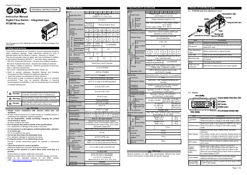
Instruction ManualPF2M7## seriesThe intended use of the digital flow switch is to monitor and display flow information.These safety instructions are intended to prevent hazardous situations and/or equipment damage. These instructions indicate the level of potential hazard with the labels of “Caution,” “Warning” or “Danger.”They are all important notes for safety and must be followed in addition to International Standards (ISO/IEC) *1), and other safety regulations. *1)ISO 4414: Pneumatic fluid power - General rules relating to systems. ISO 4413: Hydraulic fluid power - General rules relating to systems.IEC 60204-1: Safety of machinery - Electrical equipment of machines. (Part 1: General requirements)ISO 10218-1: Manipulating industrial robots -Safety. etc.Refer to product catalogue, Operation Manual and Handling Precautions for SMC Products for additional information. Keep this manual in a safe place for future reference.This product is class A equipment intended for use in an industrial environment. There may be potential difficulties in ensuring electromagnetic compatibility in other environments due to conducted or radiated disturbances.WarningAlways ensure compliance with relevant safety laws and standards.All work must be carried out in a safe manner by a qualified person in compliance with applicable national regulations.Do not disassemble, modify (including changing the printed circuit board) or repair. An injury or failure can result.Do not operate the product outside of the specifications. Fire, malfunction or damage to the product can result.Do not operate in an atmosphere containing flammable, explosive or corrosive gas.Fire or an explosion can result.Do not use the product for flammable fluids. Fire, explosion, damage or corrosion can result. If using the product in an interlocking circuit:Provide a double interlocking system, for example a mechanical system.Check the product for correct operation.Otherwise malfunction can result, causing an accident.Do not use the product in a place where static electricity is a problem.Product failure or system malfunction may result.Otherwise electric shock, malfunction or product damage can result. Refer to the operation manual on the SMC website (URL: https:// ) for more safety instructions.2 SpecificationsWarningSpecial products (-X) might have specifications different from those shown in this section. Contact SMC for specific drawings.3.1 PF2M7## (with flow adjustment valve)3.2 DisplayORIGINAL INSTRUCTIONSThe product code is displayed for approximately 3 seconds afterpower is supplied.Then measurement mode will be displayed and the switchoperation will start.4.1 InstallationWarningDo not install the product unless the safety instructions have been read and understood.Use the product within the specified operating pressure and temperature range.Proof pressure could vary according to the fluid temperature. Check the characteristics data for operating pressure and proof pressure.4.2 EnvironmentWarningDo not use in an environment where corrosive gases, chemicals, salt water or steam are present.Do not use in an explosive atmosphere.Do not expose to direct sunlight. Use a suitable protective cover.Do not install in a location subject to vibration or impact in excess of the product’s specifications.Do not mount in a location exposed to radiant heat that would result in temperatures in excess of the product’s specifications.Refer to the flow direction of the fluid indicated on the product for installation and piping.Do not mount the body with the bottom facing upwards. Retention of air can cause inability to measure accurately.Do not insert metal wires or other foreign matter into the piping port. This can damage the sensor causing failure or malfunction.Never mount a product in a location that will be used as a foothold. The product may be damaged if excessive force is applied by stepping or climbing onto it.If there is a risk of foreign matter entering the fluid, install and pipe a filter or mist separator at the inlet to avoid failure and malfunction. Otherwise damage or malfunction can result. 4.3 Panel mountingInsert panel mount adapter B (supplied as an accessory) into section A of the panel mount adapter.Push panel mount adapter B from behind until the display is fixed onto the panel.The bracket pin engages the notched part of panel adapter section C to fix the display.The switch can be mounted on a panel with a thickness of 1 to 3.2 mm.4.4 Bracket mountingMount the bracket using the mounting screws supplied. The required tightening torque is 0.42 ±0.04 N•m.Install the product (with bracket) using the M3 screws (4 pcs.). Bracket thickness is approximately 1.2 mm.4.5 DIN rail mounting (using ZS-33-R#)Mount the DIN rail mounting parts using the mounting screws and joint screws supplied.The required tightening torque of the DIN rail mounting screws and joint screws is 0.4 ±0.05 N•m.Refer to the operation manual on the SMC website (URL: https:// ) for all mounting dimensions.4.6 PipingCautionBefore connecting piping make sure to clean up chips, cutting oil, dust etc. Ensure there is no leakage after piping.Any dust left in the piping should be flushed out by air blow before connecting piping to the product.Otherwise damage or malfunction can result.For piping of the product, hold the piping with a wrench on the metal part of the product.Holding other parts of the product with a wrench may damage the product.4.7 WiringCautionDo not perform wiring while the power is on. Confirm proper insulation of wiring.Do not route wires and cables together with power or high voltage cables. Otherwise the product can malfunction due to interference of noise and surge voltage from power and high voltage cables to the signal line. Keep wiring as short as possible to prevent interference from electromagnetic noise and surge voltage. Do not use a cable longer than 30 m. When using it as an IO-Link device, do not use a cable longer than 20 m.Ensure that the FG terminal is connected to ground when using a commercially available switch-mode power supply.When the analogue output is used, install a noise filter (line noise filter, ferrite element, etc.) between the switch-mode power supply and this product.Connecting / DisconnectingWhen mounting the connector, insert it straight into the socket, holding the lever and connector body, and push the connector until the lever hooks into the housing, and locks.When removing the connector, press down the lever to release the hook from the housing and pull the connector straight out.Connector pin numbers (on the lead wire)•Lead wire and connector (ZS-33-D)•M12 conversion lead wire (ZS-33-DM)Power is supplied: The outputs will continue to operate during setting.: Simple settingmode and function selection mode settings are reflected each other.6 Flow Setting6.1 Switch operationWhen the flow exceeds the set value, the switch will be turned ON.When the flow falls below the set value by the amount of hysteresis or more, the switch will be turned OFF.The default setting is to turn on the flow switch when the flow reaches the centre of the upper limit of the rated flow range.If the operation shown below is acceptable, keep this setting.: For hysteresis refer to [F 1] Setting of OUT1 and [F 2] Setting of OUT2.Without flow adjustment valve (using ZS-33-M) With flow adjustment valve (using ZS-33-MS) Press the SETbutton for 5 seconds or longerPress the SET button between 2 to 5 secondsPress the SET button once[Simple setting mode (Hysteresis mode)]In the Simple setting mode, the set value and hysteresis can be changed. (1) Press the SET button once in measurement mode.[P_1] or [n_1] and the [current set value] are displayed alternately.(2) Change the set value using the UP or DOWN button and press the SET button to set the value. Then, the setting moves to hysteresis setting (The snap shot function can be used). Press the UP button continuously to keep increasing the set value.Press the DOWN button continuously to keep decreasing the set value.(3) [H_1] and the current set value are displayed in turn.(4) Change the hysteresis by pressing the UP or DOWN button and press the SET button. Setting is completed and the product returns to measurement mode (The snap shot function can be used).For models with switch outputs for both OUT1 and OUT2, [P_2] or [n_2] will be displayed. These are set simultaneously.After enabling the setting by pressing the SET button, it is possible to return to measurement mode by pressing the SET button for 2 seconds or longer.When hysteresis mode is not used, "Input set value” is displayed. The set value and hysteresis settings limit each other.For more detailed setting, set each function in function selection mode.8.1 Function selection modeIn measurement mode, press the SET button for 2 to 5 seconds to display [F 0] on the display.Select to display the function to be change [F ].Press the SET button for 2 seconds or longer in function selection mode to return to measurement mode. : Some products do not have all the functions. If a function is not available or selected due to configuration of other functions, [- - -] is displayed.8.2 Default settings: Setting is only possible for models with the units selection function. : Only available for models with switch outputs for both OUT1 and OUT2.: This function is available for models with analogue output. Analogue free span function can be selected.: This function is available in IO-Link compatible products. : This function is available for models with external input.9 Other SettingsSnap shot functionPeak/bottom value indication ResetKey-lock functionZero clear functionRefer to the operation manual on the SMC website(URL: https:// ) for setting these functions.10.1 General MaintenanceCautionNot following proper maintenance procedures could cause the product to malfunction and lead to equipment damage.If handled improperly, compressed air can be dangerous.Maintenance of pneumatic systems should be performed only by qualified personnel.Before performing maintenance, turn off the power supply and be sure to cut off the supply pressure. Confirm that the air is released to atmosphere.After installation and maintenance, apply operating pressure and power to the equipment and perform appropriate functional and leakage tests to make sure the equipment is installed correctly.If any electrical connections are disturbed during maintenance, ensure they are reconnected correctly and safety checks are carried out as required to ensure continued compliance with applicable national regulations.Do not make any modification to the product.Do not disassemble the product, unless required by installation or maintenance instructions.How to reset the product after a power cut or when the power has been unexpectedly removedThe settings of the product are retained from before the power cut or de-energizing.The output condition also recovers to that before the power cut or de-energizing, but may change depending on the operating environment. Therefore, check the safety of the whole system before operating the product.11 How to OrderRefer to drawings/catalogue on the SMC website (URL: https:// ) for ‘How to Order’ information.12 Outline Dimensions (mm)Refer to the operation manual on the SMC website(URL: https:// ) for outline dimensions.13.1 Error indicationIf the error cannot be reset after the above measures are taken, or errors other than above are displayed, please contact SMC.Refer to the operation manual on the SMC website (URL: https://) for more detailed information about troubleshooting. 14.1 Limited warranty and Disclaimer/Compliance RequirementsRefer to Handling Precautions for SMC Products.15 Product disposalThis product should not be disposed of as municipal waste. Check yourlocal regulations and guidelines to dispose this product correctly, in orderto reduce the impact on human health and the environment.16 ContactsRefer to or www.smc.eu for contacts.URL: https:// (Global) https://www.smc.eu (Europe)SMC Corporation, 4-14-1, Sotokanda, Chiyoda-ku, Tokyo 101-0021, JapanSpecifications are subject to change without prior notice from the manufacturer.© 2021SMC Corporation All Rights Reserved.Template DKP50047-F-085M。
PDM与ERP、CAPP系统集成的接口设计--以常德烟草机械有限责任公司为例

的实现还是通过 纸质 文件传达 , 信息 沟通 不及时 , 拉长 了处
理 、 策 、 施 的 时 间 ;r It l k系 统 只 是 一 个 项 目 组 级 决 实 Po nr i / an 的 管 理 平 台 。 乏 项 目管 理 功 能 , 时 工 作 流 的 管 理 以 及 技 缺 同
R suc ln ig' 传统的制造资源计 划拓展 为围绕市场 eorePann )  ̄ 需求而建立 的企 业 内外部 资源计划 系统 . 客户需求和食业 将
内 部 的 经 营 活 动 以 及 供 应 商 的资 源 融 合 在 一 起 . 现 了 以客 ・ 体
术 文档资料 的管理欠 缺 ;产 品配置是 在 MR I 系统 中开发 PI
P M系统与 E PC P D R 、 A P系统 集 成 以后 , 司各 设 计 部 门 公
将 不再 使 用 目前 E P信 息 系统 中 的 E D 7系统 ( R P9 即基 础 数
期 . 有 效 地将 产 品数 据 从 概 念设 计 、 能 计算 分 析 、 细 设 计 、 详 工 艺 流 程设 计 、 工制 造 、 维 护 , 至产 品 消亡 的整 个 生命 周 加 销售 直 期 内及其 各 阶段 的 相关 数 据 ,按 照一 定 的管 理模 式 加 以定 义 、 组 织 和 管 理 . 产 品数 据 在 其 整 个 生 命 周 期 内 保 持 一致 、 享 使 共 及 安 全 。 能 很好 地 促 进企 业 提高 其 产 品质 量 , 短研 制 周期 , 它 缩
据管 理系统 ) 。零部 件 的配置结 构 和维 护设计 数据都 将在
P DM 系 统 中进 行 。 如何 将 P M 的 数 据 与 C P D A P的 工 艺 数 据
CMMI基础知识培训讲义
CMMI基础知识一、CMMI简介CMMI(Capability Maturity Model Integration,能力成熟度模型集成)是用于产品开发(或服务)的过程改进成熟度模型。
CMMI的最佳实践覆盖了产品构思、交付和维护的整个生命周期。
CMMI源自于CMM。
1984年美国国防部为了降低采购风险,委托卡耐基—梅隆大学软件工程研究院(SEI)制定了软件过程改进、评估模型,也称为SEI SW—CMM。
该模型于1991年正式推出,迅速得到广大软件企业及其顾客的认可.经过不断研究,相继推出了其他领域的CMM模型,比如:(1) SE-CMM (System Engineering CMM): 系统工程CMM(2)SA-CMM (Software Acquisition CMM):软件采购CMM(3)IPT-CMM (Integrated Product Team CMM): 集成产品群组CMM(4) P-CMM (People CMM):人力资源能力成熟度模型之后将各种CMM模型进行整合,形成了CMMI.2002年CMMI1.1版本正式发布,并立即被广泛采用,2006年8月,面向开发的CMMI(CMMI—DEV 1。
2)版本正式发布.目前正在使用的就是这个版本。
下面讲的CMMI是指CMMI—DEV1。
2,针对软件方面的.通过上面的介绍,可以清楚地知道CMMI这几个字母的含义,CM:能力成熟度.不同的成熟度对应不同的等级,一共有五个等级;M :模型. CMMI提供一个标准的模型,企业的软件能力成熟度是否达到对应的级别,要和这个模型进行比较。
I :集成。
将各个不同领域的CMM进行抽象整合.也就是说CMMI不仅适合于软件领域,同样适合于其他领域。
二、CMMI的五个等级CMMI的阶段式表示法将成熟度划分为5个等级.除了初始级以外,每个成熟度等级都有若干个过程域,如下表所示。
由于成熟度等级是循序渐进的,如果想达到某个成熟度等级,例如CMMI 3级,除了满足CMMI 3级本身11过程域之外,还要满足CMMI 2级的7个过程域,依此类推。
面向PDM/CAPP集成的产品结构建模

关键词 : 产品结构 :PDM;cAPP;STEP:UML 中图分 类号 : _6 文献标识 码:A T卜1 6 文章编号 1 0 — 1 4 ( 0 2 2 0 4 — 4 9 0 0 3 2 0 )0 — 0 5 0 萧 健
S u y o r d t tu t e mo e ig f t d n p o uc r cur d l PDM/ s n or CAP N GRAT ON P I TE I
摘 要: 产品结掏是 PD CAP M/ P集成的主线 在总结 PD CAP M/ P几 种集成方式的基础上 ,提出了基于 S E T P和 U ML进行产品结构 信息建模的方法 。分 析了基于 STE P标准描述产品结构信息的 应用协议 ,阐述 了用 U I VL进行 P / P DM CA P产品结梅模型映射 的基 本过 程 。最后 给 出 了应用 实慢 。
维普资讯
弟l渣 訇
似
面向 PDM/i APP 耆 威 陶 = ; 葶 ;
产品结构建粳
萧 健 ’ 张 国军 , ,陈小丽 ,邵新宇
( 1广东科龙电器股份有 限公司 冰箱开发部 ,顺德 5 8 0 23 3 2华 中科技大学 机械科学与工程 学院, 武汉 4 0 7 ) 3 0 4
维普资讯
务I谴 甸 砷 m
cAD 与 cAM 的桥 梁 ,又是 联系 工程 设计 生 产 j
管理 的纽带 P DM 和 C P的集成 主要 有 以下几 AP 种方 式: c) 】应用封 装( AE:Ap La in E c p uain pi t n a s lt ) c o o
p o u tU u e mo ei g me h db s d o TEP a d UM L T rd c sFc r d l to a e nS t t n n ¨S EP b s d a p ia i n —a e p l t c o D o o o s u e e c ii g p o u t tu t r f r t n a e ds u s d Th a i r t c l s d i d s b n r d c r c u e i O ma i r ic s e . e b sc n r s n o p o e u e o p ig p o u t tu t r d l e we n P rc d r f ma p n r d c r c u e mo e t e DM a d CAPP i ye d d A s b n i le . t s I s . n a p ia i n i s a c ie . a t a p l t t n e i gv n c o n S Ke y wor : r d c t c u e P ds p o u t r t r ; DM: s u CAP ; TEP UM L P S ;
p沟道增强型场效应晶体管,肖特基二极管集成芯片
p沟道增强型场效应晶体管,肖特基二极管集成芯片
P沟道增强型场效应晶体管(P-channel, Enhancement-type MOSFET)是一种主要应用于集成电路中的晶体管,它的工作原理是基于P沟道MOSFET的结构和特性。
P沟道增强型场效应晶体管可以控制电流的通过,使其可以在集成电路中实现逻辑运算、放大信号等功能。
肖特基二极管(Schottky diode)是一种特殊的二极管,它的结构与普通的PN结二极管不同。
肖特基二极管利用金属与半导体的接触特性,具有低电压降、快速开关等优点,通常应用在高频电路、低功耗电路等场景中。
肖特基二极管集成芯片,则是将肖特基二极管与其他器件(比如晶体管、电阻等)集成在同一芯片中,以实现更高集成度和更好的性能。
肖特基二极管集成芯片可以用于模拟电路、功率电路、射频电路等各种应用领域。
基于P-PROCE集成多视图模型的产品开发过程管理
基于P-PROCE集成多视图模型的产品开发过程管理
李小燕;刘敬军;张琴舜
【期刊名称】《机械科学与技术》
【年(卷),期】2000(019)002
【摘要】无
【总页数】3页(P336-338)
【作者】李小燕;刘敬军;张琴舜
【作者单位】无
【正文语种】中文
【相关文献】
1.基于集成产品开发和集成能力成熟度模型的整合方案 [J], 章锐
2.基于CAD/CAE集成的注塑产品模型的多视图表达 [J], 熊培友;李祥;周雄辉
3.面向并行工程的集成化产品开发过程管理系统研究 [J], 曹健;张申生;等
4.面向并行工程的集成多视图产品开发模型及管理框架研究 [J], 刘敬军;张申生;全春来;陈加栋
5.基于面向对象技术的产品开发过程管理模型 [J], 项飞;宁汝新;姚珺;
因版权原因,仅展示原文概要,查看原文内容请购买。
IPD的专业术语
FGI
成品库存
FPDT
PDT财务成员
FPDT
PDT财务代表
GA
批量供货点
GA
一般可获得性
GEO/GEOS
区域/地方办事处
GP
毛利润
HL
概要的
HQ
总部
IBT
渐增构建与测试
IBT
渐增构建及测试
IPD
集成产品开发
IPD
集成产品开发
IPMT
集成组合管理团队
IRB
投资评审委员会
IRB
投资评审委员会
ISC
销售和一般管理费用
SDE
专项设计工程师
SDV
系统设计验证
SE
系统工程师
SIC
系统集成中心
SIT
系统集成测试
SPAN
战略地位分析
SPDT
PDT销售代表
SVT
系统验证测试
SWE
软件工程师
TD
资料开发工程师
TDT
技术开发团队
TDT
技术开发团队
TE
测试工程师
TPM
变革进展衡量指标
TPP
技术计划流程
TQM
全面质量管理
业务变革和信息技术
CBB
共用基础模块
CBB
共用基础模块
CCB
变更控制委员会
CDCP
概念决策评审点
CDP
并行开发流程
CEG
采购专家团
CIP
概念启动流程
CIPMT
公司级IPMT
CPD
并行产品开发
CR
变更请求
CSP
经认证的备件
DCP
决策评审点
- 1、下载文档前请自行甄别文档内容的完整性,平台不提供额外的编辑、内容补充、找答案等附加服务。
- 2、"仅部分预览"的文档,不可在线预览部分如存在完整性等问题,可反馈申请退款(可完整预览的文档不适用该条件!)。
- 3、如文档侵犯您的权益,请联系客服反馈,我们会尽快为您处理(人工客服工作时间:9:00-18:30)。
产品集成成熟度3级的工程过程域目的产品集成(Product Integration, PI) 的目的,在于将产品组件组合为产品、确保已集成的产品能适当地运作及交付产品。
业界注释产品集成过程域说明,将产品组件集成成更复杂的产品组件或完整的产品。
此过程域的范围,是依据已定义的集成顺序与程序,在一个阶段或渐进的阶段,逐渐地组合产品组件,以达成完整的产品集成。
整个过程域中,产品及产品组件的含义也包括服务及其组件。
产品集成的关键点,为产品与产品组件的内部与外部接口的管理,以确保接口间的兼容性。
在整个项目进行中,应注意接口管理。
产品集成不只是在完成设计与制造时,进行一次产品组件的组合而已。
产品集成可使用下列重复过程渐进执行,包括:组合产品组件、评估已组合的产品组件,再组合更多的产品组件。
这集成过程,首先分析与模拟(例如:相关串联、快速原型、虚拟原型及实体原型),并稳定的进展,逐渐增加更多实际的功能,直到达成最终产品。
在每一次连续的“建造”时,原型(虚拟、快速或实体)被建造、评估、改进,并基于评估过程所得到知识再建造。
虚拟对实体原型的要求程度,决定于设计工具的功能、产品的复杂度与有关的风险。
以此方式集成产品,有很高的可能性会通过产品验证与确认。
就一些产品及服务而言,最后的集成阶段,会在产品部署于预期的运作场所时进行。
相关过程域有关识别接口需求,请参考需求开发过程域,以获得更多信息。
有关定义接口与集成环境(当需要开发集成环境时),请参考技术解决方案过程域,以获得更多信息。
有关验证接口、集成环境及渐进组合的产品组件,请参考验证过程域,以获得更多信息。
有关执行产品组件与已集成产品的确认,请参考确认过程域,以获得更多信息。
有关识别风险与使用原型来降低接口兼容性及产品组件集成的风险,请参考风险管理过程域,以获得更多信息。
有关使用正式评估过程,以选择适当的集成顺序与程序及决定集成环境的采购或开发,请参考决策分析与解决方案过程域,以获得更多信息。
有关管理接口定义的变更与信息发布,请参考配置管理过程域,以获得更多信息。
有关获得产品组件或部分的集成环境,请参考供应商协议管理过程域,以获得更多信息。
特定目标及实践摘要SG 1准备产品集成SP 1.1 决定集成顺序SP 1.2 建立产品集成环境SP 1.3 建立产品集成程序与准则SG 2确保接口兼容性SP 2.1 审查接口说明的完整性SP 2.2 管理接口SG 3组合产品组件并交付产品SP 3.1 确定欲集成的产品组件已准备就绪SP 3.2 组合产品组件SP 3.3 评估已组合的产品组件SP 3.4 包装并交付产品或产品组件各特定目标的实践准备产品组件的集成,包含建立并维护集成顺序、执行集成的环境及集成程序。
“准备产品集成”特定目标的特定实践的关系,如下述:第一个特定实践决定产品与产品组件集成的顺序。
第二个特定实践决定用来完成产品,或集成产品组件的环境。
第三个特定实践开发产品与产品组件集成的程序与准则。
在项目初期便开始集成的准备动作,且与技术解决方案过程域的实践同步开发集成顺序。
集成的产品组件可能包含交付产品的一部分与测试设备、测试软件或其它比如配件的集成。
一旦分析出可选择性的测试与组合的集成顺序,就选择最佳的集成顺序。
产品集成顺序提供产品组件的渐进的组合及评估,并为纳入其它可取得的产品组件或高风险产品组件的原型,提供一个没有问题的基础。
集成顺序应与技术解决方案过程域中解决方案的选择及产品与产品组件的设计和谐一致。
有关使用正式评估过程,以选择适当的产品集成顺序,请参考决策分析与解决方案过程域,以获得更多信息。
有关识别与处理集成顺序相关的风险,请参考风险管理过程域,以获得更多信息。
有关移交取得的产品组件,与产品集成顺序需处理的产品组件需求,请参考供货商协议管理过程域,以获得更多信息。
典型的工作产品1. 产品集成顺序2. 选择或拒绝集成顺序的理由子实践1. 识别待集成的产品组件。
2. 识别产品组件集成时,将执行的验证[s2]。
3. 识别备选的产品组件集成顺序。
可包含定义特定工具与测试设备,以支持产品集成。
4. 选择最佳集成顺序。
5. 定期审查产品集成顺序,必要时予以修订。
评估集成顺序,以确保生产与交付进度的变更,不会对集成顺序有不利的影响,或不会危及早期所做的决定。
6. 记录制定与搁置决策的理由。
有关自制或采购的决策,请参考技术解决方案过程域,以获得更多信息。
产品集成环境可自外部取得或自行开发。
为了建立环境,必须开发设备、软件,以及其它资源采购或自制的需求。
这些需求在实现与需求开发过程域相关的过程时产生。
产品集成环境可能包含现有组织资源的再用。
采购或自行开发产品集成环境的决策,在技术解决方案过程域相关的过程中说明。
产品集成过程的每一步骤所需的环境,可包括测试设备、仿真器(代替无法取得的产品组件)、实际设备的部分及记录装置。
典型的工作产品1. 已验证的产品集成环境2. 产品集成环境的支持文件子实践1. 识别产品集成环境的需求。
2. 识别产品集成环境的验证准则与程序。
3. 决定自制或采购所需的产品集成环境。
有关集成环境的采购,请参考供货商协议管理流程领域,以获得更多信息。
4. 若无法采购合适的环境,则自行开发集成环境。
对无前例、复杂的项目而言,产品集成环境是一项重大的开发工作。
因此它会包括项目策划、需求开发、技术解决方案、验证、确认及风险管理。
5. 整个项目进行时,维护产品集成环境。
6. 产品集成环境的某些部分不再使用时,进行处置。
产品组件的集成程序所包含事项,如:执行渐进集成的次数,以及在每一阶段需执行的预期测试与其他评估的细节。
准则可指出产品组件可进行集成或其可接受性的准备度。
产品集成的程序与准则,说明如下:? 建立组件的测试标准? 接口的验证? 效能偏差的门坎? 产品组合与其外部接口的衍生需求? 允许的组件的替代? 测试环境参数? 测试成本的限度? 执行集成时,质量与成本的取舍? 正确运作的机率? 交付率及其差异? 订货到交货所需的时间? 人员可用性? 集成设备/生产线/环境的可用性。
准则可定义如何验证产品组件及期望的功能,并定义如何确认与交付组合的产品组件与最终已集成的产品。
准则可限制允许产品组件通过测试仿真的程度,或限制用来作为集成测试的环境。
适当地将部分的组合进度及准则与工作产品的供应商分享,以减少延期或组件错误的发生。
有关与供货商的交流,请参考供货商协议管理过程域,以获得更多的信息。
典型的工作产品1. 产品集成程序2. 产品集成准则子实践1. 建立并维护产品组件的产品集成程序。
2. 建立并维护产品组件集成与评估的准则。
3. 建立并维护已集成产品的确认与交付准则。
许多产品集成问题,起源于未知或无法控制的内部及外部接口。
有效的管理产品组件接口的需求、规格及设计,可确保已实现的接口的完整与兼容。
除产品组件接口外,接口应包括产品集成环境中的所有接口。
典型的工作产品1. 接口类别2. 每个类别的接口清单3. 接口与产品组件及产品集成环境的对照表子实践1. 审查接口数据的完整性,并确保已涵盖所有接口。
考虑所有的产品组件,并准备一张关系表。
接口通常分成三种主要类型:环境、实体及功能。
这些类别的典型接口类型包括:机械、流体、声音、电子、气候、电磁、热、讯息,以及人机或人因接口。
可分类于此三种类型的接口(如,机械或电子组件),举例如下:∙机械接口(例如:重量及规模大小、重力中心、操作零件间隙、维护所需空间、固定连接、移动连接、由轴承结构所接收的震动与振动) ∙噪音接口(例如:结构所传动的噪音、空气中传动的噪音、听音) ∙气候接口(例如:温度、湿度、压力、盐度)∙热接口(例如;热散、轴承结构的热传导、空调特性)∙流体接口(例如:淡水入口/出口、船运/海岸产品的海水入口/出口、空调、压缩空气、氮、燃料、润滑油、排出气体出口)∙电气接口(例如:网络电力供应消耗量的电流变换量与尖峰量、电力供应与通讯无敏感控制信号;敏感信号[如,模拟连接];分配信号[微波等];符合TEMPEST 标准地面信号)∙电磁接口(例如:磁场、无线电与雷达连接、光频连接波、同轴电缆与光纤电缆)∙人机接口(例如:声音合成、声音识别、显示器[模拟显示盘、电视屏幕、或液晶显示器、指示器的光发射电子组件]、人工操控装置[踏板、操纵杆、操作球、操作键、按钮、触控萤幕] )∙讯息接口(例如:来源、终点、刺激、协定及数据特征)2. 确保产品组件与接口已标注记号,以确保容易与正确的连接产品组件。
3. 定期审查接口说明的充分性。
建立接口后,必须定期审查接口说明,以确保现有接口说明与正在开发、处理、生产或购买中的产品并无偏差。
产品组件接口说明应与相关干系人共同审查,以避免误解、减少延期,并避免开发无法正常运作的接口。
管理产品与产品组件的内部与外部接口的定义、设计与变更。
接口需求驱动集成产品组件所需接口的开发。
在产品开发初期便开始管理产品与产品组件接口。
接口的定义与设计不只影响产品组件与外部系统,也影响验证与确认的环境。
有关接口需求,请参考需求开发过程域,以获得更多信息。
有关产品组件间的接口设计,请参考技术解决过程域,以获得更多信息。
有关接口需求变更的管理,请参考需求管理过程域,以获得更多信息。
有关发布接口说明(规格)的变更,以使每个人知道接口的最新状态,请参考配置管理过程域,以获得更多信息。
接口管理包括维护接口在整个产品周期的一致性,以及解决冲突、不符合及变更问题。
供货商取得的产品、与其它产品或产品组件间的接口管理,对项目的成功有关键性影响。
有关管理供货商,请参考供货商协议管理过程域,以获得更多信息。
除产品组件的接口外,接口应包括集成环境中的所有接口,以及用于验证、确认、操作及支持的其它环境的所有接口。
需记录、维护接口的变更,并使其容易取用。
典型的工作产品1. 产品组件与外部环境的关系表(例如:主电源、用来固定的产品、计算机汇流系统等)2. 不同产品组件间的关系表3. 适用时,已同意的每对产品组件间的接口清单4. 接口控制工作组会议报告5. 更新接口的行动方案6. 应用程序接口(API)7. 已更新的接口说明或协议子实践1. 确保接口在整个产品生命周期的兼容性。
2. 解决冲突、不符合及变更问题。
3. 维护项目参与人员可取得的接口数据储存库。
一个共享、可存取的接口数据储存库,提供一机制,以确保每人都知道最新接口数据存放处,及其取得和使用。
SG 3依据产品集成顺序与可用的程序,进行产品组件集成。
集成前,每一产品组件应确定与其接口需求相符合。
产品组件被组合成更大、更复杂的产品组件,并检查已组合的产品组件能正确的相互操作。
持续此过程,直到完成产品集成。
在集成过程中,如识别出问题,应记录问题,并启动纠正措施流程。