自动感应开关电路的设计
自动人体红外线感应开关论文正文

1引言1.1 课题的背景与目的目前传统的按键式和拉线式开关仍然是照明开关的主体,凭借其较为简单的结构、低廉的售价和方便的安装使用方法,牢固地占领着市场。
然而,现代电子技术的发展和人们对生活质量的需求变化,已使传统的开关感受到产品更新换代的威胁。
特别是电能的大量浪费,按照国标,优质灯泡在正常使用情况下,平均寿命在壹千小时左右,而普通灯泡则更短。
如果走廊是夜间常明灯,每年除灯泡损耗费用外还要有一百多度电的损耗,加上更换灯泡等人工费用,每年每个灯消耗近百元,这不仅浪费大量能源,而且由于频繁更换灯泡造成维修工作量加大,有时有些场所走廊由于无人及时维修管理,许多楼梯晚上漆黑一片,给人们生活带来许多不便,因此人们越来越关注其他有效的照明灯开关方式高,国家的有关规范及标准也不断的加强,九九最新发布的《住宅建筑设计规范》中明确规定,住宅公共部分应设人工照明,除高层住宅的电梯厅和应急照明外,均应采用节能自熄开关。
随着大量采用电子技术的家用电器面市, 住宅电子化出现。
近几年楼宇智能化(智能家居是以家为平台,兼备建筑、网络通讯、信息家电、网络家电、自动化和智能化,集系统、结构、服务、管理、控制于一体的高效、舒适、安全、便利、节能、健康、环保的家居环境。
)又飞速发展起来,其中实现自动照明系统可以减少电能浪费成为实现现代化住宅的重要一笔。
本课题从实际出发,准备对红外线楼道自动照明系统进行探索随着现代化的发展,工业,农业,商业,教育等等行业的用电量都大幅度增加,在这种情况下电能的浪费成为人们普遍关注的问题.1.2 照明开关的发展过程在远古时代,人类利用自然光源,太阳给了人类及所有生物生存的机会,但对于夜晚人类却无能为力.接着聪明的人类发现了火,用火照明应该是人类照明史上的里程碑.中外历史上蜡烛都起了重要作用,陪伴人类度过慢慢数千年,直到天才发明家爱迪生在照明史上添上精彩的一笔.电灯无疑已经成为现代生活中不可或缺的商品.目前传统的按键式和拉线式开关仍然是照明开关的主体, 传统照明单控电路特点:a)控制开关直接在负载回路中。
感应节能灯电路的设计

实验题目:基于BISS0001的感应节能灯电路的设计学院:应用科技学院专业:09电子信息工程姓名:苏伟华、邹耿万学号:120352009006、1203520090152011 ~ 2012 第一学期一、实验目的1. 动手实践应用电路,提高实验技能。
2.学习感应节能灯的调试方法和感应节能灯的工作原理。
3. 了解热释电红外传感器以及biss0001芯片的功能。
二、设计原理图三、工作原理:1. 电路工作原理⑴电路通电后,当无人进人热释电传感器PIR监控范围时,热释电红外传感信号处理集成电路BISS0001处于复位状态,控制信号输出端(第2脚)Vo输出低电平,电子开关VT 处于截止状态,固态继电器SSR关断,照明灯具H不亮,控制器处于监控状态。
当有人进人热释电传感器PIR监控范围并移动时,PIR可将人体散发出的红外线变化转换为电信号输出,输出信号频率为0.1~10Hz。
RP2与RG组成光控电路,白天光敏电阻RG受自然光照射呈现低电阻,当BISS0001第9脚电平Vo<02VDD时,触发禁止,BISSO00l等后级电路不工作,照明灯具H不亮。
晚上或环境光线较暗时,RG阻值增大,当BISSOOOI第9脚电平玩>0.2Vpp 时,BISSOOOI处于监控状态,输出端%仍为低电平。
如果此时有人在PIR监控范围内移动,PIR便输出随人体移动而变化的电信号,通过RP1送人BISS00O1芯片内部独立高输人阻抗运算放大器OP1的输入端11N+(第14脚),经OP1前置放大后,由第16脚输出,经C4耦合到第13脚2IN-端,再经芯片内部第2级运算放大器OP2进行放大,然后经芯片内部双向鉴幅器处理,输出有效触发信号启动芯片内部的延时定时器TX,最后由状态控制器从BISSO001第2脚输出高电平控制信号,使电子开关VT导通驱动固态继电器SSR开通,照明灯具H点亮发光。
BISS0001第2脚输出高电平控制信号时间等于电路的延时时间,它由延时元件R1与C2的时间常数决定,图所示时间为15s。
电容式触控电路设计的七个步骤

电容式触控电路设计的七个步骤电容式触控技术在厨房设备中的应用已经有几年了,例如在烤箱和煎锅的不透明玻璃面板后面采用分离按键实现。
这些触摸控制键逐渐替代了机械按键,因为后者具有使用寿命短、不够卫生等方面的问题,而且还有在面板上开孔安装按键的相关成本。
电容式感应技术由于具有耐用、较易于低成本实现等特点,而逐渐成为触摸控制的首选技术。
此外,由于具有可扩展性,该技术还可以提供其它技术所不能实现的用户功能。
在显示屏上以软按键方式提供用户界面,这通常被称为触摸屏。
触摸输入滚动/指示功能器件,例如iPod音乐播放器上的点击式转盘,这类器件在消费市场已经获得广泛的认可,正在逐渐出现在更多的消费设备市场。
有两种基本类型的滚动器件:第一种是绝对报告类型,提供直接位置输出报告;另外一种是相对类型,这类器件提供用来增加或减少某个值的直接报告。
使用电容式感应的IC设计感应开关电路板与其它电路的开发流程略有不同,因为电容式开关的设计上会受到机构与其它电路设计上的影响,会有比较多的调整程序,所以需要一个比较复杂的开发流程,现就以出道较早且具有代表性的“Quantum ”产品的开发流程及要点介绍给大家,希望对需要的朋友有所帮助。
1.机构设计a.面板的材质必须是塑胶,玻璃,等非导电物质。
b. 在机构设计阶段同时也必需设计操作流程,以选择合适的产品,如果是按键的产品,要考虑是否有复合按键的设计,或是综合滑动操作及按键操作等,如果是以滑动操作的产品,就必须考虑是否需要切割出按键。
c.由於感应电极与面板接触点之间不能有空隙,所以机构设计上必须考虑将感应验路板直接黏贴在外壳面板的内侧,以及考虑面板的组装方式。
d.同样的,感应电极与手指之间不能有金属层夹在中间,所以面板上不可以有金属电镀及含金属超过15%的喷漆等会形成导电层的设计。
e.如果必须电镀或高金属含量漆,请在按键区域的边缘保留一圈不要电镀或喷漆,用以隔绝其他感应开关。
f.如果面板是有弧度而非平面,可以利用软板、弹簧、导电橡皮等导电物将感应电极延伸到面板上,并在面板内侧制造出感应电极,如果面板与感应电极之间有空隙也可以用这个方式填补空隙,或加厚感应电极区域的面板。
人体热释放感应电路
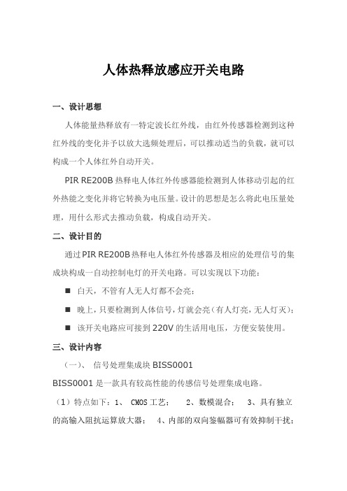
人体热释放感应开关电路一、设计思想人体能量热释放有一特定波长红外线,由红外传感器检测到这种红外线的变化并予以放大选频处理后,可以推动适当的负载,就可以构成一个人体红外自动开关。
PIR RE200B热释电人体红外传感器能检测到人体移动引起的红外热能之变化并将它转换为电压量。
设计的思想是怎么将此电压量处理,用什么形式去推动负载,构成自动开关。
二、设计目的通过PIR RE200B热释电人体红外传感器及相应的处理信号的集成块构成一自动控制电灯的开关电路。
可以实现以下功能:⏹白天,不管有人无人灯都不会亮;⏹晚上,只要检测到人体信号,灯就会亮(有人灯亮,无人灯灭);⏹该开关电路应可接到220V的生活用电压,方便安装使用。
三、设计内容(一)、信号处理集成块BISS0001BISS0001是一款具有较高性能的传感信号处理集成电路。
(1)特点如下:1、 CMOS工艺; 2、数模混合; 3、具有独立的高输入阻抗运算放大器; 4、内部的双向鉴幅器可有效抑制干扰;5、内设延迟时间定时器和封锁时间定时器;6、采用16脚DIP封装。
BISSOOO1管脚图(2)管脚说明1 A --可重复触发和不可重复触发选择端。
当A为“1”时,允许重复触发;反之,不可重复触发2 VO-- 控制信号输出端。
由VS的上跳变沿触发,使Vo输出从低电平跳变到高电平时视为有效触发。
在输出延迟时间Tx之外和无VS的上跳变时,Vo保持低电平状态。
3 RR1-- 输出延迟时间Tx的调节端4 RC1--输出延迟时间Tx的调节端5 RC2--触发封锁时间Ti的调节端6 RR2--触发封锁时间Ti的调节端7 VSS--工作电源负端8 VRFI --参考电压及复位输入端。
通常接VDD,当接“0”时可使定时器复位9VCI触发禁止端。
当Vc<VR时禁止触发;当Vc>VR 时允许触发(VR≈0.2VDD)10 IB--运算放大器偏置电流设置端11 VDD--工作电源正端12 2OUTO--第二级运算放大器的输出端13 2IN-I--第二级运算放大器的反相输入端14 1IN+I--第一级运算放大器的同相输入端15 1IN-I--第一级运算放大器的反相输入端16 1OUTO--第一级运算放大器的输出端(3)集成块内部结构图(4)工作原理BISS0001是由运算放大器、电压比较器、状态控制器、延迟时间定时器以及封锁时间定时器等构成的数模混合专用集成电路。
触摸延时开关的工作原理及电路图

触摸延时开关的工作原理及电路图一、工作原理触摸式延时开关有一个金属感应片在外面,人一触摸就产生一个信号触发三极管导通,对一个电容充电,电容形成一个电压维持一个场效应管管导通灯泡发光。
当把手拿开后,停止对电容充电,过一段时间电容放电完了,场效应管的栅极就成了低电势,进入截止状态,灯泡熄灭。
触摸式延时开关电路虚线右面是普通照明线路,左部是电子开关部分。
VD1~VD4、VS 组成开关的主回路,IC组成开关控制回路。
平时,VS处于关断状态,灯不亮。
VD1~VD4输出220V脉动直流电经R5限流,VD5稳压,C2滤波输出约12V左右的直流电供IC使用。
此时LED发光,指示开关位置,便于夜间寻找开关。
IC为双D触发器,只用其中一个D触发器将其接成单稳态电路,稳态时1脚输出低电平,VS关断。
当人手触摸一下电极M时,人体泄漏电流经R1、R2分压,其正半周使单稳态电路翻转,1脚输出高电平,经R4加到VS的门极,使VS开通,电灯点亮。
这时1脚输出高电平经R3向电容C1充电,使4脚电平逐渐升高直至暂态结束,电路翻回稳态,1脚突变为低电平,VS失去触发电压,交流电过零时即关断,电灯熄灭。
二、按钮触摸开关按动按钮开灯后,电路能自动延时关灯,电路如图二所示。
D1为开关所在的安装位置做指示,D2~D5组成桥式整流,将50Hz的的交流电整流为100Hz的脉动直流电压,按下K1,电流经过R3限流后通过D6为C1充电,同时V1的控制极得到触发电压,V1导通,灯泡点亮。
松手后K1自动复位断开,C1开始放电,为V1的控制极继续提供触发电压,V1继续导通,灯泡继续亮,当C1两端电压低于0.7V时,V1控制极失去有效的触发电压,此时V1阳极的脉动电流到0点时,与阴极电压相等而关断,灯泡熄灭,这就是单向可控硅的“过0关断”。
调整R2的阻值,使C1有效放电时间达到40~60秒钟最好。
图三电路多了一只用三极管组成的反相器,利用C1充电时间做灯泡点亮的延时时间。
自动空气开关的工作原理

自动空气开关的工作原理
自动空气开关是一种用于控制电气电路的开关装置,其工作原理可以描述如下。
当电流通过电路时,电路中的电流会通过电流保护装置。
在正常工作状态下,电流保护装置会保持闭合状态,维持电流的正常流动。
然而,当电路中出现过电流或短路情况时,电流保护装置会自动检测到异常,并迅速断开电路,从而阻断电流的进一步流动。
这是为了保护电器设备和避免火灾等事故的发生。
自动空气开关采用了电磁感应原理。
在正常情况下,电流通过电路时会在电流保护装置中产生磁场。
当电路中发生过电流或短路情况时,电路中的电流会急剧增大,导致保护装置中的磁场增强。
当电流保护装置中的磁场达到一定程度时,它会触发一个电磁脱扣机构,将电路迅速断开。
这种电磁脱扣机构可以通过弹簧或气体压力实现,从而确保断开电路的速度和可靠性。
在自动空气开关断开电路后,用户需要解决电路中的故障,并修复或更换相关设备,然后手动将自动空气开关复位,使其回到正常工作状态。
这样,自动空气开关通过检测和保护电路中的过电流和短路情况,确保电器设备和人身安全,防止由于电路故障导致的意外
事故发生。
同时,其快速断开电路的能力也可以最大程度地减小电流对电器设备的损害。
感应开关的分类和比较原理

感应开关的分类和比较原理感应开关是一种基于物理原理,利用感应效应将电磁信号转换为电信号的电器元件。
根据其工作方式和开关动作特点,感应开关可以分为多种类型。
常见的感应开关主要包括磁感应开关、光感应开关、声感应开关和温感应开关等。
下面将重点讨论这些感应开关的分类和比较原理。
1. 磁感应开关:磁感应开关是一种利用磁感应效应工作的开关。
它由磁场发生器和检测元件组成。
当探测物体接近磁感应开关时,物体的磁性体质或金属会影响到磁场,从而改变磁感应开关的输出电信号。
常见的磁感应开关有接近开关、磁保持开关和霍尔开关等。
磁感应开关广泛应用于安全门、电梯、楼宇照明等领域。
2. 光感应开关:光感应开关是一种利用光电效应感应光信号的开关。
它由光源、接受器和比较电路组成。
光感应开关通过发射光束,当有物体遮挡或反射光束时,光感应开关的接受器会将光信号转化为电信号,并通过比较电路产生开关信号。
光感应开关广泛应用于自动门、广告光箱、轨道交通等领域。
3. 声感应开关:声感应开关是一种利用声波的传播和接收来实现感应的开关。
它通常由声源、接受器和处理电路组成。
当有声源产生声波时,声感应开关的接受器可以捕捉到声波并转换为电信号,通过处理电路判断是否有物体接近,并产生相应的输出信号。
声感应开关常用于自动湿地刷洗器、语音报警装置等场所。
4. 温感应开关:温感应开关是一种利用温度的变化来控制开关动作的开关。
它通常由温度传感器和控制电路组成。
温感应开关通过感应环境温度的变化,从而控制开关的开闭。
常见的应用场景包括温控水龙头、恒温电炉等。
这几种感应开关的比较原理是根据不同的感应效应来实现对信号的转化和开关动作的触发。
一般来说,它们都是通过将感应信号转化为电信号,并通过处理电路产生开关信号。
其中,磁感应开关是利用物体的磁性质或金属对磁场的影响来触发开关动作;光感应开关是通过光束的阻碍或反射来触发开关动作;声感应开关则是通过声波的传播和接收来触发开关动作;而温感应开关则是通过感应环境温度的变化来触发开关动作。
电路中的开关控制电路通断的原理与应用
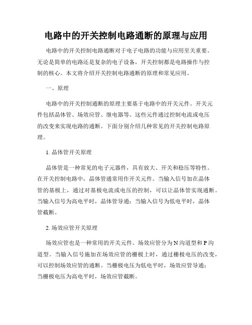
电路中的开关控制电路通断的原理与应用电路中的开关控制电路通断对于电子电路的功能与应用至关重要。
无论是简单的电路还是复杂的电子设备,开关控制都是电路操作与控制的核心。
本文将介绍开关控制电路通断的原理和常见应用。
一、原理电路中的开关控制通断的原理主要基于电路中的开关元件。
开关元件包括晶体管、场效应管、继电器等。
这些元件通过控制电流或电压的改变来实现电路的通断。
下面分别介绍几种常见的开关控制电路原理。
1. 晶体管开关原理晶体管是一种常见的电子元器件,具有放大、开关和稳压等特性。
在开关控制电路中,晶体管通常用作开关元件。
当输入信号加在晶体管的基极上,通过对基极电流或电压的控制,可以让晶体管实现通断。
当输入信号为高电平时,晶体管导通;当输入信号为低电平时,晶体管截断。
2. 场效应管开关原理场效应管也是一种常用的开关元件。
场效应管分为N沟道型和P沟道型。
当输入信号施加在场效应管的栅极上时,通过栅极电压的改变,可以控制场效应管的通断。
当栅极电压为低电平时,场效应管导通;当栅极电压为高电平时,场效应管截断。
3. 继电器开关原理继电器是一种电磁开关装置,通过控制电磁线圈的通断,来实现电路的开关控制。
继电器常用于大功率电路或需要隔离的场合。
当电磁线圈通电时,产生磁场使触点闭合;当电磁线圈断电时,磁场消失触点断开。
二、应用开关控制电路通断的原理应用广泛,下面介绍几个常见的应用领域。
1. 数字电子电路在数字电子电路中,开关控制电路通断用于实现逻辑门的功能。
逻辑门包括与门、或门、非门、与非门、或非门等。
通过将多个开关控制电路连接,可以实现复杂的逻辑运算。
2. 电源开关电源开关是开关控制电路在实际应用中的常见应用之一。
电源开关通常用于控制电路的通电与断电,以实现对电子设备的启动与关闭。
电源开关的稳定性和可靠性对于电子设备的正常运行至关重要。
3. 自动控制系统开关控制电路通断在自动控制系统中应用广泛。
比如自动灯光控制系统,通过在感应器检测到人体时控制开关电路的通断,实现灯光的自动开关。
基于单片机的红外感应自动门控制系统设计
┊┊┊┊┊┊┊┊┊┊┊┊┊装┊┊┊┊┊订┊┊┊┊┊线┊┊┊┊┊┊┊┊┊┊┊┊┊┊┊┊┊┊┊摘要随着社会的发展、科技的进步以及人们生活水平的逐步提高,各种方便于生活的自动控制系统开始进入了人们的生活,以单片机为核心的自动门系统就是其中之一。
本论文介绍的自动门控制器使用简单、工作稳定、成本低廉,采用双速运行、动作迅速。
除能实现自动开关门之外,还具有常开、常关、门禁、防误夹等多种功能。
通过对“控制自动门系统”的研究和设计,精心撰写了控制自动门系统论文。
本设计主要应用单片机8051作为控制核心,步进电机、热释电型红外传感器、电位器相结合的系统。
充分发挥了单片机的性能。
其优点硬件电路简单,软件功能完善,控制系统可靠,性价比较高等特点,具有一定的使用和参考价值。
单片机主要组成部分:中央处理器CPU(Central Processing Unit)、随机存储器RAM(Ramdom Access Memory)、只读存储器ROM(Read Only Memory)、中断系统、定时器/计数器以及I/O(Input/Output)口电路等部件。
单片机在控制领域的优点:体积小,成本低,运用灵活,易于产品化,它能方便的组成各种智能化的控制设备和仪器,做到机电一体化。
它能针对性的解决从简单到复杂的各类控制任务,抗干扰能力强,适用温度范围宽,可以方便的实现多机和分布式控制,使整个控制系统的效率和可靠性大为提高。
本课题通过红外传感器感应到来人进出门时向单片机送入一个高电平,后以单片机为控制核心对步进电机进行控制。
系统实现简单,但功能强,能有效的对门进行开关控制。
关键词:单片机,自动门,直流电机,红外传感器 ,转速测量┊┊┊┊┊┊┊┊┊┊┊┊┊装┊┊┊┊┊订┊┊┊┊┊线┊┊┊┊┊┊┊┊┊┊┊┊┊┊┊┊┊┊┊AbstractAs it becomes more and more automatic and informational nowadays, the application of microcontroller also becomes more and more extensively. Progress of with the development of the society, science and technology and gradual improvement of people's living standard, various kinds of help automatic control system in life begin to enter people's life, the system of automatically-controll door taking one-chip computer as the core is one of them. Indicate too that the automatic controlled field became a member in digitized era at the same time. Its practicability is strong, multiple functional, modern techniques, make people believe this is an achievement of scientific and technological progress. It lets the mankind understand even more, the development in digital era will change human’s life, will quicken the development of science and technology.Through the research and design to the thing that "the system of single chip controlled auto-door", I have written the computer and controlled the systematic thesis of automatically controlled door meticulously. Thesis this is it rely mainly on one-chip computer to explain emphatically, DC motor and the measure of rotate speed central systems.It is uses 8051 as core of controlling, the DC motor, infrared sensor and electromagnetic switch combine together mainly to design originally. Give full play to the performance of the one-chip computer. Its advantage hardware circuit is simple, the software is with perfect function, the control system is reliable, higher characteristic of the sex price, and it has certain use and reference value.Keywords : Microcontroller Auto-door DC motor Infrared sensor Rotate speed- measure┊┊┊┊┊┊┊┊┊┊┊┊┊装┊┊┊┊┊订┊┊┊┊┊线┊┊┊┊┊┊┊┊┊┊┊┊┊┊┊┊┊┊┊目录第1章课题研究的意义和目的 (5)第2章课题的功能概述 (6)第3章数字控制开关电源的设计 (7)3.1 总体设计方案 (7)3.2系统设计 (7)3.3基本设计电路 (7)3.4电路设计 (8)3.4.1 数字调压控制电路 (10)3.4.2 计数控制电路 (10)3.4.3 数模转换电路 (10)3.4.4 比较器及PNM控制电路 (11)3.4.5 输出稳压电路 (12)第4章单片机的介绍和发展概况 (13)第5章单片机的工作原理 (14)5.1单片机的基本组成 (14)5.2 MCS-51的寻址方式 (15)5.3指令 (15)5.4计数初值的计算 (15)5.4.1计数的工作方式 (16)5.4.2定时的工作方式 (16)5.5中断响应的条件 (17)5.6串行口工作方式及帧格式 (17)第6章步进电机的发展和应用 (18)第7章步进电机的工作原理 (21)第8章用单片机和CPLD实现步进电机的控制 (23)8.1 电机控制电路设计 (23)8.2 步进电机控制方案 (26)8.3 电机驱动器硬件结构 (27)8.4 CPLD硬件电路设计 (27)8.5 控制的实现 (28)第9章红外热释电处理芯片BISS0001 (31)第10章红外接收和电机驱动电路配制方案 (35)┊┊┊┊┊┊┊┊┊┊┊┊┊装┊┊┊┊┊订┊┊┊┊┊线┊┊┊┊┊┊┊┊┊┊┊┊┊┊┊┊┊┊┊10.1 开门信号 (37)10.2 门禁系统与非公共区域的自动门 (37)10.3 解锁动作与开门动作之间的协调 (38)10.4 集中控制 (38)第11章逻辑运算电路设计 (39)第12章软件设计 (40)第13章其他问题 (41)参考文献 (42)结束语 (43)致谢 (44)附录 (45)┊┊┊┊┊┊┊┊┊┊┊┊┊装┊┊┊┊┊订┊┊┊┊┊线┊┊┊┊┊┊┊┊┊┊┊┊┊┊┊┊┊┊┊第1章课题研究的意义和目的自动门根据使用的场合及功能的不同可分为自动平移门、自动平开门、自动旋转门、自动圆弧门和自动折叠门等,其中平开门用的场合较少,旋转门由于昂贵而且非常庞大,一般只用于有需要的高档宾馆,自动平移门使用得最广泛,大家一般所说的自动门和感应门就是指自动平移门。
ttp223触摸开关电路图
特性描述:2.5V〜5V宽电压范围,3ua〜5ua超低工作电流SOT23-6封装是业内最小的,易于设计外围仅需要一个CS电容器,因此设计简单感应距离大于5cm,可以通过更改CS电容参数来调整感应距离多种输出模式是可选的Qt100可以部分替换且成本低强大的抗干扰能力,无误触发ttp223触摸开关的电路图(1)2.5V〜5V宽电压范围,3ua〜5ua超低电流。
SOT23-6封装是业界最小的,易于设计。
外围仅需要一个CS电容器,因此设计简单。
感应距离大于5cm,可以通过更改CS电容的参数来调整感应距离。
多种输出模式是可选的。
Qt100可以部分替换,成本低。
具有很强的抗干扰能力,不会被错误触发。
ttp223触摸开关的电路图(2)Ttp223是一种通常用于触摸台灯的微功耗CMOS触摸IC。
它的最大工作电压为5.5V,静态功耗仅为几微安。
在上面的电路中,只要您触摸触摸电极,IC的输出就会输出高电平控制信号。
如果再次触摸它,输出将变为低电平。
触摸台灯是利用IC输出的控制信号通过三极管来控制LED灯珠,从而实现触摸开关控制。
包含原理图和PCB工程文件界面设计说明:电源连接5V电源;如果是数字信号,则最好连接J1接口的5和6引脚,即网络标签为d0和D1的接口。
如果是模拟信号,则只能连接到J1接口的引脚5和6,即标记为d0和D1的接口;如果是IIC接口信号,则只能连接J1接口的1和2引脚,即以Ad5 / SCL和Ad4 / SDA 作为网络标签的接口;如果模块板上的数字接口多于两个,即J1接口的5和6引脚不够用,请继续使用J1接口的1和2引脚。
P11跳线接口说明:1. Tog 0,alhb 0,直接模式,Q高电平有效2. Tog 0,alhb 1,直接模式,Q低电平有效3. Tog 1,alhb 0,锁存输出,通电状态= 04. Tog 1,Alhb 1,锁存输出,通电状态= 10.jpgAltium Designer绘制的ttp223金属触摸开关的原理图和PCB图如下:(51hei附件可以下载工程文件)0.png 0.png触摸传感器是基于电容感应原理的触摸开关模块。
红外感应灯电路设计及原理
红外感应灯电路设计及原理1、电路主要光学元件(1)光敏电阻的应用光敏电阻又称光导管, 它几乎都是用半导体材料制成的光电器件。
光敏电阻没有极性, 是一个电阻器件。
制作光敏电阻的材料一般是金属硫化物和金属硒化物,通常采用涂敷、喷涂等方法,在陶瓷基片上涂上半导体薄膜,经烧结而成。
光敏电阻的结构:在底板上均匀地涂上一层薄薄的半导体物质,称为光导层。
半导体的两端装有金属电极与引出线端相连接,通过引出线端接入电路。
为了防止周围介质的影响,在半导体光敏层上覆盖了一层漆膜,漆膜的成分应使它在光敏层最敏感的波长范围内透射率最大。
为了提高灵敏度,光敏电阻的电极一般采用梳状图案,光敏电阻结构,光敏电阻电极,光敏电阻接线图光敏电阻工作原理--内光电效应。
光照射到本征半导体上,材料中的价带电子吸收了光子能量跃迁到导带,激发出电子、空穴对,增强了导电性能,使阻值降低。
光照停止,电子空穴对又复合,阻值恢复。
亮电阻很小,暗电阻很大。
要使价带电电子跃迁到导带,入射光子的能量满足刚好发生内光电效应的临界波长。
常用的光敏电阻器是硫化镉光敏电阻器,它是由半导体材料制成的。
光敏电阻器的阻值随入射光线(可见光)的强弱变化而变化,在黑暗条件下,它的阻值(暗阻)可达1-10MΩ;在强光条件(100LX)下,它阻值(亮阻)仅有几百至数千欧姆。
光敏电阻器对光的敏感性(即光谱特性)与人眼对可见光(0.4-0.76um)的响应很接近,只要人眼可感受的光,都会引起它的阻值变化。
本电路采用MG42型CdS光敏电阻,CdS光敏电阻属半导体光敏器件,产品经受强化老练实验,除具有灵敏度高,反应速度快,光谱特性好等特点外,在高温、多湿的恶劣环境下,仍能保持其高度的稳定性和可靠性,适合于将其用于各种环境,MG42型光敏电阻与其它型号相比具有:工作电压和额定功率比较低的特点,其亮、暗电阻也适合于本照明电路的需要,所以在设计时选择了这个型号。
(2)可控硅元件的工作原理可控硅是P1N1P2N2四层三端结构元件,共有三个PN结,分析原理时,可以把它看作由一个PNP管和一个NPN管所组成,其等效图解如图1所示图1可控硅等效图解图当阳极A加上正向电压时,BG1和BG2管均处于放大状态。
如何设计电容感应式触摸开关
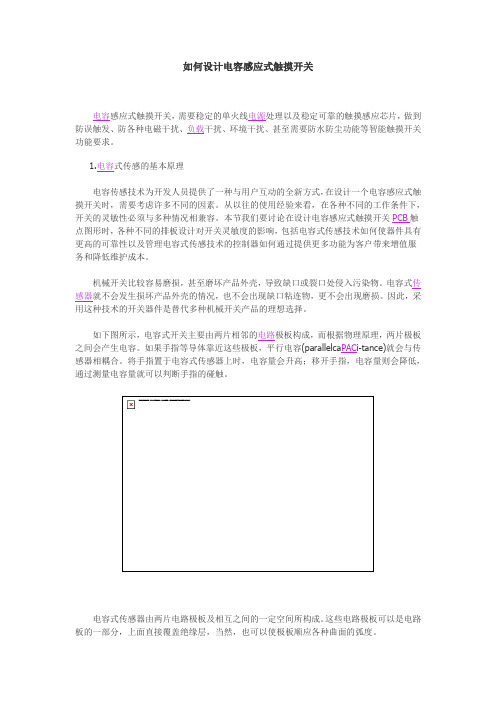
如何设计电容感应式触摸开关电容感应式触摸开关,需要稳定的单火线电源处理以及稳定可靠的触摸感应芯片,做到防误触发、防各种电磁干扰、负载干扰、环境干扰、甚至需要防水防尘功能等智能触摸开关功能要求。
1.电容式传感的基本原理电容传感技术为开发人员提供了一种与用户互动的全新方式,在设计一个电容感应式触摸开关时,需要考虑许多不同的因素。
从以往的使用经验来看,在各种不同的工作条件下,开关的灵敏性必须与多种情况相兼容。
本节我们要讨论在设计电容感应式触摸开关PCB触点图形时,各种不同的排板设计对开关灵敏度的影响,包括电容式传感技术如何使器件具有更高的可靠性以及管理电容式传感技术的控制器如何通过提供更多功能为客户带来增值服务和降低维护成本。
机械开关比较容易磨损,甚至磨坏产品外壳,导致缺口或裂口处侵入污染物。
电容式传感器就不会发生损坏产品外壳的情况,也不会出现缺口粘连物,更不会出现磨损。
因此,采用这种技术的开关器件是替代多种机械开关产品的理想选择。
如下图所示,电容式开关主要由两片相邻的电路极板构成,而根据物理原理,两片极板之间会产生电容。
如果手指等导体靠近这些极板,平行电容(parallelca PAC i-tance)就会与传感器相耦合。
将手指置于电容式传感器上时,电容量会升高;移开手指,电容量则会降低,通过测量电容量就可以判断手指的碰触。
电容式传感器由两片电路极板及相互之间的一定空间所构成。
这些电路极板可以是电路板的一部分,上面直接覆盖绝缘层,当然,也可以使极板顺应各种曲面的弧度。
构建电容式开关的要素包括:电容器、电容测量电路系统、从电容值转换成感应状态的局部智能装置。
典型的电容式传感器电容值介于10~30pF之间。
通常来说,手指经由Imm绝缘层接触到传感器所形成的耦合电容介于1~2pF的范围。
越厚的绝缘层所产生的耦合电容愈低。
若要传感手指的触碰,必须实现能够检测到1%以下电容变化的电容传感电路。
增量求和调制器是一种用于测量电容的高效、简单的电路,下图给出了典型的拓扑结构。
六款简单的开关电源电路设计,内附原理图详解
六款简单的开关电源电路设计,内附原理图详解简单的开关电源电路图(一)简单实用的开关电源电路图调整C3和R5使振荡频率在30KHz-45KHz。
输出电压需要稳压。
输出电流可以达到500mA.有效功率8W、效率87%。
其他没有要求就可以正常工作。
简单的开关电源电路图(二)24V开关电源,是高频逆变开关电源中的一个种类。
通过电路控制开关管进行高速的道通与截止,将直流电转化为高频率的交流电提供给变压器进行变压,从而产生所需要的一组或多组电压!24V开关电源的工作原理是:1.交流电源输入经整流滤波成直流;2.通过高频PWM(脉冲宽度调制)信号控制开关管,将那个直流加到开关变压器初级上;3.开关变压器次级感应出高频电压,经整流滤波供给负载;4.输出部分通过一定的电路反馈给控制电路,控制PWM占空比,以达到稳定输出的目的。
24v开关电源电路图简单的开关电源电路图(三)单端正激式开关电源的典型电路如下图所示。
这种电路在形式上与单端反激式电路相似,但工作情形不同。
当开关管VT1导通时,VD2也导通,这时电网向负载传送能量,滤波电感L储存能量;当开关管VT1截止时,电感L通过续流二极管VD3 继续向负载释放能量。
在电路中还设有钳位线圈与二极管VD2,它可以将开关管VT1的最高电压限制在两倍电源电压之间。
为满足磁芯复位条件,即磁通建立和复位时间应相等,所以电路中脉冲的占空比不能大于50%。
由于这种电路在开关管VT1导通时,通过变压器向负载传送能量,所以输出功率范围大,可输出50-200 W的功率。
电路使用的变压器结构复杂,体积也较大,正因为这个原因,这种电路的实际应用较少。
简单的开关电源电路图(四)推挽式开关电源的典型电路如图六所示。
它属于双端式变换电路,高频变压器的磁芯工作在磁滞回线的两侧。
电路使用两个开关管VT1和VT2,两个开关管在外激励方波信号的控制下交替的导通与截止,在变压器T次级统组得到方波电压,经整流滤波变为所需要的直流电压。
电感接近开关课程设计

电感接近开关课程设计一、课程目标知识目标:1. 学生能理解电感接近开关的工作原理,掌握其电路组成和功能。
2. 学生能描述电感接近开关在工业自动化控制中的应用,了解其优点和局限性。
3. 学生掌握电感接近开关的选型和使用方法,能够根据实际需求选择合适的电感接近开关。
技能目标:1. 学生能够运用所学知识,正确连接和调试电感接近开关电路。
2. 学生能够分析和解决电感接近开关在实际应用中出现的问题。
3. 学生能够运用电感接近开关设计简单的自动化控制电路。
情感态度价值观目标:1. 学生通过学习电感接近开关,培养对电子技术的兴趣,增强科技创新意识。
2. 学生在学习过程中,学会与他人合作,培养团队精神和沟通能力。
3. 学生认识到电感接近开关在工业生产中的重要性,增强社会责任感和使命感。
课程性质分析:本课程为电子技术应用课程,旨在让学生了解电感接近开关的工作原理和应用,提高学生的实际操作能力和解决问题的能力。
学生特点分析:学生为初中年级,具备一定的电子技术基础,好奇心强,喜欢动手操作,但理论知识掌握程度有限。
教学要求:1. 注重理论与实践相结合,提高学生的实际操作能力。
2. 通过小组合作,培养学生的团队协作能力和沟通能力。
3. 关注学生的个体差异,因材施教,使每个学生都能达到课程目标。
二、教学内容1. 电感接近开关的工作原理及特性- 电磁感应原理介绍- 电感接近开关的电路组成与功能- 电感接近开关的静态和动态特性分析2. 电感接近开关的应用领域- 工业自动化控制中的典型应用案例- 电感接近开关在日常生活和其他领域的应用3. 电感接近开关的选型与使用- 不同类型电感接近开关的参数对比- 选型依据:检测距离、检测物体、环境条件等- 电感接近开关的安装、调试与维护方法4. 实践操作与案例分析- 设计简单电感接近开关控制电路- 实际操作:连接、调试电感接近开关- 分析常见故障与解决方法5. 教学内容的安排与进度- 第一课时:电感接近开关工作原理及特性- 第二课时:电感接近开关的应用领域与选型- 第三课时:实践操作与案例分析教学内容关联教材章节:- 《电子技术基础》第四章:电磁感应与电感元件- 《自动化控制技术》第三章:传感器及其应用教学内容注重科学性和系统性,结合课程目标,使学生掌握电感接近开关的基础知识,培养实际操作能力,提高解决问题的技巧。
中频感应电源的设计说明书
关键词:感应加热电源;串联谐振;逆变电路;IGBT
Abstract
The Intermediate Frequency Induction Heating has been widely applied in melting, casting, bend, hot forging, welding, Surface Heat Treatment due to its advantages of high heating efficiency、high speed、easily controlled、easily being mechanized and automated.
有效值为:
(1-3)
感应电势E在工件中产生感应电流 使工件内部开始加热,其焦耳热为:
(1-4)
式中: ——感应电流有效值(安),R——工件电阻(欧),t——时间(秒)。
这就是感应加热的原理。感应加热与其它的加热方式,如燃气加热,电阻炉加热等不同,它把电能直接送工件内部变成热能,将工件加热。而其他的加热方式是先加热工件表面,然后把热再传导加热内部。
车门感应开关原理
车门感应开关原理车门感应开关原理车门感应开关是一种在汽车中广泛使用的电子装置。
它是由传感器、控制电路和电源组成的系统。
传感器通过进行信号变化,将车门打开或关闭的信号传递给控制电路,由控制电路对车门进行控制。
1、传感器车门感应开关中的传感器采用了电磁感应原理,它通过一个铁芯线圈和一个变化的磁场来检测车门的开闭状态。
当车门关闭时,传感器的铁芯线圈上方的磁场被截断,线圈中的电流就会发生变化。
这个变化的电流就被传送到控制电路中,让它知道车门已经关闭。
同样的,当车门打开时,传感器也通过检测到变化的电流来确定车门的状态。
2、控制电路控制电路是车门感应开关的核心部分,它负责处理传感器中的信号,并将信号转换为可控制车门的信号。
控制电路会通过将电流传递到车门锁定机构、电动车窗机构或其他相关系统来控制车门的打开或关闭。
3、电源车门感应开关需要一个可靠的电源来工作。
这个电源必须能够在汽车工作时保证始终供电,以确保车门感应开关能够正常工作。
这个电源的类型通常是车辆电池,但也可以是其他类型的电池或电源。
车门感应开关是一种在汽车中广泛使用的电子装置,它通过传感器、控制电路和电源组成的系统来控制车门的打开和关闭。
通过了解车门感应开关的原理,可以更好地理解它的工作原理,从而更好地维护和保养汽车。
车门感应开关在汽车行业中的应用非常广泛,其主要作用是避免车门被意外打开,保障车内乘客的安全。
在使用车门感应开关时,由于传感器的信号检测精度较高,操作较为简单,因此其使用非常便捷。
车门感应开关也可根据不同车型进行适当的调整,以实现更精细的控制操作。
车门感应开关还具备以下几个优点。
1、安全性高由于车门感应开关能够准确地检测车门的状态,例如车门的开关状态、车门的锁定状态等等。
可以避免车门因用户操作不当或遭受外力撞击而突然打开,从而防止车内乘客受到意外伤害。
2、操作简单车门感应开关的使用相当便捷,并且其操作方式非常简单。
唯一需要注意的是,车门感应开关的使用需要在电池正常工作的情况下进行。
自动感应门的基本工作原理

自动门感应门的基本工作原理自动门机的基本组成大体上相同,有了以上构成,再加上开门信号,就可以配置成一套简单的自动门系统了;自动门的系统配置是指根据使用要求而配备的,与自动门控制器相连的外围辅助控制装置,如开门信号源、门禁系统、安全装置、集中控制等;必须根据建筑物的使用特点;通过人员的组成,楼宇自控的系统要求等合理配备辅助控制装置;1、开门信号自动门的开门信号是触点信号,微波雷达和红外传感器是常用的两种信号源:微波雷达是对物体的位移反应,因而反应速度快,适用于行走速度正常的人员通过的场所,它的特点是一旦在门附近的人员不想出门而静止不动后,雷达便不再反应,自动门就会关闭,对门机有一定的保护作用;红外传感器对物体存在进行反应,不管人员移动与否,只要处于传感器的扫描范围内,它都会反应即传出触点信号;缺点是红外传感器的反应速度较慢,适用于有行动迟缓的人员出入的场所;另外,如果自动门接受触点信号时间过长,控制器会认为信号输入系统出现障碍;而且自动平移门如果保持开启时间过长,也会对电气部件产生损害;由于微波雷达和红外传感器并不了解接近自动门的人是否真要进门,所以有些场合更愿意使用按键开关;按键开关可以是一个触点式的按钮,更方便的是所谓肘触开关;肘触开关很耐用,特别是它可以用胳膊肘来操作;避免了手的接触;还有脚踏开关,功能一样,但对防水的要求较高,而且脚踏的力量很大,容易使脚踏开关失效;还有一种带触点开关的拉手,当拉手被推或在反方向拉到位时,向门机提供触点信号;现在的楼宇自控有时会提出特殊的要求,例如使用电话的某一分线控制开门;要达到这个要求,只要保证信号是无源的触点信号即可;有些情况下,人们会提出天线遥控的要求;用一个无线接受器与自动门进行触点式连接,再配一个无线发射器,就可以达到要求;不过,现在的无线电波源太多,容易导致偶然开门是一个麻烦的问题;定时器可以自动控制门的状态,其原理是将时钟与特定的开关电路相连,可预设定时间将自动门处于自动开启或锁门状态;2、门禁系统与非公共区域的自动门如果说对自动门的性能和质量要求最高的,是在使用频率极高的大型公共区域,那么自动门功能要求最高是对进出人员进行选择的非公共区域;门禁系统是对入门授权的识别;在识别或检测入门授权通过以后,向自动门的控制系统提供开门信号;在提供开门信号之前,自动门必须处于锁门的状态;门禁系统包括从最简单的钥匙开关,密码锁,磁卡锁;考勤统计系统;一直到复杂的体重识别系统,指纹识别系统等;但无论系统怎样复杂,最终都是给自动门提供开门的触点信号;信号电路的屏蔽对避免由于无关信号的干扰而误开门的情况发生非常重要;3、对自动门的要求就是解锁动作与开门动作之间的协调;应用于自动平移门的电子锁有锁皮带的电磁锁和锁门体吊挂件的电动锁,锁电机的三种;后者用于重型自动平移门,自动平开门的电子锁有电磁门吸,电子插销锁和电子开门器,电子开门的作用力方向不影响门的开启动作,不易发生误操作;还有一种带触点开关的机械锁,使锁与开关结合,锁不处于开锁状态,触点就不能接触,不可能发生误操作;4、集中控制集中控制的概念,包括集中监视自动门运行状态和集中操作多个自动门两层含义,集中监视自动门开门关门状态可以通过位置信号输出电路来实现,可以采用接触式开关,当门到达一定位置如开启位置时,触动开关而给出触点信号;也可以采用感应式信号发生装置,当感应器探测到门处于某一位置时发出信号;在中控室设置相应的指示灯,就可以显示自动门的状态,而集中操作通常指同时将多个门打开或锁住,这取决于自动门控制器上有无相应的接线端子;郑州同创自动门工程有限公司,是专门从事旋转门,自动门,玻璃门-淄博肯德基门等门业产品的研究、开发、生产制造、设计、安装及售后服务于一体的专业化公司;目前,公司推出“卓凡”系列旋转门,不仅在质量上可与其他着名品牌相媲美;而且在功能上体现“以人为本”的原则;公司拥有一批专业经验的技术人员以保证客户的需求;并凭借精湛的专业生产技术,可靠的产品质量,优惠的价格受到新老客户的一致好评;公司聚集了大量多年从事本行业的技术专业人才,为酒店、宾馆、银行、商场、写字楼、医院、机场、企事业单位提供专业的设计、安装及售后服务于一体的全方位服务;已于多家国内知名装饰公司建立长期合作关系; 公司目前生产的主要产品有大型豪华二翼自动旋转门,自动、手动、三四翼旋转门;水晶旋转门、弧形门、自动平滑门以及各类异型门等系列产品,在用户中赢得了广泛好评及信赖,树立了良好的企业形象; 公司“以质量求生存,以信誉求发展”作为卓凡人不断努力的发展方向;为广大用户提供最完善的技术、最优质的产品和最人性化的服务;致力打造中国门业永恒品牌; 企业使命:创造完美门庭和高雅环境企业精神:诚信、和谐、创新、发展经营理念:以人为本,科技兴业设计理念:智能化、安全化、人性化质量方针:注重细节、持续改进、追求卓越服务理念:每个工程,都视为一件作品;每个工程,都做到“量体裁衣“;每个工程,都做是成放心工程; 团队精神:服从、合作、沟通、整合代表人物风格:创新、守信、勤奋、执着企业宣传标语:卓凡,让世界旋转起来。
- 1、下载文档前请自行甄别文档内容的完整性,平台不提供额外的编辑、内容补充、找答案等附加服务。
- 2、"仅部分预览"的文档,不可在线预览部分如存在完整性等问题,可反馈申请退款(可完整预览的文档不适用该条件!)。
- 3、如文档侵犯您的权益,请联系客服反馈,我们会尽快为您处理(人工客服工作时间:9:00-18:30)。
自动感应开关电路设计摘要随着现代通信技术的飞速发展,已经提出了更高的要求,通信电源的可靠性,重量,体积,效率等。
相移和在直流/直流电压和电流全桥变换器结构简单的高功率应用中,输出功率大,效率高,易于实现软开关,具有一系列优点受到功率开关管,如小力,对它的研究具有非常重要的意义。
首先,DC / DC升压转换器的电流触发电路,输入电路,反馈电路的控制芯片,详细的推挽式变压器,损耗问题进行了研究和分析的MOS场效应晶体管的焦点。
其次,本文还简单介绍了在本实验所使用的设备的设备所必需的参数,建立了模型,用Protel Altium Designer 6.9仿真软件系统的稳定性进行了分析。
最后的仿真结果,根据自己的实际电路,从而使调试一切正常,达到了预期的效果。
关键词:DC/DC电压变换器;推挽变压器;反馈电路控制芯片AbstractWith the rapid development of modern communication technology, higher requirements have been put forward, communication power supply reliability, weight, volume, efficiency etc.. The phase shift and the application in high power DC / DC voltage and current structure of full bridge converter is simple, high output power, high efficiency, easy to realize soft switching, has a series of advantages by the power switch, such as small capacity, it is very important to research on it. First of all, the current DC / DC converter trigger circuit, input circuit, feedback control circuit, push-pull transformer in detail, loss of focus of MOS field effect transistor research and analysis. Secondl. Secondly, the paper simply introduces the parameters required in the use of the experimental equipment, established the model for stability, Protel Altium Designer 6.9 simulation software system is analyzed in the paper. Finally the simulation results. Finally the simulation results, according to the actual circuit of their own, so that all the normal debugging, achieves the expected effect.Keywords: DC/DC boost converter; push-pull transformer; feedback circuit control chip目录摘要 (I)1 绪论 (1)1.1开关电源的发展历程 (1)1.2开关电源的分类 (1)1.2.1按驱动方式分类 (1)1.2.2按能量转换过程的类型分类 (2)1.2.3按输入与输出是否隔离分类 (2)1.2.4按功率开关管关断和开通工作条件分类 (2)1.3开关电源的特点 (3)2 开关电源主电路的设计 (4)2.1逆变器的工作原理 (4)2.2换器的滤波电容和电感的选取.................................................... 错误!未定义书签。
2.2.1滤波电容的选取.................................................................. 错误!未定义书签。
2.2.2滤波电感的选取.................................................................. 错误!未定义书签。
2.2.3高频逆变电源的设计核心就是变压器的设计.................. 错误!未定义书签。
2.3变压器绕制步骤 (5)2.4硬件抗干扰措施 (6)2.5仿真结果 (6)3 开关电源控制芯片的设计 (8)3.1 TL494芯片简介 (8)3.2外围电路的介绍 (13)3.3仿真结果 (14)4 开关电源反溃电路的设计 (15)4.1电源反馈部分的工作原理 (15)4.2仿真结果 (17)结论 ............................................................................................ 错误!未定义书签。
致谢......................................................................................................... 错误!未定义书签。
参考文献. (21)1 绪论1.1开关电源的发展历程随着电子技术的发展,直流/直流电源已经成为一个巨大的产业,不断改进材料,工艺,包装,使直流/直流产品一般由行业使用,快速促进在军事,医疗,航空航天等领域。
我们有许多的直流/直流电源公司生产的数千万美元的产值,从0.5瓦一千瓦的产品。
从单输出到多个输出。
一些公司有他们自己的DC/DC模块的产品组合设计电力系统用户的需求。
激烈的竞争形势,导致厂家积极采用先进技术,使模块具有最小的体积达到最大功率输出,一些新产品的功率密度已达10瓦每立方英寸。
为了提高效率和输出功率是我们追求的目标,肖特基整流器和磁性材料具有改进的开关场效应晶体管,,是一个关键因素。
计算机工业的发展提出了新的目标,直流/直流电源。
TTL逻辑电路电压在5V,超大规模集成电路的驱动电流大,5A电流设计至少25瓦的输出功率模块。
节约能源,新的CMOS集成电路设计的3.3V电压降,也需要5A电流仅能使用16.5瓦的模块。
目前,一些超大规模集成电路制造商在电压低于2.9V感兴趣,2.1 V,以节省电力,由于直流/直流电源产品带来了新的挑战。
直流/直流模块采用同步整流技术在一定程度上的设计,提高了工作效率,但最终的改善是依赖于半导体器件性能的改善。
为控制电路解决直流/直流模块。
使用一个一定规模的集成电路将直流/直流模块的性能是革命性的进步[ 1 ]。
外部直流/直流模块的散热是一个关键问题。
由于尺寸的限制,模块的情况下必须有良好的导热性,否则会在半导体元件烧坏。
近年来,电路印刷在铝或陶瓷村板直流/直流产品世界。
铝和陶瓷板的导热性较好,为发展DC/DC模块提供了一个新的方向。
1.2开关电源的分类1.2.1按驱动方式分类1)自激式开关电源开关管起着振荡器器件和功率开关的作用。
2)他激式开关电源备有专门独立的振荡电路,使用专用的脉冲调宽控制器PWM芯片就是中一例。
1.2.2按能量转换过程的类型分类1)直流—直流(DC-DC)变换器它是将一种直流电转换成另一种或几种直流电。
DC-DC变换器是直流开关电源的核心部件,也是非隔离式或隔离式变换器直流电源的重要组成部分。
2)逆变器(DC-AC)它是将直流电转换交流电的开关变换器,是交流输出开关电源和不间断电源(UPS)的主要部件。
3)开关整流器(AC-DC)它是将交流电转换成直流电能的一种电源装置,这种变换器其变换过程应该理解为交流-直流-交流-直流(AC-DC-AC-DC)。
4)交流-交流变换器(AC-AC)它是将一种频率的交流电直接转换成另一种恒频或可变频率的交流电,或是将交流电直接转换成恒频交流电的变换装置。
1.2.3按输入与输出是否隔离分类1)隔离式开关变换器的高频变压器将侧转换器(输入)和两个侧(输出)隔离。
转换器的结构主要有单端正激,反激式转换器,中心抽头(推挽)转换器,半桥转换器,全桥变换器。
2)非隔离式开关变换器在电气和非隔离输入输出。
输入和输出共享一个公共端。
转换器的结构主要有降压(降压)转换器,升压(升压)转换器,降压-升压(升压)变换器以及它们的组合变形等电路,Cuk转换器,Zeta转换器,SEPIC转换器1.2.4按功率开关管关断和开通工作条件分类1)硬开关变换器功率开关器件接通或断开电压或电流应力条件下。
这不仅产生的开关损耗,开关尖峰形成干涉噪声,需要额外的屏蔽,抗噪声滤波,以满足高精度的要求,高性能的电动设备。
2)软开关变换器功率开关器件承受的电压或电流不受力情况或关闭;或是加入到高压开关管零,称为零电压开关(ZVS);或电流通过开关管的零,称为零电流开关(ZCS)。
因为没有电压开关过程中,电流的重叠(理想的),大大降低开关损耗和开关电压,噪声小,开关变换器的高频,小型化。
1.3开关电源的特点直流/直流电源应用于70年代,形成了一个模块化的产品。
由于直流/直流电路设计相对简单,成本低,好的设计可以快速解决复杂的问题,设计,测试,生产标准,已形成了一套完整的直流/直流电源。
这大大简化了电子设计的过程中,电气设备系统。
在大型设备(如程控交换机),往往约占系统成本的20%,电源的设计考虑,并不是因为整个系统断电工作不正常。
直流/直流电源模式是最简单和最方便的方法。
在系统设计的早期阶段,然后根据内部的所有电路的电压和电流不同系统的要求,根据DC/DC模块制造商的产品目录以找到合适的直流江吴模块产品。
这样的系统在直流/直流模块有特殊要求,也可以是直流/直流两个模块制造商的特殊设计和生产。
因此,设计师用更少的能源为动力,把主要精力投入到设计系统。
直流/直流电源模块,可以使这一切成为可能。
随着小型化功率模块可以大大简化设备结构,减小体积重量,同时,高可靠性的专用电源模块,可以大大提高整个系统的可靠性,更有利于降低设计成本和设备成本。
2 开关电源主电路的设计2.1逆变器的工作原理图2-1 直流逆变推挽式结构图2-2给出了推挽逆变-高频变压-全桥整流DC/DC变换器的基本电路拓扑。