安德兹RF100系列变频器说明书
Godrive100说明书
1.1 安全信息定义 ......................................................................................................... 2 1.2 警告标识................................................................................................................ 2 1.3 安全指导................................................................................................................ 2 2 产品简介 ........................................................................................................................ 4 2.1 快速启动...........................................
Lift使用说明
否则可能引起火灾、事故
y FRENIC-Lift 不可用于生命维持装置等与人体事故直接相关的用途。 y 本产品是在严格的质量管理监督下生产的,将其适用于可能因偶发的故障而导致重大事故或损失的设备时,请设
置安全装置。
否则可能引发事故
i
关于安装
危险
y 请安装在金属等不可燃物上。 y 请不要安装在可燃物附近。
富士电机机器制御株式会社
INR-SI47-1037 b- CW
Copyright © 2005-2006 Fuji Electric FA Components & Systems Co., Ltd. All rights reserved.
本操作说明书的著作权归富士电机机器制御株式会社所有。 本书中记载的公司名称和产品名称一般是各公司的商标或注册商标。 有时会在没有预告的情况下对规格进行变更。
前言
非常感谢您选购本公司的通用变频器 "FRENIC-Lift" 系列。本产品是可使 3 相异步电动机(以下为异步电动机) 及永磁同步电动机进行可变速运转的装置,为上下搬运装置专用变频器。
使用前,请仔细阅读本操作说明书,并正确使用。错误的操作,会妨碍正常的运转,并导致寿命降低和引起故障。 所控制的电动机为同步电动机的情况下,需要符合脉冲编码器规格的 PG 接口卡(选配件)。请阅读 PG 接口卡(选 配件)操作说明书。
否则可能引起火灾、事故
y 一般情况下控制信号线的被覆未经过强化绝缘处理,因此一旦控制信号线与主电路带电部分直接接触,可能会因
某些原因而导致绝缘层破坏。这种情况下,会引起主电路高电压被施加到控制信号线上的危险性,因此请注意不 要使控制信号线接触到主电路带电部分。 否则可能引发事故、触电
fz100变频器说明书
fz100变频器说明书
感谢您选用Fz100系列高性能通用型变频器。
本手册为您提供变频器的安装、配线、功能参设定、日常维护、故障诊断与排除等相关细则及注意事项。
为了充分发挥产品的功能并确保使用者和设备的安全,在使用变通器之前,请您务必详细阅读本手册。
不正确的使用可能会造成变频器运行异常、发生故障、降低使用寿命,乃至发生设备损坏、人身伤亡等事故!
以下各事项请使用者在操作本产品时特别留意实施配线,务必关闭电源。
变频器务必正确的按。
交流电源线绝不可接至变频器输出端于U V W变系器内部有高压电路部分,严禁用手触摸机内部件。
只有合格的电专业人员才可以安装、配线及修理保养变频器。
请将变频器安装在符合的使用环境中,防止高温及日光直接射,避免湿气和水润的泼费。
(安利索变频说明书)24V
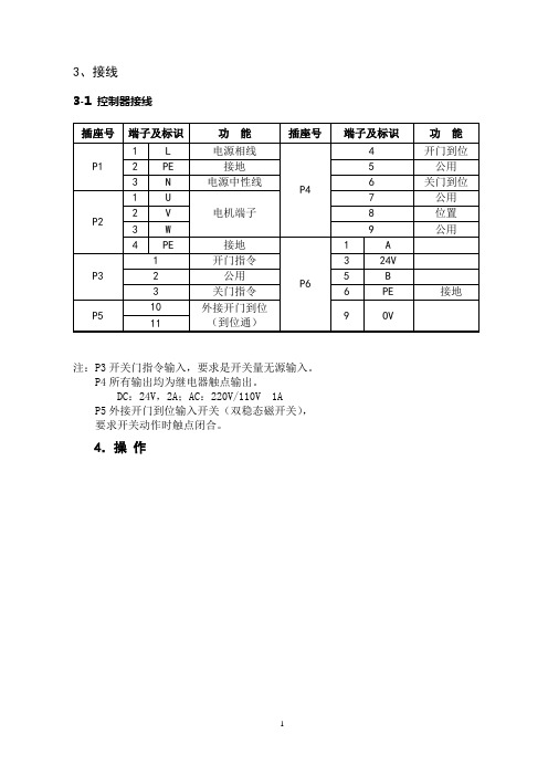
3、接线3-1 控制器接线注:P3开关门指令输入,要求是开关量无源输入。
P4所有输出均为继电器触点输出。
DC:24V,2A;AC:220V/110V 1A P5外接开门到位输入开关(双稳态磁开关),要求开关动作时触点闭合。
4.操作4-2 基本操作设定的基本操作方法如下所示。
这种方法用来设定开门总速度值从0.5m/s上升至0.7m/s,其它参数设定请参阅功能表。
4-3 系统参数可以通过前面板上的薄膜型按键改变和设定参数,以调节出所需要的开关门特性。
例如开关速度等。
被选定的参数号和设定的参数值通过四位LED显示屏显示出来。
同时可参看上页曲线图进行调整。
※注:设定参数时必须先断开开关门输入信号,否则按P键将不起作用。
如果间断性地按△或▽键,数值将一步一步地改变,如果长时间地按下这些键,数值将快速地改变。
如果出现不慎将参数错误设定,通过将参数F017设定为1,并按P键,可以将所有参数都复位到出厂设定值。
※注:参数F022—F032由厂方设定,一般情况下用户勿须现场设定。
6.调试说明6-1 两个关键词的解释1)脱机运行状态:脱开电梯主控制器、脱开层门装置,门机单独运行的状态。
2)外接开门到位开关:在门机底板上安装一双稳态磁开关、开关动作触点闭合,门机控制器得到开门到位信号,开门到位时通。
6-2、门机控制器调试的具体步骤1)按照顺序安装门机完毕,调整好门机高度和位置、轿门扇、门刀;让门机处于脱机运行状态,保证轿门无阻碍开门到位和关门到位。
2)检查门机控制器的输入电源:AC220V±15%;如电源电压不在AC220V±15%范围内,切勿上电,否则会损坏门机控制器。
3)确认输入电源电压正常,打开门机控制器电源开关。
初上电,门机控制器显示已存出厂门宽度脉冲数,以自学习速度向开门方向运行,直到外接开门到位开关闭合向门机控制器输入开门到位信号,同时操作面板上外接到位开关指示灯DSIN亮,表示门机已开门到位。
SANKEN变频器的使用说明2

OL(过载)
nOnE
47
异常内容的存储
(前一次)
48
异常内容的存储
(前二次)
49
异常内容的存储
(前三次)
50
清除存储的异常内容
1:消除
—
51
警报跳脱后自动复归时
警报继电器输出的选择
0:继电器无输出
1;继电器输出信号
0
注:指令码左边的★标记表示在变频器运转中不能改变此项的功能设定。
1~7:DC制动量的调整
0
26
DC制动时间的设定
1~200秒
1
★27
最高频率的截止点
0:无截止点
1:截止点为120 HZ
1
28
过电流的
防失速模式切换
0:防失速功能不动作
1:加速时把时间延长为2倍,恒速时以4倍减速时间来变化。
2:加速时把时间延长为4倍,恒速时以2倍减速时间来变化。
3:加速时使频率变化停止,
※2AC2
第2加速时间选择端
AC2-COM短路时,可选择第2加速时间。
※2DC2
第2减速时间选择端
DC2-COM短路时,可选择第2减速时间。
※2IOG
寸动运转端
IOG-COM短路时,可选择寸动运转方式。
RST
复位信号端
将RST-COM短路0.1秒以上,即可解除警报状态。
E S
紧急停止端
(连接外部热敏器等)
38
制动电阻的选择
1:通常时及使用外部专用电阻时
1
★39
电动机转向的固定功能
0:正反转均可
1:只可正转
2:只可反转
0
40
数据的锁定功能
F-ES100 使用说明书
地址:厦门市集美区软件园三期诚毅大街370号A06栋11层1/23F-ES100使用说明书文档版本密级V1.0.0产品名称:F-ES100共23页F-ES100使用说明书此说明书适用于下列型号产品:型号产品类别F-ES100-5.0V(电子式)电子式5.0V 供电F-ES100-3.3V(电子式)电子式3.3V 供电F-ES100-5.0V(模拟量)模拟量5.0V 供电F-ES100-3.3V(模拟量)模拟量3.3V 供电客户热线:400-8838-199网址:地址:厦门集美软件园三期A06栋11层文档修订记录日期版本说明作者2021.07.15V1.0.0初始版本HCW2/23地址:厦门市集美区软件园三期诚毅大街370号A06栋11层地址:厦门市集美区软件园三期诚毅大街370号A06栋11层3/23著作权声明本文档所载的所有材料或内容受版权法的保护,所有版权由厦门四信通信科技有限公司拥有,但注明引用其他方的内容除外。
未经四信公司书面许可,任何人不得将本文档上的任何内容以任何方式进行复制、经销、翻印、连接、传送等任何商业目的的使用,但对于非商业目的的、个人使用的下载或打印(条件是不得修改,且须保留该材料中的版权说明或其他所有权的说明)除外。
商标声明Four-Faith 、四信、、、均系厦门四信通信科技有限公司注册商标,未经事先书面许可,任何人不得以任何方式使用四信名称及四信的商标、标记。
产品外形图注:不同型号配件和接口可能存在差异,具体以实物为准。
目录第一章产品简介 (5)1.1产品F-ES100概述 (5)1.2产品特点 (5)1.3工作原理框图 (7)第二章技术指标 (8)2.1产品规格和技术指标 (8)第三章功能描述 (12)3.1测量功能 (12)3.2计量功能 (12)3.3时钟功能 (12)3.4冻结功能 (12)3.5事件记录功能 (13)3.6通信功能 (13)3.7数字脉冲输出功能 (13)3.8指示灯 (13)第四章结构、安装与接口定义 (14)4.1安装注意事项 (14)4.2装箱清单 (14)4.3尺寸与安装 (15)4.4接口定义 (16)第五章通信 (18)5.1通信使用说明 (18)5.2101通信协议 (18)5.3链路层 (18)5.3.1传输帧格式 (18)5.3.2固定帧长格式 (18)5.3.3可变帧长格式 (20)5.4链路传输规则 (21)5.5信息体地址 (22)4/23地址:厦门市集美区软件园三期诚毅大街370号A06栋11层地址:厦门市集美区软件园三期诚毅大街370号A06栋11层5/23第一章产品简介1.1产品F-ES100概述F-ES100嵌入式1路电子式(模拟量)线损模块是一种基于电压/电流传感器的10KV 配电高压计量装置,为10KV 配电线路分段式、分支式、柱上开关、环网柜等设备节点处的高压电能计量和实时监测的需求提供解决方案,是10KV 配电线路精细化线损管理系统的重要组成部分。
AVF100-0244K说明书
AVF100-0244K说明书
一、主要参数
系列:VF100
产地:中国
应用范围:高分段
电源相数:3相
额定电压:AC380到460v
供电电压:380v
适配电机功率:2.2KW
滤波器:内置滤波器
直流电源性质:直流电压
控制方式:矢量控制
输出电压调节方式:V或F控制
额定电流:9
物料编号:AVF1000224
外型:塑壳
可售卖地:全国
型号:AVF1000224
二、特点:
1、力矩特性提高:松下变频器VF100系列具有简单矢量控制功能、具有Autotuning功能。
2、操作性提高:频率设定电位器进行了改良、可拆卸式的操作面板、具有复制参数功能的操作面板。
3、网络通信:配备RS485通信接口、ModbusRTU对应。
4、保护功能扩充:输出短路保护(负载短路、接地短路)、具有高速电流限制功能(OC跳闸减少)、耐环境性(保护结构IP20)。
5、使用性提高:装配紧密、端子接线的施工性提高、散热风扇可ON或OFF控制、简易模式运转、可通过多段速功能和定时功能(或计数功能)运转。
6、小巧:为了满足各类机器小型化的需要,松下变频器VF0系列松下变频器VF0系列实现了同类产品中小型化。
7、操作简单:采用了新设计的调频电位器,使调频操作简单轻松,而且用操作盘就可容易地操作正转或反转。
BEDFORD变频器说明书

B801系列使用手册V1.4目录1、前言 (1)2、安全注意事项 (1)3、产品检查3.1检查步骤 (1)3.2型号说明 (1)4、安装4.1外型尺寸 (2)4.2使用环境 (2)4.3注意事项 (2)5、配线5.1基本接线图 (4)5.2操作注意 (5)6、数字操作器使用方法6.1显示器及操作键 (5)6.2操作键的使用 (5)7、测试运转 (6)7.1掌握一些相应的调节方法或许能让您获得更理想的使用效果 (6)7.2键盘操作模式 (6)7.3键盘操作正、反转模式 (7)7.4控制端子操作模式 (7)7.5参数恢复出厂设定值 (7)7.6参数修改后储存条件 (7)8、显示屏上的符号解释 (8)9、参数和数据表9.1参数一览表 (11)9.2参数说明 (13)10、故障指令及对策10.1故障发生时处理排除的注意事项 (18)10.2异常故障处理对策表 (18)10.3运转注意事项 (19)11、B801-200V系列标准规格 (20)12、B801-400V系列标准规格 (21)1、前言感谢您选用B801系列高性能变频器,使用前务必请认真阅读本说明书。
2、安全注意事项变频器是电力电子新产品,为了您的安全,本手册中有“危险”“注意”等符号是提醒您在搬运、安装、运转、检查变频器时的安全防范事项。
! 危险错误使用时,可能造成人员伤亡。
! 注意错误使用时,可能造成变频器或系统损坏。
3、产品检查3.1检查步骤•变频器是否符合所订购的型号与规格。
•检查在运输过程中,变频器是否因运送不慎造成损伤,若有损坏请勿接入电源。
•保修单编号是否与变频器一致。
当您发现有上述问题时,请立即通知有关销售商的业务人员。
3.2型号说明4、安装4.1外型尺寸4.2使用环境变频器安装的环境对变频器正常功能的发挥及其使用寿命有直接的影响,因此,变频器安装的环境必须符合下列条件:•周围温度:壁挂型,-10~45℃;柜内封闭型,-10~40℃。
D+RF系列220V(带显示)说明书中文
D+RF系列220V(带显示)说明书中文本手册适用于D+R F系列智能型电动执行机构的安装、调试、使用和维护指导。
警告:调试过程中进行全开/全关位置设置时,在接近阀门的全开或全关位置时,应该为手轮操作,严禁使用点动按钮进行点动操作,否则可能由于位置走过引起阀门或者执行器的损坏,由于此种原因造成执行器损坏,D+R概不负责。
警告:在安装、调试、使用和维护D+R F系列智能型电动执行机构前,必须仔细阅读本手册,严格按照安全操作规程操作,以防造成人身安全事故。
警告:在操作过程中,必须小心高温、高压、易燃、易爆、有毒及腐蚀性介质和高电压、强大外力等危险情况。
警告:必须严格按照规范、图纸和手册等的要求进行正确的安装、接线、调试、使用、储存和维护,否则有可能导致严重伤害、损坏设备。
目录1运输和储存 (1)2工作环境 (1)2.1环境温度 (1)2.2外壳防护等级 (2)3执行器安装 (2)3.1安装位置 (2)3.2直行程联接 (2)3.3角行程联接 (3)4电气连接和调试 (5)4.1接线端子排—10端子 (5)4.2400V AC13端子接线端子 (7)5调试 (9)5.1显示状态 (9)5.2三相接入电源的相序检测 (10)5.3进入设置状态 (11)5.4过流保护设定 (11)5.5全开位置设定 (12)5.6全关位置设置 (13)5.7信号故障位置设定 (14)5.8输入信号4M A校准 (14)5.9输入信号20M A校准 (15)5.10反馈信号4M A校准 (15)5.11反馈信号20M A校准 (16)5.12死区值设定 (16)5.13正反作用选择 (17)5.14保存/恢复设置 (18)6设备维护、保养 (19)6.1设备维护周期 (19)6.2润滑 (19)7故障信息及处理一览表 (20)11 运输和储存运输过程中执行机构的外包装可采用木箱、高强度纸箱等,内部应填充发泡物。
执行器在箱内摆放,手轮不能朝下,不能承受来自任何方向得压力,以免造成设备损坏或划伤。
SJ100型日立变频器操作说明

SJ100型日立变频器操作说明SJ100型日立变频器操作说明该变频器内部参数我厂已经设定,出厂时设定为“就地”操作,但只需简单的调试就能实现“就地/集控”的操作转换。
RUN PRG HIACHI 50.0POWER Hz A RUN STOPRESETMIN MAXFUN 12STR 电源指示灯显示单位Hz/A指示灯电位器允许指示灯储蓄键电位器向上/向下按键功能键停止/复位按纽运行按纽运行允许指示灯编程/监视指示灯运行/停止指示灯参数显示一、就地操作按“功能键”显示“d01”,按“向下键”显示“H- -” ,继续按“向下键”直至显示“A- -” ,按“功能键”显示“A01”,再按“功能键”显示“01”,按“向下键”显示“00”,电位器控制转速,按“储蓄键”,电位器允许指示灯亮。
按“向上键”显示“A02”,按“功能键”显示“01”,再按“向上键”显示“02”,键盘操作,按“储蓄键”,运行允许指示灯亮。
按“功能键”显示“A- -” ,按“向上键”直至显示“d01”,输出频率监视,再按“功能键”,显示“0.0”,即为输出频率值,就地操作设定完毕。
按“运行”按纽,电机运行,按“停止/复位按纽”,电动机停止。
二、集控操作按“功能键”显示“d01”,按“向下键”显示“H- -” ,继续按“向下键”直至显示“A- -” ,按“功能键”显示“A01”,再按“功能键”显示“00”,按“向上键”显示“01”,控制端子操作,按“储蓄键”存储参数。
按“向上键”显示“A02”,按“功能键”显示“02”,再按“向下键”显示“01”,控制端子操作,按“储蓄键”存储参数。
按“功能键”显示“A- -” ,按“向上键”直至显示“d01”,输出频率监视,再按“功能键”,显示“0.0”,即为输出频率值,现在频率的高低由DCS 系统4~20mA 信号控制,集控操作设定完毕。
合上“Q3”(控制柜内C45单级空气开关)变频器即为“集控”运行,这时电动机的“起动/停止”及“转速”均与DCS 系统控制。
赫茨RF300A变频器说明书
30
0.60
30
0.087
33
2
RF300A-015G/018P-4
40
0.42
40
0.066
33
2
RF300A-018G/022P-4
50
0.35
50
0.052
40
1.3
RF300A-022G/030P-4
60
0.28
60
0.045
50
1.08
RF300A-030G/037P-4
80
0.19
80
0.032
附录B 频变器相关附件选型表 RF300A
RF300A 列系矢量通用型变频器 RF300A
附录B 频变器相关附件选型表
RF300A
器
附录C 功能参数简表
RF300A 列系矢量通用型变频器
(备注:J1跳线中PANEL与AI1 连接为键盘电位器输入,PORT 与AI1连接为外部端子AI1输入。)
B.2 动制电阻/制动单元选型 B.2.1 型选参考
RF300A
附录B 频变器相关附件选型表 22
RF300A 列系矢量通用型变频器
附录B 频变器相关附件选型表
RF300A 列系矢量通用型变频器
附录B 频变器相关附件选型表
RF300A RF300A
RF300A 列系矢量通用型变频器 RF300A
时间t
正反转 死区时间
定变频器设正反转过渡过程中,在输出零 频处的过渡时间。 如下图示:
输出频率f
死区时间 正转
时间t
反转
图6-4 反正转死区时间示意图
运行频率低于 频率下限动作 功能码是确该定当设定频率低于下限频率 时变频器的运行状态。 以频率下0限:运行。 停机。 1: 休眠待机2。 :当设定频率低于下限频率 时,变频器自由停车;当设定频率再次大于或 等于下限频率时,变频器自动运行。 意:该功能注仅在下限频率大于零时有效。
Ace使用说明书中文
前言
感谢您选购本公司生产的高性能多功能变频器“FRENIC-Ace”系列产品。该产品是用于可变速运转 3 相电机的装置。
本手册记载了 FRENIC-Ace 的操作方法和各种运转方法以及外围设备的选择等全部信息。使用前,请仔细阅读使用 说明书,并正确使用。操作有误时,会影响正常运转、降低使用寿命或导致故障。
第 3 章 操作面板的操作 3.1 操作面板各部位的名称和功能 .................................................................................................................. 3-1 3.2 操作模式概要 ........................................................................................................................................... 3-3
第 4 章 试运行步骤 4.1 试运行步骤的流程图 .................................................................................................................................. 4-1 4.2 接通电源前的确认...................................................................................................................................... 4-2 4.3 接通电源以及之后的确认........................................................................................................................... 4-3 4.4 适用电机的等级切换(ND/HD/HND/HHD 规格) ...................................................................................... 4-3
CHF100A变频器常用功能设置

3:三线式运行控制2。
4
0~65535
50HZ 50HZ 0~50HZ
0
0
0:V/F控制。1:无PG矢量控制。2:转矩控制。
1 0:键盘指令通道。1:端子指令通道。2:通讯指令通道。
0:有效,变频器掉电存储。1:有效,变频器掉电不存储。
2:无效,键盘和端子功能无效,设定自动清零。3:运行时
有效,停机时设定自动清零。
1
0~2
0
0~1
0
0~3
0
0.1~3600.0S 100
0ቤተ መጻሕፍቲ ባይዱ1~3600.0S 100
0:键盘设定。1:模拟量AI1设定。2:模拟量AI2设定。
0
0 0
说明 0:键盘指令通道("LOCAL/REMOT"灯熄灭)。1:端子指令通
道("LOCAL/REMOT"灯显烁)。2:通讯指令通道 ("LOCAL/REMOT"灯点亮)。 机型确定
0:无操作。1:全面电机参数自学习。2:禁止。 0:无操作。1:恢复缺省值。2:清除故障。 0:直接起动。1:先制动。2:转速追踪。 0:减速停车。1:自由停车。 0:禁止再起动。1:允许再起动。
3:三线式运行控制。4:正转寸动。5:反转寸动。6:自由
停车。7:故障复位。8:运行暂停。9:外部故障输入。
0:无功能。1:正转运行(FWD)。2:反转运行(REV)。
3:三线式运行控制。4:正转寸动。5:反转寸动。6:自由
停车。7:故障复位。8:运行暂停。9:外部故障输入。
0:无功能。1:正转运行(FWD)。2:反转运行(REV)。
3:三线式运行控制。4:正转寸动。5:反转寸动。6:自由
RF 容量测量仪说明书
CAPACITANCE LEVEL MEASUREMENT BASIC MEASURING PRINCIPLEA capacitor is formed when a level sensing electrode isinstalled in a vessel. The metal rod of the electrode actsas one plate of the capacitor and the tank wall (orreference electrode in a non-metallic vessel) acts as theother plate. As level rises, the air or gas normallysurrounding the electrode is displaced by materialhaving a different dielectric constant. A change in thevalue of the capacitor takes place because the dielectricbetween the plates has changed. RF (radio frequency)capacitance instruments detect this change and convertit into a relay actuation or a proportional output signal.The capacitance relationship is illustrated with thefollowing equation:C= 0.225 K( A)Dwhere:C=Capacitance in picoFaradsK=Dielectric constant of materialA=Area of plates in square inchesD=Distance between the plates in inchesMETAL SHELL MEASURED MATERIAL SENSOR INSULATIONMETAL ELECTRODEEARTH GROUNDThe dielectric constant is a numerical value on a scale of 1 to 100 which relates to the ability of the dielectric (material between the plates) to store an electrostatic charge. The dielectric constant of a material is determined in an actual test cell. Values for many materials are published by the National Institute of Standards and Technology.In actual practice, capacitance change is produced in different ways depending on the material being measured and the level electrode selection. However, the basic principle always applies. If a higher dielectric material replaces a lower one, the total capacitance output of the system will increase. If the electrode is made larger (effectively increasing the surface area) the capacitance output increases; if the distance between measuring electrode and reference decreases, then the capacitance output decreases.Level measurement can be organized into three basic categories: the measurement of non-conductive materials, conductive materials and proximity ornon-contacting measurement. While the following explanations oversimplify the measurement, they provide the basics that must be used to properly specify a capacitance measurement system.ⅢNon-Conductive Materials—As previously stated, capacitance changes as material comes between the plates of the capacitor. For example, suppose thesensor and the metal wall are measuring theincreasing level of a non-conductive hydrocarbon.Figure 1 depicts a typical system.While the actual capacitive equation is very complex, it can be approximated for the above example as follows:C=0.225 (K air x A air)+0.225 (K material x A material)D air D materialSince the electrode and tank wall are fixed in place, the distance between them will not vary. Similarly, the dielectric of air and of the measured material remain constant (air is 1 and the hydrocarbon is 10). Consequently, the capacitance output of the system example can be reduced to this very basic equation:C= (1 x A air) + (10 x A material)As this equation demonstrates, the more material in the tank, the higher the capacitance output will be. The capacitance is directly proportional to the level of the measured material.ⅢConductive Materials—The same logic for non-conductive materials applies for conductivematerials, except that conductive material acts as the ground plate of the capacitor, rather than the tankFigure 1- Capacitive MeasurementIn Non-Conductive MediaK-10Kwall. This changes the distance aspect of the equation, whereby the output would becomparatively higher than for a non-conductivematerial. However, it still remains fixed; therefore, as level rises on the vertically mounted sensor, the output increases proportionally.NOTE: A material is considered conductive when it has a conductivity value of greater than 10 microSiemens/cm.ⅢProximity (non-contacting) Measurements —The level sensing electrode is normally a flat platemounted parallel to the surface of the material. The material, if conductive, acts as the ground plate of the capacitor. As level rises to the sensor plate, the effective distance between plates is decreased, thus causing an increase in capacitance. In non-conductive materials, the vessel acts as the ground plate and the mass of material between the plates is the variable. In the measurement of non-conductive and conductive materials, the area changes and the distance is fixed. Proximity level measurement is exactly the opposite in that the area is fixed, but distance varies.Proximity level measurement does not produce a linear output and can only be used when the level varies by several inches.Some typical level sensor installations for measuring conductive and non-conductive materials and for proximity level measurement are shown in Figures 2and 3.APPLICATIONSApplications for RF point level controls and analog transmitters/controllers are widespread. Granular applications range from light powders to heavyaggregates. Applications in liquids, slurries and pastes are commonplace. Capacitance level can also be used to detect the interface between two immiscible materials.Selecting the proper level sensing electrode andinstalling it in the proper location are important factors that contribute to the success of any application. A thorough understanding of these factors is required.•Electrode Selection —The electrode is the primary measuring element and must be capable of producing sufficient capacitance change as it becomes submerged in the measured material.Several electrode types are offered, each having specific design characteristics. Capacitance (per foot of submersion) vs. dielectric constant curves are published for each type as installed in various size vessels. For non-conductive materials, these curves are non-linear. Figure 4 shows a typical set of curves. As the size of the tank gets smaller, the capacitance per foot of submersion increases. A conductive material essentially makes the tank be the size of the electrode insulation.Note: Continuous level transmitter applications require aminimum span of 10.0 pF and a maximum span of 10,000 pF.In this case, the saturation capacitance is used.Table A lists basic capacitance values for different electrodes and tank sizes.CAPACITANCE LEVEL PROBE SELECTION GUIDEThe simplest applications are clean, non-coatingconductive liquids (such as many water-based liquids)in metallic tanks. An insulated probe must be used, and the fluid is grounded to the probe through the tank. The capacitance change per foot = the saturation capacitance.Clean, non-coating conductive liquids (such as many water-based liquids) in non-metallic tanks require the use of a concentric probe. The capacitance change per foot = the saturation capacitance. See application note “RF Level Measurement in Lined Vessels withGrounded Shell” for details on lined or coated metallic tank applications. Clean, non-coating non-conductive liquids (such as many hydrocarbons ) in non-metallic tanks require the use of a concentric probe. The Figure 2Figure 3K-11GENERAL PURPOSE PROBE - TFE INSULATED70605040302010DIELECTRIC CONSTANTC A P A C I T A N C E P E R F O O T (p F )capacitance change per foot depends upon the dielectric constant of the material.Clean, non-coating non-conductive liquids (such as many hydrocarbons ) in metallic tanks require special consideration. A bare (un-insulated) probe can be used,but one must insure that the probe does not come in contact with any conductive liquid that may contaminate the non-conductive liquid (such as water in oil). If this occurs, the output will be driven to full scale, regardless of the actual level in the tank. Note that an insulated probe can also be used. The probe’s metal fitting must be grounded to the metal tank wall, and the distance from the tank wall to the probe must be constant along the entire length of the probe, to provide a linear change in analog output per change in fluid height. If this is not the case (i.e. the tank is “irregular” in shape),or if the tank is greater than 15 ft in diameter, a concentric probe should be used. The capacitancechange per foot depends upon the dielectric constant of the material, as well as the tank diameter (tank diameter does NOT effect the concentric probe).After making a preliminary probe selection based upon the above considerations, it is important to insure that the capacitance of the probe selected meets thefollowing limitations: the capacitance at zero level in the tank is less than 500 pFd, and the maximumcapacitance at full span level is more than 10 pFd but less than 10,000 pFd. Also, the zero to span ratio must not exceed 10 to 1. That is, if the zero pf value is 200,the span must be at least 20 pf.THIS IS CALCULATED AS FOLLOWS:For the LV5100 probe, TFE insulated, in a 24" tank,with a dielectric = 2 (air has a much lower dielectric, so this calculation is very conservative), the pFd per foot is 6 pFd. The maximum length of this probe is 12 ft, so that the maximum probe capacitance in the open air is = (6 x 12) + (42 pFd - gland capacitance) = 114 pFd,which is less than 500 pFd. Note that no probe has greater than 50 pFd gland capacitance.Helpful Hint500 pFd can only be exceeded with anLV5300 probe of greater than 25 ft length, or greater than 9 ft length in the LV5102 PVDF insulated heavy duty probe, or greater than 91⁄2ft length in the polyethylene insulated heavy duty probe.For the LV5100 probe, TFE insulated, in a 24" tank,with a dielectric = 2 (this is a typical value forhydrocarbons) the pFd per foot is 6 pFd. The maximum length of this probe is 12 ft, so that the maximum span capacitance is = (6 x 12) + (0 pFd - gland capacitance is not added to the span) = 72 pFd, which is greater than 10 pFd and less than 10,000 pFd. Note that if the probe were only 1 ft long, that the maximum spancapacitance would be only 6 pFd, which is less than the required 10 pFd.Helpful Hints• 10,000 pFd can only be exceeded with an LV5300 probe of greater than 39 ft length, or greater than 10 ft length in the LV5202 or LV5212 PVDF insulated enhancedperformance probe with a conductive liquid.•To have less than 10 pFd span, one must have a span of less than 1 ft fornon-conductive liquid with dielectric less than 20and in a tank greater than 1"diameter.•Note that the “Saturation Capacitance”values should be used when the liquid is conductive (i.e.above 20 microsiemens/cm),such as water-based fluids that are not ultra-pure or distilled or deionized.Field Calibration Required:Capacitive level transmitters must always be calibrated for zero and span in the field. The concentric probe can be tested in a bucket or small tank of the liquid to be measured; all other probes must be calibrated after final installation by changing the material level and adjusting the zero and span pots.Unlined Plastic Tanks:Due to the low gains in large tanks, concentric probes are recommended for unlined plastic tanks to minimize this effect and to provide a ground reference.Large Diameter Metal Tanks for Low Dielectric Fluids (such as Hydrocarbons)Due to the low gains in large tanks, concentric probes are recommended for metal tanks greater than 20 foot diameter used to measure low dielectric fluids (such as hydrocarbons). Also, if concentric probe is impractical,mount closer to tank wall if possible.•Electrode Location —Mounting positions should be carefully considered. They must be clear of the inflow of material as impingement during a filling cycle can cause serious fluctuations in the capacitancegenerated. Side mounted electrodes with point level controls are typically mounted at a downward angle to allow the measured material to drain or fall from the electrode surface.Electrodes mounted in nozzles should contain a metal “sheath” extending a few inches past the nozzle length. The sheath renders that part of theFigure 4K-12Kelectrode insensitive to capacitance change, and therefore, ignores the material which may build up in the nozzle.NOTE: In addition to the electrode selection and location factors,there are other considerations which can have a significant impact on the measurement. See “Special Considerations” below.1. Temperature —The dielectric constant of some materials varies with temperature which affects the capacitance measured by the electrode.Generally, materials with a higher dielectric constant are less affected by temperaturevariation. The temperature effect is usually given in the tables of dielectric constants.WARNINGThe effect of changing temperature and changing dielectric can not be quantified; if temperature or dielectric constant change, it is recommended that the level transmitter be calibrated at each temperature and dielectric constant value to quantify the effect of the changes .2. Moisture Content —The dielectric constant of granular materials changes with changing moisture content. This variation can cause significant measurement errors, so eachapplication must be carefully examined. Accuracy requirements determine the amount of moisture change that is tolerable.WARNINGThe effect of changing moisture content can not be quantified; if moisture content changes, it is recommended that the level transmitter be calibrated at each moisture level value toquantify the effect of the changes. In addition,the LV5000 series level transmitter should NOT be used with hygroscopic materials (i.e. those materials that absorb moisture from the atmosphere).3.Static Change —Air-conveyed, non-conductive granular materials such as nylon pellets build up a static charge on the electrode which can damage the electronic components in the measuring instruments.WARNINGThe LV5000 series level transmitter should NOT be used with materials that could build up static charges.4. Composition —The dielectric constant of the measured material must remain constant throughout its volume. Mixing materials with different dielectric constants in varying ratios will change the overall dielectric constant and theresultant capacitance generated. Solutions having a high dielectric constant are less affected due to the saturation capacitance of the electrodesystem. See capacitance vs. dielectric constant curve in Figure 4.WARNINGThe LV5000 series level transmitter should NOT be used with materials of varying compositions.5. Conductivity —Large variations in the conductivity of the measured material can introduce measurement error. The proper electrode selection can minimize this effect. A thick wall electrode insulation is recommended in this case.WARNINGThe effect of changing conductivity can not be quantified; if conductivity changes, it is recommended that the level transmitter becalibrated at each conductivity value to quantify the effect of the changes.6.Material Buildup —The most devastating effect on the accuracy of RF capacitive measurements is caused by the buildup of conductive material on the electrode surface. Non-conductive buildup is not as serious since it only represents a small part of the total capacitance. Latex, carbon black, and fine metal powders are examples of materials that produce conductive coatings.Special ConsiderationsCONTINUOUS LEVEL MEASUREMENTVarious methods are used to minimize the coating error. These include proper electrode selection, higher frequency measurements, phase shifting and conductive component subtraction circuits.Coating error is illustrated by the diagram shown in Figure 5. The submerged portion of the electrodegenerates nearly a pure capacitive susceptance. Since the electrode is insulated, a conductive component is virtually non-existent. However, the upper section of the electrode, coated with conductive material, generatesan error signal consisting of a capacitive susceptance and a conductive component. The result is anadmittance component which is 45°out of phase with the main level signal. A study of transmission line theory is required to prove this phenomenon. Anequivalent circuit for the coated section is shown as a ladder network producing the phase shifted error signal.Figure 5K-13Admittance Vector DiagramFigure 6One means of cancelling the error signal is to measure the conductive component (c) shown in Figure 6,Method A. Since the 45°relationship exists, thecapacitive error component (e) is the same magnitude and can be subtracted from the total output signal,thereby effectively canceling the error signal.Another cancellation method is to introduce a 45°phase shift to the entire measurement as shown in Figure 7,Method B. This automatically cancels the coating error portion because the conductance component (c) still has the same magnitude as the error component (e),resulting in the appropriate level signal. Instruments which incorporate these techniques are known as “admittance” types.The coating error can also be reduced by increasing the capacitive susceptance. This is accomplished by increasing the frequency of measurement and/or decreasing the electrode insulation wall thickness.It should be noted that any of these techniques cannot perfectly cancel the coating effect, but each tends to reduce the error.These are process control devices which require careful evaluation of the listed considerations to provide satisfactory results.Reproduced with the permission of Great Lakes Instruments.K-14KCANADA www.omega.ca Laval(Quebec) 1-800-TC-OMEGA UNITED KINGDOM www. Manchester, England0800-488-488GERMANY www.omega.deDeckenpfronn, Germany************FRANCE www.omega.frGuyancourt, France088-466-342BENELUX www.omega.nl Amstelveen, NL 0800-099-33-44UNITED STATES 1-800-TC-OMEGA Stamford, CT.CZECH REPUBLIC www.omegaeng.cz Karviná, Czech Republic596-311-899TemperatureCalibrators, Connectors, General Test and MeasurementInstruments, Glass Bulb Thermometers, Handheld Instruments for Temperature Measurement, Ice Point References,Indicating Labels, Crayons, Cements and Lacquers, Infrared Temperature Measurement Instruments, Recorders Relative Humidity Measurement Instruments, RTD Probes, Elements and Assemblies, Temperature & Process Meters, Timers and Counters, Temperature and Process Controllers and Power Switching Devices, Thermistor Elements, Probes andAssemblies,Thermocouples Thermowells and Head and Well Assemblies, Transmitters, WirePressure, Strain and ForceDisplacement Transducers, Dynamic Measurement Force Sensors, Instrumentation for Pressure and Strain Measurements, Load Cells, Pressure Gauges, PressureReference Section, Pressure Switches, Pressure Transducers, Proximity Transducers, Regulators,Strain Gages, Torque Transducers, ValvespH and ConductivityConductivity Instrumentation, Dissolved OxygenInstrumentation, Environmental Instrumentation, pH Electrodes and Instruments, Water and Soil Analysis InstrumentationHeatersBand Heaters, Cartridge Heaters, Circulation Heaters, Comfort Heaters, Controllers, Meters and SwitchingDevices, Flexible Heaters, General Test and Measurement Instruments, Heater Hook-up Wire, Heating Cable Systems, Immersion Heaters, Process Air and Duct, Heaters, Radiant Heaters, Strip Heaters, Tubular HeatersFlow and LevelAir Velocity Indicators, Doppler Flowmeters, LevelMeasurement, Magnetic Flowmeters, Mass Flowmeters,Pitot Tubes, Pumps, Rotameters, Turbine and Paddle Wheel Flowmeters, Ultrasonic Flowmeters, Valves, Variable Area Flowmeters, Vortex Shedding FlowmetersData AcquisitionAuto-Dialers and Alarm Monitoring Systems, Communication Products and Converters, Data Acquisition and Analysis Software, Data LoggersPlug-in Cards, Signal Conditioners, USB, RS232, RS485 and Parallel Port Data Acquisition Systems, Wireless Transmitters and Receivers。
RF开关说明书
RF CHARACTERISTICSFrequency range :0 - 12.4 GHz Impedance :50 OhmsELECTRICAL CHARACTERISTICSActuator:FAILSAFE Nominal current **:310 mAActuator voltage (Vcc):12V (10.2 to 13V)Terminals :solder pins (250°C max. / 30 sec.)Indicator rating :1 W / 30 V / 100 mA TTL inputs (E)- High level :2.2 to 5.5 V / 800µA at 5.5 V - Low level:0 to 0.8 V / 20µA at 0.8 VMECHANICAL CHARACTERISTICSConnectors :N female per MIL-C 39012Life:2.5 million cycles Switching Time***:< 15 ms Construction :Splashproof Weight:< 185 gENVIRONMENTAL CHARACTERISTICSOperating temperature range :-40°C to +85°C Storage temperature range:-55°C to +85°C(*Average power at 25°C per RF Path)(**At 25° C ±10%)(***Nominal voltage ; 25° C)60 dB 200 W0.50 dB Average power (*)700 W500 W400 W250 W0.15 dB 0.20 dB 0.25 dB 0.35 dB Isolation min 85 dB 80 dB 75 dB 70 dB Technical Data SheetSPDT Ramses N 12.4GHz Failsafe Indicators 12Vdc TTL Diodes Pins TerminalsR570122100PAGE 1/2ISSUE 11.04.14SERIE : SPDTPART NUMBER :This document contains proprietary information and such information shall not be disclosed to any third party for any purpose whatsoever or used for manufacturing purposes without prior written agreement from Radiall. The data defined in this document are given as an indication, in the effort to improve our products; we reserve the right to make any changes judged necessary.VSWR max Frequency (GHz)DC - 1 1 - 2 2 - 3 3 - 88 - 12.41.15 1.20 1.25 1.35 1.50Insertion loss maxDRAWINGGeneral tolerances : ±0.5 mm SCHEMATIC DIAGRAMC ↔ NC C.1NC E = 1C ↔ NOC.2NOTechnical Data SheetSPDT Ramses N 12.4GHz Failsafe Indicators 12Vdc TTL Diodes Pins TerminalsPAGE 2/2ISSUE 11.04.14SERIE : SPDTPART NUMBER :R570122100TTL input RF Continuity Ind.E = 0agreement from Radiall. The data defined in this document are given as an indication, in the effort to improve our products; we reserve the right to make any changes judged necessary.This document contains proprietary information and such information shall not be disclosed to any third party for any purpose whatsoever or used for manufacturing purposes without prior written RADIALL® R5701221000 - 12.4 GHz / Un : 12VLot : _ _ _ _LABEL。
BEST变频器说明书
止过热或火灾等发生。 ●请确认切断电源后,再拆卸或装入操作键盘,并固定前盖,以免接触不良,造成操
作器故障或不显示 ●请不要把变频器安装在含有爆炸性气体的环境里,否则有引发爆炸的危险 ●在海拔超过 1000 米的地区,变频器散热效果变差,请降档使用。 ●输出侧请不要安装空开和接触器等开关器件,如果由于工艺及其他方面需要必须安
三相 380V±15% 50/60Hz
90 110 132 90 110 132 176 210 253
200% 0.1 秒钟 225 275 332
4
功率 KW
适配电机
功率 KW
额定电
输
流A 电压 V
出 频率 HZ 过载
保护
额定电 输 流A
电压 V 入
频率 HZ
160 185 200 220 250 280 315 355 400 160 185 200 220 250 280 315 355 400
180% 10 秒钟 160% 0.1 秒钟
3.9 6.8 12 15 26
单相 220V±15% 50/60Hz
200% 0.1 秒钟
(注) 1)最大适配电机是指该型号变频器驱动的最大功率轻负载电机,并以 4 极电机为标准。 2)额定输出电流是指输出电压为 380V(或 220V)时的输出电流。 3)超载能力是以过电流与变频器的额定电流之比的百分数(%)表示的反复使用时必须等待变频器和 电机降到 100%负荷时的温度以下。 4)在电源电压以下可以任意设定输出电压(变频器输出端电压的峰值为直流电压),最大输出电压不 能大于电源电压。 5)电源容量随着电源侧的阻抗(包括输入电抗器和电线)的值而变化。
SINEE EM100手册

前言感谢您选用深圳市正弦电气股份有限公司研制的EM100系列变频器。
资料编号:31010019资料版本:109发布时间:2017-01EM100系列变频器是正弦电气研制推出的高性能、简易型交流电机驱动器。
稳定、可靠、易于使用是其重要特征。
本手册将为你提供EM100系列变频器的安装、配线、功能参数、日常维护、故障诊断等相关特性、及其操作方法与注意事项。
为了确保能够正确使用本系列变频器,充分发挥产品的卓越性能并确保使用者和设备的安全,在使用EM100系列变频器之前,请您务必详细阅读本手册。
不正确的使用可能会造成变频器运行异常、发生故障,甚至发生设备损坏、人身伤亡等事故!本使用手册为随机发送的附件,请妥善保管。
变频器首次与电机连接时,请您设定电机铭牌参数:额定频率、额定功率、额定电压、额定电流、额定转速、额定功率因数及电机接法。
由于我们始终致力于产品和产品资料的不断完善,因此,本公司提供的资料如有变动,恕不另行通知。
最新变动和更多内容,请访问 目录第一章安全注意事项 (3)1.1安全事项 (3)1.2注意事项 (6)第二章产品信息 (7)2.1产品确认 (7)2.2命名规则及铭牌 (7)2.3变频器型号 (8)2.4技术规范 (8)2.5产品部件说明 (10)2.6产品外形和安装尺寸 (11)第三章产品安装 (13)3.1机械安装 (13)3.2电气接线 (22)第四章操作与显示 (37)4.1操作与显示界面介绍 (37)4.2功能码查看及修改方法说明 (38)第五章功能参数表 (42)5.1功能代码表说明 (42)5.2功能参数表 (42)第六章参数说明 (54)第七章故障诊断及对策 (95)第八章电磁兼容性指导 (99)第九章保养和维护 (102)9.1变频器的日常保养与维护 (102)9.2变频器的保修说明 (103)附录A:EM100 MODBUS通讯协议 (104)附录B:选配件说明 (110)附录C:客户常见问题及处理措施 (111)第一章安全注意事项安全定义:在本手册中,安全注意事项分以下两类;危险:由于没有按要求操作造成的危险,可能导致重伤,甚至死亡的情况。
RFD(K)调速器说明书

零件序号及名称:特点RFD(K)型调速器具有独特的杠杆机构,可以根据不同工况改变杠杆比。
怠速工况,杠杆比小,以便低速时飞锤离心力较小的情况下对拉杆也有足够的控制能力,从而获得低而稳的怠速。
而在高速时,杠杆比大,控制灵敏。
RF D(K)型调速器既可以作为两极式用于车辆,又可以作为全程式用于工程机械。
尤其适用于起重汽车等工程用车;行车时用两极手柄,停车作业时使用全程手柄。
RFD—K型调速器具有负校正装置,它的功能是当发动机在全负荷高速范围时,增加供油量以提高发动机的输出功率,而在全负荷低速范围时则减少供油量,以便降低黑烟排量。
RFD型调速器的结构特点:RFD型调速器的结构如图31所示:飞锤固定在喷油泵凸轮轴上,当飞锤向外张开时,飞锤的滑块推动滑套沿轴向移动。
丁字块一端压配在滑套上,另一端与导杆下端由销轴相连,导杆中间的轴套通过销轴连接浮动杆。
浮动杆上端通过拉杆连接杆与供油拉杆相连,起动弹簧一端挂在前壳上,另一端挂在浮动杆上,浮动杆下端销子上的滑块嵌入拨叉槽内,拨叉通过偏心的曲柄与负荷手柄相连,转动负荷手柄可以改变供油拉杆的位移。
拉力杆和导杆一起悬挂在拉力杆轴上,在拉力杆底部装有销轴,该销轴装在拨叉上端的槽内。
调速弹簧一端挂在拉力杆上,另一端挂在弹簧摇臂上,转动弹簧摇臂可以改变调速弹簧的予紧力及当量刚度,以调整起作用转速。
大头调整螺钉固定在后壳下端,用于限制拉力杆的位置。
后壳后部装有稳速装置,发动机急速减速时,能使供油拉杆迅速回到怠速位置,以防止发动机急速降速时熄火。
RFD—K型调速器的结构:RFD—K型调速器的结构如图32所示:本结构与RF D型调速器结构基本相同,只是RFD一K型调速器装有负校正装置。
负校正摇架一端由销钉与导杆相连,另一端通过浮动杆轴与浮动杆相连,摇架和导杆之间装有复位扭簧,拉力杆上装有支点调节螺栓,以调整负校正行程,该螺栓头部与摇架内的销轴接触。
当负校正机构起作用时,调节螺栓会推动摇架,使供油拉杆向增油方向移动。
- 1、下载文档前请自行甄别文档内容的完整性,平台不提供额外的编辑、内容补充、找答案等附加服务。
- 2、"仅部分预览"的文档,不可在线预览部分如存在完整性等问题,可反馈申请退款(可完整预览的文档不适用该条件!)。
- 3、如文档侵犯您的权益,请联系客服反馈,我们会尽快为您处理(人工客服工作时间:9:00-18:30)。
额定电流 170A 210A 250A 300A 340A 380A 420A 480A 540A 610A
2.3A 4.5A 7.0A 10.0A 2.5A 3.7A 6.0A 9.0A 13A 17A 25A 32A 37A 45A 60A
二 变频器的安装
2.1 变频器的安装 RF100 系列有壁挂式和落地式两种,安装应保证足够的通风距离。
图 1-2
适用电机 空间电压矢量型
0.4KW 0.75KW 1.5KW 2.2KW 0.75KW 1.5KW 2.2KW 3.7KW 5.5KW 7.5KW
11KW 15KW 18.5KW 22KW 30KW 37KW 45KW 55KW 75KW
-4-
额定电流
2.3A 4.5A 7.0A 10.0A 2.5A 3.7A 6.0A 9.0A 13A 17A 25A 32A 37A 45A 60A 75A 90A 110A 150A
附图:变频器结构图……………………………………………………53
-1-
安全注意事项
安装、运行、维护或检查之前要认真阅读本说明书。 本说明书中有关安全运行的注意事项分类成“警告”或当心。
警告 指出潜在的危险情况,如果不避免,可能导致人身伤亡。 当心 指出潜在的危险情况,如果不避免,可能导致人身轻度或中度的伤害和设备损 坏。这也可用来对不安全操作进行警戒。
◆ 输入频率范围:47~63Hz
◆ 输出电压范围:0~额定输入电压
◆ 输出频率范围:0~600Hz
● 外围接口特性
◆ 可编程数字输入:6 路输入
◆ 继电器输出:1 路输出
◆ 集电极输出:1 路输出
◆ 模拟输入:VI:0~10V 输入
AI:0~20mA 输入
◆ 模拟输出:1 路模拟量输出,输出为:0~10V
◆ 故障保户功能:过流、过压、欠压、过温、缺相、过压(流)失速保护功能
◆ 8 段速控制功能,PLC 控制功能
1.2 变频器铭牌说明
变频器型号 适配电机功率 输入电压和频率 输出电流和频率
产品系列号
MODEL POWER INPUT OUTPUT S/N
RF100-1-R40-GB-1 0.4KW 1AC 220V 15% 50/60Hz 3AC 220V 2.3A 0-600.00Hz 080101XXXXXX
-7-
三 操作说明
3.1 面板结构说明,如下图所示 RF100-2 系列机型面板如下:
图 3-1 RF100-1 系列机型面板如下:
图 3-2 3.2 按键说明
RF100-2 系列机型面板说明如表 3-1: 表 3-1
按键 按键名称 按键功能说明
RUN 运行键
按下该键马上运行
STOP 停机键
按下该键马上停机
移位键
在参数和功能码编辑时,用来选择数据位,还可以循环查询运行过程中的状
态
JOG 点动键
ห้องสมุดไป่ตู้
按着不放,点动运行,放开回到电动前状态
PRG 编程键
按下该键,进入功能码编辑状态,再次按下编程键,返回上次状态
SET 设置键
在功能码编辑状态,按下该键,进入参数编辑状态,再按该键,保存调整后
的参数返回功能码编辑状态
U、V、W
变频器输出端子
P、B
外接制动电阻
接地端子
R、S、T
变频器电源输入端
ACN、ACL
变频器电源输入端
2.4 控制端子及说明
1)RF100-1 控制端子示意图
功能说明 接三相交流电机 接制动电阻两端 接地 接三相 380V 电源 接单相 220V 电源
图 2-7 说明:CM 为 X1~X6 端子的公共地。GND 为模拟输入输出和+10V 的公共地。FM 为模 拟输出(0~10V);AI 为模拟电流输入(0~20mA);VI 为模拟电压输入(0~10V)。 Y1 为集电极输出,YCM 为其相对应的地。RA、RB、RC 为继电器输出端。常态时, RA、RB 闭合,RB、RC 断开;继电器输出时,RB、RC 闭合,RA、RB 断开。 2)RF100-2 控制端子示意图
目录
安全注意事项: ……………………………………………………………………………2 一 产品概况 ……………………………………………………………………………3
1.1 技术特性 ………………………………………………………………………3 1.2 变频器铭牌说明 ………………………………………………………………4 1.3 变频器型号说明 ………………………………………………………………4 1.4 变频器系列机型 ………………………………………………………………4 二 安装接线 ……………………………………………………………………………6 2.1 变频器安装。……………………………………………………………………6 2.2 标准接线图 ……………………………………………………………………6 2.3 主回路端子及说明 ……………………………………………………………7 2.4 控制端子及说明 ………………………………………………………………7 三 操作说明 ………………………………………………………………………8 3.1 面板结构说明 …………………………………………………………………8 3.2 按键说明 ………………………………………………………………………9 3.3 参数设置 ……………………………………………………………………10 3.4 数码管显示说明 ……………………………………………………………10 3.5 状态指示灯说明 ……………………………………………………………10 3.6 变频器各种状态 ……………………………………………………………10 四 制动电阻及选型 …………………………………………………………………11 4.1 选型参考 ……………………………………………………………………11 4.2 连接方法 ……………………………………………………………………13 五 变频器功能参数一览表 …………………………………………………………14 六 变频器详细功能介绍 ……………………………………………………………22 七 RS485 通讯协议 …………………………………………………………………44 八 故障代码及异常处理 ……………………………………………………………51 8.1 故障信息及排除方法 ………………………………………………………51 8.2 常见故障及处理方法 ………………………………………………………51 九 变频器的保养维护与保修协议 …………………………………………………52
● 技术性能特性
◆ 控制方式:V/F 控制,空间电压矢量控制
◆ 过载能力:150%额定电流 60s;180%额定电流 10s
◆ 载波频率:1.0K~10.0KHz
● 功能特性
◆ 频率设定方式:数字设定、模拟量设定、串行通讯设定、PID 设定、多段速
设定、PLC 设定
◆ PID 控制功能
◆ 多段速控制功能:8 段速控制功能
适用电机 90KW 110KW 132KW 160KW 185KW 200KW 220KW 250KW 280KW 315KW
通用经济型 0.4KW 0.75KW 1.5KW 2.2KW 0.75KW 1.5KW 2.2KW 3.7KW 5.5KW 7.5KW 11KW 15KW 18.5KW 22KW 30KW
显示频率状态下,用于频率的递减
3.3 参数设置 具体操作流程如下:按下 PRG(RF100-1 是 MODE 键)键,进入功能码编辑状态,
-8-
按键 按键名称 按键功能说明
上升键
在参数和功能码编辑时,用于被选中位数据的递增,在运行的过程中,在显
示频率状态下,用于频率的递增
下降键
在参数和功能码编辑时,用于被选中位数据的递减,在运行的过程中,在显
示频率状态下,用于频率的递减
RF100-1 系列机型面板说明如表 3-2:
表 3-2
按键 按键名称
图 1-1
-3-
1.3 变频器型号说明
1.4 变频器系列机型
变频型号
RF100-1-R40-GB-1 RF100-1-R75-GB-1 RF100-1-1R5-GB-1 RF100-1-2R2-GB-1 RF100-1-R75-GB-4 RF100-1-1R5-GB-4 RF100-1-2R2-GB-4 RF100-1-3R7-GB-4 RF100-1-5R5-GB-4 RF100-1-7R5-GB-4 RF100-1-011-GB-4 RF100-1-015-GB-4 RF100-1-018-GB-4 RF100-1-022-G-4 RF100-1-030-G-4 RF100-1-037-G-4 RF100-1-045-G-4 RF100-1-055-G-4 RF100-1-075-G-4
图 2-8 说明:CM 为 X1~X6 端子和+12V 的公共地。RA、RB、RC 为继电器输出端。常态时, RA、RB 闭合,RC、RB 断开;继电器输出时,RC、RB 闭合,RA、RB 断开。IVS 为模 拟电压或电流输入(由 J3 选择),其地为 GND。IVS 在 X6 为无功能定义(P3.05=0) 时有效。
按键功能说明
RUN 运行键
按下该键马上运行
STOP 停机键
变频器运行时,按下该键马上停机;变频器停机时,处于参数设置状态时,
此键可做移位键,作用相当于 RF100-2 的 键
MODE 编程键
按下该键,进入功能码编辑状态,再次按下编程键,返回上次状态(与
RF100-1 的 PRG 键相同)
ENTER 设置键
变频型号 RF100-1-090-G-4 RF100-1-110-G-4 RF100-1-132-G-4 RF100-1-160-G-4 RF100-1-185-G-4 RF100-1-200-G-4 RF100-1-220-G-4 RF100-1-250-G-4 RF100-1-280-G-4 RF100-1-315-GB-4
