PCM1801U;PCM1801U2K;PCM1801U2KG4;PCM1801UG4;DEM-PCM1801;中文规格书,Datasheet资料
一款为书架箱设计的“胆味”晶体管功放
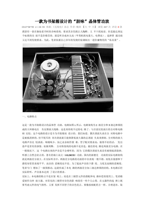
一款为书架箱设计的“胆味”晶体管功放2010-06-30 14:25:38 来源:《无线电》杂志作者:魏涛【大中小】浏览:587次评论:0条渴望有一套在独处看书时的音响系统,要求其音色既让人陶醉,又不干扰阅读。
但是能达到这个标准的功放不是价格昂贵,就是听音成本太高(甲类机耗电量大、电费高),选择普通功放又达不到发烧要求,为此,笔者依据自己多年的发烧经验调制出一道价廉物美的“私房菜”。
一、电路特点这是一款为书架箱设计的晶体管功放,电路如图1所示,电路架构为2 级差分和3级达林顿组成的大环路电压负反馈放大线路。
这是再传统不过的电路了,与目前比较流行的全对称电路相比较,这个电路的设计是专为书架箱而设计的。
我们知道,偶次谐波失真在全对称电路中是被抵消掉的,但不悦耳的奇次谐波就只能靠降低放大器的总谐波失真来抑制。
全对称的放大电路声音比较清淡,味精味少,加之业余制作困难,管子配对要求高,做得不好的话,发出恶声是常有的事情。
权衡利弊,全对称架构的电路不是首选。
最佳的电路是两级差分电路。
在一般情况下,这个电路出来的声音是不会难听的,因为它的偶次谐波失真没有被彻底消除掉,听感上自然会好点的。
著名的瑞士高文(GOLDMUND)功放、国内的新德克功放的实际电路架构就是两级差分放大。
在实际听音中,两级差分电路的功放的中音表现一般不错,而低音量感和下潜度却常常表现平平,高音的柔顺度也不佳。
为了提高声音的下潜度、力度及高频的柔顺度,笔者专门增加了一级预推动,这就形成了本电路的两级差分加三级达林顿的结构。
本电路后经实际聆听,声音基本达到了设计的要求。
实际上,本电路的特点不是在架构上,而是在三极管元件的搭配和电路补偿的使用上。
笔者酷爱制作功率放大器,对常见的三极管对音色的影响很有一些个人心得。
在元器件的选择上既要考虑元件的电气特性,又要发挥不同管子的音色优点。
要像按病配药方一样,合理进补,取长补短,最终达到音质的平衡完美。
在本功放中,输入级差分管选用的是国半的NPD5565孪生场效应管,该管子的特点是声音密度高、整齐、稳重,胆味浓,缺点是缺少灵动感,有些木讷。
Stellar Labs SLA-40 20W RMS 双通道扬声器放大器说明书

Compact Stereo Amplifier 20 Watts RMS x 2 ChannelsModel #SLA-40Stellar LabsDivision of MCM Electronics650 Congress Park DriveCenterville, Ohio 45459© 2009 MCM, a Premier Farnell CompanySafety InformationThe lightning boltwithin a triangle is intended to alert theuser to the presence of un insulated dangerous voltage levels within the product’s enclosure. This voltage may be of sufficient magnitude to constitute an electric shock risk. To reduce the risk of electricshock, do not remove coverof this device. There are nouser serviceable partsinside. Refer servicing onlyto qualified servicepersonnel.The exclamation pointwithin a triangle isintended to alert theuser to importantoperating andmaintenance(servicing)instructions in theliteratureaccompanying theappliance.Safety Precautions• Read and retain these instructions• Follow all instructions and heed warnings• Do not use this device near water• If the surface becomes dirty, clean only with dry cloth, do not use solvents or thinners• Install in accordance with the manufacturer’s instructions• Do not block ventilation openings• Do not install near heat sources such as radiators, heat registers, stoves, or other devices that produce heat• Do not defeat the safety purpose of the grounded plug. This plug has twoblades and a third ground prong. The wide blade or third prong are provided for your safety. If the provided plug does not fit into your outlet, consult anelectrician for replacement of the obsolete outlet• Protect the power cord from being stressed at the plugs, conveniencereceptacles, and where they exit the amplifier• Only use accessories specified by the manufacturer• Unplug the device during lightning storms or when unused for an extended time• Refer all servicing to qualified personnel• This device must not be exposed to water in any way. No object filled withliquids should be placed on apparatusCongratulations on your purchase of thisStellar Labs SLA Series Stereo AmplifierThis amplifier was designed specifically for use in permanent audio installations, where high reliability and premium sound quality are a must. Highly rugged construction and high efficiency design make this amplifier perfect for continuous duty applications in situations were power will be left on for indefinite periods of time.This amplifier is warranted from defects for one year from the date of purchase. Should your amplifier require service, either within or beyond that warranty period, please contact your MCM Sales Representative.This unit includes a host of features, along with an impressive list of specifications, which are detailed over the next pages. Please take the time to read this document completely prior to installation of this product. Should you have questions regarding installation or operation of this unit, please contact the MCM Technical Support Department.Features•20W RMS stereo amplifier, bridgeable to 40W RMS mono•Highly efficient design (85%)•Extreme compact size•Rugged steel housing•Independent L/R gain control•Independent bass and treble control•Switchable limiter•RCA unbalanced line level inputs•Detachable screw terminal balanced inputs, mic/line switchable•Detachable screw terminal speaker outputs•Attached brackets for easy wall mountingSpecifications•Power Output: 20W x 2 Channels, both channels driven at 8ohms•Frequency Response: 50Hz ~ 18KHz•Total Harmonic Distortion (THD): 0.05%•Power requirements: 24VDC, AC adaptor supplied•Dimensions: 2.25" (H) x 7.75" (W) x 4.5" (D)•Weight: 2 lbs.Applications•Installation behind flat panel monitors to power local speakers•Kiosk and retail displays•Powering additional zones on an existing distributed audio system•Audio program material for digital signage installations•Classroom installations, especially where video projectors are usedConnections / Controls1.DC Power Input – Supplied AC adaptor provides 24VDC, 3A with100~240VAC, 50~60Hz input range.2.Power ON/OFF Selector – Turns amplifier power on or off. When on,the blue LED immediately to the right of this switch will illuminate.3.Speaker Output Connection – Detachable Phoenix style connectorsmay be removed from the amplifier for easy access. Screw typeterminals will accept up to 14AWG wire. Note the different labeling forstereo or bridged mono connection. Also, as this is a floating output,no speaker connections may be tied to chassis or earth ground.4.Balanced Input Connection – Allows connection of line level or miclevel source to the input of the amplifier. Detachable Phoenix styleconnectors may be removed from the amplifier for easy access andaccept up to 14AWG wire. While this connection is intended forbalanced use, unbalanced sources may also be used by strapping thelow signal (-) and chassis ground terminals together.5.Unbalanced Input Connection – Accepts standard line level signalfrom conventional consumer devices such as CD/DVD players,television monitors, tape decks and tuners. Note that stereo operationrequires connection to left and right inputs. Each amplifier channelprovides two line level input connections for convenience when usingas two independent mono amplifiers.6.Mic / Line Selector – Determines whether screw terminal inputsaccept Mic level (3mV) or Line level (150mV) signal level. If you are not sure of your devices signal level, first use Line level. If signal level is very low, set the output volume to the lowest setting and select the Mic position. Then slowly increase the Channel Level Controls.7.Left / Right Channel Level Controls – Independent controls setoutput level for the amplifier. When the amplifier is operating inbridged mono mode, only the right control is used.8.Bridged / Stereo Mode Selector – Allows the unit to operate as astereo amplifier, with two channels each capable of 20W RMS output, or as a single mono amplifier channel, with 40W RMS output.9.Limiter ON/OFF Selector – Engages or disengages the input signallimiter circuit for amplifier output protection. In the ON position, the amplifier will automatically limit high input signal levels, which willprevent the amplifier from distorting, and reduce potential harm to speakers. In the OFF position, the amplifier operates in normal mode.It should be noted that overall dynamic range will be reduced when the limiter is ON, thus being the tradeoff that occurs when this feature is utilized.10.Bass Control – This control adjusts low frequencies centered at100Hz, at a rate of ±10dB.11.Treble Control – This control adjusts high frequencies centered at10,000Hz, at a rate of ±10dB.MCM Custom Audio and Stellar Labs products are warranted, by MCM Electronics, against manufacturer defects for a period of one year from the original date of purchase. This warranty is limited to manufacturer defects, in either materials or workmanship. MCM Electronics, or any other worldwide divisions of Premier Farnell PLC, are not responsible for any consequential or inconsequential damage to any other component, structure or the cost of installation or removal of said items.For questions or specific information regarding warranty replacement or repair, contact:MCM Electronics800-543-4330。
PCM3168A中文资料

• EXTERNAL RESET PIN: – ADC/DAC Simultaneous
• AUDIO INTERFACE MODE: – ADC/DAC Independent Master/Slave
• AUDIO DATA FORMAT: – ADC/DAC Independent I2S™, Left-Justified, Right-Justified, DSP, TDM
• POWER SUPPLIES: 5 V for Analog and 3.3 V for Digital
Copyright © 2008, Texas Instruments Incorporated
元器件交PC易M3网 PCM3168A-Q1
SBAS452 – SEPTEMBER 2008 .........................................................................................................................................................................................
• PACKAGE: HTQFP-64 • OPERATING TEMPERATURE RANGE:
– Consumer Grade: –40°C to +85°C – Automotive Audio Grade: –40°C to +105°C
智能化5.8GHz双向功率放大器的设计

通路动态范围高达100dBm。
发射通路主要由驱动级功放、
主功放和自动功率电平控制模块构
成,对需要发射的信号进行增益调
节,使双向放大器的发射信号稳定 图1 智能化5.8GHz双向功率放大器的结构框图
2011.11
7319
Copyright©博看网 . All Rights Reserved.
次增益控制的结果进行修证,以确保 输出功率的精度。
系统设计方案 本文设计的智能化5.8GHz双向功
率放大器系统构架如图1所示,主要 由电源模块、接收通道、接收通路、 开关控制、自动功率控制等模块构
在某个功率水平,输出信号功率大小 可根据应用要求进行调节。图3所示 是发射通道的电平图,可见自动增益 调节范围可达15dB~35dB,能够处 理-3dBm~17 dBm的信号,可方便地
关键模块设计 大动态范围接收通路的设计 接收通路的动态范围很大程度上
都取决于低噪声放大器的噪声性能和
成。
接收通路采用了LNA、数控衰减
器和增益模块级联的方案,有效提高
接收灵敏度的同时扩展了动态范围。
图2所示是接收通道的电平图。P 1dB表 示接收通路能够处理的最大功率信
号;P max表示能够处理的最大线性功 率,P min表示接收机能够处理的最小 信号,由图可以看出本次设计的接收
责任编辑:王莹
表1 HSMS2850的检波输出电压和输入功
其中BW 为接收机带宽,
率的关系
P in (dBm)
-22 -19 -16 -13 -12 -11 -10 -9 -8 -7 -6
V out (V)
7 12 20 41 52 55 66 77 89 115 120
P in (dBm)
KT0612音频接收芯片

Applications
Wireless Microphone, DVD player, Blue ray player, Set-top Box, Portable Device, Wireless Speaker
Rev.1.2
Information furnished by KT Micro is believed to be accurate and reliable. However, no responsibility is assumed by KT Micro for its use, nor for any infringements of patents or other rights of third parties which may result from its use. No license is granted by implication or otherwise under any patent or patent rights of Beijing KT Micro, Ltd.
RFINP LNA RFINN ADC AOUTP Audio DAC AOUTN
DSP Based FM demodulator & Audio processor
ADC
SCL I2C Master SDA Regulator Crystal
VDDVSSXI NhomakorabeaXO
KT0612 System Diagram
Description
The KT0612 is the VHF band chip of our full suite of the revolutionary wireless microphone chips, KT06xx, which replace hundreds of discrete components in a wireless microphone system while keeping the high standard of sound quality and functionality. The KT0612 is a VHF band receiver that includes audio amplifier, de-emphasis, expander, LO synthesizer and audio DAC. It is designed to process the modulated FM signal in VHF band and demodulate it into audio signal. The KT0612 only requires a single low-voltage supply thanks to a built-in regulator. For an audio transmission system built with a KT0612, no external tuning is required, which makes design-in effort minimum. The KT0612 provides direct and simple interface to support mechanical tuning. A pre-programmed low cost EEPROM can be used to configure the radio settings to differentiate product designs and accommodate standards in various regions. No external MCU is required. It is packaged in generic QFN24.
DAC关键技术

DAC关键技术我们现在就来看看几个比较著名的DAC芯片的数字滤波器性能,以对他们进行评估。
评价数字滤波器的性能,可以简单从两个参数考虑,一个是Passband Ripple 另一个是Stopband Attenuation 。
芯片 Passband Ripple(DB) Stopband Attenuation(DB)--------------------------------------------------------------WM8741 0.00005 110PCM1792 0.00001 130PCM1794 0.00001 130AD1955 0.0002 110AD1852 0.0002 110AD1853 0.0002 110CS4328 0.00025 90CS43112 0.0001 102CS4398 手册未直接给 102PCM2702 0.002 82PCM1793 0.002 82WM8740 0.001 82TDA1305 0.025 60PCM2704 0.04 50从上面的数据来看WM8741和PCM1792/PCM1794是极品DAC芯片,AD1955把守第二梯队(CS43122/CS4328已停产),但是AD1955有个特点就是可以外接更好的数字滤波器提升性能。
CS4328是个很老的芯片了,但是性能却非常棒,而且电路简单,缺点是难以买到,另外就是只支持到48K采样。
代表作是Meridian英国之宝的563解码器。
第三梯队中PCM2702是个好东西,可以说,如果用了它,可以抵PCM1793和WM8740这个档次的DAC了,所以,如果是PCM2704加上PCM1793或者WM8740,性能和PCM2702差不多。
最后是PCM2704/5/6/7,本身自带的数字滤波器性能比较差,如果配一块PCM1793/WM8740还不如直接上PCM2702(不过据说PCM2702非常难处理,很容易死机,这是限制它应用的最主要原因吧),所以最好是搭配AD1955这个档次的,以作较大提升。
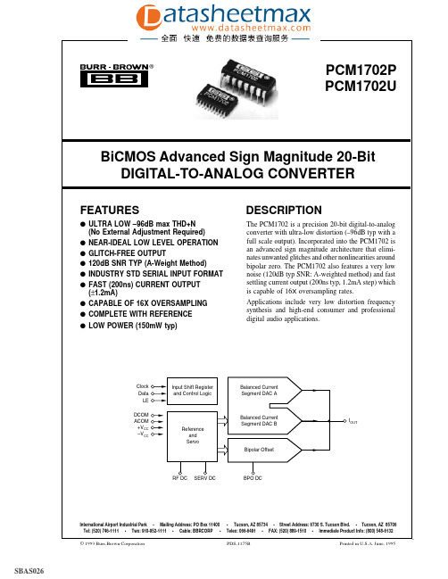
IC datasheet pdf-PCM1702,PDF(BiCMOS Advanced Sign Magnitude 20-Bit D_A Converter )
Logic Level: VIH VIL IIH IIL
Data Format
Input Clock Frequency
VIH = +VDD VIL = 0V
TTL/CMOS Compatible
+2.4 0
+VDD 0.8
±10
±10
Serial, MSB First, BTC(1)
±1.2
mA
1.0
kΩ
(±0.003% of FSR, 1.2mA Step)
200
ns
No Glitch Around Zero
POWER SUPPLY REQUIREMENTS
Supply Voltage Range: +VCC = +VDD
–V = –V
CC
DD
Combined Supply Current: +ICC
PCM1702P/U, -J, -K
PARAMETER
CONDITIONS
MIN
TYP
MAX
UNITS
RESOLUTION
20
Bits
DYNAMIC RANGE, THD + N at –60dB Referred to Full Scale, with A-weight
110
dB
DIGITAL INPUT
®
49%
FPO
PCM1702P PCM1702U
BiCMOS Advanced Sign Magnitude 20-Bit DIGITAL-TO-ANALOG CONVERTER
FEATURES
q ULTRA LOW –96dB max THD+N (No External Adjustment Required)
PCM1802中文资料
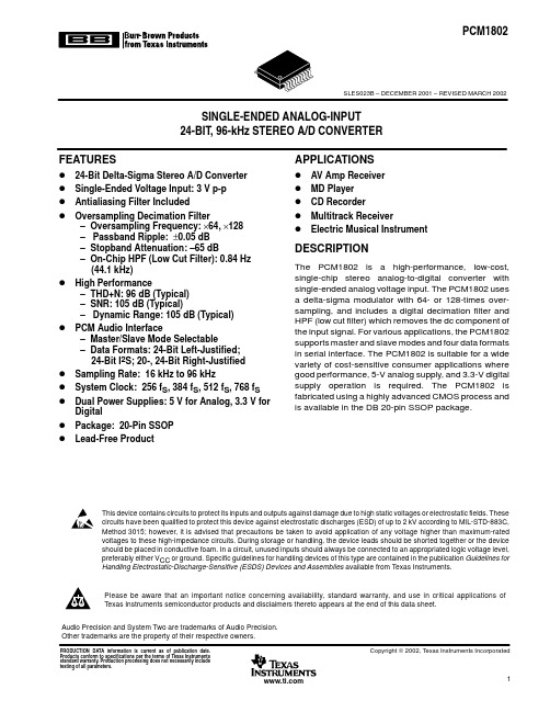
VINL
BCK LRCK FSYNC DOUT Mode/ Format Control
VREF1 Reference VREF2
FMT0 FMT1 MODE0 MODE1 BYPAS-End /Differential Converter
Power Supply
pcm1802 burrbrownproducts from texas instruments 1020 19 18 17 16 15 14 13 12 11 ccagnd pdwn bypas fsync lrck mode1 mode0 fmt1 fmt0 osr scki dddgnd dout bck pcm1802 (top view) p0009-02 single-end /differential converter bck referencesingle-end /differential converter thorder delta-sigma modulator thorder delta-sigma modulator 1/64 (1/128) decimation filter high-passfilter power supply agnd dddgnd clock timingcontrol serial interface mode/ format control lrck fsync dout fmt0 fmt1 mode0 mode1 bypas osr pdwn scki b0004-07 200150 100 50 1624 32 40 48 56 64 oversampling ratio g001frequency 200150 100 50 1624 32 oversamplingratio y64g002 frequency 10090 80 70 60 50 40 30 20 10 0.000.25 0.50 0.75 1.00 oversamplingratio y64g003 frequency 1.00.8 0.6 0.4 0.2 0.0 0.2 0.0 0.1 0.2 0.3 0.4 0.5 0.6 oversamplingratio y64g004 /1000]1.0 0.8 0.6 0.4 0.2 0.0 0.2 g006frequency /1000]100 90 80 70 60 50 40 30 20 10 0.00.1 0.2 0.3 0.4 1.00.9 0.8 0.7 0.6 0.5 0.4 0.3 0.2 0.1 0.0 10100 100k 1k 10k g008 50 45 40 35 30 25 20 15 10 1001k
PCM1801中文资料

®
PCM1801
2
元器件交易网
PIN CONFIGURATION
Top View
SOIC
1 VINL
VREF1 14
2 VINR
VREF2 13
3 DGND
AGND 12
4 VDD
PCM1801U
VCC 11
5 SCKI
FMT 10
6 BCK
BYPAS 9
7 LRCK
DOUT 8
DC ACCURACY Gain Mismatch Channel-to-Channel Gain Error Gain Drift Bipolar Zero Error Bipolar Zero Drift
IOH = –1.6mA IOL = +3.2mA
256fS 384fS 512fS
High-Pass Filter Bypass High-Pass Filter Bypass
PIN ASSIGNMENTS
PIN NAME I/O DESCRIPTION
1
VINL
IN Analog Input, Lch.
2
VINR
IN Analog Input, Rch.
3
DGND — Digital Ground
4
VDD
— Digital Power Supply
5
SCKI
IN System Clock Input; 256fS, 384fS, or 512fS.
FS (VIN = 0dB) –3dB
2.828 2.1 30 170
Vp-p V kΩ
kHz
DIGITAL FILTER PERFORMANCE Passband Stopband Passband Ripple Stopband Attenuation Delay Time (Latency) High Pass Frequency Response
PCM1780资料

PARAMETER
TEST CONDITIONS
MIN
TYP MAX UNIT
Resolution
24
Bits
DATA FORMAT
PCM1780, Audio data interface format PCM1782
PCM1781
Right-justified, I2S, left-justified
Left-Justified – Digital Attenuation: Mode Selectable
• 0 dB to –63 dB, 0.5 dB/step • 0 dB to –100 dB, 1 dB/step – Digital De-Emphasis – Digital Filter Rolloff: Sharp or Slow – Soft Mute – Zero Flags for Each Output – Open-Drain Output Zero Flag (PCM1782) • Hardware Control (PCM1781): – I2S and 16-Bit Word, Right-Justified – Digital De-Emphasis
Analog output load resistance Analog output load capacitance Digital output load capacitance Operating free-air temperature, TA
System clock Sampling clock
I2S, right-justified
Audio data bit length
System Two, Audio Precision are trademarks of Audio Precision, Inc. All trademarks are the property of their respective owners.
16位ADC芯片pcm1801市场分析报告
16位音频ADC芯片MXT401市场分析单位部门:市场部项目设计:王宗民联系人:张宏伟填报日期:2006年4月16日地址及邮编:北京市丰台区东高地四营门北路2号 10007616位音频ADC芯片MXT1801市场分析 (1)(一)芯片简介 (3)MXT1801芯片说明 (3)MXT1801特点 (3)(二)市场分析 (4)(1)音频16位ADC市场分析 (4)(2)音频24位ADC市场分析 (4)(3)MXT1801市场容量和销售预测 (5)(4)MXT1801芯片的生命周期 (5)(5)MXT1801芯片的投资回报 (6)(三)音频ADC MXT1801芯片竞争对手分析 (6)(1)国内竞争对手(无) (6)(2)国外竞争对手(3家) (6)(四)遇到的问题 (8)(五)目前我们的工作进展 (8)(六)我们的下一步工作计划 (8)(一)芯片简介MXT1801芯片说明TI公司的PCM1801芯片是一颗全差分模拟输入16Bit位 48KHz立体声模/数转换芯片(ADC),它的动态范围可以达到98分贝,信噪比93分贝,THD+N: -88 dB,5V工作电压,48KHz的采样率。
我们公司的MXT1801芯片完全兼容和可替代TI的PCM1801,MXT1801芯片是一个立体声16位可调节取样率ADC芯片,它可从双麦克风输入DVR、高品质的数字语音设备提供高质量录音功能。
並支持从 4 kHz到 48 kHz ADC的取样率。
输出音量控制调节范围为0 dB 到 -95 dB,间距为 0.75 dB。
至于麦克风输入,输入音量控制调节范围为0 dB 到 22.5 dB,间距为1.5 dB。
MXT1801主要用来支持2通道音频。
该产品是视频监控系统、家庭影院、DVR、AVR、卡拉OK机、迷你组合、多合一立体声系统、以及机顶盒应用的理想选择。
MXT1801特点•采用高性能∑△技术•带有独立音量控制的2通道•同时调节所有DAC的主音量控制•AudioUltra™ +3dBV 输出模式 SNR 93dB•ADC THD+N -88dB• 4 kHz ,16kHz ,32 kHz, 44.1 kHz, 48kHz ADC取样率•带有独立音量控制的双麦克风输入•差分立体声模拟输入•针对电子音频的多格式Multi-format I2S 串行接口•数字去加重功能•14引脚 SSOP 小封装•节电低功耗模式•5V工作电压(二)市场分析(1)音频16位ADC市场分析音频16位ADC主要应用在工业音视频领域,工业领域对音频的品质要球不高,对ADC高性能要求低,但对稳定性和可靠性有较严格的要求。
Yamaha音频Receiver 7.2ch 直流能量型 140W ch 6ohms 80W ch

Amplification›Channels: 7›Amplification Type: Direct Energy›140 W/ch (6 ohms, 1 kHz, THD 0.9 %, 1ch Driven FTC)›80 W/ch (8 ohms, 20 Hz-20 kHz, THD 0.08 %, 2ch Driven FTC) Audio Features›Dolby Atmos/Dolby Surround›DTS:X Ready*1/DTS Neural:X*1›Reflex Optimizer›Dolby® TrueHD/Dolby Digital Plus›DTS-HD Master Audio/DTS-HD High Resolution Audio/DTS 96/24/DTS-ES/ DTS-HD Express›DSD Playback via Network/USB (5.6 MHz/2ch 2.8 MHz/2ch)›DSD Disc (SACD) Playback via HDMI (2.8 MHz/5.1ch, 2ch)›Digital Core Engine with Cirrus Logic (Quad Core) x1›384 kHz/32-bit DAC (AK4458)›HDMI Audio Return Channel (ARC)›MCACC Auto Room Tuning• Phase Control• Subwoofer EQ (4 Band)›Advanced Sound Retriever (2ch)›Advanced Surround Modes• Classical, Unplugged, Entertainment Show, Drama, AdvancedGame, Action, Rock/Pop, Sports, Extended Stereo, Extended Mono,Front Stage Surround, Auto SurroundVideo Features›Ultra HD Pass-through with HDCP 2.2 (4K/60p/4:4:4/24-bit,4K/24p/4:4:4/36-bit, 4K/60p/4:2:0/36-bit)›HDR and BT.2020 Support›Ultra HD Upscaling (1080p 4K)›3D Ready (Blu-ray Disc™, Broadcast, and Games)›Deep Color (36-bit), “x.v.Color”Home Network Features›Google Cast*1*2›Apple AirPlay Certified›Pandora®*3›Spotify® Digital Music-Streaming Service Ready*4›Internet Radio with TuneIn®›TIDAL Music Streaming Service Ready*1›DEEZER*1*5›FireConnect™ powered by Blackfire Research*1*6›Hi-Res Audio File Playback via USB/Wired Network• Up to 192 kHz/24-bit ALAC, AIFF, FLAC, WAV• 5.6/2.8 MHz DSD Playback• Dolby® TrueHD Playback (USB only) Convenience Features›Built-in Wi-Fi® (Dual Band 5 GHz/2.4 GHz)›Built-in Bluetooth® Wireless Technology (Version: 4.1, Profile: A2DP/ AVRCP, Codec: SBC/AAC)›iControlAV5 Remote Control App Ready (iOS/Android)*7›New GUI with System/Network Setup Menu›Auto Power Off in HDMI Standby Through›AM/FM Tuner 40 Presets›Sleep Timer›User-Friendly Simple Remote ControlThe Elite®VSX-LX101 is fully-equipped for the latest multi-dimensional surround sound formats, DTS:X®Ready*1and Dolby Atmos®, featuring the Reflex Optimizer for enabled speaker calibration. With Ultra HD (4K/60p/4:4:4) upscaling and pass-through and support for the latest video standards HDR and BT.2020, images are ever more impressive. In addition to internet radio and various network streaming services, with Google Cast™*1*2 built-in you can use your mobile device to cast your favorite music to your receiver.*1 Available with firmware update *2 Compatible apps required *3 Service only available in the U.S., Australia, and New Zealand*4 For service availability in your country, check *5 Service available in Canada, not available in the U.S. *6Optional future 2016 Pioneer Wireless Speaker required*7Available for free download from the App Store SM/the Google Play™Control4 and the Control4 logo are registered trademarks of Control4 Corporation.Crestron and the Crestron logo are registered trademark of Crestron Electronics, Inc.AMX a nd t he A MX l ogo re t rademarks o f A egistered i n t he U .S. a nd Universal R emote C ontrol l ogo i s a r egistered o f U niversal R emote RTI logo is a registered trademark of Remote Technologies Incorporated.Savant Logo is a registered trademark of Savant Systems, LLC.© 2016 Onkyo & Pioneer Corporation. All rights reserved.Note: Specifications and design subject to change without notice.•PIONEER, ELITE, MCACC, Phase Control, Advanced Sound Retriever, and the logos are registered trademarks of Pioneer Corporation, and are used under license. •The terms HDMI and HDMI High-Definition Multimedia Interface, and the HDMI Logo are trademarks or registered trademarks of HDMI Licensing LLC in the United States and other countries. •Dolby, Dolby Atmos, and the double-D symbol are reg-istered trademarks of Dolby Laboratories. For DTS patents, see . Manufactured under license from DTS, Inc. DTS, the Symbol, DTS in combination with the Symbol, DTS:X, and the DTS:X logo are registered trademarks or trademarks of DTS, Inc. in the United States and/or other countries. © DTS, Inc. All Rights Reserved. •“Made for iPod”, “Made for iPhone” and “Made for iPad” mean that an electronic accessory has been designed to connect specifically to iPod, iPhone, or iPad, respectively, and has been certified by the developer to meet Apple performance standards. Apple is not responsible for the operation of this device or its compliance with safety and regulatory standards. Please note that the use of this accessory with iPod, iPhone, or iPad may affect wireless performance. •AirPlay works with iPhone, iPad, and iPod touch with iOS 4.3.3 or later, Mac with OS X Mountain Lion, and Mac and PC with iTunes 10.2.2 or later. The AirPlay logo is a trademark of Apple Inc. App Store is a service mark of Apple Inc. •iOS is a trademark on which Cisco holds the trademark right in the US and certain other countries. •Wi-Fi is a registered trademark of the Wi-Fi Alliance. The Wi-Fi CERTIFIED Logo is a certification mark of the Wi-Fi Alliance. •The Bluetooth word mark and logos are registered trademarks owned by Bluetooth SIG, Inc. •”x.v.Color” is a trademark of Sony Corporation. •Pandora, the Pandora logo, and the Pandora trade dress are trademarks or registered trademarks of Pandora Media, Inc. used with permission. •Spotify and the Spotify logo are trademarks of the Spotify Group, registered in the U.S. and other countries. • FireConnect is a technology of Blackfire Research Corp, USA. • FireConnect and the FireConnect logo are trademarks of Blackfire Research. •The product with the Hi-Res Audio logo is conformed to Hi-Res Audio standard defined by Japan Audio Society. The logo is used under license from Japan Audio Society. •Android, Google Play, Google Cast and the Google Cast badge are trademarks of Google Inc. •Blu-ray Disc™, Blu-ray™, Ultra HD Blu-ray™ and the logos are trademarks of the Blu-ray Disc Association.Integrated TechnologiesAll other trademarks and registered trademarks are the property of their respective holders.Front Terminals›USB 1 In for USB Drive ›MCACC Setup MIC In›Audio 1 In (Mini Stereo Jack)›Phones 1 OutRear Terminals›HDMI 6 In (4 Assignable) ›HDMI 1 Out›Ethernet 1 In›AV (Composite) 2 In (Assignable) ›Phono (MM) 1 In›Digital Coaxial 1 In (Assignable) ›Digital Optical 1 In (Assignable) ›Subwoofer 2 Pre Out›Speaker 7 ch Out (FRONT, CENTER, SURROUND, SURROUND BACK/HEIGHT/ Bi-AMP)›FM/AM AntennaSpecifications›Power Requirements: AC 120 V, 60 Hz ›Power Consumption/Standby: 460 W/0.1 W›Dimensions (W x H x D): 17-1/8 x 6-13/16 x 14-9/16 inches (435 x 173 x 370.5 mm) ›Weight: 19.8 lbs. (9 kg)UPC›889951000051。
南京聚科光电 单频激光器噪声测试仪 N1801A 产品手册说明书
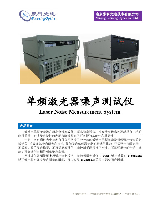
单频激光器噪声测试仪
Laser Noise Measurement System
低噪声单频激光器在超高分辨率成像、超高速率通信、超高精度传感等领域具有广泛的应用前景,对其噪声特性的表征与测试具有不可忽视的基础性和重要性。
为此,南京聚科光电技术有限公司研发了一种新的低噪声单频激光器相频噪声特性的测试设备,该设备基于自研专利技术,使低噪声单频激光器的测试简化为:只需要一台激光器,不需要先验的噪声模型,不再需要额外的主动控制手段保持正交性,不需要很长的光纤,就能完整测试所有相位频率噪声参量。
同时该仪器还使用多级噪声控制技术,突破频谱分析仪约30dB 噪声系数对-143dBc/Hz 以下激光相对强度噪声测量的限制,可以实现-158dBc/Hz 的相对强度噪声测量。
产品简介
●
可以进行单频激光器相频特性所有参数的完整测试及其物理意义的完整解读:包括RIN 、频率/相位噪声、频率/相位噪声功率谱密度、不同测量时间下的线宽等。
● 超低噪声 ● 全自动
● 无需低噪声参考源
●
测试仪自带的4通道、16bits 的ADC 可以用作高精度示波器
可用于光传感、光通信、光探测等领域的各类激光光源噪声特性的测试与表征。
技术指标
应用领域 产品特性
典型测试结果。
喷泉音响系统使用操作和维护

喷泉音响系统使用操作和维护音响系统是音乐景观的重要组成部分之一。
要据水体景观规模和布局中、观赏面特点以及户外扩声要求,户外扩声音箱呈点阵布局。
即共布置4组音箱,两组主扩声音箱、两组补声音箱。
采用立柱吊柱式安装。
四组音箱平面投影连线呈梯形,主扩声音箱位于“梯形”的长边(离景观型面近),补声音箱位于“梯形”的短边。
声音均匀分布,在主观赏面的空间内有足够的声压级。
音频系统全数字化音频控制处理,全天候使用。
1、主要设备配置及性能简介1.1扬声器系统扬声器选用美国Community Entasys 高性能柱状线阵音箱,该音箱为三分频音箱。
主扩声系统两组,每组由2只全频音箱和1只低频音箱串接而成,另加1只号角式的超低音音箱。
补声系统两组,每组由1只全频音箱和1只低频音箱串接而成,另加一只号角式的超低音音箱。
(1)、 Entasys全频音柱型号:ENT-FR;主要性能、参数:驱动单元组件:低频驱动3.5"6个钕质低音喇叭;中频驱动2.35"18个;高频驱动1"*1"42个;频率响应:200HZ-20KHZ;声音覆盖范围:水平指向120°,垂直指向6-12°可调;功率:额定功率600W,节目功率1500W,峰值功率3000W;阻抗12Ω,灵敏度104dB;重量17.4kg。
(2)、 Entasys低频音柱型号:ENT-LF ;主要性能、参数:驱动单元组件:6个3.5"钕制驱动器;频率响应:200HZ-1KHZ;声音指向:在低频范围内扩大垂直指向性;阻抗12Ω,最大声压级110dB;重量:10.9kg。
(3)、防雨超低音音箱型号、规格:ZS-218,全天候超低频扬声器。
主要性能、参数:频率响应(-3dB):35HZ-1.8KHZ;功率:1600WRNS/6400WPEAK;阻抗:4Ω;灵敏度(dB/1M/1W):102dB;净尺寸(W*H*D)1075*567*768; 重量85kg。
最常用芯片

器件型号封装数量功能备注运放THS3115ID SOIC-14 1具有关断状态的双路低噪声高输出电流的110MHz 放大器电源:±5V-±15V输出电流:150mA OPA2691 SOIC-14 3具有禁用功能的双路宽带电流反馈运算放大器高速放大器(大于等于50MHz)THS3115ID SOIC-14 2具有关断状态的双路低噪声高输出电流的110MHz 放大器电流反馈AD811 DIP-8 2TLC27L2ACD SOIC-8 2LinCMOS(TM) 精密双路运算放大器低功耗OPA209 SOIC-8 1单通道2.2nV/rtHz、18MHz、36V RRO 精密运算放大器电源:±2.25V to±18V, +4.5V to+36V OPA2209 SOIC-8 7双通道,其他同OPA209OPA699 SOIC-8 2宽带高增益限压放大器带宽积1000M;G=6,-3dB,BW=260M;SR=1400V/us电源:±5V SN10502 SOIC-8 2双路低失真高速轨至轨输出运算放大器;BW=100M(-3dB,G=2);SR=500V/us;电源:3V-15V MAX4477 SOIC-8 2低噪声、低失真、宽带、满摆幅运算放大器电源:2.7V-5.5VGBW=10M AD603 SOIC-8 4低噪声、90 MHz可变增益放大器AD603 DIP-8 4INA103 SOL-16 1低噪声低失真仪表放大器,GBW=100M(G=1000)内置增益设置电阻:G=1,100电源:±9V/±25 OPA4830 TSSOP-14 1低功耗宽带放大器280MHz (G = +1)120MHz (G = +2)双电源:1.4V to ±5.5V单电源:+2.8V to +11VOPA2340PA DIP-8 3 单电源轨至轨运算放大器带宽: 5.5MHzTLC2262CD SOIC-8 4双路高级LinCMOS(TM) 轨至轨运算放大器低噪声PGA103U SOIC-8 3 可编程增益放大器NE5532DR SOIC-8 8 双路低噪声高速音频运算放大器OPA4354AIPWT SSOP-14 2 250MHz 轨至轨I/O CMOS 四路运算放大器OPA642 SOIC-8 1 单路宽带低失真放大器;GBW = 400M电源:±6.5VSN761666DGKR MSOP- 8 2 AGC 放大器Input Frequency(MHz)30 to 70LF353 DIP-8 1 宽带放大器,增益带宽积:3MHz双电源电压:±5,±9, ±12, ±15VMAX419EPD DIP-14 1 转换速率0.08V/us,增益带宽积150kHzLF411CN SOP-8 1 低偏置、低漂移JFET输入运算放大器线性运算放大器OP070 SOIC-8 4 低噪声JFET 输入解补偿运算放大器标准线性放大器TLV2472 DIP-8 1 双路低功耗轨至轨输入/输出运算放大器低噪声MAX414BCPD DIP-14 2 28M单位增益带宽低电源电压±2.4伏特到±5 VMAX9939 µMAX-10 1 MAX9939为通用、差分输入可编程增益放大器(PGA),可理想动态变化范围较宽的信号调理超低增益温漂OPA2544T TO-220-11 2 增益带宽积1.4MHz,转换速率8 V/µs单路/双路(±)±10 V ~ 35 VSA7454C DIP-18 5 双通道AB类音频功率放大器D类功放SD7408 Hsop-28-375-0.8 72×10W模拟输入的D类音频功放TPA3123D2PWP SSOP-24 4具有SE 输出的25W 立体声D 类音频功率放大器乘法器AD835 SOIP-8 1AD835是一款完整的四象限电压输出模拟乘法器,采用先进的介质隔离互补双极性工艺制造。
Y220S用户指南_Y220-T10_01_中文_中国移动

3. 通话功能...................................................................... 16
3.1 拨打电话 .............................................................................. 16 3.2 接听或拒接电话 ................................................................... 17 3.3 通话中的其他操作 ................................................................ 18 3.4 使用通话记录 ....................................................................... 19 3.5 使用飞行模式 ....................................................................... 19
4. 联系人 ......................................................................... 20
4.1 打开通讯录 .......................................................................... 20 4.2 从 USIM 卡或 SIM 卡复制联系人信息 .................................. 20 4.3 创建联系人信息 ................................................................... 20
基于SimpliciTI网络协议的无线温度采集系统

基于SimpliciTI网络协议的无线温度采集系统
王昕玮
【期刊名称】《科技创新与应用》
【年(卷),期】2017(000)018
【摘要】文章基于SimpliciTI网络协议设计一种低功耗无线温度采集系统.本系统硬件采用低功耗单片机MSP430F5308和射频芯片CC1101组成无线通讯模块,温度采集模块使用MCP9808数字温度传感器芯片.本系统具有低功耗,方便移动,组网灵活,测量精度高,不受环境限制等优点.
【总页数】1页(P63)
【作者】王昕玮
【作者单位】江苏省紫光智能系统有限公司北京科技分公司,北京100011
【正文语种】中文
【相关文献】
1.基于SimpliciTI协议的无线温度采集系统的设计与实现
2.基于Android系统与单片机的无线蓝牙温度采集系统
3.SimpliciTI网络协议的无线数据采集系统设计
4.基于嵌入式系统火炉温度的远程无线采集系统
5.基于Android系统与单片机的无线蓝牙温度采集系统
因版权原因,仅展示原文概要,查看原文内容请购买。
X-618广播产品性能参数表..
X-618广播产品性能参数表..---------------------------------------目录一、分布式智能系统控制器X-DCS2000 (2)二、高效数字功率放大器X-DA1500 (3)三、高效数字功率放大器X-DA2250 (4)四、高效数字功率放大器X-DA4125 (4)五、音源前置放大器X-MAP04 (5)六、网络资源整合模块X-NRI (6)七、自定义网络寻呼控制台X-NPMI (7)八、中小项目系统管理软件包X-SPT900 (8)九、电源时序器(16路)AS-3228S (9)十、天花扬声器LM2-PCP06B (10)十一、天花扬声器L-PCP20A (11)十二、壁挂扬声器L-PWP06A (11)十三、音量控制器HN-VC30 (12)一、分布式智能系统控制器X-DCS2000?支持手动选择音源和分区按钮,可直接进行操作;?支持应急话筒,用于消防广播;?不同的指示灯标识系统运行状态;?可通过自定义网络寻呼控制台NPM进行远程寻呼和广播操作;?8个分区输出,可通过软件配置;?具有4路辅助输入,用于连接外接音源设备;?具有4路自动音量控制输入,可设置每路音频输入的幻象电源和增益;?自动检测分区短路、开路故障;?保险管保护主电源,当DCS内部的电源短路时,自动断开主电源供电;?支持分区监听和音源监听,当系统通过网络扩展时,可进行网络监听;?内置1G Flash卡和2G SD卡,可存储语音文件,实现语音信息播放、语音合成等功能;?支持同时播放四种语音信息或网络音频;?支持自动记录操作日志和故障日志,每一种最多存储10000条;?支持主备功放切换,可任意配置备用方式;?自检功能;?支持自动故障诊断;?可调节广播音量;?可以自定义按钮开关和组合按钮功能。
并能安装按钮功能描述标签;?具有矩阵功能,可实现在任意分区播放任意音源;?可根据需要设置消防广播模式,提高紧急情况下人员疏散效率;?支持定时对指定区域播放指定的声音,实现无人值守功能;?可通过以太网进行系统扩展。
- 1、下载文档前请自行甄别文档内容的完整性,平台不提供额外的编辑、内容补充、找答案等附加服务。
- 2、"仅部分预览"的文档,不可在线预览部分如存在完整性等问题,可反馈申请退款(可完整预览的文档不适用该条件!)。
- 3、如文档侵犯您的权益,请联系客服反馈,我们会尽快为您处理(人工客服工作时间:9:00-18:30)。
BurrĆBrown Productsfrom TexasInstrumentsFEATURES APPLICATIONSDESCRIPTIONBCK V IN LV REF1V REF2V IN RAGNDV CC V DDDGNDLRCKDOUTFMTBYPASSCKIB0004-02PCM1801SBAS131C–OCTOBER2000–REVISED JULY2007 SINGLE-ENDED ANALOG-INPUT16-BIT STEREO ANALOG-TO-DIGITAL CONVERTER•DVD Recorders•Dual16-Bit MonolithicΔΣADC•DVD Receivers•Single-Ended Voltage Input•AV Amplifier Receivers•Antialiasing Filter Included•Electric Musical Instruments•64×Oversampling Decimation Filter:Pass-Band Ripple:±0.05dBStop-Band Attenuation:–65dBThe PCM1801is a low-cost,single-chip stereo •Analog Performance:analog-to-digital converter(ADC)with single-ended THD+N:–88dB(typical)analog voltage inputs.The PCM1801uses a SNR:93dB(typical)delta-sigma modulator with64times oversampling,a Dynamic Range:93dB(typical)digital decimation filter,and a serial interface that Internal High-Pass Filtersupports slave mode operation and two data formats.•PCM Audio Interface:Left-Justified,I2S The PCM1801is suitable for a wide variety ofcost-sensitive consumer applications where good •Sampling Rate:4kHz to48kHzperformance is required.•System Clock:256f S,384f S,or512f S•Single5-V Power Supply•Small SO-14PackagePlease be aware that an important notice concerning availability,standard warranty,and use in critical applications of TexasInstruments semiconductor products and disclaimers thereto appears at the end of this data sheet.System Two,Audio Precision are trademarks of Audio Precision,Inc.All other trademarks are the property of their respective owners.PRODUCTION DATA information is current as of publication date.Copyright©2000–2007,Texas Instruments Incorporated Products conform to specifications per the terms of the TexasInstruments standard warranty.Production processing does notnecessarily include testing of all parameters.ABSOLUTE MAXIMUM RATINGSRECOMMENDED OPERATING CONDITIONSPCM1801SBAS131C–OCTOBER 2000–REVISED JULY 2007This integrated circuit can be damaged by ESD.Texas Instruments recommends that all integrated circuits be handled with appropriate precautions.Failure to observe proper handling and installation procedures can cause damage.ESD damage can range from subtle performance degradation to complete device failure.Precision integrated circuits may be more susceptible to damage because very small parametric changes could cause the device not to meet its published specifications.PACKAGE/ORDERING INFORMATIONPRODUCTPACKAGE PACKAGE PACKAGE ORDERING TRANSPORT QUANTITYTYPE CODEMARKING NUMBER MEDIAPCM1801U Rails 56PCM1801U14-pin SOICDPCM1801UPCM1801U/2KTape and reel2000Supply voltage:V DD ,V CC–0.3V to 6.5VSupply voltage differences:V DD ,V CC ±0.1V GND voltage differences:AGND,DGND ±0.1VDigital input voltage –0.3V to (V DD +0.3V),<6.5V Analog input voltage–0.3V to (V CC +0.3V),<6.5VInput current (any pin except supplies)±10mA Power dissipation300mW Operating temperature range –25°C to 85°C Storage temperature –55°C to 125°CLead temperature,soldering260°C,5sPackage temperature (IR reflow,peak)235°Cover operating free-air temperature rangeMINNOMMAX UNIT Analog supply voltage,V CC 4.55 5.5V Digital supply voltage,V DD4.55 5.5V Analog input voltage,full-scale (–0dB) 2.828Vp-pDigital input logic family TTLSystem clock 8.19224.576MHz Digital input clock frequency Sampling clock3248kHz Digital output load capacitance 10pF Operating free-air temperature,T A–2585°C2Submit Documentation Feedback1234 567141312111098V REF 1V REF 2AGND V CC FMT BYPAS DOUTPCM1801(TOP VIEW)P0005-01V IN L V IN R DGND V DD SCKI BCK LRCKPCM1801SBAS131C–OCTOBER 2000–REVISED JULY 2007PIN CONFIGURATIONTable 1.PIN ASSIGNMENTSNAME PIN I/O DESCRIPTIONAGND 12–Analog ground BCK 6I Bit clock input BYPAS 9I HPF bypass control (1)L:HPF enabled H:HPF disabledDGND 3–Digital ground DOUT 8O Audio data output FMT 10I Audio data format (1)L:MSB-first,left-justified H:MSB-first,I 2S LRCK 7I Sampling clock inputSCKI 5I System clock input;256f S ,384f S ,or 512f S V CC 11–Analog power supply V DD 4–Digital power supply V IN L 1I Analog input,Lch V IN R 2I Analog input,RchV REF 114–Reference 1decoupling capacitor V REF 213–Reference 2decoupling capacitor(1)With 100-k Ωtypical pulldown resistor3Submit Documentation FeedbackELECTRICAL CHARACTERISTICSPCM1801SBAS131C–OCTOBER 2000–REVISED JULY 2007All specifications at T A =25°C,V DD =V CC =5V,f S =44.1kHz,16-bit data,and SYSCLK =384f S ,unless otherwise noted.PCM1801UPARAMETERTEST CONDITIONSMINTYP MAXUNITS RESOLUTION16BitsDIGITAL INPUT/OUTPUT V IH (1)2Input logic level VDC V IL (1)0.8I IN (2)±10Input logic current μA I IN(3)100V OH (4)I OH =–1.6mA 4.5Output logic level VDC V OL (4)I OL =3.2mA0.5f SSampling frequency444.148kHz 256f S1.02411.289612.288System clock frequency384f S 1.53616.934418.432MHz512f S 2.04822.579224.576DC ACCURACYGain mismatch,channel-to-channel ±1±2.5%of FSR Gain error ±2±5%of FSR Gain drift ±20ppm of FSR/°C Bipolar zero error High-pass filter bypassed ±2%of FSR Bipolar zero driftHigh-pass filter bypassed±20ppm of FSR/°CDYNAMIC PERFORMANCE (5)FS (–0.5dB)–88–80THD+N dB –60dB –90Dynamic range A-weighted 9093dB Signal-to-noise ratio A-weighted9093dB Channel separation8790dBANALOG INPUTInput range FS (V IN =0dB)2.828Vp-p Center voltage 2.1V Input impedance30k ΩAntialiasing filter frequency response–3dB 150kHzDIGITAL FILTER PERFORMANCEPass band 0.454f SHz Stop band 0.583f SHz Pass-band ripple ±0.05dB Stop-band attenuation –65dB Delay time (latency)17.4/f S s High-pass frequency response–3dB0.019f SmHz(1)Pins 5,6,7,9,and 10(SCKI,BCK,LRCK,BYPAS,and FMT)(2)Pins 5,6,7(SCKI,BCK,LRCK)Schmitt-trigger input(3)Pins 9,10(BYPAS,FMT)Schmitt-trigger input with 100-k Ωtypical pulldown resistor (4)Pin 8(DOUT)(5)f IN =1kHz,using the System Two™audio measurement system by Audio Precision™in rms mode with 20-kHz LPF and 400-Hz HPF in the performance calculation.4Submit Documentation FeedbackBCKV IN LV REF 1V REF 2V IN RAGND V CCV DDDGNDLRCK DOUTFMTBYPASSCKIB0004-02PCM1801SBAS131C–OCTOBER 2000–REVISED JULY 2007ELECTRICAL CHARACTERISTICS (continued)All specifications at T A =25°C,V DD =V CC =5V,f S =44.1kHz,16-bit data,and SYSCLK =384f S ,unless otherwise noted.PCM1801UPARAMETERTEST CONDITIONSMINTYPMAXUNITSPOWER SUPPLY REQUIREMENTS V CC 4.55 5.5Voltage range VDC V DD4.55 5.5Supply current (6)V CC =V DD =5V 1824mA Power dissipationV CC =V DD =5V90120mWTEMPERATURE RANGE T A Operation –2585°C T stg Storage–55125°C θJA Thermal resistance 100°C/W(6)No load on DOUT (pin 8)BLOCK DIAGRAM5Submit Documentation FeedbackS0011-02TYPICAL PERFORMANCE CURVESANALOG DYNAMIC PERFORMANCE0.0020.0030.0040.0050.006−25025*******T A − Free-Air Temperature − °CTHD+N−TotalHarm.Dist.+Noiseat−.5dB−%3.02.82.62.22.4G001THD+N−TotalHarm.Dist.+Noiseat−6dB−%9293949596−250255075100T A − Free-Air Temperature − °CDynamicRange−dB9695949293SNR−Signal-to-NoiseRatio−dBG002 PCM1801SBAS131C–OCTOBER2000–REVISED JULY2007ANALOG FRONT-END(Single Channel)All specifications at T A=25°C,V DD=V CC=5V,f S=44.1kHz,and SYSCLK=384f S,unless otherwise notedTOTAL HARMONIC DISTORTION+NOISE DYNAMIC RANGE AND SIGNAL-TO-NOISE RATIOvs vsTEMPERATURE TEMPERATUREFigure1.Figure2.6Submit Documentation Feedback0.0020.0030.0040.0050.0064.254.50 4.755.00 5.25 5.505.75V CC − Supply Voltage − VT H D +N − T o t a l H a r m . D i s t . + N o i s e a t −0.5 d B − %3.02.82.62.22.4T H D +N − T o t a l H a r m . D i s t . + N o i s e a t −60 d B − %G00392939495964.254.50 4.755.00 5.25 5.505.75V CC − Supply Voltage − VD y n a m i c R a n g e − d B9695949293S N R − S i g n a l -t o -N o i s e R a t i o − d BG0040.0020.0030.0040.0050.006Sampling Rate − kHzT H D +N − T o t a l H a r m . D i s t . + N o i s e a t −0.5 d B − %3.02.82.62.22.4G005T H D +N − T o t a l H a r m . D i s t . + N o i s e a t −60 d B − %483244.19293949596D y n a m i c R a n g e − d B9695949293S N R − S i g n a l -t o -N o i s e R a t i o − d B G006Sampling Rate − kHz483244.1PCM1801SBAS131C–OCTOBER 2000–REVISED JULY 2007TYPICAL PERFORMANCE CURVES (continued)All specifications at T A =25°C,V DD =V CC =5V,f S =44.1kHz,and SYSCLK =384f S ,unless otherwise notedTOTAL HARMONIC DISTORTION +NOISEDYNAMIC RANGE AND SIGNAL-TO-NOISE RATIOvsvsSUPPLY VOLTAGESUPPLY VOLTAGEFigure 3.Figure 4.TOTAL HARMONIC DISTORTION +NOISEDYNAMIC RANGE AND SIGNAL-TO-NOISE RATIOvsvsSAMPLING RATESAMPLING RATEFigure 5.Figure 6.7Submit Documentation FeedbackSUPPLY CURRENT048121620−25025*******T A − Free-Air Temperature − °C I C C − S u p p l y C u r r e n t − m AG0070481216204.254.50 4.755.00 5.25 5.50 5.75V CC − Supply Voltage − VI C C − S u p p l y C u r r e n t − mAG0080481216201020304050Sampling Rate − kHzI C C − S u p p l y C u r r e n t − m AG009PCM1801SBAS131C–OCTOBER 2000–REVISED JULY 2007TYPICAL PERFORMANCE CURVES (continued)All specifications at T A =25°C,V DD =V CC =5V,f S =44.1kHz,and SYSCLK =384f S ,unless otherwise notedSUPPLY CURRENTSUPPLY CURRENTvsvsTEMPERATURESUPPLY VOLTAGEFigure 7.Figure 8.SUPPLY CURRENTvsSAMPLING RATEFigure 9.8Submit Documentation FeedbackOUTPUT SPECTRUMf − Frequency − kHz−140−120−100−80−60−40−20005101520A m p l i t u d e − d BG010f − Frequency − kHz−140−120−100−80−60−40−20005101520A m p l i t u d e − d BG011Amplitude − dBV−100−80−60−40−200T H D +N − T o t a l H a r m o n i c D i s t o r t i o n + N o i s e − %G0120.0010.11000.01110T H D +N − T o t a l H a r m o n i c D i s t o r t i o n + N o i s e − %f − Frequency − Hz201001k20kG01310k 0.00010.010.10.001PCM1801SBAS131C–OCTOBER 2000–REVISED JULY 2007TYPICAL PERFORMANCE CURVES (continued)All specifications at T A =25°C,V DD =V CC =5V,f S =44.1kHz,and SYSCLK =384f S ,unless otherwise notedFULL-SCALE FFT–60dBFS FFTFigure 10.Figure 11.TOTAL HARMONIC DISTORTION +NOISETOTAL HARMONIC DISTORTION +NOISEvsvsAMPLITUDEFREQUENCYFigure 12.Figure 13.9Submit Documentation FeedbackDECIMATION FILTERNormalized Frequency [× f S Hz]−200−150−100−5008162432A m p l i t u d e − d BG014Normalized Frequency [× f S Hz]−100−80−60−40−200.000.250.500.75 1.00A m p l i t ud e − d BG015Normalized Frequency [× f S Hz]−1.0−0.8−0.6−0.4−0.20.00.20.00.10.20.30.40.5A m p l i t u d e − d BG016Normalized Frequency [× f S Hz]−10−9−8−7−6−5−4−3−2−100.450.470.490.510.530.55A m p l i t u d e − d BG017PCM1801SBAS131C–OCTOBER 2000–REVISED JULY 2007TYPICAL PERFORMANCE CURVES (continued)All specifications at T A =25°C,V DD =V CC =5V,f S =44.1kHz,and SYSCLK =384f S ,unless otherwise notedOVERALL CHARACTERISTICSSTOP-BAND ATTENUATION CHARACTERISTICSFigure 14.Figure 15.PASS-BAND RIPPLE CHARACTERISTICSTRANSITION BAND CHARACTERISTICSFigure 16.Figure 17.10Submit Documentation Feedback分销商库存信息:TIPCM1801U PCM1801U/2K PCM1801U/2KG4 PCM1801UG4DEM-PCM1801DEM-DAI1801。
