BST6600-GB 西森高温压力变送器
压力变送器说明书

防爆标志:隔爆型Exd IICT6,本安型Exia IICT6
防护等级:IP66
迁移特性:
正负迁移后,其量程上、下限不得超过量程的极限。
在最小量程时,最大正迁移为0.975URL;最大负迁移为-URL。
89MPa以下的变送器可承受压力范围:
14MPa(绝对压力)
MPa以下的变送器可承受压力范围:
30MPa(绝对压力)
两侧法兰可承受压力:60MPa
容积变化量:小于0.16cm³
阻 尼:0.1~32.0s(可调)
结构指标
隔离膜片:
316不锈钢、哈氏合金C、蒙乃尔合金、钽、镀金
排气/排液阀:316不锈钢、哈氏合金C、蒙乃尔合金
O型圈(与测量介质接触):氟橡胶、丁腈橡胶、乙烯-丙烯、聚四氟乙烯灌 充 液:硅油、惰性液
法兰和接头:316不锈钢、哈氏合金C、蒙乃尔合金
螺 栓:碳钢镀锌、不锈钢
电气壳体:低铜铝合金/316不锈钢
涂 层:内层导电氧化,外层聚酯环氧树脂
引压过程连接:法兰、接头1/2-1/4NPT(锥管螺纹)
电气连接:1/2-1/4NPT带螺纹端导线密封接头
重 量:3. 5kg(不包括选件)。
电压电流互感器宇波模块

2
58
精度
匝数比 测量电阻 失调电流
Ta=25℃ KN
Ωmin Ωmax Ioff(mA)
0.8% 100:1000 100 190 <±0.3 0.8% 50:1000 100 190 <±0.3 0.8% 25:1000 100 190 <±0.3 0.8% 16:1000 100 190 <±0.3 0.8% 12:1000 100 190 <±0.3 0.8% 10:1000 100 190 <±0.3
发电及输变电技术领域应用
宇波模块
发电机
宇波模块
DC
AC输出
AC 电流 测量 AC 电压 测量
典型应用: -车载发电系统 -风力发电系统 -太阳能发电系统 -军用车载发电系统
整流
滤波
PMW转换
DC 电流 测量 DC 电压 测量
在军工技术领域,宇波模块被用于 坦克等军用装备的发电及车载电源系统, 应用表明,宇波模块能够在强冲击,强 振动,超低温,高湿度的环境中稳定工 作。
额定电流 测量范围 输出电流
IN(A)
IP(A)
IM(mA)
50
80
50
100
150
50
CHB-系列:霍尔电流传感器参数
型号 符号
额定电流 测量范围 输出电流
IN(A)
IP(A)
IM(mA)
CH B- 25N P/S P3 CH B- 25N P/S P4 CH B- 25N P/S P5 CH B- 25N P/S P6 CH B- 25N P/S P7 CH B- 25N P/S P8
托卡马克EAST装置是为了研究并有效 控制“氢弹爆炸”过程的核聚变反应实验 系统,科学家称其为“人造太阳”,因为 它可以像太阳一样,为人类提供无限、清 洁和安全的能源。
成品油检验中应注意的细节问题

成品油检验中应注意的细节问题二零一三年六月成品油检验中应注意的细节问题摘要基于作者从事成品油检验的实际工作经验,就一些可能影响检测结果和工作质量的细节问题进行了分析阐述,提出了正确的理解、处理或解决的方案和建议。
这些方案和建议对于提高化验的准确性有一定的帮助,也为以后能更好的开展化验工作。
关键词:成品油; 检验; 检验标准AbstractAccording to author's practical experience about the testing of oil products,he analyzed some influences of test results and detailed factors of quality of work.And he came up with right understandings,suggestion and solutions,which are helpful for improving the accuracy of tastings,it's also good for the future work.Keywords:petroleum products;test;inspection standard1,导言1.1 选择的背景及意义细节决定和影响着检测工作的质量与成败。
能否很好地把握处理细节问题,是衡量检测人员业务素质和技能水平高低的重要指标。
质量检验过程中的许多细节,都会对检测结果和质量产生重要影响。
从玻璃仪器的清洗准备、样品制备、称量操作、标准溶液的配制标定、标准曲线的测定绘制,试验过程中加热升温速率控制、滴定控制和终点判断、设备仪器的使用操作,以及试验数据的整理、计算和修约等。
除了常规性的细节问题,油品检验工作还有着不同于其他的相对特殊性。
本文基于相关标准和规范要求,结合自己从事油品检验工作所积累的感受和经验,针对以下一些对检验工作质量有影响的细节问题,进行重点的说明阐述,并提出解决应对的方法建议。
热工实验室

新建(改扩建)火力发电工程热工标准试验室及现场试验设备技术文件2009年11月中国附件1 技术规范1 总则1.1本规范书用于在建电厂或改扩建电厂热工试验室和现场试验设备(温度、压力、转速、电信号等)的招标,它提出了校验仪表和设备的配置数量、功能、性能等方面的技术要求。
1. 2 电厂热工自动化试验室校验仪表和设备的配置满足电厂作为三级量值传递单位的工作需要。
1..3供方提供的热工自动化试验室校验仪表和设备具备有效的检定合格证书及完整的封印。
国产设备提供“计量器具制造许可证”,进口设备具有“进口设备型式批准证书”。
1.4需方对本规范书提出了最低限度的技术要求,并未对所有的技术细节和标准做出规定,供方需提供一套满足本规范书和所列标准要求的高质量产品及其相应服务。
满足国家对有关安全、环境保护等强制性标准及要求。
1.5如未对本规范书提出偏差,需方可认为我方提供的设备符合规范和标准的要求。
偏差(无论多少)都清楚地表示在“差异表”中。
1.6本技术规范书所使用的标准如遇与我方所执行标准不一致时,按较高标准执行。
1.7校验仪表和设备采用的专利涉及到的全部费用均被认为已包含在设备报价中,供方保证需方不承担有关校验仪表和设备专利的一切责任。
1.8本技术规范书将为订货合同的附件,与合同正文具有同等效力。
1.9在签订合同之后,需方有权提出因规范标准和规程发生变化而产生的一些补充要求,具体项目由供需双方共同商定。
2规范和标准2.1 本规范书所涉及的校验仪表和设备按照相应的规范标准的最新版本进行设计、制造、检验和试验。
这些规范和标准是由本规范书所列的组织机构制定的,包括在合同有效期内追加的规范与标准。
2.2 引用标准《中华人民共和国计量法》及《水利电力部门电测、热工计量仪表及装置检定、管理规定》,凡是热工自动化试验室用于热工自动化校验仪表和设备的性能指标均应符合现行的各种检定规程的要求;满足国家计量技术规范中的相关要求。
2.3热工试验室校验仪表和设备的技术要求及功能总则:成套厂家配置的所有设备必须是全新的、供货时的最新型产品,并且所有设备的选型必须符合或高于二级标准室所要求的标准,提供建标时所需的所有合格证、检定证等所有相关资料,并有同类型标准室成功运行经验2年以上,不得使用试验品;所配置的全自动校验系统必须是完整的、齐全的,不管在招标书供货清单中有无列出,投标方均应在投标书中列出,并计入总价,在验收和使用的保质期内如发现功能、配置有所缺失,投标方必须免费补足。
EPHY-MESS GmbH 温度感应器 PR-SPA-EX-NWT 说明书

说明书温度感应器PR-SPA-EX-NWT1.生产与销售 EPHY-MESS GmbH电话: +49 6122 9228-0 Berta-Cramer-Ring 1 传真: +49 6122 9228-99 65205 威斯巴登电子邮件:*****************德国2.标准依据DIN EN 60079-0:2012 + A11:2013 (IEC 60079-0:2011, 修改 + 修订版:2012 + 修订版:2013)DIN EN 60079-7:2015 (IEC 60079-7:2015)DIN EN 60079-11:2012 (IEC 60079-11:2011 + 修订版:2012)DIN EN 60079-31:2014 (IEC 60079-31:2013)3.标识3.1 防爆类型增安型IBExU 14 ATEX 1281U_IECEx IBE 14.0058 U_II 2G Ex eb IIC Gb mm_ yy 0637 T min [°C] ≤ TA ≤ T AB-Nr.-Pos.Nr.Sn.-Nr. xxxx U 标识依据说明书3.2 防爆类型的本质安全型0637 T AB-Nr.-Pos.Nr. ≤ s. Punkt 6 BDA 标识依据说明书4.安装4.1 安装于电机凹槽中在电机(例如电动机,发电机或变压器)凹槽中安装该温度感应器时,没有特殊事项需要遵守。
该感应器尺寸适合在电气设备的凹槽中直接固定安装。
优秀的设计让被监测的组件和温度传感器之间有着良好的热接触。
传感器平行于绕组安装进预设的插槽中。
在组装和操作过程中,必须避免温度传感器过度弯曲(折叠)或对某点载荷过大。
安装时注意电线和绝缘层不得有损坏。
布线(连接线)应做好防拉扯措施。
传感器的使用者必须定义和记录防爆类型。
传感器的安装应确保机械安全。
4.2 在电机凹槽以外的地方使用在这种应用情况中,传感器与爆炸性气体有直接接触,应将自热以及由此引起的表面温度升高考虑在内。
2015年江苏省第一批高品认定名单
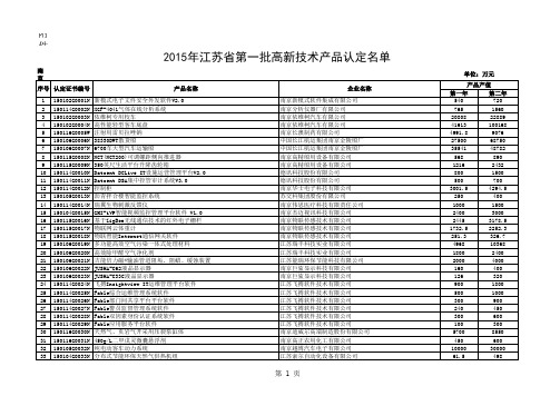
附件2:
南京市
单位:万元2015年江苏省第一批高新技术产品认定名单
无锡市
2015年江苏省第一批高新技术产品认定名单
单位:万元
徐州市
单位:万元2015年江苏省第一批高新技术产品认定名单
常州市
2015年江苏省第一批高新技术产品认定名单
单位:万元
苏州市
2015年江苏省第一批高新技术产品认定名单
单位:万元
南通市
2015年江苏省第一批高新技术产品认定名单
单位:万元
连云港市
2015年江苏省第一批高新技术产品认定名单
单位:万元
淮安市
2015年江苏省第一批高新技术产品认定名单
单位:万元
盐城市
2015年江苏省第一批高新技术产品认定名单
单位:万元
扬州市
2015年江苏省第一批高新技术产品认定名单
单位:万元
镇江市
2015年江苏省第一批高新技术产品认定名单
单位:万元
泰州市
2015年江苏省第一批高新技术产品认定名单
单位:万元
宿迁市
2015年江苏省第一批高新技术产品认定名单
单位:万元。
桑德森标准产品数据表(数据表16810-A)2020年1月版说明书

Technical DataTechnical DaTa 25-16810-A January 2020 SpecificationSupply Voltage 15 to 30 VdcCable size / Type 0.5mm 2 ~ 2.5mm 2 /FIRETUF, FP200 or MICC Mounting Hole Centres 50 ~ 80mm Allowable Alarm Current25mA Allowable Remote Indicator Current25mAWiring hintsEach terminal is suitable for clamping up to 2 wires. Clamping of 2 wires of very different diameters under one screw is not recommended.DO NOT USE A POWER TERMINAL DRIVER.Suitable for mounting to mounting boxes with 50-80mm fixing centres.EFXN533 DoP044818EN54-7 Point Type Smoke Detectors EFXN525DoP044618EN54-5 Point Type Heat Detectors EFXN524DoP044518EN54-5 Point Type Heat Detectors EFXN526DoP044718EN54-5 Point Type Heat Detectors EFXN632DoP044918EN54-5 Point Type Heat Detectors EN54-7 Point Type Smoke DetectorsFXN922DoP0405122831Detector InstalledDetector RemovedE n d o f L i n e M o n i t o rE n d o f L i n e R e s i s t o rGeneralIf difficulty is experienced when mounting the detector, this may be due to the following:Wiring causing an obstruction - move or shorten wires. Although the base is tolerant to uneven mounting surfaces, a very uneven surface may cause the base to deform when the mounting screws are tightened down - loosen screws to reduce this or slide base to a more flat position.WaRninG: DO NOT USE HIGH VOLTAGE TESTERS WHEN DETECTORS OR CONTROL PANEL ARE CONNECTED TO THE SYSTEM.Zener Diode Switch action eFDB800 (cDB300 & MDB800)eatonEMEA Headquarters Route de la Longeraie 71110 Morges, Switzerland Eaton.euTEL: +44 (0) 1302 321541FAX: +44 (0) 1302 303220******************************************************© 2020 EatonAll Rights ReservedEaton is a registered trademark.All trademarks are property of their respective Eaton Electrical Systems Ltd.Wheatley Hall Road Doncaster DN2 4NBTEL: +44 (0) 1302 303303 FAX: +44 (0) 1302 367155Utilising locking T a bThe Mounting base includes an optional feature to prevent the removal of the detector without the use of a tool.1. Remove the standard fit retaining clip.2. Insert the locking clip which is located at the centre of the base as shown.Mount the detector onto the base as described in Detector Installation (see over) and rotate fully clockwise until it finally clicks.The detector is now locked into position. Remove by utilising a suitable tool (eg a thin screwdriver) into the hole in the detector cover. Gently push the tool into the detector and rotate anti-clockwise.BaseOrder Codes Conventional Photoelectric Smoke Detector - Cooper EFXN520(CDBB300 / FXN520)EFDB800(CDB300 / MDB800) EFXN533 Conventional Heat Detector - Class A2R - Cooper EFXN525Conventional Heat Detector - Class BS - Cooper EFXN524Conventional Heat Detector - Class CS - CooperEFXN526Conventional Photo/Thermal - Class A2S (Heat Performance) - Cooper EFXN632Bi-Wire Programmable Conventional Photoelectric, Photo/Thermal (A2S), Heat Detector (A1R, BS or CS) - JSBEFXN520(CDBB300 / FXN520)FXN922Detector Features (Photoelectric & Photo/Thermal)All Photoelectric and Photo/Thermal detectors, automatically compensate for gradual increases in the scatter signal due to contamination e.g. dust build up.Self-check Features Of The Bi-wire DetectorThe Self-Check feature monitors for the failure of the internal primary alarm circuitry.Under this condition, the detector will still register an alarm condition via the yellow LED. Following such a failure, the yellow LED will remain on following a reset, signaling a fault at the main panel and the detector must be replaced.BiWire detectors, automatically compensate for gradual increases in the scatter signal due to contamination e.g. dust build up. If excessive dust occurs, the yellow LED will show continuously. If this occurs, the maintenance procedure should be conducted.The yellow LED will also light continuously if the detectors optical sensor signal begins to reduce below its normal level (chamber monitoring).In addition, the BiWire range has an isolator that opens if the internal power fails in the detector, giving rise to a zone fault at the main panel.When used with a BiWire compatible panel with Self Check features, the BiWireDetectors range of detectors can be instructed to blink their yellow LED every 2 seconds by a command from the main panel, to aid the search for a break in the zone cabling or an open detector isolator.Detector installationFit detector to mounting base and rotate clockwise until the detector drops into place. Continue to rotate clockwise until the detector clicks into place and no further rotation is possible. If the detectors are required to be locked into position, refer to the ‘UtilisingLocking Tab’ section.Smoke detectors are supplied fitted with dust covers for general protection against airborne contaminates.These must be removed from all detectors before the fire system is commissioned.NB. These dust covers do not provide adequate protection against quantities of dust generated by building workT estingAll detectors must be tested following installation or routine service andmaintenance. It is recommended that these tests are carried out by a competent person. Authorised personnel must be informed that the fire system will betemporarily out of service before commencing testing. To prevent unwanted alarms, ensure that the the panel is in test mode and it may be appropriate to disable some or all of the sounder circuits.. When all tests are complete, restore panel to normal operation and notify authorised personnel that the system is operational.Smoke Detectors:Subject the detector to be tested to a controlled amount of an approved synthetic smoke aerosol via a smoke detector test pole. Suitable products are available for example, from No Climb Products Ltd.Check that the red LED on the detector latches into alarm within 30 seconds. If an optional remote LED is fitted, check that this also lights.Ensure that the control panel activates into alarm.Reset the detector from the control panel unless automatically reset by the panel in test mode.This procedure will test the smoke sensing circuitry of the Photo/Thermal Detector.heat Detectors:Using a heat gun or hair dryer capable of generating temperatures of up to 95°C,direct the heat source towards the heat sensing elements, visible through the side of the outer cover, from a distance of 15 to 30cm. Care should be taken not to allow the plastic surface temperature to exceed 110°C otherwise damage may occur.When the temperature reaches the ‘Alarm Temperature’ (see Specifications above), check that the red LED on the detector latches into alarm. If an optional remote LED is fitted, check that this also lights.Ensure that the control panel activates into alarm.Reset the detector from the control panel unless automatically reset by the panel in test mode.This procedure will test the heat sensing circuitry of the Photo/Thermal Detector.MaintenanceOnly minimal maintenance can be performed on this range of detectors as they do not contain any site serviceable parts. The frequency of maintenance and will depend on the environment towhich the detector is exposed but should be at least annually. Dusty or damp environments will demand more frequent maintenance.Remove the detector from its mounting base.Use a vacuum cleaner to remove dust build up from around the smoke entryapertures of a smoke detector, or from around the heat sensing element of a heat detector.For smoke detectors, visually inspect the insect mesh for blockages. If these can not be cleared by vacuuming, the detector must be replaced.Re-fit detector to its mounting base and test as described above.Detectors that fail the testing procedure must be replaced.EFXN533EFXN525EFXN524EFXN526EFXN632FXN922Operating voltage 15 to 30 Vdc 15 to 30 Vdc 15 to 30 Vdc 15 to 30 Vdc 15 to 30 Vdc 15 to 30 Vdc Standby current (max) 30μA 30μA 30μA 30μA 30μA 80μA Start up current (max 20 sec)340μA N/A N/A N/A 340μA 340μA Alarm current (max)25mA 25mA 25mA 25mA 25mA 25mAAmbient temperature (max)60ºC45ºC60ºC75ºC45ºCOpto Mode 60ºCOpto-Heat Mode 45°CA1R Rate of Rise Mode 45°C BS Fixed Temp Mode 60°C CS Fixed Temp Mode 80°C Ambient temperature (min)-20ºC -20ºC -20ºC -20ºC -20ºC -10ºCAlarm temperature (static)N/A60ºC77ºC90ºC60ºCOpto-Heat Mode 60°CA1R Rate of Rise Mode 60°C BS Fixed Temp Mode 77°C CS Fixed Temp Mode 92°C Heat detector class –as defined by EN54-5:2000N/A A2R BS CS A2S See above Relative humidity (non-condensing)0 to 95%0 to 95%0 to 95%0 to 95%0 to 95%0 to 95%Height (without base)34mm 43mm 43mm 43mm 43mm 43mm Height (with base)47mm 56mm 56mm 56mm 56mm 56mm Diameter 100.5mm 100.5mm 100.5mm 100.5mm 100.5mm 100.5mm Weight 78g 76g 76g 76g 78g 78g Material PC/ABS PC/ABS PC/ABS PC/ABS PC/ABS PC/ABS ColourWhite White White White White White Bi-Wire compatible No No No No No Yes Self check featuresNoNoNoNoNoYes。
BNS 260 生活用电器安全设备手册说明书

DataOrdering dataProduct type descriptionBNS 260-11/01ZG-R Article number (order number)101184376EAN (European Article Number)4030661321745eCl@ss number, Version 9.027-27-24-02CertificationsCertificates DGUVTÜVcULus EACGeneral dataProduct nameBNS 260StandardsIEC 60947-5-3 BG-GS-ET-14 Installation conditions(mechanical)quasi-flush Enclosure materialGlass-fibre, reinforced thermoplastic Gross weight 60 g General data - FeaturesCoding Yes BNS260-11/01ZG-RLong lifeSmall bodyPre-wired cableno mechanical wear26 mm x 36 mm x 13 mmInsensitive to soilingThermoplastic enclosure Concealed mounting possible Insensitive to transverse misalignmentIntegral System Diagnostics,YesstatusNumber of openers2Number of shutters1Number of safety contacts2Number of cable wires6Safety appraisalStandards ISO 13849-1Mission Time20 Year(s)Safety appraisal - Safety outputsB10d- Value Normally-closed25,000,000 Operationscontact/Normally open contact(NC/NO)Mechanical dataActuating element MagnetDoor hinge RightEnsured switch distance "ON" S5 mmaoEnsured switch distance "OFF" S15 mmarAxial misalignment, a horizontal and vertical misalignment of the safetysensor and the actuator are tolerated. The possible misalignment dependson the distance of the active surfaces of the sensor and the actuator. Thesensor remains active within the tolerance range.Direction of motion Head-on to the active surfaceMechanical data - Connection techniqueTerminal Connector CableLength of cable 1 mWire cross-section0.25 mm2Material of the Cable mantle PVCMechanical data - DimensionsHeight of sensor36 mmLength of sensor13 mmWidth of sensor26 mmAmbient conditionsProtection class IP67Ambient temperature, minimum-25 °CAmbient temperature, maximum+70 °CStorage and transporttemperature, minimum-25 °CStorage and transporttemperature, maximum+70 °CResistance to vibrations to EN60068-2-610 … 55 Hz, amplitude 1 mmRestistance to shock30 g / 11 msElectrical dataVoltage type DC (direct current)Switching voltage, maximum24 VDCSwitching current, maximum0.01 ASwitching capacity, maximum0.24 WSwitching frequency, maximum 5 HzStatus indicationNote (Integral SystemDiagnostics, status )The LED is illuminated when the guard is closed. Scope of deliveryIncluded in delivery Actuators must be ordered separately. AccessoryRecommendation (actuator)BPS 260SRB-E-301STSRB-E-201LCNotesNote (General)Contact symbols shown for the closed condition of the guard device. The contact configuration for versions with or without LED is identical.Circuit exampleNote (Wiring diagram)Contact S21-S22; S13-S14 must be integrated in the safety circuit. Ordering codeProduct type description:BNS 260-(1)(2)Z(3)-(4)-(5)(1)11 1 NO contacts/1 NC contact02 2 NC contact(2)without with diagnostic output/01 1 NC contact(3)without without LED switching conditions displayG with LED switching conditions display(4)without Pre-wired cableST with connector(5)L Door hinge on left-hand sideR Door hinge on right-hand sidePicturesProduct picture (catalogue individual photo)ID: kbns2f23| 314,7 kB | .jpg | 352.778 x 246.239 mm - 1000 x 698Pixel - 72 dpi| 25,0 kB | .png | 74.083 x 51.858 mm - 210 x 147Pixel - 72 dpi| 39,7 kB | .jpg | 27.093 x 18.881 mm - 320 x 223 Pixel- 300 dpiDimensional drawing basic componentID: kbns2g05| 131,1 kB | .jpg | 352.425 x 417.336 mm - 999 x 1183Pixel - 72 dpi| 4,5 kB | .png | 73.731 x 87.489 mm - 209 x 248 Pixel- 72 dpi| 34,5 kB | .jpg | 112.536 x 133.35 mm - 319 x 378Pixel - 72 dpi| 37,3 kB | .cdr |DiagramID: kbns2k04| 25,1 kB | .jpg | 112.889 x 27.164 mm - 320 x 77 Pixel- 72 dpi| 19,5 kB | .cdr |Characteristic curveID: kbns2d03| 36,8 kB | .cdr || 40,4 kB | .jpg | 112.889 x 74.789 mm - 320 x 212Pixel - 72 dpi| 18,5 kB | .png | 74.083 x 49.036 mm - 210 x 139Pixel - 72 dpiCharacteristic curveID: kbns2d02| 19,2 kB | .png | 74.083 x 49.389 mm - 210 x 140Pixel - 72 dpi| 40,8 kB | .jpg | 112.889 x 75.142 mm - 320 x 213Pixel - 72 dpi| 36,3 kB | .cdr |Clipart| 20,1 kB | .cdr || 1,7 kB | .png | 74.083 x 52.564 mm - 210 x 149 Pixel- 72 dpiK.A. Schmersal GmbH & Co. KG, Möddinghofe 3, D-42279 WuppertalThe details and data referred to have been carefully checked. Images may diverge from original. Further technical data can be found in the manual. Technical amendments and errors possible.Generated on 08.07.2020 19:14:08。
FST600-205隔爆型温度变送器产品说明书
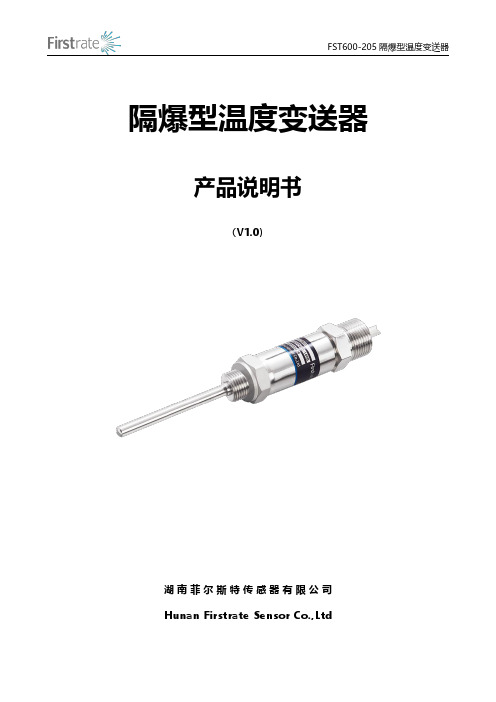
隔爆型温度变送器产品说明书(V1.0)湖南菲尔斯特传感器有限公司Hunan Firstrate Sensor Co.,Ltd●重要声明非常感谢您购买菲尔斯特传感器(变送器),我们为您真诚服务到永远。
菲尔斯特追求卓越不凡的品质,更注重良好的售后服务,如有问题,请拔打:400-607-8500(7×24h)。
操作错误会缩短产品的寿命,降低其性能,严重时可能引起意外事故。
请您在使用前务必仔细熟读本说明书。
将本说明书交到最终用户手中。
请妥善保管好说明书,以备需要时查阅。
说明书供参考所用,具体设计外形以实物为准。
●产品概述FST600-205防爆型工业通用温度变送器是由热电阻(偶)与温度变送器电路组成,采用二、三线制信号输出方式,带有非线性校正电路,可直接测量工业过程中的液体、气体介质和各种特质的温度将温度信号转换成与温度信号成性关系的电流4~20mA/电压0~5VDC、1~5VDC等信号输出,送显示仪表、调节记录仪表或计算机进行集散控制。
本产品广泛应用于石油、化工、冶金、电力、轻工、纺织、食品等行业,可与本公司生产的CH系列仪表及计算机等配套使用,组成各种温度测量控制系统。
FST600-205系列防爆型压力变送器的防爆性能符合《GB3836.1-2010爆炸性气体环境用电气设备第一部分:通用要求》及《GB3836.2-2010爆炸性气体环境用电气设备第二部分:防爆型“d”》的规定。
防爆型防爆标志为ExdIICT6Gb,适用与工厂内具有IIA、IIB、IIC级,T1-T6组成的可燃性气体或蒸汽以及空气形成的爆炸性混合物的环境中。
●原理概述FST600系列防爆型温度变送器是一种将温度变量转换成可传送的标准化输出的仪表,主要用于工业过程温度参数的测量和控制。
FST600系列防爆型温度变送器由两部分组成:传感器和信号转换器。
传感器主要由热点偶或热电阻;信号转换器主要由测量单元、信号处理和转换单元组成。
重庆市计量质量检测研究院_企业报告(业主版)

1.4.1 重点项目
(1)质检技术服务(174)
重点项目
项目名称
中标单位
中标金额(万元) 公告时间
TOP1
绿色产品安全检测平台(三重四 级杆液质联用仪)
福建省科学器材进 出口有限公司
668.1
2023-06-29
本报告于 2023 年 08 月 31 日 生成
3/35
重点项目
项目名称
中标单位
中标金额(万元) 公告时间
强检计量能力提升装备采购项目 (第二批、第四批)-第四次
绿色产品安全检测平台 (CQS23A00187)分包四中标结果 变更公告
四川省外贸集团成 都进出口有限责任 公司
绿色产品安全检测平台
重庆润银科贸发展 有限公司
105.0 97.6
2023-08-04 2023-05-04
TOP7
重庆市计量质量检测研究院第二 分院检测大楼维修改造中标公告
国中建设(重庆)有 限公司
TOP7
燃 气 安 全 检 测 及 实 验 室 建 设 重庆松昌科技有限 (CQS23A00753)中标(成交)结 公司
79.5
果公告
TOP8
可燃气体探测器闭环高低温、湿 热试验箱及配套设备
深圳泽保智能科技 有限公司
68.9
TOP9
深圳泽保智能科技 激光跟踪仪、荧光光谱仪等设备 有限公司
68.9
2023-08-03 2023-08-30 2023-08-11
重庆秦度科技有限 激光跟踪仪、荧光光谱仪等设备 公司
绿色产品安全检测平台
四川省外贸集团成 都进出口有限责任 公司
TOP4 TOP5
绿 色 产 品 安 全 检 测 平 台 重庆洽捷科技有限 (CQS23A00187)中标(成交)结 公司 果公告
贝利摩B6600S-400冷暖水阀数据表说明书

B6600S-400•ApplicationStainless Steel Ball and StemType overviewTypeDN B6600S-400150Technical dataFunctional dataValve size 6" [150]Fluidchilled or hot water, up to 60% glycol Fluid Temp Range (water)0...250°F [-18...120°C]Body Pressure Rating ANSI Class 125, standard class B Close-off pressure ∆ps 175 psiFlow characteristic equal percentage Servicing maintenance-free Flow Pattern 2-way Leakage rate0% for A – AB Controllable flow range 75°Cv400Cv Flow RatingA-port: as stated in chart B-port: 70% of A – AB CvMaterialsValve body Cast iron - GG 25Stem stainless steel Stem seal EPDM (lubricated)SeatPTFEPipe connection pattern to mate with ANSI 125 flange O-ring EPDM (lubricated)Ballstainless steel Suitable actuators Non-Spring GRB(X)Electrical fail-safeGKRB(X)Safety notesWARNING: This product can expose you to lead which is known to the State of California to cause cancer and reproductive harm. For more information go to Product featuresThis valve is typically used in air handling units on heating or cooling coils, and fan coil unit heating or cooling coils. Some other common applications include Unit Ventilators, VAV box re-heat coils and bypass loops. This valve is suitable for use in a hydronic system with variable flow.B6600S-400 Flow/Mounting detailsDimensionsType DNB6600S-400150GRB, GRXA B C D E F G I Number of BoltHoles15.3" [388]12.4" [315]15.4" [391]9.5" [241]5.5" [140]5.5" [140]9.5" [241]0.9" [22]8GKRB, GKRXA B C D E F G I Number of BoltHoles15.3" [388]12.4" [315]15.8" [401]9.8" [248]5.5" [140]5.5" [140]9.5" [241]0.9" [22]8GRX, GKRXB6600S-400A B C D E F G I Number of BoltHoles19.0" [483]12.4" [315]18.5" [470]9.5" [241]5.5" [140]5.5" [140]9.5" [241]0.9" [22]8GRX, GKRXA B C D E F G I Number of BoltHoles19.0" [483]12.4" [315]18.5" [470]9.5" [241]5.5" [140]5.5" [140]9.5" [241]0.9" [22]8Modulating, Electrical Fail-Safe, 24 V, for DC2...10 V or 4...20 mA Control SignalTechnical dataElectrical data Nominal voltage AC/DC 24 VNominal voltage frequency50/60 HzPower consumption in operation12 WPower consumption in rest position 3 WTransformer sizing21 VA (class 2 power source) / heater 21 VAElectrical Connection18 GA plenum cable, 3 ft [1 m], with 1/2"conduit connectorOverload Protection electronic thoughout 0...90° rotationFunctional data Operating range Y 2...10 VOperating range Y note 4...20 mA w/ ZG-R01 (500 Ω, 1/4 W resistor)Input Impedance100 kΩ for 2...10 V (0.1 mA), 500 Ω for 4 (20)mA, 1500 Ω for PWM, On/Off and Floating pointOperating range Y variable Start point 0.5...30 VEnd point 2.5...32 VOptions positioning signal variable (VDC, on/off, floating point)Position feedback U 2...10 VPosition feedback U note Max. 0.5 mAPosition feedback U variable VDC variableBridging time (PF)2 sBridging time (PF) variable0...10 sPre-charging time 5...20 sDirection of motion motor selectable with switch 0/1Direction of motion fail-safe reversible with switchManual override under coverAngle of rotation Max. 95°Angle of rotation note adjustable with mechanical stopRunning Time (Motor)150 s / 90°Running time motor variable90...150 sRunning time fail-safe<35 sNoise level, motor52 dB(A)Noise level, fail-safe61 dB(A)Position indication Mechanically, 30...65 mm strokeSafety data Degree of protection IEC/EN IP66/67Degree of protection NEMA/UL NEMA 4XEnclosure UL Enclosure Type 4XAgency Listing cULus acc. to UL60730-1A/-2-14, CAN/CSAE60730-1:02, CE acc. to 2014/30/EU and2014/35/EUQuality Standard ISO 9001FootnotesBridging timeSafety dataAmbient temperature -22...122°F [-30...50°C]Ambient temperature note -40...50°C for actuator with integrated heating Storage temperature -40...176°F [-40...80°C]Ambient humidity Max. 100% RH Servicingmaintenance-freeMaterialsHousing material Die cast aluminium and plastic casing†Rated Impulse Voltage 800V, Type of action 1.AA, Control Pollution Degree 3Product featuresElectrical interruptions can be bridged up to a maximum of 10 s.In the event of a power failure, the actuator will remain stationary in accordance with the set bridging time. If the power failure is greater than the set bridging time, then the actuator will move into the selected fail-safe position.The bridging time set ex-works is 2 s. This can be modified on site in operation with the use of the Belimo service tool MFT-P.Settings: The rotary knob must not be set to the "PROG FAIL-SAFE" position!For retroactive adjustments of the bridging time with the Belimo service tool MFT-P or with the ZTH EU adjustment and diagnostic device only the values need to be entered.AccessoriesGatewaysDescriptionType Gateway MP to BACnet MS/TP UK24BAC Gateway MP to Modbus RTU UK24MOD Gateway MP to LonWorksUK24LON Electrical accessoriesDescriptionType Feedback potentiometer 140 Ω add-on, grey P140A GR Feedback potentiometer 500 Ω add-on, grey P500A GR Feedback potentiometer 1 kΩ add-on, grey P1000A GR Feedback potentiometer 2.8 kΩ add-on, grey P2800A GR Feedback potentiometer 5 kΩ add-on, grey P5000A GR Feedback potentiometer 10 kΩ add-on, grey P10000A GR Auxiliary switch 1 x SPDT add-on S1A Auxiliary switch 2 x SPDT add-onS2A Service Tool, with ZIP-USB function, for programmable andcommunicative Belimo actuators, VAV controller and HVAC performance devicesZTH USService toolsDescriptionTypeConnection cable 10 ft [3 m], A: RJ11 6/4 ZTH EU, B: 3-pin Weidmüller and supply connectionZK4-GEN Service Tool, with ZIP-USB function, for programmable and communicative Belimo actuators, VAV controller and HVAC performance devicesZTH USElectrical installationINSTALLATION NOTESActuators with appliance cables are numbered.Provide overload protection and disconnect as required.Actuators may also be powered by DC 24 V.Only connect common to negative (-) leg of control circuits.A 500 Ω resistor (ZG-R01) converts the 4...20 mA control signal to 2...10 V.Control signal may be pulsed from either the Hot (Source) or Common (Sink) 24 V line.For triac sink the Common connection from the actuator must be connected to the Hotconnection of the controller. Position feedback cannot be used with a triac sink controller; theactuator internal common reference is not compatible.IN4004 or IN4007 diode. (IN4007 supplied, Belimo part number 40155).Actuators are provided with a numbered screw terminal strip instead of a cable.Actuators may be controlled in parallel. Current draw and input impedance must be observed.Master-Slave wiring required for piggy-back applications. Feedback from Master to controlinput(s) of Slave(s).Meets cULus requirements without the need of an electrical ground connection.Warning! Live electrical components!During installation, testing, servicing and troubleshooting of this product, it may be necessaryto work with live electrical components. Have a qualified licensed electrician or other individualwho has been properly trained in handling live electrical components perform these tasks.Failure to follow all electrical safety precautions when exposed to live electrical componentscould result in death or serious injury.Wiring diagramsOn/Off Floating PointVDC/mA Control PWM ControlOverride Control Master - SlaveNEMA 4 HeaterDimensions。
细述电容式压力变送器与扩散硅压力变送器区别

电容式压力变送器与扩散硅压力变送器区别压力变送器可分为:电容式压力变送器与扩散硅压力变送器。
电容式压力变送器:电容式压力变送器自20世纪80年代诞生至今己有20多年历史,由于它精度高,耐腐蚀,耐污染,稳定性好,是冈内外公认的检渊低真空压力的理想仪表。
美国的M.K.S公司是全球生产电容式压力变送器的主要生产厂家,涉及民用工业的各个领域,并在航天工业、核工业等军事工业中发挥着独特的作用。
这种压力变送器是利用弹性薄膜在压差作用下产生压变引起电容变换的原理制成的,它由检测部分和转换电路组成,.检测部分有真空腔和检测腔两个腔体。
真空腔为全密封结构,经质谱检漏仪检漏合格后,通过长时间排气,最后将排气管密封而形成,井备有消气剂以消除残余气体,长期保持高真空.固定极板位于真空腔中,由极板引出线引至腔外.检测膜片置于高真空的真空腔及连接低真空待测系统的检测腔之间,检测膜片为可动极板,其与固定极板形成一个平板电容器,有一定的电容(J.。
被测的低真空压力通过检测孔进人检测腔,检测膜片产生挠曲,改变了其与固定极板的距离,电容值也随之改变。
不同的低真空压力值决定不同的电容值。
最后电容信号被输送到电路转换部分,电路转换部分将电容信号通过变换、整理、放大等环节,输出一个标准电压或电流信号,它与真空压力成正比。
该类型压力变送器为高灵敏度差压测量,零点稳定。
动态响应特性好,适应性强,一般适用于静压力的测最.扩散硅压力变送器:20世纪90年代中期,美国Icscnsor,公司,Nova公司应用硅品石和硅品片益合两项尖端科技生产了新型扩散硅压力传感器并开发出具有精度高、重复性小、抗腐蚀的扩散硅压力变送器过程压力通过隔离膜片、密封硅油传输到扩散硅膜片上,同时参考端的压力(大气压)作用于膜片的另一端。
这样膜片两边的压差产生一个压力场,使膜片的一部分压缩。
另一部分拉伸,在压缩区和拉伸区分别有两个应变电阻片,以感受压力引起的阻值的变化,从而将压力信号转换为电信号.扩散硅在低温零度以下、高温85℃以上难以正常使用,也不适用于20MPa 以上的高压。
西森法兰式压力变送器参数

输出信号 2 线制,4~20mADC HART 输出,数字通讯,HART 协议加 载在 4~20mADC 信号上。 输出信号极限:Imin=3.9mA,Imax=20.5mA
1
报警电流(模式可设置) 低报模式(最小):3.6 mA 高报模式(最大):21 mA 不报模式(保持):保持故障前的有效电流值 报警电流标准设置:高报模式
5、响应时间
放大器部件阻尼常数为 0.1s;传感器和液位法兰 时间常数为 0.2~2s,取决于量程及量程比。附加 的可调时间常数为:0.1~60s。
6、一般条件
6.1 安装条件 通过液位法兰变送器可直接固定于任何位置。最佳 状态是使过程法兰轴处于垂直状态,位置偏差将产 生可校正的零位偏移。电子表壳最大可旋转 360°,定位螺钉可将其固定于任何位置。 6.2 环境条件 环境温度 最 低:取决于填充液 最 高:85℃ 带液晶显示、氟橡胶密封圈时 -20~65℃ 储存温度/运输温度 最 低:取决于填充液 最 高:85℃ 相对湿度:0~100% 抗冲击 加速度:50g 持续时间:11ms 抗震动:2g 至 500Hz 电磁兼容性(EMC) 见下页表 3《电磁兼容性附表》 6.3 过程介质极限 介质温度极限:-30~180℃ 变送器本体压力极限 从 3.5kPa 绝对压力至额定压力,保护压力可大于
不锈钢表壳可选
外壳密封圈:丁腈橡胶(NBR)
铭
牌:不锈钢 304
电气连接
M20X1.5 电缆密封扣,接线端子适用于 0.5~2.5mm2 的导
线。
2
·过程连接 变送器低压侧有 UNF 7/16``内螺纹。变送器高压 侧的液位法兰符合 ANSI 标准或 DIN 标准。可直接安装,参考尺寸图。 外壳防护等级:IP67
ABB 电磁流量计中文说明书

天康集团(压力变送器)选型样本
存贮器中。变送器掉电后,数据仍保存,故而上电后变送 器能立即工作。
数/模转换与信号传送 过程变量以数字式数据存贮,可以进行精确地修正和 工程单位的转换。信号经修正后的数据转换为模拟输出信 号。HART手操器可以直接以数据信号方式存取传感器读 数,不经过数/模转换以得到更高精度。
三、产品说明
传感膜头 3051C型采用先进技术及生产线制造的高品质传感 器。传感器与过程介质和外部环境保持机械、电气及热隔 离。传感器远离过程法兰,移至电子外壳的颈部,可实现 机械隔离和热隔离。该设计使传感器不与过程热源直接接 触,并释放了传感器杯体上的机械应力,可提高静压性 能。 玻璃密封的压力输送管与传感器杯体绝缘安装,保证 了电气绝缘,可提高电子线路的灵活性、性能与耐瞬变电 压保护的能力。 3051C型传感膜头还进行温度测量,用于补偿温度影 响。 在工厂的特性化过程中,所有传感器都经受了整个工 作范围内的压力与温度循环测试。根据由此得来的数据产 生修正系数,然后将系数贮存于传感膜头的内存中,从而 可保证变送器运行过程中能精确地进行信号修正。 该种传感膜头的内存也可帮助加快维修过程。因为所 有膜头的特性值都贮存在膜头中,所以可直接更换线路板 而无需重新校验或拆下独立的贮存。使用HART手操器可 以方便地对3051型进行组态。组态由两部分组成。首先, 设定变送器的工作参数,包括:存修正系数的PROM。 传感膜头内还有线路板,它将输入的电容与温度信号 直接转换成可供电子板模块进一步处理的数字化信号。
1
ANHUI TIANKANG(GROUP)SHARES CO.,LTD.
3051L型液位变送器 液位测量精度达0.1% 校验量程从0.4kPa至2.1MPa 平膜片式,2-,4-,与6英寸伸出式膜片 多种灌充液可选,可满足不同应用场合要求 小巧而质轻,易于安装与维护 接液件材料:不锈钢,哈氏合金和钽
变压器温控器接点误差校验的相关问题探讨

变压器温控器接点误差校验的相关问题探讨郝 锴,蒋兆荣(成都电业局,四川成都 610041)摘 要:在进行变压器温控器检定时,不仅要保证温度指示值的准确性,还必须认真考察温控器内部的接点动作及返回的准确性和可靠性。
通过分析国标检定规程、行业制造规程以及实际试验数据,提出了符合电力变压器运行要求的温控器接点检定方法,并且针对现场检定提出了满足规程要求的接点快速检测方法。
关键词:变压器温控器;接点;规程;快速检测方法Ab stra ct:When ca libra ting thermome t e rs for transfor m ers,we sh oul d guaran t ee not only the p rec isi on of the indicati on,bu t al2 s o the the p rec ision and re liability of t he contac t.By analysing the nati onal standard cali brati on regula ti on,the industry m anu2 fac turi ng st anda rd and the prac tice t e sts da t a,we propose the contacts cali brati ng me th ods s pecific t o ther mo m ete rs for trans2 for me rs.A fast te st me th od for l oca l e contacts cali brati on is als o put for ward.Key wor d:the r mo m eters for transf o r me rs;contacts;reg u l a tions;fast te st me th od中图分类号:T M406 文献标识码:B 文章编号:1003-6954(2008)06-0061-02 变压器温控器不仅用于测量变压器的温度,还关系变压器冷却器自启动、强油循环变压器冷却器全停保护、温高报警、温高跳闸等功能,其重要性不言而喻。
贝思力 2020系列变压器温控器 说明书

安全指导在安装、操作和运行此温控器前,请仔细阅读本说明书,并妥善保管。
警告注意此温控器有危险电压,并监控危险的电力变压器。
如果不按本手册的规定操作可能会导致财产损失或人员严重受伤甚至死亡。
只有合格的技术人员才允许操作此温控器,在进行操作前,要熟悉使用手册中所有安全说明、安装、操作和维护规程。
本温控器的正常运行取决于正确的运输、安装、操作和维护。
1.此温控器的工作电源为: 220VAC ~240VAC ,50Hz/60Hz ; 2.请确保所有电气连接正确、牢固;3.此温控器接通电源后,请不要接触外露的带电部件; 4.端子L 、N 、1、2、3、4、5、6、7带有危险电压; 5.风机输出端子1、2、3、4、5、6与7间请勿短路;6.对变压器进行高压测试时,请先将温控器与传感器分离,以免损坏温控器!1.使用前请仔细阅读说明书;2.此温控器只能按本公司规定的说明使用,未经授权的修改和使用非本公司所出 售或推荐的零配件都可能导致本系统出故障,甚至失效;3.避免在含有二氧化硫(SO 2)、硫化氢(H 2S )或其他腐蚀性气体的大气中使用 本温控器,否则会使继电器触点失效;4.整机安装好后,连接好有关引线,在确定无误的情况下方可送电运行;5.传感器探头请勿用打火机烧烤(火焰温度在800℃左右); 6.不要在继电器输出触点上施加比最大额定值大的电压、电流;7. 当实际产品为特殊/定做产品时,若说明书内容与“9 特殊机型附页”内容相冲突时,以“9 特殊机型附页”内容为准。
8.请将使用说明书放在容易拿到的地方,并送给所有使用者。
目录1.产品概述 (1)2.产品型号 (1)3.技术参数 (1)4.产品功能介绍 (2)5.产品操作说明 (3)6.产品电气接线(以BWDK-3208BE为例) (6)7.通讯规约 (7)8.产品安装 (9)9.常见问题 (10)10.特殊机型附页 (10)1.产品概述此温控器是为风冷干式变压器设计的新一代温度控制器,它采用先进的计算机控制技术和数据存贮技术设计而成,且在设计中采用了硬件和软件相结合的抗干扰措施,使产品具有了极强的抗干扰能力。
煤矿温度传感器
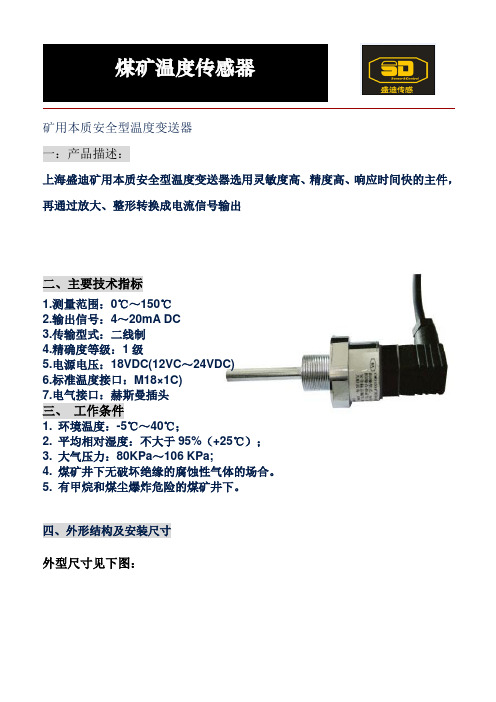
煤矿温度传感器
矿用本质安全型温度变送器
一:产品描述:
上海盛迪矿用本质安全型温度变送器选用灵敏度高、精度高、响应时间快的主件,再通过放大、整形转换成电流信号输出
二、主要技术指标
1.测量范围:0℃~150℃
2.输出信号:4~20mA DC
3.传输型式:二线制
4.精确度等级:1级
5.电源电压:18VDC(12VC~24VDC)
6.标准温度接口:M18×1C)
7.电气接口:赫斯曼插头
三、工作条件
1. 环境温度:-5℃~40℃;
2. 平均相对湿度:不大于95%(+25℃);
3. 大气压力:80KPa~106 KPa;
4. 煤矿井下无破坏绝缘的腐蚀性气体的场合。
5. 有甲烷和煤尘爆炸危险的煤矿井下。
四、外形结构及安装尺寸
外型尺寸见下图:
温度变送器的导线连接方式见下图:
接线:红色:(+)黑色:(-)或红色:(+)黄色:(-)
连接电缆穿过压线螺母与赫斯曼插头(GWD150型)连接,接线端子1接本安电源正端;接线端子2为4~20mA电流输出正端。
拧紧压线螺母以固定电缆线。
安全区与危险区之间通过本安电源连接,请参考本安电源使用说明书。
上海盛迪传感技术有限公司
上海松江区方塔北路605号(企德天地)10楼1001室
Tel:+86-21-57767320,57767321 Fax:+86-21-37605635
E-mail: info@
(中文)
SD传感与控制page 2 of 2。
ThermCal400干燥热温度计ibration器用户手册说明书

ThermCal400Dry Block Temperature CalibratorINSTRUCTION MANUALPlease read all the information in this booklet before using the unit. August 2013The ThermCal400IntroductionThe ThermCal400 calibrator provides a safe, dry, constant temperature source for checking and calibrating a wide range of temperature sensors, systems, indicators and thermometers It is fast and economical and can be used either on a bench top or as a portable field unit. The weight of the unit is only 11 pounds/five kilograms. The unit covers the temperature range from 5°C above ambient up to 400°C using a machined aluminum block as the heat transfer medium. The temperature control circuit is built into the unit.Features include:• Maximum temperature of 400°C/752°F• An independent over-temperature cutout• Up to eight setpoints can be stored & recalledEven though the unit heats up rapidly, highly efficient insulation and an internal cooling fan ensures that the case remains cool enough to handle even at maximum operating temperatures. The ThermCal400 calibrator has been designed to comply with all relevant electromagnetic interference and electrical safety regulations.-1-SpecificationFigures quoted are at the base of the well at the time of calibration.Temperature range: 5°C/9°F above ambient to 400°C/752°FOver-temperature limit: 450°C/842°FDisplay resolution: 0.1°Accuracy: ±0.25°C (30 to 200°C)±0.4°C (200 to 400°C)Stability (after 20 minutes): ±0.020°C (50 to 200°C)±0.040°C (200 to 400°C)Well to well radial uniformity: 0.015°C at 200°C & 0.025°C at 400°CHeat up time 20° C to 300°C: 9 minutesCool down 300°C to 100°C: 18 minutesImmersion Depth: 4.5" (114.3mm)Fan Cooling: AutomaticWeight: 11 lbs (5 Kg)Dimensions* (H x W x D): 8.75 x 8 x 8 inches/222.25 x 203.2 x 203.2 mm*excluding the carrying strapElectrical supplyVoltage Cycles Power230V 50/60Hz 900W120V 50/60Hz 900WNote: The above specifications are quoted for an ambient temperature range of 10°C/50°F to 30°C/86°F.Outside this range, the quoted figures may deteriorate but the unit will still work safely.-2-Working environmentThe calibrator units are designed to work safely under the following conditions:Ambient temperature range: 5°C/9°F to 40°C/104°FHumidity: Up to 95% relative humidity, non-condensingWarningWarning: HIGH TEMPERATURES ARE DANGEROUSAviso: LAS TEMPERATURAS ELEVADAS SON PELIHIGH TEMPERATURES ARE DANGEROUS: They can cause serious burns to operators and ignite combustible material. Accurate Thermal Systems has taken great care in the design of these units to protect operators from hazards, but operators should pay attention to the following points:• USE CARE AND WEAR PROTECTIVE GLOVES TO PROTECT HANDS• DO NOT put hot objects on or near combustible objects• DO NOT operate the unit close to inflammable liquids or gases• DO NOT place any liquid directly in your unit• At all times USE COMMON SENSEOperator SafetyAll operators of Accurate Thermal Systems equipment must have available the relevant literature needed to ensure their safety. It is important that only suitably trained personnel operate this equipment in accordance with the instructions contained in this manual and with general safety standards and procedures. If the equipment is used in a manner not specified by Accurate Thermal Systems, the protection provided by the equipment to the operator may be impaired. All Accurate Thermal Systems units have been designed to conform to international safety requirements and are fitted with a self-resetting over-temperature cutout. If a safety problem is encountered, switch off at the power socket and remove the plug from the supply.-3-Installation1. All Accurate Thermal Systems units are supplied with a power cable.2. Before connecting the power supply, check the voltage against the rating plate. Connect the powercable to a suitable plug according to the table below. Note that the unit must be earth groundedto ensure proper electrical safety.Electrical connections:220V-240V 110V-120VLive Brown BlackNeutral Blue WhiteEarth ground Green/yellow GreenThe fused plug supplied with the power lead for use in the UK is fitted with the following value fuse to protect the cable: 230V UK 4 AMPThe fuse in the unit protects the unit and the operatorNote that units marked 230V on the rating plate work at 220V; units marked 120V work at 110V. Inboth cases, however, the heating rate will degrade by approximately 8%. The rating plate is on therear of the unit.3. Plug the power cable into the socket on the rear of the unit.4. Place the unit on a suitable bench or flat workspace, or in a fume cupboard if required, ensuring thatthe air inlet vents on the underside are free from obstruction.After use, when you have finished heating samples, remember that parts of the unit may be very hot.Take the precautions listed earlier.-4-OPERATIONPreparation1.The heater design, temperature sensor and control circuit give good temperature control anduniformity, but make sure that there is a close fit of the probes in the block to allow efficient heattransfer. Contact us about an insert that more closely fits your probe or device being calibrated.2. Plug the power cable into the socket in the back of the unit. Connect the power cable to theelectrical supply and switch the power on.Setting the operating temperature1.To set the operating temperature required, press and hold either the up or down arrow button toincrement to the value required. Alternatively you can press the («PF) key to move over toindividual digits to set higher values much quicker. After 2 seconds your value will be set & retained.2.When you have the correct set temperature displayed the unit will start to heat or cool to thatvalue.3. Once the process value/actual temperature reaches the set point, allow the block to fully stabilize forat least 15 minutes before performing a calibration.Entering up to 8 setpoints for fast recall1. To input up to 8 setpoints press the first button on the left and then the 2nd button from the leftuntil the top line displays SP-0. Here you can enter up to 8 values for fast future recall. Do notchange any of the settings or values after SP-7. When finished entering values press the button onthe left one time.You’ll need to note which value is in which location for future recall.2. To select one of the 8 setpoints for use from the main display press the 2nd button from the left sothe top line displays M-SP. Next use the up arrow key to select one of the 8 setpoint values. Pressthe 1st key on the left twice for the value to be accepted.-5-Factory default control parametersThe parameters used in the controller have been developed by Accurate Thermal Systems to give the best unit performance for most applications. If the need arises the “AT” autotune command can be run to further optimize results based on the thermal block load and ambient conditions. Contact us for further support and details.Switching the display from Degrees C to Degrees F and vice versaTo switch the display press and hold down the left key until the display indicates “CN-t”, next press the 2nd key from the left one time and the top line will show “d-U” which is display units. Switch to either C or F. Based on which setting you use the parameters below must be changed to those shown. They will display by pressing the 2nd key from the left after setting C or F. After all values have been changed hold down the left most key so the controller resets and accepts the new values.Parameter Degrees C Degrees FSL-H 410.0 770.0SL-L 0.0 0.0To correct the calibration offset – press button on left, then button 2ndfrom the left until the parameter CN5 is displayedCN5 If in C multiply valueby 1.8 to switch to F If in F divide value by 1.8 to switch to C-6-Operator maintenanceNOTE THAT THIS EQUIPMENT SHOULD ONLY BE DISMANTLED BY PROPERLY TRAINED PERSONNEL. REMOVING THE FRONT OR REAR PANELS EXPOSES POTENTIALLY LETHAL VOLTAGES. THERE ARE NO OPERATOR MAINTAINABLE PARTS WITHIN THE EQUIPMENT.In the unlikely event that you experience any problems with your unit which cannot easily be remedied, you should contact your supplier and return the unit if necessary. Please include any details of the fault observed and remember to return the unit in its original packing. Accurate Thermal Systems will accept no responsibility for any damage to units that are improperly packed for shipment. If in doubt, contact your supplier.1.Cleaning: Before cleaning your unit, ALWAYS disconnect it from the power supply and allow it tocool below 50° C. Your unit can be cleaned by wiping with a damp soapy cloth. Care should beexercised to prevent water from running inside the unit. Do not use abrasive cleaners.2.Fuses: Your unit is protected by fuse. They should only be changed by suitably qualifiedpersonnel. If the fuse blow persistently, a serious fault is indicated and you may need to return theunit to your supplier for repair.ADDITIONAL INFORMATIONThe controller is factory preset with all parameters and calibration data and therefore cannot becalibrated or serviced in the field. Please contact Accurate Thermal Systems for arrangements to haveyour unit calibrated or serviced.-7-Replacement PartsThe following parts may be obtained from Anville Instruments Ltd. if replacements or alternatives are required: Part Number Description4163 UK 240 volt power cable with 13amp UK plug (5 amp fuse)4164 Euro style 240 volt power cable with R/A Schuko plug4150 US style 120 volt power cable4159 Instruction manual4150 Unit carrying strap4153 Insert extractorATS3041 insert 1/8, 3/16, ¼, 5/16 & 3/8” ATS3047 Blank insertATS3043 Insert 5 x 1/4" ATS3048 insert 1 x 9/16" & 1 x 1/4"ATS3044 Insert 2 x 1/4" & 2 x 3/8" ATS3049 insert 1 x 5/8" & 1 x 1/4"ATS3045 Insert 2 x 1/4" & 2 x 1/2" ATS3050 insert 1 x 11/16" & 1 x 1/4" ATS3046 Insert 1 x 1/4" ATS3051 insert 1 x 3/4" & 1 x 1/4"ATS3052 Carrying caseSpare PartsPart Number Description4146 225 watt, 120 volt heater4160 Temperature controller4147 PRT4145 Solid state relay4165 4 amp fuse (240 volt units)4157 8 amp fuse (120 volt units)-8-Contact InformationAccurate Thermal Systems LLC61 Mohr RoadBurlington, NJ 08016Ph: 609-326-3190Email:***********************Website: GUARANTEEThe unit is guaranteed against any defects in material or workmanship for the period of 3 years. This period is from the date of purchase, and within this period, all defective parts will be replaced free of charge provided that the defect is not the result of misuse, accident or negligence. Servicing under this guarantee should be obtained from the supplier. Not withstanding the description and specification(s) of the units contained in the Operator’s Manual, Accurate Thermal Systems hereby reserves the right to make such changes as it sees fit to the units or to any component of the units. This manual has been prepared solely for the convenience of Accurate Thermal Systems customers and nothing in this Instruction Book shall be taken as a warranty, condition or representation concerning the description, merchantability, fitness for purpose or otherwise of the units or components.-9-。
