T3.15AL250V(大威)
Victron Energy智能充电控制器MPPT250系列说明说明书
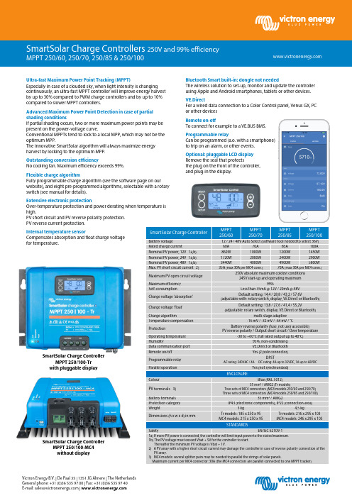
Victron Energy B.V. | De Paal 35 | 1351 JG Almere | The Netherlands General phone: +31 (0)36 535 97 00 | Fax: +31 (0)36 535 97 40 E-mail:***********************|SmartSolar Charge ControllerMPPT 250/60 MPPT 250/70 MPPT 250/85 MPPT 250/100Battery voltage12 / 24 / 48V Auto Select (software tool needed to select 36V)Rated charge current60A 70A 85A 100A Nominal PV power, 12V 1a,b) 860W 1000W 1200W 1450W Nominal PV power, 24V 1a,b) 1720W 2000W 2400W 2900W Nominal PV power, 48V 1a,b) 3440W 4000W 4900W 5800W Max. PV short circuit current 2) 35A (max 30A per MC4 conn.) 70A (max 30A per MC4 conn.)Maximum PV open circuit voltage 250V absolute maximum coldest conditions 245V start-up and operating maximumMaximum efficiency 99%Self-consumptionLess than 35mA @ 12V / 20mA @ 48V Charge voltage 'absorption' Default setting: 14,4 / 28,8 / 43,2 / 57,6V(adjustable with: rotary switch, display, VE.Direct or Bluetooth) Charge voltage 'float' Default setting: 13,8 / 27,6 / 41,4 / 55,2V(adjustable: rotary switch, display, VE.Direct or Bluetooth)Charge algorithmmulti-stage adaptive Temperature compensation -16 mV / -32 mV / -64 mV / °CProtectionBattery reverse polarity (fuse, not user accessible)PV reverse polarity / Output short circuit / Over temperatureOperating temperature -30 to +60°C (full rated output up to 40°C)Humidity95%, non-condensing Data communication port VE.Direct or Bluetooth Remote on/off Yes (2 pole connector)Programmable relay DPSTAC rating: 240VAC / 4A DC rating: 4A up to 35VDC, 1A up to 60VDCParallel operationYes (not synchronized)ENCLOSUREColourBlue (RAL 5012)PV terminals 3)35 mm² / AWG2 (Tr models)Two sets of MC4 connectors (MC4 models 250/60 and 250/70) Three sets of MC4 connectors (MC4 models 250/85 and 250/100)Battery terminals 35 mm² / AWG2Protection category IP43 (electronic components), IP22 (connection area)Weight3 kg 4,5 kgDimensions (h x w x d) in mmTr models: 185 x 250 x 95 MC4 models: 215 x 250 x 95 Tr models: 216 x 295 x 103 MC4 models: 246 x 295 x 103STANDARDSSafetyEN/IEC 62109-11a) If more PV power is connected, the controller will limit input power to the stated maximum.1b) The PV voltage must exceed Vbat + 5V for the controller to start. Thereafter the minimum PV voltage is Vbat + 1V.2) A PV array with a higher short circuit current may damage the controller in case of reverse polarity connection of the PV array.3) MC4 models: several splitter pairs may be needed to parallel the strings of solar panels.Maximum current per MC4 connector: 30A (the MC4 connectors are parallel connected to one MPPT tracker)Bluetooth Smart built-in: dongle not neededThe wireless solution to set-up, monitor and update the controller using Apple and Android smartphones, tablets or other devices.VE.DirectFor a wired data connection to a Color Control panel, Venus GX, PC or other devicesRemote on-offTo connect for example to a VE.BUS BMS.Programmable relayCan be programmed (a.o. with a smartphone) to trip on an alarm, or other events.Optional: pluggable LCD display Remove the seal that protectsthe plug on the front of the controller, and plug-in the display.Ultra-fast Maximum Power Point Tracking (MPPT)Especially in case of a clouded sky, when light intensity is changing continuously, an ultra-fast MPPT controller will improve energy harvest by up to 30% compared to PWM charge controllers and by up to 10% compared to slower MPPT controllers.Advanced Maximum Power Point Detection in case of partial shading conditionsIf partial shading occurs, two or more maximum power points may be present on the power-voltage curve.Conventional MPPTs tend to lock to a local MPP, which may not be the optimum MPP.The innovative SmartSolar algorithm will always maximize energy harvest by locking to the optimum MPP.Outstanding conversion efficiencyNo cooling fan. Maximum efficiency exceeds 99%.Flexible charge algorithmFully programmable charge algorithm (see the software page on our website), and eight pre-programmed algorithms, selectable with a rotary switch (see manual for details).Extensive electronic protectionOver-temperature protection and power derating when temperature is high.PV short circuit and PV reverse polarity protection. PV reverse current protection.Internal temperature sensorCompensates absorption and float charge voltage for temperature.SmartSolar Charge ControllerMPPT 250/100-MC4 without displaySmartSolar Charge ControllerMPPT 250/100-Tr with pluggable display。
SINAMICS S150 产品说明书

Answers for industry./sinamics-s150SINAMICS S150The Drive Solution for Sophisticated High-Rating Single Motor Drives*Exception: V20 – does not require a selection and configuration tool; G180 is commissioned using the IMS software (Inverter Management Software)2SINAMICS – the optimum drive for each and every applicationThe drive family for drive solutions that are fit for the futureThe SINAMICS family offers the optimum drive for each and every drive application – and all of the drives can be engineered, parameterized, commissioned and operated in a standard fashion.SINAMICS –fit for every application•Wide range of power ratings from 0.12 kW to 120 MW•Available in low-voltage and medium- voltage versions•Standard functionality using a common hardware and software platform •All of the drives can be engineered using just two tools: SIZER – for engineeringSTARTER – for parameterizing and commissioning•High degree of flexibility and combinability3High precision and dynamic response SINAMICS S150 cabinet units are espe-cially suited for variable-speed, single-axis drives with high demands placed on the performance, i.e. drives with •High requirements regarding the dynamic performance•Frequent braking cycles with high-braking energies•Four-quadrant operation•SINAMICS S150 offers high-perfor-mance closed-loop speed control with •high precision and dynamic response.Reliable solution for many applications Variable-speed drives for high-perform- ance process operations are especially applicable for machinery and plant construction in the process and produc- tion industries: Food and beverage, auto- mobile and steel industries, underground/ open-cast mining, marine engineering and cranes/conveyor technology profitCompetitive advantages for plant and machine buildersThe self-commutated, pulsed infeed/regenerative feedback units employing IGBT technology in conjunction with a Clean Power filter guarantee an extraor-dinary line-friendly behavior, which sets itself apart as a result the following properties:•Negligible line harmonics as a result of the innovative Clean Power filter (<< 1 %)•The stringent limit values laid down in IEEE 519-1992 are maintained without any exceptions •Energy recovery(four-quadrant operation)•Tolerant with respect to line voltage fluctuations•Operation on weak line supplies•Reactive power compensation is pos-sible (inductive or capacitive) •High drive dynamic performance Simple drive handling – from engineering through to operation as a result of the •Compact and modular design withoptimum service friendliness •Straightforward engineering•Simple installation, as the units are ready to be connected•Fast, menu-prompted commissioning without complex parameterization Significantly reduced:Space requirement and noise level The SINAMICS S150 drive converter in a standard cabinet is especially quiet and compact because of its state-of-the-art IGBT power semiconductors togetherwith an innovative cooling concept.The new drive qualitySINAMICS S150 drive converter4Consequentially line-friendlyBy impressing almost sinusoidal line currents, the har- monic losses known from conventional drive converters in the line transformer, low-voltage distribution and line feeder cables are avoided. Further, SINAMICS S150 does not cause any basic fundamental reactive power. This is because the line power supply factor cos φ is 1 independent of the load. However, SINAMICS S150 has an especially interesting positive feature as it can feed inductive or capacitive reactive current into the line supply over wide limits. This allows loads caus- ing reactive power that are operating in parallel to be compensated, thus reducing expensive reactive power drawn from the public utility company.As standard, SINAMICS S150 is supplied with anintegrated EMC filter for the second environment (C3) according to EN 61800-3. This means that the drive converter doesn’t result in any inadmissible noise even in the high-frequency range.SINAMICS S150 – precision drive withenergy-saving and line-friendly technologyTo efficiently use energyFor applications where the associated drives operate regeneratively as a result of frequent braking cycles and with high energy levels when braking, then it makes a lot of economic sense to regenerate this energy into the line supply. This is significantly more cost-effective than to convert the energy into heat, for example, using a braking chopper. SINAMICS S150 offers the best prerequisites because not only is it capable of regenerative feedback without any restric- tions, but it does this with the highest precision and dynamic response.5Precision and force for every productionThe optimized inverter functionality of the SINAMICS S150 allows high-precision closed-loop speed and torque control with and without an encoder. Further, the DC link voltage of the SINAMICS S150 is controlled to maintain it at a constant level.This decouples the motor from the effects of the line supply voltage. This means that the highest machine precision is guaranteed, even when the drive system is connected to weak line supplies. This makes this drive the ideal solution, for example, for test stands, centrifuges, elevators, crosscutters,shears, conveyor belts, presses and cable winches.Completely seamless:Totally Integrated AutomationHigh precision and fast processes profit because the intelligence has been shifted into the drive – even for large drives! This is because as the degree of automation increases, then it is essential that the drive system is integrated into the higher- level automation environment. It goes without saying that SINAMICS S150 is part of Totally Integrated Automation (TIA), the unique, common automation platform from Siemens. Totally Integrated Automation sets standards regarding integrated engineering, data manage- ment and communications.6SIZER –minimizes engineering costsThe SIZER for Siemens Drives engineering software decisively simplifies the engi-neering of low-voltage drive systems: Starting from your application, the tool supports you step-by-step when defining the mechanical system as well as when selecting and dimensioning converters, motors and gear units. The tool also allows additional system components to be configured along with the open-loop/closed-loop control.The new level of simplicityPlanning, commissioning and operator control the easy wayDigital DRIVE CLiQ interface: Simply connect up!Seamless communications between the various components is a prerequisite for a modular drive system. The standard digital interface is known as DRIVE CLiQ and connects, as serial interface, the components in the cabinet and the motors.STARTER –speeds up commissioningThe STARTER commissioning tool sup-ports you when parameterizing, com-missioning, troubleshooting and when service is required. A real highlight:Using STARTER, you can import all of the relevant data from the electronic type plates of the drive components. This speeds up parameterization, helps avoid possible incorrect entries and therefore significantly reduces your costs. You can check your parameterization and auto-matically optimize it using the integrated test functions. Setpoints and actual values can be traced and displayed in the and frequency domains. Further, STARTER offers a graphic configuring interface. This provides a good over-view, simple handling and allows safety acceptance reports to be automatically generated.accessibility so that parts and compo- nents can be quickly replaced. This means the highest degree of service friendliness but at the same time an extremely small footprint.1) R ated power of a typical 6-pole standard induction motor based on IL for 3-ph. 500 or 690 V AC,50 Hz.2) T he cabinet height is increased by 250 mm for degree of protection IP21, by 400 mm for degree ofprotection IP23, IP43, IP54 and by 405 mm for the options for line or motor connection from the top.7Follow us on:/siemensindustry /siemensThe information provided in this brochure contains merely general descriptions or characteristics of performance which in case of actual use do not always apply as described or which may change as a result of furtherdevelopment of the products. An obligation to provide the respective characteristics shall only exist if expressly agreed in the terms of contract.All product designations may be trademarks or product names of Siemens AG or supplier companies whose use by third parties for their own purposes could violate the rights of the owners.Siemens AG Industry Sector Large Drives P.O. Box 474390327 NUREMBERG GERMANY Subject to change without prior notice Order No.: E20001-A140-P570-V2-7600 DISPO 21503GD.LD.XX.SISX.52.2.01 WS 10113. Printed in Germany © Siemens AG 2013。
塑壳式断路器

注(1)3极或4极产品时使用2极。此时,请勿使用4极产品的中性极。另外,右图所示的连接线允许使用3极可达到直流500V,使用4极可达到直流600V。 (2)在AC/DC通用型号的情况下,AC、DC的脱扣动作特性有所差别。 (3)不具有隔离适用性功能。 (4)150A、160A的电气寿命为15000次。
7
产品型号
塑壳断路器
NF-S
NF-L
NF-H
NF-U
NV-C
漏电断路器 NV-S
NV-H
MDU断路器
塑壳断路器
漏电断路器
产品型号表
塑壳断路器
系列 NF-C
壳架电流A
30 32
NF-S
NF-L NF-H NF-U
63
100 125
160
250
400
630
800 1000 1250 1600
NF400-CW NF630-CW NF800-CEW
NF125-SXV
NF125-SGV NF125-SEV
NF125-LXV NF125-LGV
NF125-HXV NF125-HGV NF125-HEV
NF125-RGV
NF160-SXV
NF160-SGV
NF160-LXV NF160-LGV
NF160-HXV NF160-HGV
NF250-SXV
NF250-SGV NF250-SEV
NF250-LXV NF250-LGV
NF250-HXV NF250-HGV NF250-HEV
NF250-RGV
NF400-SW NF400-SEW
NF630-SW NF630-SEW
NF800-SDW NF800-SEW
t4al250v参数

t4al250v参数
T4AL250V是一种保险丝管的规格,其中“T”表示慢熔断,“4A”表示额定电流为4安培,“250V”表示额定电压为250伏特。
这种保险丝管通常用于电路保护,能够在电流超过额定值时熔断,从而保护电路和设备不受损坏。
此外,不同的保险丝管可能具有不同的尺寸、形状和其他特性,以适应不同的应用需求。
因此,在选择保险丝管时,需要根据具体的应用场景和要求来选择合适的规格和型号。
请注意,以上信息仅供参考,如有需要,建议咨询相关领域的专家或查阅相关的技术资料。
Mornsun LS05-23BxxDR3 高功率 AC DC 转换器说明书

5W,DIY AC/DCconverterRoHSEN62368-1FEATURES●Ultra-wide 85-305VAC and 70-430VDC input voltage range ●Accepts AC or DC input (dual-use of same terminal)●Operating ambient temperature range:-40℃to +85℃●High I/O isolation test voltage up to 4000VAC●Multi application,compact size,flexible layout ●No-load power consumption 0.1W●Output short circuit,over-current protection ●Plastic case meets UL94V-0flammability ●Pollution level Ⅲ(meet IEC62368-1)LS05-23BxxDR3series is one of Mornsun’s miniaturized potting highly efficient green power AC-DC Converters.They feature wide input range accepting either AC or DC voltage,high reliability,low power consumption,reinforced isolation and strong applicability.All models are particularly suitable for industrial control,electric power,instrumentation and smart home applications which have high requirement for dimension and don’t have high requirement on EMC.For extremely harsh EMC environment,we recommend using the application circuit show in Design Reference of this datasheet.Input SpecificationsItemOperating Conditions Min.Typ.Max.Unit Input Voltage Range AC input 85--305V AC DC input70--430VDC Input Frequency 47--63HzInput Current 115V AC ----0.2A 230V AC ----0.1Inrush Current115V AC --20--230V AC--40--Recommended External Input Fuse 1A,slow-blow,required(The actual use needs to be selected according to the application enviroment)Hot PlugUnavailableOutput SpecificationsItemOperating Conditions Min.Typ.Max.UnitOutput Voltage Accuracy 10%-100%load --±5--%Line Regulation Rated load --±1.5--Load Regulation 10%-100%load--±3--Ripple &Noise *20MHz bandwidth (peak-to-peak value),10%-100%load--80150mV Temperature Coefficient --±0.15--%/°C Stand-by Power Consumption230V AC--0.100.15W Selection GuideCertificationPart No.Output PowerNominal Output Voltage and Current (Vo/Io)Efficiency at 230V AC(%)Typ.Capacitive Load(uF)Max.ENLS05-23B03DR3 3.3W3.3V/1000mA 682200LS05-23B05DR35W 5V/1000mA 711500LS05-23B09DR39V/560mA 74680LS05-23B12DR312V/420mA 75470LS05-23B15DR315V/340mA 77330LS05-23B24DR324V/210mA77100Note:The nominal output voltage refers to the voltage applied to the load terminal after adding external circuits.Short Circuit Protection Hiccup,continuous,self-recovery Over-current Protection≥110%Io,self-recovery Minimum Load10----%Hold-up Time 115V AC input--8--ms 230V AC input--40--Note:1.*The“parallel cable”method is used for ripple and noise test,please refer to AC-DC Converter Application Notes for specific information;2.The product is able to work with0%-10%load and with stable output.General SpecificationsItem Operating Conditions Min.Typ.Max.UnitIsolation Input-output Electric Strength Test for1min.,leakage current<5mA4000----VACInsulation Resistance Input-output At500VDC100----MΩOperating Temperature-40--+85℃Storage Temperature-40--+105Storage Humidity----95%RHPower Derating +55℃to+85℃ 1.67----%/℃85V AC-100VAC 1.33----%/V AC 277V AC-305V AC0.72----Safety Standard Design refer to IEC/UL62368-1,IEC/EN60335-1, IEC/EN61558-1&EN62368-1(Report)Safety Class CLASS IIMTBF MIL-HDBK-217F@25°C>1,000,000h Mechanical SpecificationsCase Material Black plastic,flame-retardant and heat-resistant(UL94V-0)Dimension27.60x18.50x7.80mmWeight7.5g(Typ.)Cooling method Free air convectionElectromagnetic Compatibility(EMC)Emissions CECISPR32/EN55032CLASS A(Application circuit1,4)CISPR32/EN55032CLASS B(Application circuit2,3,5) RECISPR32/EN55032CLASS A(Application circuit1,4)CISPR32/EN55032CLASS B(Application circuit2,3,5)Immunity ESD IEC/EN61000-4-2Contact±6KV/Air±8KV Perf.Criteria B RS IEC/EN61000-4-310V/m perf.Criteria AEFTIEC/EN61000-4-4±2KV(Application circuit1,2)perf.Criteria BIEC/EN61000-4-4±4KV(Application circuit3,4,5)perf.Criteria BSurgeIEC/EN61000-4-5line to line±1KV(Application circuit1,2)perf.Criteria BIEC/EN61000-4-5line to line±2KV(Application circuit3,4)perf.Criteria BIEC/EN61000-4-5line to line±2KV/line to ground±4KV(Application circuit5)perf.Criteria BCS IEC/EN61000-4-610Vr.m.s perf.Criteria A Voltage dip,shortinterruption and voltagevariationIEC/EN61000-4-110%,70%perf.Criteria AProduct Characteristic CurveNote:①With an AC input between85-100VAC/277-305VAC and a DC input between70-120VDC/390-430VDC,the output power must be derated as per temperature derating curves;②This product is suitable for applications using natural air cooling;for applications in closed environment please consult factory oroneof our FAE. Additional Circuits Design ReferenceLS series additional circuits design referenceLS05series additional components selection guide(No EMC devices)Part No.C1(required)C2(required)L1(required)C3(required)C4CY1(required)TVSLS05-23B03DR310uF/450V(-25℃to+85℃,85-305VAC input;-40℃to+85℃,165-305VAC input)22uF/450V(-40℃to+85℃,85-305VAC input)820uF/6.3V(solid-state capacitor) 2.2uH/36mΩ/3.3A220uF/16V0.1uF/50V1.0nF/400V ACSMBJ7.0ALS05-23B05DR3470uF/16V(solid-state capacitor)LS05-23B09DR347uF/35V SMBJ12ALS05-23B12DR3270uF/16V(solid-state capacitor)4.7uH/60mΩ/2.2A SMBJ20ALS05-23B15DR3220uF/25V(solid-state capacitor)LS05-23B24DR3220uF/35V SMBJ30A Note:1.C1is used as filter capacitor with AC input(must be connected externally)and as EMC filter capacitor with DC input(must be connected),and it is recommended to use the capacitor with ripple current>200mA@100KHz.2.We recommend using an electrolytic capacitor with high frequency and low ESR(ESR of C3at low temperature of-40℃≤1.1Ω)rating for C3(refer to manufacture’s datasheet),electrolytic capacitor can be used for C2when applied in normal and high temperature bined with C2,L1,they form a pi-type filter circuit.Choose a capacitor voltage rating with at least20%margin,in other words not exceeding80%.C4is a ceramic capacitor,used for filtering high frequency noise.3.A suppressor diode(TVS)is recommended to protect the application in case of converter failure and specification should be1.2times of the output voltage.Environmental Application EMC SolutionLS series environmental application EMC solution selection tableRecommendedcircuitApplicationenvironmental Typical industryInput voltagerangeEnvironmenttemperature Emissions Immunity1Basic application None85-305V AC -40℃to+85℃CLASS A CLASSⅢ2Indoor civilenvironmentSmart home/Home appliances(2Y)-25℃to+55℃CLASS B CLASSⅢIndoor generalenvironmentIntelligent building/Intelligentagriculture3Indoor industrialenvironment Manufacturing workshop-25℃to+55℃CLASS B CLASSⅣ4Outdoor generalenvironmentITS/Video monitoring/Chargingpoint/Communication/Securityand protection-40℃to+85℃CLASS A CLASSⅣ5OutdoorindustrialenvironmentElectricity/Grid-40℃to+85℃Class B CLASSⅣElectromagnetic Compatibility Solution--Recommended Circuit1.Application circuit1——Basic applicationApplication circuit1Application environmental Ambient temperature range Immunity CLASS Emissions CLASS Basic application-40℃to+85℃CLASSⅢCLASS AFUSE1A/300V,slow-blow,requiredR124Ω/3W(wire-wound resistor,required)LDM 4.7mH/Max:15Ω/Min:0.2A Note:R1is the input plug-in resistor,this resistor needs to be a wire-wound resistor(required),please do not select chip resistor or carbon film resistor. 2.Application circuit2——Universal system recommended circuits for indoor civil/general environmentApplication circuit2Application environmental Ambient temperature range Immunity CLASS Emissions CLASS Indoor civil/general-25℃to+55℃CLASSⅢCLASS BComponent Recommended valueR124Ω/3W(wire-wound resistor,required)LDM 4.7mH/Max:15Ω/Min:0.2ACX0.1uF/310VACFUSE1A/300V,slow-blow,required Note1:In the home appliance application environment,the two Y capacitors of the primary and secondary need to be externally connected (CY1/CY2,value at2.2nF/250VAC),which can meet the EN60335certification.Note2:According to the certification requirements,the X capacitor needs to be connected in parallel with the bleeder resistance,the recommended resistance value is less than3.8MΩ,and the actual need to be selected according to the certification standard.Note3:R1is the input plug-in resistor,this resistor needs to be a wire-wound resistor(required),please do not select chip resistor or carbon film resistor. 3.Application circuit3——Universal system recommended circuits for indoor industrial environmentApplication circuit3Application environmental Ambient temperature range Immunity CLASS Emissions CLASSIndoor industrial-25℃to+55℃CLASSⅣCLASS BComponent Recommended valueMOV S14K350CX0.1uF/310V ACLDM 4.7mH/Max:15Ω/Min:0.2AR133Ω/3W(wire-wound resistor,required)FUSE2A/300V,slow-blow,required Note1:According to the certification requirements,the X capacitor needs to be connected in parallel with the bleeder resistance,the recommended resistance value is less than3.8MΩ,and the actual need to be selected according to the certification standard.Note2:R1is the input plug-in resistor,this resistor needs to be a wire-wound resistor(required),please do not select chip resistor or carbon film resistor. 4.Application circuit4——Universal system recommended circuits for outdoor general environmentApplication circuit4Application environmental Ambient temperature range Immunity CLASS Emissions CLASSOutdoor general environment-40℃to+85℃CLASSⅣCLASS AComponent Recommended valueMOV S14K350LDM 4.7mH/Max:15Ω/Min:0.2AR133Ω/3W(wire-wound resistor,required)FUSE2A/300V,slow-blow,required Note:R1is the input plug-in resistor,this resistor needs to be a wire-wound resistor(required),please do not select chip resistor or carbon film resistor.5.Application circuit5——Universal system recommended circuits for outdoor industrial environmentApplication circuit5Application environmental Ambient temperature range Immunity CLASS Emissions CLASSOutdoor industrial environment-40℃to+85℃CLASSⅣCLASS BComponent Recommended valueC122uF/450VMOV S14K350CX0.1uF/310V ACLDM330uH/960mΩMax/0.31ALCM 3.1mHR147Ω/5W(wire-wound resistor,required)CY3/CY41nF/400V ACFUSE2A/300V,slow-blow,required Note1:According to the certification requirements,the X capacitor needs to be connected in parallel with the bleeder resistance,the recommended resistance value is less than3.8MΩ,and the actual need to be selected according to the certification standard.Note2:R1is the input plug-in resistor,this resistor needs to be a wire-wound resistor(required),please do not select chip resistor or carbon film resistor.6.For additional information please refer to application notes on . Dimensions and Recommended LayoutLS05-23BxxDR3series dimensionsLS05-23BxxDR3series recommended padNote:There is a slot(non-metallic hole)between pin4/5.For details,please refer to the recommended dimensions or pad.Note:1.For additional information on Product Packaging please refer to .Packaging bag number:58220074;2.External electrolytic capacitors are required to modules,more details refer to typical applications;3.This series is a potting product,at least6.4mm creepage distance between the primary and secondary external components of themodule is needed to meet the safety requirement,refer to the recommended welding hole design in the external dimension drawing;4.Unless otherwise specified,parameters in this datasheet were measured under the conditions of Ta=25℃,humidity<75%,nominal inputvoltage(115V and230V)and rated output load;5.All index testing methods in this datasheet are based on our company corporate standards;6.We can provide product customization service,please contact our technicians directly for specific information;7.Products are related to laws and regulations:see"Features"and"EMC";8.Our products shall be classified according to ISO14001and related environmental laws and regulations,and shall be handled byqualified units.Mornsun Guangzhou Science&Technology Co.,Ltd.Address:No.5,Kehui St.1,Kehui Development Center,Science Ave.,Guangzhou Science City,Huangpu District,Guangzhou,P.R.China Tel:86-20-38601850Fax:86-20-38601272E-mail:***************。
星VERT iG5A 逆变器说明书
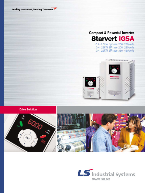
Compact & Powerful Inverter Starvert iG5A0.4~1.5kW 1phase 200~230Volts0.4~22kW 3Phase 200~230Volts0.4~22kW 3Phase 380~480VoltsInverterSTARVERT iG5ALS Starvert iG5A is very competitive in its price and shows an upgraded functional strength. User-friendly interface, extended inverter ranges up to 22kW,superb torque competence and small size of iG5A provides an optimum use environment.StandardcomplianceCompactnessiG5AHighperformanceUser-friendliness& EasymaintenanceOverviewModel & TypeStandard Specifications WiringTerminal Configurations Keypad Features Parameter Setting Trial Run DimensionsBraking Resistors and Peripheral Devices Function ListProtective Functions Fault Remedy48911131516182023253233C o n t e n t siG5A4Powerful & Upgraded Performance iG5A provides sensorless vector control, PID control,and ground-fault protection through powerful built-in functions.The built-in PID function enables to controlflow-rate, oil-pressure, temperature, etcwithout any extra controller.The built-in sensorless vector control providesthe superb speed control and powerful hightorque.Inputting analog signals from -10V to 10Vprovides user-friendly operation.Built-in PID controlAnalog control from -10V to 10VSensorless vector controlCondition:Speed vs Torque CharacteristicsSpeed(Hz)Torque(%)Sensorless Vector Control Mode: Auto tuning Measure maximumtorque (%) at each speed (1/5/10/20/30/40/50/60Hz)+10-10ForwardReverse◀◀The built-in dynamic braking circuit minimizesdeceleration time via braking resistors.Built-in dynamic braking circuitSpeedTimeWith braking resistorReducingdeceleration timePI controlPI controlPI controlPI controlPID controlPID controlPID controlPID controlThe built-in RS-485 communication supportsremote control and monitoring between iG5Aand other equipment.Built-in 485 communicationThe ground-fault protection of output terminalGround-fault protectionduring runningiG5A consists of the product range from 0.4 to 22KW.Wide product range◀Normal state◀Compact & Powerful Inverter iG5A5Checking operation status(Voltage, Current, Frequency, etc)Checking modified parameters Windows supportMonitoringConnected to PCConnected to XGT panelChecking operation timeAutomatic list-up of trip recordLanguage support (Korean, English, Chinese)MonitoringConvenient remote control to modify operation status (Forward/Reverse operation, Frequency, etc)Easy parameter settingAvailable to control up to 31 Inverters RS-485, Modbus communicationRemote ControlConvenient remote control to modify operation status (Forward/Reverse operation, Frequency, etc)Easy parameter settingAvailable to control up to 31 Inverters RS-485, Modbus communication Remote ControlRS-485 -232C converterRS-485 communication6User-friendly Interface & Easy MaintenanceThe parameter setting becomes easier by adopting the 4 directions key. And iG5A supports easy maintenance via diagnosis and fan changeable structure.By controlling the cooling fan, iG5A provides a virtually quiet environment according to the status of operation.iG5ACooling fan controlThe 4 directions key provides easy handling and monitoring.User-friendly interfaceiG5A is designed to be the fan changeable structure in preparation for a fan breakdown.Easy change of fanThe external loader away from a panel enables to control and monitor conveniently. And the parameters made by external loader can be copied and applicable to other Inverters.Loader type + External type (Optional)External loader (Optional)Remarks2m 3m 5mModel nameINV, REMOTE KPD 2M (SV-iG5A)INV, REMOTE KPD 3M (SV-iG5A)INV, REMOTE KPD 5M (SV-iG5A)Through easy parameter setting, iG5A can diagnose the status of output module.Diagnosis of output moduleCompact & Powerful Inverter iG5A7Compact SizeThe compact size achieves cost-efficiency and various applications.Both PNP and NPN inputs become possible and these enable to use the outer power.To do so, users will be given wider choices of selecting the controller.PNP/NPN inputiG5A series complies with CE and UL standards.Global standardGlobal standard compliance CE ULSame height from 0.4 to 4.0kW (128mm)Model & Type8Compact & Powerful Inverter iG5A Standard Specifications1 Phase 200V3 Phase 200V3 Phase 400V1) Indicate the maximum applicable motor capacity when using 4 pole LS standard motor.2) Rated capacity is based on 220V for 200V series and 440V for 400V series.3) Refer to 15-3 of user’s manual when carrier frequency setting (39) is above 3kHz.4) Max. frequency setting range is extended to 300Hz when H40 (Control mode select) is set to 3 (Sensorless vector control).5) Max. output voltage cannot be higher than the input voltage. It can be programmable below input voltage.6) Self-Cooling9Standard Specifications1) Means average braking torque during Decel to stop of a motor.2) Refer to Chapter 16 of user’s manual for DB resistor specification.10Compact & Powerful Inverter iG5A Wiring0.4~7.5kWWiring 11.0~22.0kWCompact & Powerful Inverter iG5A Terminal ConfigurationSpecifications for power terminal block wiringTerminal ConfigurationControl terminal specifications1) Use the recommended tightening torque when securing terminal screws.※When you use external power supply (24V) for multi-function input terminal (P1~P8), apply voltage higher than 12V to activate.※Tie the control wires more than 15cm away from the control terminals. Otherwise, it interferes front cover reinstallation.Compact & Powerful Inverter iG5A Keypad FeaturesMoving to Other Groups Parameter groups1) Target frequency can be set at 0.0 (the 1st code of drive group). Even though the preset value is 0.0, it is user-settable. The changed frequency will be displayed after it is changed.Compact & Powerful Inverter iG5A1) Pressing the Left (◀)/Right (▶)/Up (▲)/Down (▼) key while a cursor is blinking will cancel the parameter value change.Pressing the Ent (●) key in this status will enter the value into memory.※In step 7, pressing the Left (◀) or Right (▶) key while 16.0 is blinking will disable the setting.Trial RunMulti-step operation + Run/Stop via FX/RX + Max. frequency change Operation conditionWiringParameter settingCompact & Powerful Inverter iG5APotentiometer (Volume) + Run/Stop via FX/RX + Accel/Decel time changeOperation conditionWiringParameter settingDimensionsSV004iG5A-2 / SV008iG5A-2, SV004iG5A-4 / SV008iG5A-4SV015iG5A-2 / SV015iG5A-4Compact & Powerful Inverter iG5A SV022iG5A-2 / SV037iG5A-2 / SV040iG5A-2, SV022iG5A-4 / SV037iG5A-4 / SV040iG5A-4SV055iG5A-2 / SV075iG5A-2, SV055iG5A-4 / SV075iG5A-421DimensionsSV110iG5A-2 / SV150iG5A-2 / SV110iG5A-4 / SV150iG5A-4SV185iG5A-2 / SV220iG5A-2 / SV185iG5A-4 / SV220iG5A-422Compact & Powerful Inverter iG5A23Braking Resistors and Peripheral DevicesBraking resistorsBreakers1) The wattage is based on Enable Duty (%ED) with continuous braking time 15sec.Braking Resistors and Peripheral Devices Fuses & AC reactors24Compact & Powerful Inverter iG5A Function ListDrive Group1) This function can be available with iG5A Communication Option Module.25Function ListDrive Group1) Only displayed when one of the Multi-function input terminals 1-8 [I17~I24] is set to “22”.2) It is indicated when H49(PID control selection) is 1.3) This function can be available with iG5A Communication Option Module.Function group 126Compact & Powerful Inverter iG5A271) Only displayed when F 4 is set to 1 (DC brake to stop).2) If H40 is set to 3 (Sensorless vector), Max. frequency is settable up to 300Hz. 3) Only displayed when F24 (Frequency high/low limit select) is set to 1.Function group 1Function List Function group 11) Set F30 to 2(User V/F) to display this parameter.2) Set F50 to 1 to display this parameter.28Compact & Powerful Inverter iG5A Function group 11) It is indicated when setting bit 2 of F59 as 12) Set F63 to 1 to display this parameter.29Function ListFunction group 21) only displayed when H10 is set to 1. # H17, H18 are used when F2, F3 are set to 1 (S-curve) 30Function group 21) Normal acceleration has first priority. Even though #4 is selected along with other bits, Inverter performs Speed search #4.2) H30 is preset based on inverter rating.31Function group 21) H32 ~ H36 factory default values are set based on OTIS-LG motor.2) Set H40 to 3 (Sensorless vector control) to display this parameter. 32331) Set H49 to 1 (PID control) to display this parameter.2) Set H49 as a 13): it is indicated when setting H64(KEB drive select) as a 1 (KEB does not operate when cut power after loading ting input (about 10%).Function group 2Function group 21) Exception: Since SV004iG5A-2/SV004iG5A-4 is Natural convection type, this code is hidden. 34Function group 21) It is indicated when choosing I17~I24 as a 12 (2nd motor select).2) H91,H92 parameters are displayed when Remote option is installed.35Input/output group* See °∞Chapter 14 Troubleshooting and maintenance°±for External trip A/B contact. * Each multi-function input terminal must be set differently.36Input/output group37Input/output group38Input/output group39Input/output group1) It is indicated when choosing I54~I55 as a 19 (Brake signal). 40Compact & Powerful Inverter iG5A Input/output group41Protective Functions42Compact & Powerful Inverter iG5A Fault Remedy43。
山特250kvaups参数
山特250kvaups参数
山特250kVA UPS具有以下参数:
输入电压范围:单相220V / 三相380V。
输出电压:单相220V。
输出频率:50Hz。
额定容量:250kVA。
电池后备时间:1-8小时(可选)。
输入功率因数:≥。
输出功率因数:≥。
转换效率:≥95%。
电池节数:1-32节(可选)。
充电方式:在线式工频设计,配合静态旁路开头,具备完善的过载和故障保护功能。
整流器:12脉冲整流,有效抑制了UPS对电网源造成的谐波污染,提高了UPS的输入功率因数。
监控功能:提供RS232接口及功能强大的监控软件,支持TCP/IP、SNMP 等网络协议,具有先进的远程网络监控功能,采用发送电子邮件或传呼、短信等方式提供实时报警信息等。
显示控制面板:操作简便,一目了然的大屏幕触摸LCD显示控制面板。
控制技术:内置双CPU微处理器,采用直接数字信号控制(DDC)及数字信号处理(DSP)等先进技术,全功能智能数字化控制,包括操作运行、自动关机、实时参数测量显示等。
电池管理:配合独立的电池检测包,通过UPS DB9接口,可检测多达四组的单只电池运行参数,实现真正意义上的电池智能化管理。
其他特性:内置手动维修旁路开关。
具有很宽的电压输入范围,减少电池运行机会,延长电池寿命。
请注意,具体的参数可能会根据不同版本和配置有所不同,建议查阅产品说明书或联系厂家获取准确信息。
315变压器参数

315变压器参数变压器是一种将电能由一种电压转换为另一种电压的电气设备。
315变压器是一种常见的变压器型号,下面将介绍315变压器的参数和特点。
1. 额定容量:315变压器的额定容量是指在额定工作状态下所能输出的最大功率。
315变压器的额定容量通常为315千伏安(KVA),也有其他额定容量的变压器,如10KVA、100KVA等。
2. 额定电压:315变压器的额定电压是指变压器的输入和输出电压。
一般情况下,变压器的输入电压称为高压侧电压,输出电压称为低压侧电压。
315变压器的额定电压通常为10KV(千伏)和0.4KV (千伏),也有其他额定电压的变压器。
3. 频率:315变压器的频率是指电能转换的周期数,通常为50赫兹(Hz)或60赫兹(Hz)。
4. 绝缘等级:315变压器的绝缘等级是指变压器的绝缘能力。
绝缘等级越高,变压器的绝缘能力越强,安全性越高。
315变压器的绝缘等级通常为F级或H级。
5. 联结组别:315变压器的联结组别是指变压器的绕组连接方式。
常见的联结组别有Yyn0、Yd11、Dyn11等。
不同的联结组别适用于不同的电力系统和负载类型。
6. 空载损耗:315变压器的空载损耗是指在无负载情况下,变压器的损耗功率。
空载损耗通常用电压平方乘以空载电流得到。
7. 短路阻抗:315变压器的短路阻抗是指在短路状态下,变压器的阻抗大小。
短路阻抗越大,变压器的短路能力越强。
8. 外形尺寸:315变压器的外形尺寸是指变压器的外部尺寸。
外形尺寸通常包括长度、宽度、高度等。
315变压器具有以下特点:1. 高效率:315变压器采用优质的硅钢片和绝缘材料,使得变压器的能效达到较高水平,减少能源的浪费。
2. 节能环保:315变压器具有较低的空载损耗和负载损耗,能够节约能源,并减少对环境的污染。
3. 可靠性高:315变压器采用优质的材料和先进的制造工艺,具有良好的绝缘性能和稳定的运行,能够长时间稳定工作。
4. 体积小:315变压器采用紧凑的设计和合理的结构,使得变压器的体积较小,适用于空间有限的场所。
拓谟吾Crane Group L系列吊车型号L70、L65、L60、L55、L50、L45、L40、

Maximum Capacity 26,455 lbs-------------235'-4'-------------binI---59'-1" ----IJI II---39'-4"P60ANote: Tip capacities are dependent on certain trolley types.L70L65 = 213'-3'L60 = 196'-10"L55 = 180'-5'_l229'-8' --17,055 lbs8,4881bs9,354 lbsL50 = 164'-1"10,382 lbsL45 = 147-8"11,905 lbsL40 = 131'-3'13,228 lbsL35 = 114'-10'14,991 lbsL30 = 98'-5'17,747 lbs21,385 lbstV60A Y800At�in--j 32'-10' I-J850AF.E.M. 1.001Maximum Free-Standing Hook HeightsMechanical Data2-part (lifting)4-part (lifting)Function HoistTypeSpeed vs Weight 1st Gear 2nd Gear 3rd Gear 4th Gear 5th Gear 1st Gear 2nd Gear 3rd Gear 4th Gear 5th Gear Motor (hp)Motor (kW)Rope Length (ft)50 LVF 30Optimaft/min lbs 9913,2281259,9211786,6142563,3075026,4556319,8428913,2281286,61450371,11575 LVF 30Optimaft/min lbs 14513,2281849,9212636,6143753,3077326,4559219,84213213,2281886,61475551,870100 LVF 30Optimaft/min lbs 19713,2282509,9213556,6145193,3079926,45512519,84217813,2282606,614100751,926or 3,343150 LCC 30ft/minlbs28313,2283389,9214246,6145653,3076761,65314226,45517119,84221413,2282836,6143383,3071501102,139Trolley 6 DVF 4ft/min 5.5 4.0Swing RVF 162Optima rpm 2 x 7.5 2 x 5.5P o w e r R e q u i r e m e n t s :480V (+6%o r -10%)60H z m e a s u r e d a t t u r n t a b l e .A m p e r a g e :50L V F 30:88A m p (3p h a s e s e r v i c e w i t h g r o u n d )A m p e r a g e :75L V F 30:118A m p (3p h a s e s e r v i c e w i t h g r o u n d )A m p e r a g e :100L V F 30:147A m p (3p h a s e s e r v i c e w i t h g r o u n d )A m p e r a g e :150L C C 30:245A m p (3p h a s e s e r v i c e w i t h g r o u n d )Notes:1. The 50 LVF 30 is the standard hoist option for the MD 310B-K12. Other hoist options must be at the request of the customer.2. Hoist speeds with "Optima" hoist units are 25% faster than the speeds listed above when lowering the hook.3. The 100 LVF 30 hoist drum can be purchased in either a small or large drum size depending on the customers needs.4. Values given under "Rope Length" are for drum spooling capacity only.Hoist165 (26,455 lbs) 329 (13,228 lbs) 394 (6,614 lbs)0.70Rated Load Chart C a p a c i t y (l b s )229'-8"213'-3"196'-10"180'-5"164'-1"147'-8"131'-3"114'-10"98'-5"20'-0"26,45526,45526,45526,45526,45526,45526,45526,45526,45530'-0"26,45526,45526,45526,45526,45526,45526,45526,45526,45540'-0"26,45526,45526,45526,45526,45526,45526,45526,45526,45550'-0"26,45526,45526,45526,45526,45526,45526,45526,45526,45560'-0"26,45526,45526,45526,45526,45526,45526,45526,45526,45570'-0"26,45526,45526,45526,45526,45526,45526,45526,45526,45580'-0"22,97824,57024,82424,83125,37325,98526,45526,45526,45590'-0"19,93721,37221,62221,62822,10822,65023,56323,69023,77998'-5"17,86619,19519,44219,44819,886 20,380 21,213 21,32921,385100'-0"17,51918,83019,07619,08219,51320,00020,81920,933110'-0"15,55116,76017,00417,00917,40017,84218,58518,688114'-10"14,72615,89316,13616,14016,515 16,937 17,64817,747120'-0"13,91715,04315,28515,28915,647 16,051 16,731130'-0"12,94413,59413,83513,83914,16914,54115,167131'-3"12,78913,43113,67213,67614,002 14,37114,991140'-0"11,76712,76213,00013,00113,228 13,250147'-8"10,97711,93112,16812,17012,46312,787150'-0"10,74911,69211,92911,93012,218160'-0"9,86110,75710,99310,99511,265164'-1"9,53310,41310,64810,64910,913170'-0"9,0799,93510,17010,171180'-0"8,3849,2059,4399,440180'-5"8,3559,1749,4089,409190'-0"7,7648,5538,786196'-10"7,3768,1458,378200'-0"7,2077,966210'-0"6,7037,437213'-3"6,5507,275220'-0"6,246229'-8"5,842M a x .L o a d R a d i u s F r o m8'-6"8'-6"8'-6"8'-6"8'-6"8'-6"8'-6"8'-6"8'-6"T o71'-1"75'-1"75'-9"75'-9"77'-2"78'-9"81'-6"81'-10"82'-2"Notes:1. The above load chart was calculated using the SM-DM trolley system.2. Values above the red line can be achieved with 4-part line configuration only.3. Deduct 551 lbs from values below the red line when using 4-part line configuration instead of 2-part.H o o kR a d i u sRated Load Chart 2-P a r t C a p a c i t y (l b s )229'-8"213'-3"196'-10"180'-5"164'-1"147'-8"131'-3"114'-10"98'-5"20'-0"13,22813,22813,22813,22813,22813,22813,22813,22813,22830'-0"13,22813,22813,22813,22813,22813,22813,22813,22813,22840'-0"13,22813,22813,22813,22813,22813,22813,22813,22813,22850'-0"13,22813,22813,22813,22813,22813,22813,22813,22813,22860'-0"13,22813,22813,22813,22813,22813,22813,22813,22813,22870'-0"13,22813,22813,22813,22813,22813,22813,22813,22813,22880'-0"13,22813,22813,22813,22813,22813,22813,22813,22813,22890'-0"13,22813,22813,22813,22813,22813,22813,22813,22813,22898'-5"13,22813,22813,22813,22813,22813,22813,22813,22813,228100'-0"13,22813,22813,22813,22813,22813,22813,22813,228110'-0"13,22813,22813,22813,22813,22813,22813,22813,228114'-10"13,22813,22813,22813,22813,22813,22813,22813,228120'-0"13,22813,22813,22813,22813,22813,22813,228130'-0"13,22813,22813,22813,22813,22813,22813,228131'-3"13,22813,22813,22813,22813,22813,22813,228140'-0"12,96113,22813,22813,22813,22813,228147'-8"12,17313,13113,13013,13113,22813,228150'-0"11,94612,89212,89112,89213,208160'-0"11,06111,96011,96011,96112,256164'-1"10,73411,61611,61611,61711,905170'-0"10,28111,14011,13911,140180'-0"9,58910,41210,41110,412180'-5"9,56010,38110,38110,382190'-0"8,9719,7629,761196'-10"8,5849,3559,354200'-0"8,4159,177210'-0"7,9138,649213'-3"7,7608,488220'-0"7,457229'-8"7,055M a x .L o a d R a d i u s F r o m10'-2"10'-2"10'-2"10'-2"10'-2"10'-2"10'-2"10'-2"10'-2"T o 137'-7"146'-8"146'-8"146'-8"149'-10"147'-8"131'-3"114'-10"98'-5"H o o kR a d i u sRated Load Chart 4-P a r t C a p a c i t y (l b s )229'-8"213'-3"196'-10"180'-5"164'-1"147'-8"131'-3"114'-10"98'-5"20'-0"26,45526,45526,45526,45526,45526,45526,45526,45526,45530'-0"26,45526,45526,45526,45526,45526,45526,45526,45526,45540'-0"26,45526,45526,45526,45526,45526,45526,45526,45526,45550'-0"26,45526,45526,45526,45526,45526,45526,45526,45526,45560'-0"26,45526,45526,45526,45526,45526,45526,45526,45526,45570'-0"26,45526,45526,45526,45526,45526,45526,45526,45526,45580'-0"22,66924,48524,48524,48525,08425,70026,45526,45526,45590'-0"19,63721,29521,29521,29521,82622,37223,34723,47223,55998'-5"17,57319,12419,12419,12419,60920,10620,99621,11021,164100'-0"17,22618,76018,76018,76019,23619,72620,60120,714110'-0"15,26416,69616,69616,69617,12817,57218,36618,468114'-10"14,44115,83115,83115,83116,24416,66917,42917,527120'-0"13,63514,98314,98314,98315,37915,78516,511130'-0"12,26213,53913,53913,53913,90314,27814,947131'-3"12,10813,37613,37613,37613,73714,10814,771140'-0"11,08912,30512,30512,30512,64312,990147'-8"10,30111,47611,47611,47611,79712,125150'-0"10,07411,23811,23811,23811,553160'-0"9,18910,30610,30610,30610,601164'-1"8,8629,9629,9629,96210,250170'-0"8,4099,4869,4869,486180'-0"7,7178,7588,7588,758180'-5"7,6888,7278,7278,727190'-0"7,0988,1088,108196'-10"6,7117,7017,701200'-0"6,5437,523210'-0"6,0406,995213'-3"5,8876,834220'-0"5,584229'-8"5,182M a x .L o a d R a d i u s F r o m10'-2"10'-2"10'-2"10'-2"10'-2"10'-2"10'-2"10'-2"10'-2"T o 70'-4"74'-11"74'-11"74'-11"76'-5"78'-0"80'-11"81'-3"81'-7"H o o kR a d i u sManitowoc Crane Group - Americas Shady Grove, Pennsylvania Facility1565 Buchanan Trail EastShady Grove, PA 17256-0021, USATel:[Int + 001] 717 597 8121Fax:[Int + 001] 717 597 4062。
美国海利威尔公司V15系列微型基本开关说明书

V15 SERIESMICRO SWITCH Standard Miniature Basic Switches004945Issue 12DESCRIPTIONHoneywell’s MICRO SWITCH V-Basic Standard Switch, V15 Series is anelectromechanical switch designed to provide outstanding value in a reliable global package. This switch is often ideal for “low-cost-of-failure” applications, where the cost is minimal to replace or service any failure related to the switch. With a wide variety of operating forces, and amperage ratings, the V15 is designed for numerous types of applications.Available in both pin plunger and levered styles, the V15 Series also offers a multitude of termination styles to fit almost any application.DIFFERENTIATION• Choice of actuation, termination, and operating characteristics that can allow for flexibility in numerous types of applications• With a broad current capacity, one switch package can control a wide range of electrical loadsAPPLICATIONS• Appliances • Furnaces• Gaming machines • Ice makers • Power washers • Vending machinesVALUE TO CUSTOMERS• Wide choice of electrical ratings: 0.1 A, 5 A, 10 A, 16 A, 22 A, 26 A • Certified for global use: UL/cUL, ENEC, CQC• Available with pin plungers or integral levers to meet multiple application and equipment requirementsFEATURES• Broad range of electrical loads: 0.1 A, 5 A, 10 A, 16 A, 22 A, 26 A • Long service life: over one million mechanical operations• Gold contacts are also available for controlling logic level/low energy circuits• World-wide package size acceptance • UL/CSA, cUL, ENEC, and CQC approvals• Variants with cadmium-free and optimized contacts availableHoneywell offers a wide range of MICRO SWITCHthe large basic switches,Sensing and Internet of Things 3V15S05 PRODUCT NOMENCLATURE V15Switch TypeTemperatureGradeSLeverPositionElectrical Rating05V15 Series Standard Basic SwitchTerminal TypeCircuit Code—ZAOperating Force(at pin plunger max)200Mounting HolesKALever Type06Special DesignatorC—Housing Type1V15T10 PRODUCT NOMENCLATUREV15Switch TypeTemperatureGradeTLever PositionElectrical Rating10V15 Series Standard Basic SwitchTerminal TypeCircuit Code—ZAOperating Force(at pin plunger max)200Mounting HolesKALever Type06A special designator letter is used only when there is a special modificationto the switch.Review Product Specification to determine the exact differences. Below is an example.Special DesignatorC—Housing Type1V15H16/T16/T22/H22/T26 PRODUCT NOMENCLATURE V15Switch TypeTemperatureGradeHLever PositionElectrical Rating16V15 Series Standard Basic SwitchTerminal TypeCircuit Code—ZAOperating Force(at pin plunger max)200Mounting HolesKALever Type06Special DesignatorC—Housing Type1PinPlunger4 ShortStraightLeverStandardStraightLeverSensing and Internet of Things 5LongStraightLeverSimulatedRoller6 ShortRollerLeverSensing and Internet of Things 7RollerLever8 Sensing and Internet of Things 9MOUNTING DIMENSIONSFIGURE 1. V15 SERIES STANDARD SWITCH DIMENSIONSFIGURE 2. V15 SERIES METRIC MOUNTING HOLE DIMEN-SIONS FOR Ø 3 MM PINS OR SCREWSMetric mounting for Ø 3 mm pins or screws Ø 3,10 mm +0,10 mm/-0,05 mm 10,3 m m ±0,1 m m Ø 0.12 in +0.004 in/-0.002 in mounting holeFIGURE 3. V15 SERIES USA MOUNTING HOLE DIMENSIONS FOR #4 SCREWSUS mounting for #4 screws - K Designator Ø 2,90 mm +0,10 mm/-0,05 mm10,3 m m ±0,1 m m Ø 0.11 in +0.004 in/-0.002 in mounting holeFIGURE 4. V15 SERIES HOUSING DIMENSIONS10 Sensing and Internet of Things 1112 STANDARD LEVER OPTIONS • DIMENSIONSFIGURE 19. V15 SERIES A01/STRAIGHT SHORT LEV erFIGURE 20. V15 SERIES A02/STANDARD STRAIGHT LEVERFIGURE 21. V15 SERIES A03/LONG STRAIGHT LEVERFIGURE 22. V15 SERIES A04/SIMULATED ROLLER LEVERFIGURE 23. V15 SERIES A05/SHORT ROLLER LEVERFIGURE 24. V15 SERIES A06/ROLLER LEVERNOTE: These dimensions apply for the “A” lever position. For the “B” leverposition, please add 5,7 mm [0.224 in].Position APosition BWARRANTY/REMEDYHoneywell warrants goods of its manufacture as being free of defective materials and faulty workmanship during the applicablewarranty period. Honeywell’s standard product warranty applies unless agreed to otherwise by Honeywell in writing; please refer to your order acknowledgment or consult your local sales office for specific warranty details. If warranted goods are returned to Honeywell during the period of coverage, Honeywell will repair or replace, at its option, without charge those items that Honeywell, in its sole discretion, finds defective. The foregoing is buyer’s sole remedy and is in lieu of all other warranties, expressed or implied, including those of merchantability and fitness for a particular purpose. In no event shall Honeywell be liable for consequential, special, or indirect damages.While Honeywell may provide application assistance personally, through our literature and the Honeywell web site, it is buyer’s sole responsibility to determine the suitability of the product in the application.Specifications may change without notice. The information we supply is believed to be accurate and reliable as of this writing.However, Honeywell assumes no responsibility for its use.004945-12-EN | 12 | 08/20© 2019 Honeywell International Inc. All rights reserved.m WARNINGIMPROPER INSTALLATION• Consult with local safety agenciesand their requirements whendesigning a machine-control link, interface and all control elements that affect safety.• Strictly adhere to all installationinstructions. Failure to comply with theseinstructions could result in death or serious injury.m WARNINGMISUSE OFDOCUMENTATION•The information presented in this product sheet is for reference only. Do not use this document as a product installation guide.•Complete installation, operation, and maintenance information is provided in the instructions supplied with each product.Failure to comply with theseinstructions could result in death or serious injury.HoneywellSensing and Internet of Things 830 East Arapaho Road Richardson, TX FOR MORE INFORMATIONHoneywell Sensing and Internet of Things services its customers through a worldwide network of sales offices and distributors. For application assistance, current specifications, pricing, or the nearest Authorized Distributor, visit or call:USA/Canada +302 613 4491Latin America +1 305 805 8188Europe +44 1344 238258Japan +81 (0) 3-6730-7152Singapore +65 6355 2828Greater China+86 4006396841RELATED DOCUMENTATIONThe following associated literature is available on the Honeywell web site at :• Installation instructions• Product part listing/nomenclature tree• Product application-specific information– Application note: Electronic sensorsand eectromechanical switches in valves and flow meters – Application note: Electronic sensorsand MICRO SWITCH switches in industrial air compressors – Application note: Sensors andswitches for potential HVAC/R applications – Application note: Sensors andswitches for valve monitors and valve indicators – Application note: Sensors andswitches in sanitary valves – Case study: Switching it up– Technical bulletin: Applying precision switches。
1万多个电视机高压包脚位通法
334P12902 334P12903 三棱25″ 三棱25″ MITSUBISHIK 25C-SS1 334P12903 三棱25″ MITSUBISHIK 25C794 334P12903 F 1130 三洋6920 20″ 三洋6920 20″ F 1130 F 1117 三洋4505 16″ 三洋4505 16″ F 1117(B) F1117(B) 三洋450516″ BSC23-0101 金利浦14″ 金利浦14″ BSC23-0101 FCM-2012E21A 37M2012E-21A BSC21-3366 孔雀14″ BSC23-3366 孔雀14″ BSC21-3366 BSC23-3366 BSC23-3366 优纳拉斯14″ 孔雀14″ TFB-3035B 康艺8135 康艺4507 康艺4507 TFB-3035B 康艺8135 康艺8135 TFB-3035B BSC24-1051P 熊猫2118 2119 2128 熊猫54P36 熊猫2118 2119 2128 熊猫54P36 BSC24-1051P BSC22-2501B 康艺CE3703 凯歌4C370S 康艺CE3703 BSC22-2501B 凯歌4C370S 凯歌4C370S BSC22-2501B 康艺CE3703 TLF15550B DNF.FL2732A 2027017-001 53X0528-001 53X0528-001 2027017-001 假松下TC-2198 730-302-1548 39L7014AI 79A316-2 TLF70100 TLF70100 79A316-2 ATK1061 三棱40″ 三棱40″ ATK1061 BSC25-2951C 金星C542 金星C542 BSC25-2951C BSC26-N0401 TFB 4095BD 金星C6428
T1AL250V(大威)
5、电气特性 5.1 测试条件 全部测试条件都应在环境温度 24˚C+/-3˚C 条件下进行,在此期间温度变化不允许达到 +5˚C 和到极限范围。 5.2 负载能力测试 当保险丝通以 100%倍额定电流的条件下进行测试时,在 4 小时内电路不应断开,保险 丝不被电流熔化,管壳不破裂。
产品规格承认书
客户名称:
SPECIFICATION FOR APPROVAL
欣锐特
文件编号:DW-QF-113
CUSTOMER:
产品名称:
玻璃管保险丝
PRODUCT NAME:
型号:
3.6X10MM
MODEL DETAIL:
规格:
3.6X10MM 保险丝(慢断)T1AL250V
SPECIFICATION:
SUPPLIER:
CUSTOMER:
日期:
日期:
DATE: 2009-11-07
DATE:
备注:承认签章后请回复一份承认书(或复印件)给我司,如果在签章的承认书(或复印件)回复给我
司之前,下了有关此零件的订单且又无特别说明,那么我司就确定贵司已完全承认了。
Page:1 OF 3
1.适应范围
本规格书适用于公司按 ○大 CCC 安全标准认证的小型保险丝管。
2.原材料规格:
NO. 1 2 3 4
部件 铜帽 玻璃管 可熔体 尾线
材
料
黄铜(镀镍)
玻璃
合金纤维绕丝
黄铜(镀锡)
3.尺寸与结构 3.1 主体尺寸如图所示:(单位:MM)
3.2 玻璃管 玻璃管无破裂、缺损或污染现象,且须透明易辨其内部的可熔体。
Eaton 3S550产品说明说明书

Eaton 3S550ASC 3S Eaton, 550 VA, 330 W, entrée 5-15P, Prises : (4) 5-15R,(4) 5-15R surtension uniquementSpécifications généralesASC 3S Eaton3S55074317203462513.2 in3.4 in 5.5 in7.3 lb FCC Partie 15 Classe A Sous-partie BSections 15.107b, 15.109bNOM Homologué cUL UL 1778UL 497A SÉRIE 3, Batteries remplaçables par l’utilisateur.Nom du produit Numéro du catalogue CUP Longueur du produit Hauteur du produit Largeur du produit Poids du produit Conformités Certifications Notes de catalogueGraphique sur la durée d'exécution Remplaçable par l’utilisateur 1Scellé, plomb-acide (4) 5-15R, (4) 5-15R surtension uniquement 0,6102 à 132 Vca 0,1 Hz Hors ligne/en veille5-15P57 à 70 Hz(1) port USB OuiJusqu'à 10 000 pi (3 000 m) sans déclassement < 50 dB à 1 mètre 0 ° à 40 °C (32 ° à 104 °F)De 20 à 93 % sans condensation1 ASC prête à fonctionner, Câble USB, Guide de l’utilisateur Noir 97 %OuiEaton 3S UPS Graphique sur la durée d'exécution Remplacement de batterie Quantité de batteries Type de batterie ReceptacleFacteur de puissance de sortie Plage de tension de sortie Fréq. de sortie TopologieConnexion d'entrée Plage de fréquences d'entrée Communication Interface Ethernet AltitudeNiveau de bruit Plage de température Humidité relativeContenu de l’emballageCouleur EfficacitéProtection contre les surtensions Plans de services étendus Audiovisuel BrochuresÉCHANGE DE DÉPÔT AVANCÉEaton Corporation plc Eaton House30 Pembroke Road Dublin 4, Ireland © 2023 Eaton. Tous droits réservés. Eaton is a registered trademark.All other trademarks areproperty of their respectiveowners./socialmedia Eaton 3S UPS brochureEaton 3S technical specificationsEaton load protection guaranteeEaton extended warranty certificateEaton limited warrantyExtended warranty certificateEaton 3S UPS user guideCaractéristiquesGuides de garantieManuels et guides d’utilisationDÉPÔT POUR LARÉPARATION DE CINQ ANS : 3SW5Y-0750UC- Couv. sur les piècesexpédiées pendant cinq ans - Couv. des pièces, des appareils électroniques et des batteries de l’ASC- Expédition le prochain jour ouvrable- Soutien technique。
Rocktron Velocity 250 吉他电力放大器说明书

G U I T A R P O W E R A M P L I F I E RU S E R'S M A N U A LMay be covered by one or more of the following:U.S. Patents #4538297, 4647876, 4696044, 4745309, 4881047, 4893099, 5124657, 5263091, 5268527, 5319713, 5333201, 5402498 and 5493617.Other patents pending. Foreign patents pending.Copyright ©1996 Rocktron Corporation.All rights reserved.! WARNING !The Velocity ® 250 is capable of producing extremely high sound pressure levels. The use of ear protection is essential in situations when prolonged exposure to such high sound pres-sure levels occurs. Failure to use caution and/or ear protection when using this amplifier may result in permanent hearing impairment or hearing loss. United States Government guidelines concerning safe noise exposure levels should be referred to before operating the amplifier at high levels. The manufacturer is not responsible for any damage resulting from the use of this product.UNPACKING Upon unpacking the Velocity ® 250, save the carton and all the packing materials in case it becomes necessary to ship the unit.Be sure to thoroughly inspect your unit and its carton for any signs of damage that may have occurred during shipment. If there are any signs of damage, contact your dealer immedi-ately.INSTALLATION When installing the Velocity ® 250 in your rack, it is best for ventilation and heat dissipation that the unit occupy the bottom space of your rack. It is also recommended that a vacant space is left above the power amp, if possible, to further improve ventilation.OPERATING TEMPERATURE Do not expose this unit to excessively warm or cold temperatures. This unit is designed to operate between 32°F and 104°F (0°C and 40°C). This unit may not function properly under extreme conditions.ContentsIntroduction (1)Velocity 250 Design (2)Front Panel (3)Rear Panel (4)Connections (5)Stereo Applications (5)Mono Bridged Applications (6)Operating Precautions (7)Power Output/Speaker Load (7)Fuse Replacement (8)Other Features (9)Automatic Short Detection (9)Definition Control (9)Specifications (10)IntroductionCongratulations on your purchase of the Velocity® 250 guitar power amplifier! TheVelocity 250 was designed to provide the greatest flexibility with the highest reliability,even under extreme operating conditions. This 2-rackspace amp will provide 125watts/channel when used in stereo applications or 250 watts mono bridged into a 8ohm load—without a cooling fan!The Velocity 250 has a unique "Reactance" circuit that actually replicates theoutput impedance of tube amplifiers—so you can get the same great sound that a tubeamplifier delivers in a reliable solid state design. And, because it is a variable control,you can customize your Velocity 250 to sound like any of your favorite tube amps. Bestof all, this feature is available in the mono bridged mode too!In addition, the Velocity 250 has "Definition" controls to give you that little bit ofedge you need to bring your playing out in the mix. It also has automatic short circuitprotection, which detects problems and shuts down the amplifier before any internaldamage can be done. It also has massive heatsinks for cool, reliable performance.Other Features:•115/230 VAC voltage selector switch.•An AC power detect circuit, which ensures that the amplifier outputsshut down first when AC is removed. This will guard against anythumps or pops that could otherwise occur, potentially damagingspeakers when power is cut to the amplifier.•Differential input buffers to eliminate ground loop hum coming from thepower amp.•Over-temperature protection•Rock-solid design to provide reliable, trouble-free use.1Velocity 250 Design®Designers have been working at creating solid state amplifiers which sound liketube amplifiers ever since the transistor hit the scene. We at Rocktron first producedthe Velocity 150 & 300 amplifiers with that goal in mind. The Velocity 250 takes whatthose first models provided to a whole new level.Every tube amplifier has some amount of output impedance due to the outputstepdown transformer. Conversely, solid state amplifiers have little or no outputimpedance, because the speaker terminals are connected directly to the outputdevices. This difference in impedance is the primary reason why the two types ofamplifiers sound differently. The reason the output impedance makes such a differ-ence is because these amplifiers get connected to speakers (which also have theirown impedance curves), not 4 or 8 ohm resistors. When a tube amplifier drives aspeaker—each with its own characteristic impedance—they react to each other (i.e.one will effect what the other is doing). This is not the case with solid state amps—atleast, not until now!The engineers at Rocktron have developed a circuit which actually measures aspeaker’s impedance and changes the output response of an amp to match what youwould hear from a tube amplifier—automatically! After developing this circuit, the onlyquestion that remained was "Which tube amp do we design to match to, since eachone is different?". We came back and said "ALL of them!". By giving you a variableREACTANCE control, you control the amount of effective* output impedance of theVelocity 250 to match any number of tube amplifiers. With the REACTANCE controlat the minimum setting, a very low output impedance is simulated—similar to a goodsolid state amplifier. As the control is turned clockwise, the effective impedanceincreases and sounds more like a tube amplifier’s output stage.*Note:The word "effective" is used because if we actually increased the outputimpedance to, say 2 ohms for example, and had a 2 ohm speaker cabinet(for a total of 4 ohms), we would lose one half of the power before it evengot to the speaker! That means our 125 watts/channel would only begood for 62 watts/channel. But with the Velocity 250, you still get the fullrated output delivered to the speaker.What this means for you is that you get an amplifier that will react differently witheach speaker cabinet you use with it, just like a tube amp would do. Plus, you get tocontrol how much reactance you want to tailor fit the sound to your needs. TheREACTANCE control in conjunction with the DEFINITION control gives you anincredible amount of flexibility that few amps on the market can touch. And, if you arereally power hungry and want to mono bridge your amp, you won’t sacrifice any ofthese features. Plus, with the massive heatsinking available on this amplifier, youwon’t have to worry about heat issues.23This switch powers up the Velocity 250.This control determines the output level for Channel 1.This control determines the amount of Reactance for Channel 1. As this controlis turned clockwise, the simulated output impedance is increased and theVelocity 250 will increasingly exhibit the characteristics produced by the interac-tion between a tube amplifier and a guitar speaker cabinet. When turned fullycounterclockwise, the simulated output impedance is at a minimum.This control determines the level of definition for Channel 1. Turning this controlfully counter-clockwise bypasses the Definition circuit, while turning it fullyclockwise provides maximum Definition.When switched to "BRIDGED" the Velocity 250 operates as a mono unit withincreased output power (Channel 2 becomes inoperable in this condition).In the "STEREO" position the unit operates as a normal stereo amplifier.This control determines the output level for Channel 2.This control determines the amount of Reactance for Channel 2. As this controlis turned clockwise, the simulated output impedance is increased and theVelocity 250 will increasingly exhibit the characteristics produced by the interac-tion between a tube amplifier and a guitar speaker cabinet. When turned fullycounterclockwise, the simulated output impedance is at a minimum.This control determines the level of definition for Channel 2. Turning this controlfully counter-clockwise bypasses the Definition circuit, while turning it fullyclockwise provides maximum Definition.1 POWER switch2 GAIN control3 REACTANCE control4 DEFINITION control5 STEREO/BRIDGED switch6 GAIN control7 REACTANCE control8 DEFINITION control1 INPUT jack (Ch. 2)2 OUTPUT jacks (Ch. 2)3 115/230 selector switch4 OUTPUT jacks (Ch. 1)5 INPUT jack (Ch. 1)6 POWER INLET module This standard ¼" jack provides an input to Channel 2 from the output of your preamp or the last device in your effects chain.This jack is inoperable when using the Velocity 250 in "bridged" mode (i.e STEREO/BRIDGED switched to "BRIDGED").These standard ¼" jacks provide outputs for Channel 2 to speaker cabinets. Do not connect these outputs to a load of less than 4 ohms (or less than 8 ohms in mono-bridged mode). These jacks are inoperable when using the Velocity 250 in "bridged" mode (i.e STEREO/BRIDGED switched to "BRIDGED").This switch allows for easy setup between 115VAC and 230VAC.Warning: Improper setting of this switch may causethe unit to fail. Make sure the switch setting matchesthe local AC mains voltage.These standard ¼" jacks provide outputs for Channel 1 to speaker cabinets. Do not connect these outputs to a load of less than 4 ohms (or less than 8 ohms in mono-bridged mode). These jacks are used when using the Velocity 250 in "bridged" mode.This standard ¼" jack provides an input to Channel 1 from the output of your preamp or the last device in your effects chain.This jack is used as the input jack when operating the Velocity 250 in "bridged" mode.This module provides a connection for the power cord and also houses the main fuse of the unit. (For information about changingthe fuse, see page 8).4ConnectionsStereo Applications5Mono Bridged Applications67Operating PrecautionsAlthough operation of the Velocity 250 is simple once the proper connectionshave been made, attention to the following precautions is essential to protect your equipment against failure and ensure the long life of your Velocity ® amplifer.Power Output/Speaker LoadThe Velocity 250 is capable of producing the following power output levels into each of these loads:Unbridged (Stereo)4Ω load 125 watts8Ω load 90 watts16Ω load 50 watts (with both channels driven)Bridged (Mono)4Ω load Not Recommended*8Ω load 250 watts16Ω load 170 watts!Always be certain to use speakers or speaker cabinets capable ofwithstanding the power provided in the above mentioned applications.Rocktron is not responsible for speaker failure resulting from use of this equipment.!Never connect 2 outputs of the amplifier to the same speaker. Thiswould be equivalent to shorting the outputs of the amplifier togetherand would shut the unit down immediately.!Plug and unplug speaker outputs with the power amplifier OFF to avoidover-current shutdown of the unit. (See page 9 for information on Automatic Short Detection.)* Note:Rocktron does not recommend using the Velocity 250 in bridged mode whenconnected to a load of less than 8 ohms. However, using the Velocity 250 inbridged mode with an 8 ohm load produces a higher output level (250 watts)than would be achieved with a 4 ohm load - therefore using a 4 ohm loadwould provide no additional benefits.Fuse ReplacementAlways replace the main fuse with an identically rated replacement. Your Velocity 250 amplifier uses a 5x20mm, 5A amp, 250V slow-blow fuse (2.5A, 250V slow-blow for 230VAC). The fuse is located immediately below the line cord inlet on the rear panel and can be accessed by removing the fuse cover module as shown below.Note: A small compartment is also provided within the fuse cover module for storing aspare fuse.Use a small flat screwdriver as shown to slide the fuse cover out from the power inlet module.The fuse can be found inside the fuse cover module after it is pulled out.After replacing the fuse with another of identical specifications, push the fuse cover module fully back into place, ensuring that the fuse has snapped onto the fuse holder inside the power inletmodule.G8Other FeaturesAutomatic Short DetectionA feature truly unique to the Velocity line of power amps is Automatic ShortDetection circuitry. Typically, shorting the outputs of a high output power amplifier willcause amplifier failure and severely damage internal components. The AutomaticShort Detection circuit in the Velocity 250 will automatically detect any shorts whichmay inadvertently occur across the amplifier's outputs and immediately shut down theunit to protect it against internal damage.Should this condition occur, switch the unit off for approximately 10 seconds andmake sure that the cords from the amplifier outputs are properly connected. When thepower is turned on again with the proper connections, the amplifier will operatenormally. It is important to note that two outputs from the amplifier should never beconnected to the same speaker, as this would be equivalent to shorting the outputstogether and will cause the unit to shut down.In the unlikely event that the proper connections have been made and the unit stillshuts down, we strongly recommend that you first contact our Customer SupportDepartment at the phone or fax number shown on the back cover of this manualbefore taking the unit to a dealer or repair shop for servicing.Definition ControlWhen playing with other musicians, it often becomes a problem that the guitarcan get "buried" under the other instruments and cannot be distinguished easily. Thefront panel Definition control gives the effect of bringing the guitar out of the cabinetso that it can be heard despite the other instruments. Although it does not actuallyeffect the volume of the amplifier, the Definition control can be adjusted so that theguitar becomes more audible when playing with a band.Turning the Definition control fully counterclockwise bypasses the definitioncircuit, while turning it fully clockwise provides maximum definition.910SpecificationsOutput Power (Unbridged)(Bridged)Input Sensitivity Maximum Input Level Maximum Output Level Maximum Gain Noise Floor Dynamic Range Distortion (Typical)Frequency Response Current Consumption125 watts per channel @ 4Ω (both channels driven)90 watts per channel @ 8Ω (both channels driven)50 watts per channel @ 16Ω (both channels driven)250 watts @ 8Ω170 watts @ 16Ω-7.3dBu (0.335V RMS), 4Ω stereo for rated output at max. gain 23dBu (10.95V RMS), input stage clip point35dBu (4Ω bridged)36dB-75dBu typical (referenced to 1 watt)95dB0.1% THD20Hz - 20KHz, +0/-3dB5 amps @115VAC max. (575 watts)Rocktron Corporation 2870 Technology Drive Rochester Hills, MI 48309Customer Service:(810) 853-5150Fax Number:(810) 853-5937。
DW15系列万能式断路器主要技术参数
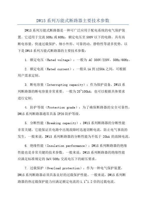
DW15系列万能式断路器主要技术参数DW15系列万能式断路器是一种可广泛应用于配电系统的电气保护装置。
它适用于交流50Hz或60Hz,额定电压至500V以下的电路。
具有高断电容量、快速过载保护、细小外形、可靠的动、静特性等诸多优势。
以下是DW15系列万能式断路器的主要技术参数:1. 额定电压(Rated voltage):一般为AC 380V/220V,50Hz/60Hz。
2. 额定电流(Rated current):一般从1A到1250A之间,可根据用户需求定制。
3. 断电容量(Interrupting capacity):作为保护设备,DW15系列断路器的断电容量非常重要。
一般为20~100kA,也可以根据具体要求进行定制。
4. 防护等级(Protection grade):为了确保断路器的安全可靠性,DW15系列断路器通常具备IP20防护等级。
5. 分断性能(Breaking capacity):DW15系列断路器的分断性能非常关键,它能保证在电路中出现故障时迅速切断电流,防止电气事故的发生。
一般来说,DW15系列断路器的分断性能为不低于20kA的故障电流。
6. 绝缘性能(Insulation performance):DW15系列断路器的绝缘性能也是非常关键的技术参数。
一般来说,DW15系列断路器的绝缘性能应满足标准规定的3kV/50Hz交流电压下的耐压要求。
7. 过载保护(Overload protection):作为一种电气保护装置,DW15系列断路器必须具备良好的过载保护性能。
一般来说,DW15系列断路器的热过载保护能力应满足额定电流的1.1~1.2倍的过载电流。
8. 动、静特性(Dynamic and static characteristics):DW15系列断路器的动、静特性也是很重要的技术参数。
一般来说,DW15系列断路器的动、静特性应满足操作要求的精确性、可靠性和稳定性。
阿尔法拉維 ThinkTop 基本無爆安全控制器说明书

TECHNICAL DATACommunicationIntrinsic Interface.........DigitalSupply voltage...........8-12VDCSensor boardFeedback signal#1........De-energized valveFeedback signal#2........Energized valveAdjustable tolerance band...±0.08in.Inductive sensorSwitching element function...NAMUR NCNominal voltage (8V)Indication of the state......LED,yellowEMC in accordance with....IEC/EN60947-5-2:2004;NE21 Standards..............DINEN60947-5-6(NAMUR) Certificate of conformity.....PTB00ATEX2032XSolenoid valveNominal voltage..........12VDC±10%,0.52WAir supply..............217610152PSI(1.5-7bar)Type of solenoids.........3/2-waysNumbers of solenoids......0-2Manual hold override.......YesPush-in fittings...........ø0.24in.Certificate of conformity.....KEMA08ATEX0093X PHYSICAL DATAMaterialsPlastic parts............Black Nylon PA6,with SS fibers Steel parts..............1.4301(304)and1.4404(316) Seals.................Nitrile(NBR)rubber EnvironmentEx classification code......II2G/D EEx ia IIC T6Working temperature.......14°F to113°FMax wire diameter........0.03in2(AWG20)Cable connectionMain cable gland.........PG11(ø0.16-ø0.39in.)Max wire diameter........0.75mm2(AWG20)The following table list show the ATEX evaluated Alfa Laval valves as ThinkTop Basic Intrinsically Safe can be installed on and in accordance with Atex Directive 94/9/EC.Electrical connectionDigital Interface Terminal stripP11Sensor 1(De-energized valve)Blue 2Sensor 1(De-energized valve)Brown 3Sensor 2(Eenergized valve)Blue 4Sensor 2(Energized valve)BrownBarrier /PLC input signalsSolenoid com.black 5Solenoid 1,red 6PLC /Barrier output signalsSolenoid 3,red 7Electrical interfaceTo comply with the ATEX protective system all individual electrical signals from the control unit must be connected to an electrical barrier in the safe area to obtain the intrinsic safe circuit.The electrical barrier must comply with the standard EN 60079-14and shall always be specified in accordance with the following maximum values as shown in the table below for sensor and solenoid valve (I/O signals).SensorSolenoid valveThe two inductive NAMUR sensors The intrinsic safe solenoid valvesSafe Area Hazardous Area -Zone 1must be connected to a certified must also be connected to a certifiedintrinsically safe circuit (e.g.Zener intrinsically safe circuit (e.g.Zener barrier)for apparatus group IIC with barrier)for apparatus group IIC with the following maximum values:the following maximum values:Max allowed Voltage (Ui)15V Max allowed Voltage (Ui)28V Max allowed Current (Ii)50mA Max allowed Current (Ii)225mA Max allowed Power (Pi)1W Max allowed Power (Pi)1W Max Inductance (Li)110mH Max Inductance (Li)0mH MaxCapacitance (Ci)0.08µFMax Capacitance (Ci)µFDimensionsNote!This is the basic design.Recommended clearance around the ThinkTopValve Type W H A BUnique SSV ATEXNC8.869.84 6.76ø5.39SRC NC8.869.84 6.76ø5.39Unique Mixproof8.869.84 6.76ø5.39Koltek MH8.869.84 6.76ø5.39SBV8.869.84 6.76ø5.39Unique SSV ATEXNO8.8612.59 6.76ø5.39SRC NO8.8612.59 6.76ø5.39LKLA-T8.8611.81 6.76ø5.39 Basicdesign59816151719120181.Shell2.N/A3.Screw4.Washer5.Sensor board6.Solenoid valve*7.PT screw8.Base9.Special X-ring,grey10.Air fittings11.Blow-off valve12.Thread plug,PG713.Cable gland,PG1114.Gore Vent.membrane15.Adapter16.Special X-ring,black17.O-ring18.Allen screw19.Special X-ring20.Indication pin*6a:Solenoid valve(3/2)*6b:Solenoid valve(3/2or5/2).Accessories-Main cable gland PG11OrderingWhen ordering please purchase the following:-ThinkTop Basic Intrinsically Safe-Number of solenoid valves(0-2).-Type of solenoid valves(3/2).-Push-in fittingsø6mm or1/4"-ThinkTop Basic Intrinsically Safe does not support Unique SSV-LSand SRC-LSNote!For further information:See also ESE000810ESE00812ENUS1412Alfa Laval reserves the right to change specifications without priornotification.ALFA LAVAL is a trademark registered and owned by Alfa LavalCorporate AB.©Alfa LavalHow to contact Alfa LavalContact details for all countriesare continually updated on our website. Please visit toaccess the information direct.。
LS STARVERT iG5A 智能型变频器 说明书

多功能开放式集电极端子
DC 24V 50 mA 以下
故障输出和变频器运行状态输出
输出 多功能继电器端子
(N,O, N, C)AC 250V 1A 以下,DC30V 1A 以下
模拟量输出
0~10 Vdc (10 mA 以下)频率,电流,电压,直流, 电压中选择
保护功能
变频器保护 变频器警报 瞬间掉电
过电压, 欠电压, 过电流, 保险丝断, 变频器过 热, 电极过热, 缺相, 过载保护, 通讯错误, 频 率指令丢失, 硬件故障, 冷却扇故障 堵转防护, 过载报警 15msec 以下: 连续运行 (额定输入电压,额定输出以内时) 15msec 以上: 自动重新启动
Leader in Electrics & Automation
智能型变频器
STARVERT iG5A 扩展到7.5kW、经济型变频器 5.5~7.5kW 3Phase 200~230Volts 5.5~7.5kW 3Phase 380~460Volts
Starvert iG5A
DB电阻
电机
电源输 入端子
DB电阻连 接端子
电机连 接端子 (输出端子)
接地端子
外型尺寸
型号
SV055iG5A-2 SV075iG5A-2 SV055iG5A-4 SV075iG5A-4
容量[kW]
5.5
7.5
5.5
7.5
W[mm]
180
180
180
180
W1[mm]
170
170
170
170
W
H[mm]
ISO9001 ISO14000
产品概述
输入/输出功率
- 1、下载文档前请自行甄别文档内容的完整性,平台不提供额外的编辑、内容补充、找答案等附加服务。
- 2、"仅部分预览"的文档,不可在线预览部分如存在完整性等问题,可反馈申请退款(可完整预览的文档不适用该条件!)。
- 3、如文档侵犯您的权益,请联系客服反馈,我们会尽快为您处理(人工客服工作时间:9:00-18:30)。
Page:3 OF 3
2.原材料规格:
NO. 1 2 3 4
部件 铜帽 玻璃管 可熔体 尾线
材
料
黄铜(镀镍)
玻璃
合金纤维绕丝
黄铜(镀锡)
3.尺寸与结构 3.1 主体尺寸如图所示:(单位:MM)
3.2 玻璃管 玻璃管无破裂、缺损或污染现象,且须透明易辨其内部的可熔体。
3.3 铜帽 铜帽应焊接牢固,以保证在未损坏熔断体时,铜帽不能被卸脱。铜帽表面镀层应结实不易 脱落,在每个端帽应能经受专用的设备外加的轴向拉力 3N,保持 1MIN 铜帽不脱落
6、产品标志 6.1 保险丝上的标记应易于看清。 6.2 每个保险丝应标有下列标记:
1)产品认证标记: ○大 CCC
2)额定电流; 3.15A 3)额定电压; 250V 6.3 小包塑料袋装,袋里的标签应包括:型号、额定电压、额定电流、特性符号、环保标签; 7、包装要求 产品的包装应能达到防潮、抗振的作用;以防止在运输或贮存过程中产品受潮或损坏。
3.4 焊点 焊接铜帽端时,管内和铜帽外表面不能有残留的助焊剂及焊锡等异物。
4.机械特性 保险丝应能承受下列三项试验:
4.1 扭力试验:固定保险丝的一端铜帽,然后在另一端铜帽上顺时针和逆时针方向上顺序施 加 20N.mm 力矩,两端铜帽不应松动,玻璃管也不应破碎。
4.2 拉力试验:固定保险丝的一端铜帽,然后在另一端铜帽上,沿水平轴方向施加 3N 的拉 力,两端铜帽不应松动且玻璃管不应破碎。
供应商:
东莞市大威五金电子有限公司
SUPPLIER: DONG GUANG DAWEI METAL ELECTRONICS CO.,LTD
地址:
东莞市常平镇金美金兴工业区
ADDRESS:JINGMEI ADMINISTRATIVE ZONE,CHANGPING,DONGGUAN,GUANGDONG PROVINCE
SUPPLIER:
CUSTOMER:
日期:
日期:
DATE: 2009-11-07
DATE:
备注:承认签章后请回复一份承认书(或复印件)给我司,如果在签章的承认书(或复印件)回复给我
司之前,下了有关此零件的订单且又无特别说明,那么我司就确定贵司已完全承认了。
Page:1 OF 3
1.适应范围
本规格书适用于公司按 ○大 CCC 安全标准认证的小型保险丝管。
玻璃管不应破裂、损坏。
熔断电流
熔断时间
150%
〉1H
210%
〈120S
275%
400MS-10S
400%
150MS-3S
1000%
20MS-150MS
5.5 分断能力 这些型号的保险丝的分断能力应能达到 50A。保险丝分断电路后,保险丝管不应破裂、 铜帽不能飞脱、且铜帽两端的绝缘电阻不小于 0.2MΩ。
电话/TEL:0769-83938902,83338907,83984215
编制
审核
批准
PREPARED
CHECKED APPROVED
BY
BY
BY
传真/FAX:0769-83938903
编制
审核
PREPARED CHECKED BY
BY
批准 APPROVED
BY
谷宝林 方剑
叶佩威
供方签章:
需方签章:
产品规格承认书
客户名称:
SPECIFICATION FOR APPROVAL
欣锐特
文件编号:DW-QF-113
CUSTOMER:
产品名称:
玻璃管保险丝
PRODUCT NAME:
型号:
3.6X10MM
MODEL DETAIL:
பைடு நூலகம்
规格:
3.6X10MM 保险丝(慢断)T3.15AL250V
SPECIFICATION:
4.3 管子强度试验:两端铜帽固定好后,在玻璃管的中心位置施加 15N 的压力,玻璃管不应 破碎。
5、电气特性 5.1 测试条件 全部测试条件都应在环境温度 24˚C+/-3˚C 条件下进行,在此期间温度变化不允许达到 +5˚C 和到极限范围。 5.2 负载能力测试 当保险丝通以 100%倍额定电流的条件下进行测试时,在 4 小时内电路不应断开,保险 丝不被电流熔化,管壳不破裂。
Page:2 OF 3
5.3 温度上升试验 当保险丝通以 100%倍额定电流的条件下进行测试时,在达到热量平衡后,测量保险丝 表面的温度,保险丝表面的温度上升必须等于或低于 75˚C。 注:温度上升=保险丝表面的温度—环境温度
5.4 预飞弧时间电流特性 当保险丝通以下表规定的电流时,其熔断时间必须符合下表的要求,且铜帽不能飞脱、