PD71操作手册
ca7000中文操作手册前
Sysmex自动凝血分析仪CA – 7000操作手册第1章:简介第2章:样品准备第3章:工作列表第4章:样品分析第5章:分析结果的显示和处理第6章:维护和用品更换第7章:质控第8章:设置标准曲线第9章:疑难解答第10章:功能描述第11章:仪器设置附录A:安装附录B:技术信息SYSMEX 公司日本神户版权© 1999 SYSMEX公司所有保留一切权利。
未获SYSMEX公司的书面许可,手册代码编号:461 – 2037 - 0任何人不得以任何方式或通过任何手段复制本操日本印刷作手册的任何部分。
最近一次修订日期:1999年5月●Sysmex 是SYSMEX公司的注册商标。
●CA CLEAN I和CA CLEAN II是SYSMEX公司的注册商标。
●Dade,Actin,Ci-Trol和Innovin是Dade国际公司的注册商标。
●Dade是Dade Behring公司的注册商标。
●Pathromtin和Thromborel是Behring Diagnostics Gmbh的注册商标。
●Canon是佳能公司的注册商标。
●Cubitainer是Hedwin公司的注册商标。
●Deskjet和LaserJet是Hewlett-Packard公司的注册商标。
●EPSON是Seiko Epson公司的注册商标。
●BJC是佳能公司的注册商标。
●MS-DOS是微软公司的注册商标。
●Teflon是E.I.du Pont de Numours &Co.,Inc.的注册商标。
●V ACUTAINER是Becton Dickinson and Company的注册商标。
●V ACUETTE是C.A.GREINER und Söhne GmbH的注册商标。
●LIP-VAC是LIP (EQUIPMENT AND SERVICES)LTD.的注册商标。
●MONOVETTE是SARSTEDT的注册商标。
●VENOJECT是SARSTEDT的注册商标。
机械清焦操作手册(中文)

CleanHarbors 能源服务公司机械清焦业务标准操作程序信息保密公约政策,程序或进度CleanHarbors能源服务的财务, CleanHarbors能源服务不得转让或复制,全部或部分,没有明确的书面作者的许可.目录0.0 目的1.0 范围2.0 职责3.0 危害及控制尺度4.0 个人保护及安全设备4.1 个人劳保4.2 安全器具5.0 程序准则5.1 清焦车入厂5.2 清焦车作业展开5.3 净水箱注水5.4 启动发动机5.5 加热炉炉管注水5.6 流量测试5.7 第一颗泡沫球的尺寸5.8 开始清焦的流程5.9 清理有多种变径的炉管5.10 清焦球被暂时性的卡住5.11 纯碱方法机械清焦5.12 炉管残留有沥青时的处理方法5.13 水力发电测试5.14 准备加热炉炉管和清焦车防水工作5.15 防水的要求5.16 清焦车作业还原5.17 关闭清焦车5.18 清焦设备防水5.19 阀树系统的更换及维修5.20 利用压裂液罐1.0 目的本操作流程的目的是为了安全、快捷、高效的使用清焦球清洗炉管管线。
2.0 范围在需要清洗的管道中放入合适尺寸的清焦球;机械清焦过程中会清除管加热炉炉管的硬质结焦。
3.0 责任3.1 以下由CleanHarbors负责提供:a 派出专业人员协调、监督、操作现场清焦服务;b 个人劳保和安全设备(如5.0节所述)3.2 以下由客户负责提供a 保证现场安全;b 保证现场有足够的清洁水源c 提供处理清洁出废物的措施d 在清焦开始之前提供足够的柴油,并在之后每12小时提供一次。
e 两个110V, 20A的GFCI电源插座f 提供吊车或起重设备对清焦车进行作业展开,吊车起重设备的操作及指挥由客户执行g 风源(装置风源或空气泵)保证900立方英尺每分。
4.0 危害及控制尺度5.0个人保护及安全设备5.1个人保护设备以下的个人防护设备应佩戴或使用5.2 安全设施以下为应提供且能够有效使用的安全设施6.0 程序准则6.1 清焦车入场程序1. 在开工之前现场经理办理清焦车入场手续(清焦车应在手续办理完成之前到达炼油厂大门准备进入现场)。
便携式直读光谱仪1解析

49 49 53
பைடு நூலகம்
§ 1.开机:
向右按压仪器前面板上带有绿色指示灯的开关 , 稍后仪器屏幕将自动进入 WINDOWS98 主菜单。
双击 Waslab1 图标,进入 PMI-MASTER 主菜单。
在 Password Dialog 画面中单击 OK 对话框,进入程序主菜单。
向右按压仪器前面板上带有红色指示灯的开关,启动激发光源,进入工作准备 状况。
4 4 10
§ 3.成份分析:---------------------------------------------------------------------3-1.根据待分析的合金种类选择分析曲线:--------------------------------3-2.分析主屏幕:-----------------------------------------------------------------3-3.待测样品的分析:-----------------------------------------------------------3-4.标准曲线的校准:-----------------------------------------------------------3-5.输出方式的改变:-----------------------------------------------------------3-6.调用一个新的分析曲线:--------------------------------------------------3-7.类型标准化:-----------------------------------------------------------------3-8.各种参数的修改:------------------------------------------------------------
PD-I激光测距仪作业指导书
PD-I激光测距仪作业指导书1.目的规范PD-I激光测距仪的操作程序,保证正确使用仪器,保证检测工作的顺利进行和设备安全。
2.适用范围PD-I高精度手持式激光测距仪不仅可以准确快捷的用来测量距离,计算面积和体积,而且更方便、安全、可靠,尤其在测量较远距离时。
因此被广泛应用于以下领域:建筑工程、内外装修、舞台布置、房屋验收鉴定、测绘行业、林业、市政工程、交通事故现场测量等。
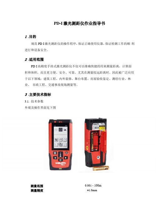
3.主要技术指标3.1.技术参数外观及操作界面见下图0.001 - 100m测量范围测量精度±1.0mm3.2.性能特点4.操作规程4.1.主要功能键4.1.1开关机启动:短暂按启动键。
在按动下个按键前,电池的显示会一直显示在显示屏上的。
关闭:按住关闭键直到仪器关闭。
为了延长电池的使用寿命,在3分钟内未触摸任何键盘时,激光将会自动关闭。
6分钟后仪器将会自动关闭。
4.1.2清除键使用清除键回到上一指令。
在测量面积或体积时,可以用清除键清除单个测量结果,重新进行测量。
4.1.3照明按住照明键,显示屏上的照明会开启或关闭。
在关闭仪器时,灯也会关闭。
4.1.4测量基准边在固定挡板打开时,仪器能自动识别测量基准边,并设置测量基准边以使得到正确的测量值。
测量基准边的标准设置是后沿。
按测量基准边键,可将测量基准边一次性地设置为从这个边出发的测量。
在测量后测量基准边会自动还原为以后沿为基准的设置。
也可以将测量基准边常设为前沿,较长时间按测量基准边-键{A,8}来完成此设置。
较长时间按测量基准边-键{A,8},将测量基准边返回到后沿。
4.2.测量4.2.1单个距离测量按DIST键开启激光。
再按此键进行测量。
测量结果将显示在显示屏上。
4.2.2最大/最小值测量这个功能可以提供从某一点出发来进行的最大或最小值的测量。
用于确定到墙角的距离(最大值)或垂直距离(最小值)等用法。
按住DIST键,直到听到峰鸣声。
缓慢地在目标周围大范围的移动激光,例如:房间的一角。
OPTIBAR操作手册

如果用户通过菜单 ZP 来改变设置从 0 到 20,通过菜 单 EP 来设置从 400 到 300,模拟信号会出现以下改变:
20 bar = 4.00 mA 160 bar = 12.00 mA 300 bar = 20 mA
3.6 压力接口为乳制品管连接的安装步骤 - 检查确保 O 形密封圈的大小适合密封槽的大小。 - 把乳制品管置于对应连接的中心。 - 把卡环旋入对应的接口螺纹。 - 然后用钩形扳手拧紧。
3.7 压力接口为卡箍或 Varivent连接的安装步骤 - 根据测量的介质和输入压力的大小选用适合的密封配 件。 - 把密封件放入对应连接的安装部位。 - 把卡箍连接置于带密封装置的中心位置。 - 然后按照供应商的操作指南选用配套的卡箍(例如半 环卡箍或收拉环卡箍)加固连接。
- 在安装设备的过程中,一定要满足相关的防爆规 定。一定要注意确认该型号(氧气应用)的设备 是否必须要求提供 ATEX 认证。 (交货的标准设 备无 ATEX 认证)
- 注意确认整套测量设备系统的设计必须符合 BAM 标准(DIN 19247)
- 对于额定量程不超过 50bar 的氧气应用设备,要 求采用带 BAM 认证的 V747-75 O 型密封圈。测 量极限值为 40 bar/130°C 和 50 bar/100°C。
开点延迟设置 S4 菜单 25:d4on
关点延迟设置 S4 菜单 26:d4off 最大压力显示 菜单 27:HIPr 最小压力显示 菜单 28:LoPr 测量值更新 (显示更新) 菜单 29:dLdS 模拟节点 S1 菜单 30:tES1
模拟节点 S2 菜单 31:Tes2
7000操作手册

7000 SDS基本操作简介关于这一章:这一章提供了7000 SDS软件的基本操作过程,可以帮助你熟悉ABI PRISM® 7000 序列检测系统(Sequence Detection System)软件。
本章包括以下内容:操作流程图 (2)关于样品板文档 (3)建立样品板文档 (3)设置样品板文档 (5)打开已有的样品板文档 (15)关于检测器的其它方面 (15)查看运行结果 (16)从解链页面查看数据 (23)报告页面 (27)操作流程图关于样品板文档样品板文档是一个包含样品类型、所用引物/探针以及样品在96孔反应板上的位置等有关信息的电子文档。
在运行PCR反应前,必须先建立样品板文档。
你可以用以下三种方式打开一个样品板文档:●建立一个新的样品板文档●打开一个样品板文档模板●打开一个已有的样品板文档在本章中,你将了解到:●样品板文档的作用●如何设置一个样品板文档●运行的结果●如何分析结果建立样品板文档建立一个新的样品板文档:⑴双击电脑桌面上的7000图标。
⑵从文件菜单选择新建,打开一个新文件。
⑶在新文件窗口中,在测定、容器和模板菜单中做相应选择,然后点击OK。
设置样品板文档●建立检测器●通过检测器管理程序将detectors添加到样品板文档。
●通过反应管检查程序将detectors添加到反应管。
●选择样品类型。
●修改样品类型。
●设置标准品(如需要)。
设置染料管理程序:染料管理程序包含一系列与扩增体系相关的染料,能够管理染料的添加和删除。
注意:染料管理程序中添加的新染料,在应用于文件前,都必须经过校准和分析。
校准纯染料的相关信息,参阅单波谱测定。
应用检测器管理程序:检测器是样品板设置中与样本相关的标记。
在Detector Manager里,可以应用已校准过的染料创建detectors,并将其添加到样品板文档中。
应用反应管检查程序:当反应管检查程序设置完后,接着就设置样品板文档。
保存样品板文档为模板:样品板文档设置完成后,能保存为模板,在今后运行仪器时可以直接调用。
乾亨仪器操作说明
镍
4.8—7.2
0.4
六价铬
1.3—2.2
1.6
昆山乾亨
总镍:
校正液:0.4mg/l
吸光度:220秒995秒1995秒(最后一个吸光度值大约为800mE,如果偏低,说明标液低)
六价铬:
校正液:1.6mg/l
吸光度:85秒185秒390秒(最后一个吸光度与前一个吸光度大约相差50mE)
布朗+卢比仪器简易操作
系统时间:system-data or time or yers
测量:menu-service-status-stop-measuring
停止:menu-service-starus-stop
校正:menu-service-status-stop-calibration
测量时间间隔:Menu-Application-seq.prag-Meas prog-MP1-cycle time(以秒计算)
公式参数:Menu-parameter-密码-meas.point-MP NO-MP1-offset-P1
斜率:Menu-Application-calibration-factors-factor3(factor1 factor2 factor3代表斜率1、2、3)
手动采水:选择P1(P代表蠕动泵、P1一般为采样泵)、V1、V8(V1水样进样阀。V7蒸馏水和校正液阀。V8排液阀。V9消解室阀)
低温罐(LNGLPG丙乙烯液氨)的操作手册

天盛油气公司LPG操作手册目录1.LPG罐区机泵使用管理规程2.正常停电换电规程3.空压机操作程序4.氮气发生器操作程序5.变压吸附制氮系统操作程序6.液化石油气筒袋泵操作程序7.BOG压缩机C-101A/B/C操作程序8.采样操作程序9.加臭操作规程-6101A\B、6102操作规程-6101A/B、6102拆管作业程序12.特种设备维护保养制度13.液化石油气泵检修规程14.BOG压缩机检修规程15.BOG压缩机检修后投用规程16.液化石油气汽槽装车程序17.液化石油气火槽装车程序18.海上压力船装货程序19.海上压力船装货程序20.压力船C3、C4混合物卸货程序21.低温船卸货程序LPG罐区机泵使用管理规程为使LPG罐区机泵长周期、稳定、安全运转,特制定以下切换及盘车规定:1.海水泵 P-701A/B/C:A)海水泵每 12小时切换一次,即各班接班后切换在用海水泵,以防电器设备过热产生泵偷停现象.切换泵时要有人在现场监视泵启动情况;B)填写好机泵运行表格,保证各台海水泵至少每周运转 12小时以上;C)每月各台海水泵运行总时间保持基本平衡。
2.消防海水泵 P-702A/B/C:每15天消防海水泵试运一次.泵出口排空到海里,流量控制在900M3/小时,每次运行30分钟。
3.补压泵 P-431A/B,每周五切换一次。
4.货泵 P-101A/B,P-102A/B,P-103A/B,P-104A/B,P-105A/B,P-107,P-108:填写好运行记录,保持每周各泵运行时间基本相同。
5. BOG 压缩机C-101A/B/C:均衡使用,保持每台压缩机总运转时间基本相同,连续运转不超过24小时。
正常停电换电规程1.先通知办公楼人员,装车台及码头停止装车装船;2.停BOG压缩机,出货泵和加臭泵;3.停海水泵和加氯泵;4.停氮气发生器,空压机,关去干燥器的送风阀;5.停消防保压水泵;6.所有运转设备停止后,通知电工停电换电;7.换电结束后,先开消防保压水泵,海水泵;8.开空压机,开冷冻干燥器,五分钟左右干燥器正常后,开送风阀,然后开氮气发生器;9.等氮气发生器运转平稳后,再陆续启动其它设备。
差压变送器操作说明书

简明操作指南Deltabar SPMD70, PMD75, FMD76, FMD77, FMD78差压测量本文档为《简明操作指南》。
详细信息请参考随箱CD光盘中的《操作手册》和其他文档资料。
《简明操作指南》不得替代随箱包装中的《操作手册》。
整套设备文档包括:•《简明操作指南》•CD光盘,内含《操作手册》KA01018P/00/ZH/14.1371218527目录Deltabar S PMD70, PMD75, FMD76, FMD77, FMD78 4...20 mA HART2Endress+Hauser目录1 安全指南 . . . . . . . . . . . . . . . . . . . . . . . . . . . . . . . . . . . . . . . . . . . . . . . . . . . . . . 31.1 指定用途 . . . . . . . . . . . . . . . . . . . . . . . . . . . . . . . . . . . . . . . . . . . . . . . . . . . . . . . . . . . . . . . . . . . . . . . . . . . . . . 31.2 安装、调试和操作 . . . . . . . . . . . . . . . . . . . . . . . . . . . . . . . . . . . . . . . . . . . . . . . . . . . . . . . . . . . . . . . . . . . . . . 31.3 操作安全和过程安全 . . . . . . . . . . . . . . . . . . . . . . . . . . . . . . . . . . . . . . . . . . . . . . . . . . . . . . . . . . . . . . . . . . . . 31.4 返回 . . . . . . . . . . . . . . . . . . . . . . . . . . . . . . . . . . . . . . . . . . . . . . . . . . . . . . . . . . . . . . . . . . . . . . . . . . . . . . . . . . 41.5安全图标 . . . . . . . . . . . . . . . . . . . . . . . . . . . . . . . . . . . . . . . . . . . . . . . . . . . . . . . . . . . . . . . . . . . . . . . . . . . . . . 42 安装 . . . . . . . . . . . . . . . . . . . . . . . . . . . . . . . . . . . . . . . . . . . . . . . . . . . . . . . . . . 42.1 常规安装指南 . . . . . . . . . . . . . . . . . . . . . . . . . . . . . . . . . . . . . . . . . . . . . . . . . . . . . . . . . . . . . . . . . . . . . . . . . . 42.2 安装位置 . . . . . . . . . . . . . . . . . . . . . . . . . . . . . . . . . . . . . . . . . . . . . . . . . . . . . . . . . . . . . . . . . . . . . . . . . . . . . . 52.3 带隔膜密封系统的仪表的安装指南- FMD78 . . . . . . . . . . . . . . . . . . . . . . . . . . . . . . . . . . . . . . . . . . . . . . . . . 62.4组装和安装“分离型外壳”型仪表 . . . . . . . . . . . . . . . . . . . . . . . . . . . . . . . . . . . . . . . . . . . . . . . . . . . . . . . . . 83 接线 . . . . . . . . . . . . . . . . . . . . . . . . . . . . . . . . . . . . . . . . . . . . . . . . . . . . . . . . . . 93.1 连接设备 . . . . . . . . . . . . . . . . . . . . . . . . . . . . . . . . . . . . . . . . . . . . . . . . . . . . . . . . . . . . . . . . . . . . . . . . . . . . . . 93.2 连接测量单元 . . . . . . . . . . . . . . . . . . . . . . . . . . . . . . . . . . . . . . . . . . . . . . . . . . . . . . . . . . . . . . . . . . . . . . . . . 104 操作 . . . . . . . . . . . . . . . . . . . . . . . . . . . . . . . . . . . . . . . . . . . . . . . . . . . . . . . . . 124.1 现场显示单元(可选) . . . . . . . . . . . . . . . . . . . . . . . . . . . . . . . . . . . . . . . . . . . . . . . . . . . . . . . . . . . . . . . . . . 124.2 操作单元 . . . . . . . . . . . . . . . . . . . . . . . . . . . . . . . . . . . . . . . . . . . . . . . . . . . . . . . . . . . . . . . . . . . . . . . . . . . . . 144.3 通过现场显示单元进行现场操作 . . . . . . . . . . . . . . . . . . . . . . . . . . . . . . . . . . . . . . . . . . . . . . . . . . . . . . . . . 174.4锁定/解锁操作 . . . . . . . . . . . . . . . . . . . . . . . . . . . . . . . . . . . . . . . . . . . . . . . . . . . . . . . . . . . . . . . . . . . . . . . 215 调试 . . . . . . . . . . . . . . . . . . . . . . . . . . . . . . . . . . . . . . . . . . . . . . . . . . . . . . . . . 225.1 位置调整 . . . . . . . . . . . . . . . . . . . . . . . . . . . . . . . . . . . . . . . . . . . . . . . . . . . . . . . . . . . . . . . . . . . . . . . . . . . . . 235.2 差压测量 . . . . . . . . . . . . . . . . . . . . . . . . . . . . . . . . . . . . . . . . . . . . . . . . . . . . . . . . . . . . . . . . . . . . . . . . . . . . . 245.3 液位测量 . . . . . . . . . . . . . . . . . . . . . . . . . . . . . . . . . . . . . . . . . . . . . . . . . . . . . . . . . . . . . . . . . . . . . . . . . . . . . 265.4流量测量 . . . . . . . . . . . . . . . . . . . . . . . . . . . . . . . . . . . . . . . . . . . . . . . . . . . . . . . . . . . . . . . . . . . . . . . . . . . . . 29Deltabar S PMD70, PMD75, FMD76, FMD77, FMD78 4...20 mA HART安全指南1安全指南1.1指定用途Deltabar S是差压变送器,用于差压、液位和流量测量。
浙大中控ECS700数字信号输入DI716-S使用手册

DNA测序试剂盒中文操作手册-1

DNA测序试剂盒中文操作手册 BigDye Terminator v3.1和v1.1BigDye Terminator试剂盒简称BDT。
BDT v3.1是DNA测序的标准试剂盒,而BDT v1.1则是专门为PCR 产物测序而优化设计的。
BDT v3.1适用于所有类型DNA模板的测序,对于长片段测序更具优势。
dGTP-BigDye Terminator试剂盒简称BDG。
BDT是DNA测序的标准试剂盒,而BDG则是专门为困难模板测序而优化设计的。
长的重复序列、二级结构、富含GC的片段等通常会干扰测序PCR反应,导致测序失败的DNA模板称为困难模板。
只有BDT v1.0、v2.0和v3.0有相应的BDG试剂盒,BDT v1.1和v3.1本身已有足够能力对付困难模板,所以没有相应的BDG试剂盒。
BDT v1.0、v1.1、v2.0以及BDG v1.0、v2.0可以使用同样的matrix或者光谱校正;BDT v3.0、v3.1以及BDG v3.0可以使用同样的matrix或者光谱校正。
Matrix与光谱校正是同义词。
在不同型号的仪器上,测序的Dye Set选择如下:BDT v3.1 BDT v1.1310/377 E E3100/3100-Avant Z E3700 v2.0 H E3700 v1.1和v1.1.1 D E注意:少数早期的3100和3100-Avant软件中没有MtxStd{Sequencing-SetZ}.par文件,这时可以用MtxStd{Sequencing-SetE}.par代替,用于做BDT3.1的光谱校正。
以下操作适用于BDT v1.1和BDT v3.1试剂盒,而且对于这两种试剂盒的操作完全一样,但是不适用于BDT v1.0、v2.0和v3.0以及 BDG v1.0、v2.0和v3.0试剂盒。
1. 测序DNA模板的纯度与用量DNA纯度:OD260 / OD280 = 1.6 ~ 2.0。
ut(精品)

UT71A/B/C/D/E使用说明书序言尊敬的用户:您好!感谢您选购全新的优利德仪表,为了正确使用本仪表,请您在本仪表使用之前仔细阅读本说明书全文,特别有关“安全注意事项”的部分。
如果您已经阅读完本说明书全文,建议您将此说明书进行妥善的保管,与仪表一同放置或者放在您随时可以查阅的地方,以便在将来的使用过程中进行查阅。
1一、概述二、UT71系列功能对照表三、开箱检查四、安全工作准则五、国际电气符号六、综合指标七、外形结构图八、旋钮开关及按键功能九、LCD显示器十、测量操作说明 1.交直流电压测量 2.交直流电流测量 3.电阻测量 4.电路通断测量 5.二极管测量 6.电容测量7.频率/占空比测量 8.温度测量9.(4~20mA)%测量33445678911111213151617192021目录项目 页2 10.功率测量11.电源档位12.自动关机功能13.按键功能定义十一、技术指标1.直流电压测量2.交流电压测量3.直流电流测量4.交流电流测量5.电阻测量6.电容测量7.频率测量8.二极管测量9.电路通断测量10.温度测量摄氏温度华氏温度11.(4~20mA)% 测量12.功率测量十二、保养和维修1.一般的保养和维修2.更换保险丝管3.更换电池2122222330303133343536373838393939404041414142项目 页3一、概述UT71系列产品具有全功能模拟条图显示,全量程过载保护和独特的外观设计,使之成为性能更为优越的高精度电工测量仪表。
型号UT71A/B是20000计数4 1/2数位,自动量程真有效值数字万用表。
型号UT71C/D/E是40000计数4 3/4数位,自动量程真有效值数字万用表。
本系列仪表可用于测量:真有效值交流或(AC+DC)电压和电流、直流电压和电流、电阻、二极管、电路通断、电容、频率、占空比、温度、(4~20mA)%、有功功率、功率因数、视在功率、最大/最小值、相对测量等参数。
索拉 慧迪恒压变压器操作及维护手册说明书
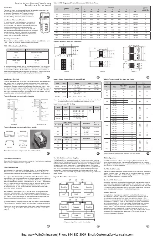
IntroductionThis operating and service manual has been prepared to ensure that your Sola/Hevi-Duty Constant Voltage Transformer can be operated and serviced with minimal effort and involvement. This manual covers Sola/Hevi-Duty Constant Voltage Sinusoidal (CVS) Transformers.Installation - Mechanical PositionAll stock sizes with end housings are intended to be mounted with the silk-screened this side up legend facing upwards. This will place the ventilated capacitor compartment downward, thus providing cooleroperation of the capacitor(s). However, all units will give satisfactory performance if mounted in a horizontal position. In either case, the unit should be mounted in an area where it is unlikely that anyone will come into contact with the core surface of the unit.Mounting ConsiderationsIf a unit is to be wall mounted, the mounting hardware should be sized as in Table 1 below. All mounting holes provided must be used .Table 1: Mounting Screw/Bolt SizingFigure 1: Mounting Holes and DimensionsInstallation – ElectricalOn 60VA or smaller units, screw-type lugs in the outlet box are marked “input” and “output”, and no connection diagram is necessary. Units rated 120 to 15000 VA are provided with multiple inputs for any one, two, three, or four different line voltages, and some have provision for three-wire output. With all units, a connection diagram is attached to the inside lid of the box cover, or inserted in the outlet box. Figure 2 shows typical connections for –8 models, and Figure 3 shows multiple input connections for all other models. Figure 4 shows the output connections for all models.Figure 2: Electrical Connections for -8 modelsInput & Output Connections – All except 250 VAInput Connections - 250 VA Only*Note: The entire load up to the rated capacity of the unit can be drawn from either half of the 240 volt winding. It is not necessary to divide or balance the load.Table 3: Recommended Wire Sizes and Fusing* Leads in the wiring department must be sleeved with 105o C sleeving.Figure 4. Three Phase ConnectionsA: Isolated, Single Phase LoadsB: Separate, Single Phase Loads in Grounded WyeMultiple OperationTwo CVS transformers with the same rating may be connected with their inputs and outputs in parallel. The regulating action will usually be excellent although the standard ±1% cannot be guaranteed. Series connection of either input or output is not e W ith Rectifier LoadsThe ratio of crest to rms values is approximately 1.3 at rated load, and slightly lower at fractional loads. This factor must be considered when all or a portion of the voltage is rectified. The rectified voltage will now be 10 – 15% lower than if connected directly to a sinewave source.Operation W ith Motor LoadsBecause of the current limiting effect described later, special attention should be given to motor applications. In general, the CVS must have a load rating nearly equal to the maximum power drawn during the starting cycle. This may run from two to eight times the normal running rating of the motor. In doubtful cases, it is advisable to measure the actual starting current.Cascade OperationFor applications requiring close regulation, two CVS transformers may be operated in “cascade”. The output of the combination will show little or no detectable change arising from supply line variations of up to ±15%. However, the combined units will still be frequency sensitive (as discussed under Effect of Frequency, page 15). Since even good power systems may vary in frequency by 0.1% or more, the output of a Sola/Hevi-Duty cascade combination may vary by up to 0.25% from this cause alone. In actual practice, then, a cascade combination is highly recommended for special applications requiring regulation in the general region of ±0.25%. If thetandem setup is to be operated at near full rating, then the Type CVS “driver” unit should be one standard size larger than the driven unit, in order to overcome the losses in the latter.Outline A Outline BOutline CAll Except 250 VA250 VA only Constant Voltage Sinusoidal TransformersOperating and Service ManualFigure 3: Electrical Connections for Non-8 modelsNote:Secondaries are not grounded. Ground X2 per Code.All ratings depend on natural draft air circulation for cooling. They should not be mounted in con fined or enclosed spaces unless special provisions have been made for ventilation. Technical Services is available for assistance in doubtful situations (see note on Operating Temperature). Table 2 and Figure 1 show model number with their weight and physical dimensions .Table 2:CVS Weights and Physical Dimensions, 60 Hz Single PhaseThree-Phase Power WiringIf operation from a three-phase source is required, three hardwired regulators may be wired in delta as shown in Figure 4.Other ConsiderationsIt is desirable to have a switch in the input circuitry for turning off power to the unit when it is not in use. While all CVS transformers are designed for continuous duty, they draw appreciable current regardless of output loading. The outputs of all Sola/Hevi-Duty standard CVS transformers are isolated from the input lines. Voltage generated by internal leakage currents will occur with respect to ground. This can have undesirable effects in many pieces of electronic equipment. Therefore, if Figure 4 circuit “B” is used, it is suggested that the installer remove X2 grounding on –8 units, then connect all X2 from each phase to one location and ground at that location only. This is not required for circuit “A”. This will not affect regulation or the ability to reject power line noise or transients.Any three stock units having a tap for 190-260 input connections may be connected in delta to a 240-volt, three-phase power supply. Those units equipped with primary tap for 175-235 volts may also be connected in delta to a 208-volt supply. (Terminals to be used are identi fied on the connection diagram located on the inside face of the outlet box cover.)All stock production, harmonic-free units now have uniform terminal polarity. This eliminates the need for “phasing out” either input or output connections.Output must serve three, independent, single-phase loads of the same total volt-ampere rating. Connections should be made in one of two ways shown in Figure 4.Use With Switchmode Power SuppliesIf a CVS transformer is used as a source for a switchmode power supply, a slight amount of ringing may be noticed on the sinewave output of the CVS at half cycle intervals for a short duration. This ringing occurs at the point when the switchmode power supply current demand drops to zero. The ringing should not be a cause for concern since it is of relatively low magnitude and frequency. The CVS has been tested with a variety of switchmode power supplies and it has been determined that the ringing never affects the Doutputs, nor has it been found to degrade the components of any switchmodepower supply.Physical Characteristics of Operation Operating TemperatureStandard units are designed to operate in ambient temperatures of minus 20°C to plus 50°C. In operation, a temperature rise will occur whether or not the transformer is serving load. Normally, this rise may fall anywhere in the range of 45°C to 110°C, depending on the type and rating. In any case, the maximum operating temperature at an ambient of 50°C is always within safe operating limits for the class of insulating material used. (Special units can be designed for lower heat rise or wider ambient temperature range.)External Magnetic FieldsIn almost all applications, this effect may be disregarded. On critical applications, care should be exercised in the orientation of the core with respect to critical circuits, in order to minimize the effect of the field.In certain rare cases in which the transformer is connected to, or mounted near, high gain audio frequency circuits, special attention may need to be given to adequate physical spacing and/or orientation of the CVS transformer to avoid interaction with the audio circuits. Sola/Hevi-Duty’s Technical Service Department (800-377-4384) may be able to offer suggestions for such problems.Electrical Characteristics of Operation Checking With VoltmetersAll checks on output voltages should be made with a true RMS voltmetersuch as a Fluke model 8020 A. Rectifier-type voltmeters will not give accurate readings due to the small amount of harmonics present in CVS output.Load RegulationChanges in output voltage resulting from changes in resistive loads areusually small - running one percent or less in the larger units. Table 4 shows average values for output voltages.Table 4: O utput Voltage Changes – 20% Load to Full Load(100% Power Factor – Nominal Input Voltage)Factors Affecting OperationInput CharacteristicsAs the Sola/Hevi-Duty CVS transformer includes a resonant circuit that is fully energized whether or not a load is present, the input current at no load or light loads may run 50% or more of the full-load primary current. As a result, the temperature of the unit may rise to near full-load levels, even at light or nonexistent loads. Input power factor will average 90-100% at full load, but may drop to approximately 75% at half load and 25% at no load. In any case, it is always leading.Effect of Load Power FactorThe median value of output voltage will vary from the nameplate rating of the load if a power factor other than that for which the unit was designed is used. Load regulation will also be relatively greater as the inductive load power factor is decreased (see Figure 5). However, the resulting median values of the output voltage will be regulated against supply line changes at any reasonable load or power factor.Figure 5: Median Output Voltage vs. Load Power FactorChange in “Median” Output Voltage vs. Load Power Factor at various loadsEffect of FrequencyChanges in the frequency of the supply voltage will be directly reflected in the output voltage. A change of approximately 1.8% in the output voltage will occur for every 1% change in input frequency in the same direction as the frequency change.Effect of TemperatureThe output voltage will show a small change as the unit warms up to stable operating temperatures at a constant ambient temperature. This change may be about 1 or 2% depending on the unit’s VA rating. At a stable operating temperature, the output voltage will change slightly with varying ambient temperature. This shift is approximately 1% for each 40°C of temperature change.Current LimitationWhen the load is increased beyond the transformer’s rated value, a point is reached where the output voltage suddenly collapses and will not regain its normal value until the load is at least partially released. Under a direct short circuit, the load current is limited to approximately 150-200% of the rated full load value and the input wattage to less than 10% of normal. A CVS will protect both itself and its load against damage from excessive fault currents. Fusing of load circuits is not necessary.Manufacturing ToleranceThe nominal output voltage of each stock Constant Voltage Transformer is adjusted at the factory to within plus 2%, minus 0% of rated (nameplate) value with rated, nominal voltage at rated frequency applied to the input, and with full rated load at 100% power factor applied to the output. This adjustment is made with the unit at substantially the same temperature as room ambient temperature (25°C).ServicingRoutine MaintenanceAs the Sola/Hevi-Duty CV Transformer is a simple rugged device without moving parts or manual adjustments, no servicing or maintenance is needed in the ordinary sense. The percentage of possible poor performance or failure is exceedingly low. In any case of apparent poor performance, the user is urged to check the following points immediately:Checklist on Factors Affecting Performance A. Nominal Voltage Too High1.The load may be considerable less than full rating. (See “Load Regulation”).2.The load may have a leading power factor.B. Nominal Voltage Too Low1.Load power factor may be lagging. (See Load Regulation).2.Unit may be slightly overloaded. (See Current Limitation).C. Does Not Regulate Closely1.Unit may be slightly overloaded. (See Current Limitation).2.Actual line voltage swings may be outside the rated coverage of unit, particularly on the low side.3.On varying loads, a certain amount of load regulation may be mixed with the line voltage regulating action. (See Load Regulation).D. Output Voltage Very Low (20-60V)1.Unsuspected or unplanned overloads of substantial size may occur intermittently (motor-starting currents, solenoid inrush currents, etc.). (See Current Limitation).2.One or more capacitor units in the CVS transformer may be defective. (See Field Replacement of Capacitors)Checklist on Factors Affecting Performance - continued E. No Output Voltage At All1.Check power source breakers or fuses.2.Check continuity between input terminals, and also between output terminals.G. Transformer Operating Temperature1.These transformers are designed to operate at high flux density, and hence, relatively high temperatures (see OperatingTemperature). After connection to line for a half hour or so, the exposed core structure may be too hot to touch with bare hand, but this is normal and need give no concern. However, if there is any indication of oil or compound leakage, unit should be returned to factory (see below).NoteIn case the transformer is operating but does not appear to have the correct output, it is very helpful to apply the following test:1.Disconnect the working load.2.Connect a dummy load of lamps, heaters, or other resistive load substantially equal to the full load rating of transformers, directly across its output terminals.3.Measure the output voltage of the CVS using a true RMS type voltmeter directly across its output terminals.This test will usually establish whether the apparent poor performance is due to a fault in the CVS transformer or to some peculiarity of the working load. Sola/Hevi-Duty’s Technical Service Department will then be in far better position to give helpful service advice or suggest factory test or service as indicated.Factory Test and InspectionIf the field test suggested earlier indicated that the CVS transformer itself may be faulty , a full report of the difficulty should be communicated to the place of purchase, with a request for permission for return. The Authorized Sola/Hevi-Duty Distributor may then suggest further helpful field tests, or authorize return for inspection at once. A Return Authorization Number will be issued. This number must appear on the outside of the shipping container. Otherwise the shipment will not be accepted.Field Replacement of CapacitorsCapacitors used in all CVS transformers are of the highest commercialgrade available. Nevertheless, there is a certain small percentage of failure. Sola/Hevi-Duty’s guarantee includes free replacement at the factory of any capacitor unit that fails within one year from date of purchase. Older units can be replaced at moderate charge.It may be possible to test and identify defective capacitors in the field, and to make field replacement with new units shipped from the factor y. In all such cases, factory advice and cooperation should be requested in advance.WarrantiesSola/Hevi-Duty warrants its standard catalog products to be free from defects in materials and workmanship and agrees to correct by repair or replacement, at the option of Sola/Hevi-Duty, products that may fail inservice provided the product has been installed, operated and maintained in accordance with accepted industry practice.Warranty begins at the date of manufacture and is according to the following schedule:1.Standard catalog transformer and single phase power conditioning products – 10 years plus an additional 2 years if online registration i s completed within 14 days after installation.2.Products manufactured to a purchaser’s specifications – 1 yea r.Return PolicyMost instances of initial failure to operate properly can be remedied through a telephone conversation between the user and Technical Service. If it isdetermined that a product must be returned, contact your local Sola/Hevi-Duty distributor for a Return Authorization. If the distributor is unknown, contact Customer Service by e-mail at ReturnGoods.All returns to the Sola/Hevi-Duty factory must have a Return Authorization (R.A.#). The following information required for a Return Authorization (R.A.#):1.Sola catalog number and/or model number.2.Serial number.pany name, address, phone number and contact person.4.Proof of purchase from Distributor.5.Description of problem.For proper handling upon receipt at Sola/Hevi-Duty, the R.A.# mustbe clearly placed in several locations on the outside of the package. Sola/Hevi-Duty is not responsible for damage on returned goods not packaged properly or customer-abused units.Constant Voltage Sinusoidal TransformersOperating and Service ManualPhase ShiftThe phase difference that exists between input voltage and output voltage is in the range of about 120° to 140° at full load. This phase difference varies with the magnitude of the load and, to a lesser extent, with changes in line voltage.Output Wave ShapeThe CVS transformers all include harmonic-neutralizing circuitry. These units typically have less than 3% total harmonic distortion at full load and less than 4.5% at no load.Response TimeAn important advantage of the Sola/Hevi-Duty principle of static magnetic regulation is its exceedingly fast response time compared with other types of AC regulators. Transient changes in supply voltage are usually corrected with a Sola/Hevi-Duty CVS with 1 1/2 cycles or less, the output voltage will not fluctuate more than a few percent durin g this interval.IsolationSince the input and output are separated not only electrically, but also physically, by a magnetic shunt, the Sola/Hevi-Duty CVS has a strongerisolating effect than a conventional transformer. This may often eliminate the need for static shields.P/N 299-35206-01Rev. 05 (Nov 2014)。
定氮仪操作规程

定氮仪操作规程
《定氮仪操作规程》
一、仪器准备
1. 将定氮仪放置在通风良好的实验室中,并接通电源。
2. 根据使用要求,准备好所需的实验用品和化学试剂。
3. 检查仪器的各项部件是否完好,如有损坏应及时更换或修理。
二、样品准备
1. 取样品并将其称量至指定的重量。
2. 若需要进行预处理,按照实验要求进行处理,并确保处理过程不会影响定氮仪进行测定。
三、操作步骤
1. 打开定氮仪的软件程序,并进行相关设置。
2. 将样品放入定氮仪的样品舱中,并严格按照仪器操作手册进行操作。
3. 启动定氮仪进行测定,并等待测定结果出来。
四、结果分析
1. 根据测定结果计算出样品中的氮含量。
2. 对结果进行分析和比对,确保测定结果的准确性和可靠性。
五、仪器维护
1. 测定结束后,及时清洁定氮仪各个部件,保持仪器的清洁和整洁。
2. 定期对定氮仪进行维护保养,确保仪器的正常运行。
六、安全注意事项
1. 在操作定氮仪时,应注意避免吸入或接触化学试剂或有毒气体。
2. 操作过程中,严格按照操作规程进行,不得随意更改或忽略步骤。
3. 操作结束后,关闭定氮仪电源,并注意对实验室进行清洁和安全检查。
通过严格按照操作规程进行操作,可以确保定氮仪的准确性和可靠性,同时也能保障实验人员的安全。
在实验操作过程中,还应随时关注仪器的运行状态,及时发现问题并进行处理,以确保实验结果的准确性和可靠性。
TENMA 电焊站操作手册说明书

TMESD Safe Soldering StationUser ManualAT980D EU & AT980D UK TMThank you for purchasing the TENMA Soldering station. Please read this manual before operating the equipment.Keep manual in accessible place for future reference.What’s IncludedControl Unit 1 No.Soldering Iron 1 No.Soldering Iron Holder 1 No.Power Cord (UK or EU) 1 No.Cleaning Sponge 1 No.User ManualSafety Precautions• This product is meant for use by trained and qualified personnel only. Keep away from children• Do not dis-assemble the control unit. There are no user serviceable parts• Do not use the soldering station in the vicinity of flammable material• Use appropriate safety gear and exercise caution while using this soldering station• Do not touch the soldering tip as the temperature can be 200°C to 400°C when in use• User proper power cord• For changing the soldering tip, ensure that the power supply is turned off and allow sufficient time for the tip to cool down.• T he soldering tip should be cleaned by wiping it on the cleaning sponge provided. This will help get rid of the burnt solder or fluxes that cause oxidation on the soldering tip. Not cleaning the tip might lead to improper soldering.•SpecificationsInput Voltage220V AC ±10% 50HzPlug Type UK, EUPower Consumption80W (Max.)Temperature Controlling Range150°C to 450°C (302°F to 842°F)Heater Voltage24V ACTemperature Stability±1°C (Static)Display LCDMax. Surrounding Temperature40° CCalibration Method DigitalTemperature Range for Calibration50°C to -50°C (122°F to -58°F)Ground Impedance< 2ΩGround Voltage< 2mVHeating Element 4 Core*Specifications are subject to change without prior notice. TMHeating elementAT938D/AT980D Control Panel GuideLCD displayFeatures:• New appearance design, big LCD screen, for clear and convenient reading.• PID power control loop with constant temperature set by MCU computer for more precision temperature control.• Imported temperature-beard materials with long life. TM• It is convenient that the device adopt three programmable knobs in different condition.• Display the temperature between Fahrenheit and Celsius flexibly, convenient for the type of operators.• Computerized temperature calibration can correct the difference between the actual and display temperature quickly.• Heating clement malfunction alert.Operating GuidelinesPlease refer to the “Control Panel Guide” section for buttons and display panel details1. Connection:1.1. Insert soldering iron’s plug into the socket and tighten the nut on the plug securely and place it in iron holder.1.2. Inset station’s power cord into power plug on the back panel and plug the cord into a power source.2. Power on:2.1. Turn on the unit.2.2. T he Digital display will initially display the current set temperature (the value of last time using) for 3 seconds. After fewseconds it would display the actual temperature with temp unit “°C or °F”. (diagram 1), (diagram 2)3. Adjusting temperatureUnder normal working condition, pressing and holding button “▲” or “▼”, you can either increase or decrease the temperature quickly. Keeping the knob in pressed will adjust the temperature setting quickly; short pressing knob, you can adjust temp stepby step. The display screen shows the temperature value simultaneously. Release knob for 3s to store. (Diagram 3)4. Quickly adjusting temperature4.1. U nder working condition, you can set working temperature quickly by programmable buttons. Press the button once toextract setting temperature stored in button”1, 2 & 3”, this way you can easily set the working temperature. TM4.2. Pressing button “#” and buttons “1, 2, 3”, you can store the setting temperature into fast channel knobs “1, 2, 3”.4.3. Temperature hotkeyA. Hotkey 1 is usually applied to store a 200°C or lower temperature value at which level machine stands by and on rest.B. Hotkey 2 is a shortcut of temperature between 300°C to 350°C at which level a general soldering job can be done.C. Hotkey 3 is a fast channel to high temperature of 380°C specified for special welding job.5. Temperature calibrationYou need calibrate the temperature of tip after you replace with a new heating element or tip.5.1. Enter into calibrating station by long pressing knob “*” (>3s).5.2. You can directly adjust the value of calibration by pressing knob “▲” or “▼”.5.3. T he value of calibration is temperature measured minus the settings.(e.g. Actual value 380°C - setting value350°C = +30°C. Pressing knob “▲” adds 30°C; Actual value 320°C - setting value 350°C = -30°C.Pressing knob “▼” minus 30°C).5.4. The calibrating temp range is +50°C ~ -50 °C.5.5. You can press knob “*” to store after you finish calibration. (diagram 4)6. Temperature unit exchangeI n the power off condition, press and hold knob”#”, then turn on the station, the temp unit will be changed between “°C” and“°F” and store automatically.7. Temperature lock function (AT980D only)T emperature LockDisplay:”Loc”, short of Lock, located in right bottom of LCD display screen. Temperature lock & unlock func-tion can be realized by pressing “#” for three second or longer. Whenever the machine is locked as above photo shows, the functional key in panel lose effect. TM8. False alarmWhen “H-E” or “S-E”is displayed on the screen, there is some wrong in heating element or the circuit. (diagram 5, 6). Turn offthe unit and follow the instructions to replace the heating element.Replacing the heating elementNote: diagram (8) is soldering station AT980D, heating core resistance (red) about 2.5 ~ 3.5Ω, sensor (blue)resistance about 43 ~ 58Ω.1. Power off the unit and unplug the device. Wait for the heating element to cool down.2. Loosen the nut (1)3. Remove the tip retainer (2) and soldering tip (3)4. Unscrew heating contact (4), remove grouping spring (5)5. Remove the full heat wire group (6).6. Please reference to diagram Section (7) - (8)7. Replace the old one the good condition heating element8. Reverse the process to secure the heating element in the handle.Care and Maintenance• Keep the soldering station dry; if it gets wet, dry it immediately.• Use the soldering station only in normal temperature environments.• Keep the soldering station away from dust and dirt.• T he soldering iron tip should be cleaned after use by wiping it on the damp sponge found in the soldering iron stand. This is to get rid of burnt solder or fluxes that cause oxidation on the tip. TMChanging Soldering Tip• Always turn the power OFF when removing or inserting a tip• Let the tip to cool down to room temperature before holding it with heat resistant pads• Unscrew the metal cap nut (1).• Pull out the shaft of the soldering iron(2).• Replace it with a new soldering tip.• Put back the shaft and securely lock with the metal cap nutCorrect Disposal of this product.9. Soldering Tip Care and Usea. Tip Temperature• High soldering temperatures can degrade the tip• U se the lowest possible soldering temperature. The excellent thermal recovery characteristics ensure efficient and effective soldering even at low temperatures• W hen not in use, do not leave the soldering iron on at a high temperature as the tip’s solder plating will get covered by oxide, reduction it’s heat conductivityb. Cleaning• C lean the tip regularly with a cleaning sponge, as oxides and carbides from the solder and flux can form impurities on the tip. These impurities can result in defective joints or reduce the tip’s heat conductivity• W hen using the soldering iron continuously, be sure to loosen the tip and remove all oxides at least once a week. This helps prevent seizure and reduction of the tip temperature• After use, wipe the tip clean and coat with fresh solder. This helps prevent tip oxidation.10. Changing the Soldering Tipa. Always turn the power OFF when removing or inserting a soldering tipb. Let the tip to cool down to room temperature before holding it with heat resistant padsc. Loosen nut (1 in diagram 7)d. Pull out the shaft of the soldering iron (2 in diagram 7)e. Remove the old soldering tip and replace with new one (3 in diagram 7)f. Reverse the process to secure the soldering tipg. P referred Soldering Tips : 21-10140, 21-10142, 21-10144, 21-10146, 21-10148, 21-10150, 21-10152, 21-10154, 21-10156,21-10158Important Notice : This data sheet and its contents (the “Information”) belong to the members of the Premier Farnell group of companies (the “Group”) or are licensed to it. No licence is granted for the use of it other than for information purposes in connection with the products to which it relates. No licence of any intellectual property rights is granted. The Information is subject to change without notice and replaces all data sheets previously supplied. The Information supplied is believed to be accurate but the Group assumes no responsibility for its accuracy or completeness, any error in or omission from it or for any use made of it. Users of this data sheet should check for themselves the Information and the suitability of the products for their purpose and not make any assumptions based on information included or omitted. Liability for loss or damage resulting from any reliance on the Information or use of it (including liability resulting from negligence or where the Group was aware of the possibility of such loss or damage arising) is excluded. This will not operate to limit or restrict the Group’s liability for death or personal injury resulting from its negligence. Tenma is the registered trademark of the Group. © Premier Farnell Limited 2016.。
液化天然气(LNG)运行操作手册
液化天然气(LNG)气化站运行操作手册上海清泰液化天然气有限公司编制二零零五年八月公司简介上海清泰液化天然气有限公司是一家致力于液化天然气(LNG)事业发展、集投资开发与工程建设于一体的专业化公司,伴随着中国LNG产业发展而成长。
公司汇集一批在LNG产业领域里从事理论研究和工程实践的先行者,围绕LNG资源进口、储运、终端利用和技术研发开拓业务,为促进国家能源结构变革、提高能源综合利用效率、保护生态环境而进行着努力和探索。
上海清泰公司奉行“真诚合作、协调发展”的企业精神,不断追求先进的项目管理模式,努力打造清泰品牌。
清泰公司愿与燃气界同行一起努力,共同推动中国LNG产业发展,为LNG 在中国的广泛普及应用作出积极贡献。
联系方式:上海清泰液化天然气有限公司公司地址:上海浦建路145号强生大厦1602室联系电话:021-********,50899291传真号码:021-********液化天然气(LNG)气化站运行操作手册目录公司简介 0目录 (1)第一章天然气与液化天然气(LNG)知识 (4)2.4。
4 立式低温贮罐运行操作规程2。
4.5 水浴式加热器操作规程 (19)2.4。
6 加臭机操作规程 (20)2。
4.7 燃气锅炉操作规程 (20)2。
4.8 氮气瓶组操作规程 (20)2。
4.9 二氧化氯发生器操作规程 (20)2.4。
10 消防水泵操作规程 (21)2.4。
11 柴油机操作规程 (21)第1 页液化天然气(LNG)气化站运行操作手册2。
5 安全操作注意事项 (22)2.6 设备巡检 (23)2。
7 故障处理 (23)第三章消防 (24)3。
1 消防设施 (24)3.2 消防安全管理 (24)3。
2.1 消防安全管理制度 (24)3。
2.2 灭火救援 (25)7.1.1 来自天然气的危险 (34)7。
1。
2 来自LNG的危险 (34)7。
2 风险控制 (35)7。
2。
1 对可能产生超压的设备管线设置安全泄压系统 (35)7。
加氢纯化制氮装置操作说明书

加氢纯化制氮装置操作说明一、普氮装置开机步骤1.1、开机操作前的准备使用前请认真阅读有关说明书,注意正确使用。
1.2开机1.2.1 开启电控柜的电源开关。
1.2.2 开启净化设备冷冻式干燥机,预冷3~5分钟。
1.2.3 空压机加油到油位线。
1.2.4启动空压机向整机供气。
1.2.5调节调压阀,使仪表气压力在0.4~0.6MPa范围内。
1.2.6待净化空气缓冲罐压力升到0.7MPa,开启操作面板上的普氮启动按钮,控制系统启动,电磁阀按预定程序动作,气动阀也对应动作,制氮装置进入运行状态。
1.2.7缓慢开启制氮装置前调节阀,向制氮装置供气。
1.2.8变压吸附制氮装置刚进入运行状态,普氮纯度还不合格,普氮缓冲罐的普氮不要进行放空,待普氮缓冲罐压力上升到0.7MPa左右,手动打开调节不合格放空闸阀,放空流量控制在流量计面板显示流量90m3左右(普氮流量计要进行换算,面板显示数值约为实际流量值2倍,),待普氮纯度接近合格纯度99%时,调大不合格气放空调节阀,控制流量面板显示150 m3以内,加快不合格氮气放空,普氮纯度合格后,普氮不合格放空气动阀自动关闭,普氮合格气气动阀自动打开。
注:普氮放空转换开关手动闭合(正常状态)时,当普氮纯度不合格时,普氮不合格放空气动阀自动打开,普氮合格气出口气动阀自动关闭。
普氮放空转换开关手动断开时,当普氮纯度不合格时,普氮合格气出口气动阀打开,普氮不合格放空气动阀关闭。
1.2.9普氮纯度达到要求后,待氮气缓冲罐压力升到0.6Mpa时,则准备操作供气。
1.2.10供气时先用调压阀调整好普氮压力为0.55~0.6Mpa(可调),缓慢开启普氮合格气出气调节阀,注意流量计显示,注意保持压力。
1.3运行监测设备在运行过程中,需定时检查各设备运行状况:空压机是否工作正常,冷干机是否工作正常,进气温度是否正常,吸附压力是否正常,阀门动作时序是否正常,普氮纯度、压力、流量是否正常。
1.4注意定时排放冷干机、高效油水分离器、精密过滤器、活性碳过滤器内的污水杂质,每班至少排放5~8次,定时检查自动排水器工作是否正常。
- 1、下载文档前请自行甄别文档内容的完整性,平台不提供额外的编辑、内容补充、找答案等附加服务。
- 2、"仅部分预览"的文档,不可在线预览部分如存在完整性等问题,可反馈申请退款(可完整预览的文档不适用该条件!)。
- 3、如文档侵犯您的权益,请联系客服反馈,我们会尽快为您处理(人工客服工作时间:9:00-18:30)。
PD71 特高频(和高频)便携式局部放电检测仪用户使用手册版本号:1.0目录1. 设备概述 (3)1.1 目的 (3)1.2 设备技术参数表 (4)2. 硬件配置 (5)2.1 PD71设备的外部连接 (5)2.2 PD71设备可支持的典型传感器 (8)2.3 工频信号同步收发器 (10)3. PD71 软件 (11)3.1 软件登陆 (11)3.2 主界面 (12)3.3 数据库管理界面 (14)3.4 设置 (16)3.5 局放数据显示界面 (20)3.6 数据采集和处理 (28)3.7 显示设置 (33)3.8 USB连接及电源频率显示 (34)4联系方式 (34)PD71便携式特高频局部放电检测诊断仪3 / 341. 设备概述 1.1 目的PD71设备是一款功能非常全面的便携式特高频局部放电带电检测装置,可以用于测量高压设备中辐射的特高频(含高频)电磁脉冲信号,用于分析高压设备的绝缘状态。
它紧凑、轻巧、便于携带,能够简洁地显示数据和分析信息,广泛适用于电力变压器、套管、GIS 、电缆等各种高压设备。
PD71设备还可以捕获并存储绝缘中的局部放电脉冲波形,进而采用专家数据库对其进行分析和诊断。
该设备在支持特高频传感器的同时,还支持RFCT 、TEV (暂态地电波)传感器。
通常情况下,在使用特高频传感器进行电力变压器、GIS 等设备的绝缘状态时,建议采用特高频传感器的时候,还可以采用RFCT 和TEV 传感器(宽频传感器均可)进行对比,但建议采用SDMT 公司生产的传感器,以确保最高的灵敏度和最可靠的性能。
紧凑的设计可以更容易的携带,一般在几分钟内即可部署完并开始测试,笔记本电脑已经集成于设备箱内。
一旦部署完,点击开始后,设备即开始进行测试,并会输出PRPD 图谱、3D图PD71便携式特高频局部放电检测诊断仪4 / 34谱、PD-cloud 图谱和趋势图谱。
1.2 设备技术参数表PD71设备的技术参数如表1.1。
描述 参数局放通道 6 支持的传感器 特高频传感器、高频传感器和暂态地电压传感器支持的特高频频带 200 - 1500 MHz 支持的高频频带0.5 – 20 MHz特高频灵敏度 -10 to -70 dBm高频灵敏度 -10 to -70 dBm 数据显示相位分辨率 1 - 7.5 度 通道之间的时间精度 约 1ns 最大的脉冲率 1,000,000/秒工频同步输入内同步和无线同步工作电压 ~220 V 工作温度-20 - +55 °C保质期 12 个月 使用寿命大于5年设备尺寸 260х250х80mm设备重量 8.0 kg.表1.1 技术参数表设备采用独特的局部放电脉冲算法,能从非常复杂的噪声中提取局部放电信号,还可选用PDScrypt 算法,可进一步对局部放电类型进行分析和诊断。
使用PDScrypt 算法来分析和识别PD 局放脉冲,适用于不同类型的高压设备,如GIS 、变压器、发电机、电缆、开关柜、断路器等。
先进的基于局放波形和时间的噪声过滤算法,可自动的滤除外部干扰噪声信号。
同时,PD-cloud 功能还可以分离单个通道中的多个局部放电源。
PD71便携式特高频局部放电检测诊断仪5 / 342. 硬件配置2.1 PD71设备的外部连接PD71所有的连接均位于面板表面,如图2.1。
图2.1 PD71设备外部连接图PD71设备的6个输入通道PD1~PD6,如图2.2。
图2.2 PD71设备输入通道PD71便携式特高频局部放电检测诊断仪6 / 34PD71设备的USB 连接端口,如图2.3。
图2.3 PD71设备的USB 连接端口PD71设备的电源输入端口、熔丝、电源开关和接地点,如图2.4。
图2.4 PD71设备的电源接口及接地点PD71便携式特高频局部放电检测诊断仪7 / 34PD71设备采用的过流保护为2A ,20mm 型。
!!!在进行高压设备局部放电测试时,务必请保证设备良好可靠接地。
设备自带一个电源输出接口,可用于笔记本连接或其它附件使用,最大支持的电流为1A 。
图2.5 PD71设备的辅助电源输出点设备自带环境温度、湿度传感器,用于监控和记录环境中的温度和湿度,用于对比不同环境下的测试结果。
图2.6 PD71设备的温湿度传感器PD71便携式特高频局部放电检测诊断仪8 / 342.2 PD71设备可支持的典型传感器 特高频传感器图2.7 不同类型的GIS 外置式特高频传感器图2.8 不同类型的GIS 内置式特高频传感器图2.9 变压器外置式特高频传感器PD71便携式特高频局部放电检测诊断仪9 / 34● 高频传感器图2.10 高频电流传感器● 暂态地电波(TEV )传感器图2.11 TEV 传感器PD71便携式特高频局部放电检测诊断仪10 / 342.3 工频信号同步收发器工频信号同步收发器如图2.12。
该收发器采用无线传输方式,即可采用220V 市电,也可以采用VT 输入进行工频信号同步。
图2.12 工频信号同步收发器该工频信号同步收发器的工作电源既支持220V 市电,也支持电池供电。
该工频信号同步收发器有两种使用模式,即发送模式和接受模式。
但PD71仅使用其发送模式。
在发送模式下,当选择VT 输入或市电输入其中一种输入时,设备即可以自动进行工频同步。
设备本体上存在一个开关和两个LED 指示灯,如果遇红色灯亮,即表示电源正常,如该等一直闪烁,即表示电池电量低。
如果绿色等亮,及表示同步信号已经被检测到并正在通讯。
图2.12 工频信号同步收发器指示灯PD71便携式特高频局部放电检测诊断仪11 / 343. PD71 软件3.1 软件登陆PD71软件支持两种操作模式:● 用户模式:仅支持特高频局放检测,无登陆密码,直接点击即可进入。
● 工程师模式:同时支持高频和特高频检测模式。
软件登陆界面:图3.1 用户登陆模式图3.2 工程师登陆模式在工程师模式中,其登陆密码为op123,支持对相关参数进行设置,一般适用于对局部放电比较熟悉的工程师。
PD71便携式特高频局部放电检测诊断仪12 / 343.2 主界面显示主界面包括三个部分:设置界面、数据存储界面和局部放电信号显示界面。
图3.3软件显示主界面设置界面和数据存储界面可以选择显示或隐藏,如图3.4中的红色方框内的左、右显示条。
图3.4软件界面显示控制条软件设置界面数据存储界面局放显示界面PD71便携式特高频局部放电检测诊断仪13 / 34图3.5设置、数据存储界面展开图 同样,也可以同时隐藏设置界面和数据存储界面。
图3.6设置、数据存储界面关闭图PD71便携式特高频局部放电检测诊断仪14 / 343.3 数据库管理界面进行数据库配置可选择主菜单下的数据库->连接设置,进行设置。
图3.7数据库设置界面强烈建议不修改数据库的连接设置,除非用户知道如何操作,因为不正确的修改可能会导致在PD71关闭后数据不会进行存储。
该数据库可与其他PD71的数据库进行负责和备份。
在修改设置时,请务必与SDMT 工程师连接,确保所有操作正确。
创建数据库后,用户可以很容易的进行相关信息设置,通常情况下,其存储结构为“公司-变电站/电厂-设备具体位置”。
最后一层存储结构为为“添加测试设备”,PD71将会自动会被选择。
图3.8添加测试信息所有的测试数据将存储于设备名称GIS-DM 下。
PD71便携式特高频局部放电检测诊断仪15 / 34图3.9添加测试信息当选中相关存储数据后,右侧会自动显示相关测试数据。
图3.10 选择存储数据后的显示界面PD71便携式特高频局部放电检测诊断仪16 / 343.4 设置在测试过程中,可进行相关参数设置。
图3.11 通道和相位选择PD71有6个测量通道,这些通道可分别进行“打开”或“关闭”, 一般推荐关闭未连接传感器的通道。
每个通道可分别监测高压设备的三相,分别为A 相、B 相、C 相,其相位角一般为0°、 120° 和240°。
同样也存在一些三相共体设备中,其相位可能为AB 、BC 和CA ,相应的相位角为60°、180°和 300°。
在用户模式下,传感器类型固定设置为UHF (特高频);在工程师模式下,传感器类型可在UHF 、HF 和TEV 下进行选择,选择UHF ,即只能检测UHF 信号;选择HF ,即只能检测HF 信号;选择TEV ,即只能检测TEV 信号。
PD71便携式特高频局部放电检测诊断仪17 / 34图3.12传感器类型选择界面在“数据采集”选项中,以确定PD71如何进行信号的采集和处理,<<N>>为工频周期20mS 。
通常我们选择N=50,如修改N 的数值,相应的3D 图谱也会发生变化。
“PD 参数”设置为趋势显示刻度,通常选择Qmax 。
在当前软件版本中,“保存信号形式”是被禁用的。
图3.13 数据采集设置界面PD71便携式特高频局部放电检测诊断仪18 / 34“数据显示”主要用于调整局放图谱的显示刻度。
“刻度”存在两种方式,一种为标准刻度,另外一种为固定刻度。
标准刻度即显示“-70dBm-0dBm ”,固定刻度即可按照设置数值进行显示。
图3.14 数据显示设置界面图3.15 “自动刻度”显示界面PD71便携式特高频局部放电检测诊断仪19 / 34图3.16 “固定刻度”显示界面“参数”设置中,可进行相位分辨率的设置,该设置主要用于PRPD 和3D 图谱显示。
PD 点时间可精确到nS 级,故需要在“3D ”图的相位中显示以用于计数。
以5度对360度进行平均,单个周期大约为64个点。
图3.17 “参数”显示界面PD71便携式特高频局部放电检测诊断仪20 / 34在HF 测试模式下,其幅值一般以“V ”或“nC ”进行显示, UHF 模式下幅值总是显示为dBm 。
“内置参数”中,主要用于设置市电与高压设备的相位角的偏移。
“使用滤波器”,即采用内部规则安装波形和时间的方式进行噪声过滤。
3.5 局放数据显示界面局放数据显示界面中,主要有三个选项卡,分别为PRPD 、3D 和PD-Cloud 三种图谱。
该数据可来自于存储于数据库内的数据、实时采集的通道数据和将存储的数据。
双击显示条,即可全屏显示局放数据显示界面。
PRPD 图谱是查看PD 的标准格式,由相位、幅值组成二维图谱,局放脉冲数和幅值将以不同颜色进行显示。
图3.18 PRPD 图谱显示界面3D 图谱显示了相位、周期数和局放幅值的关系。
如果采集周期为50,那么将显示50个周期1秒的数据。
PD71便携式特高频局部放电检测诊断仪21 / 34脉冲的颜色按幅值进行显示。
图3.19 3D 图谱显示界面在此显示界面中,可按住鼠标右键进行图谱旋转。