石博士石材扫描仪用户手册(中文版)
Calypso4.2 训练手册(基础篇)

扫描式三次元软件操作手册台 湾 仪 器 行第一章操作流程4第二章开始Calypso / 结束Calypso5第三章主窗口介绍 ( 一 )8第四章回到机械坐标原点 ( Homing the CMM )10第五章安装和校正探头 ( Installing and Qualifying Probes )11第六章设定工件坐标系统 ( Defining the Base Alignment )20第七章移动,旋转和删除坐标系统28第八章设定安全平面 ( Setting the Clearance Planes )31第九章量测几何元素 ( Defining Part Features )38第十章几何元素窗口内的功能43第十一章特征的量测路径产生 - Strategy47第十二章特征评定区 ( 量测特征的结果是否公差内之评定 )51第十三章准备区其他功能介绍53第十四章执行CNC程序窗口57第十五章工件重置后 , 再执行CNC程序60第十六章档案 - 基本指令功能62第十七章几何元素的合成元素63第十八章特征计算 -- 尺寸67第十九章计算 -- 形状和位置68第二十章结果输出79第二十一章单位设定84第 二十二 章CAD档的应用85第二十三章工具栏编辑88第二十四章编辑报表表头89第二十五章以 Excel 输出报表92第二十六章重新叫回之前之量测结果97第二十七章曲线之量测 (选配)99第二十八章第 一 章 操 作 流 程开 始 Calypso回 到 机 械 座 标 原 点离 开 Calypso[开 始 Calypso] :一 , 硬件开机 :1. 打开气压 .2.打开MAINS ( 主电源 ) .3. 打开RUN ( 控制箱电源 ) , 并等操作盘上的灯 , 闪烁完毕 .4. 打开START ( 马达电源 ) .5. 选择AUTO ( 全速 ) 或 MAN ( 有速限 ) .二 , 软件开机 :1. 计算机开机 . 进入操作系统 .2. 点选 桌面的 Calypso 快捷方式 .3. 出现登入窗口 . 选择用户和输入密码 , 按 OK .4. 按" OK " . CMM 便会回归到左上角的机械坐标原点 .第 二 章 开 始 Calypso / 结 束 Calypso5. 进入Calypso 窗口后 . 开新档案 .6. 按 OK .7. 即可开始作量测 .注意 : 进入 Calypso 后 , 会同时开启 Traffic light , Scheme ACIS Interface Driver Extension ,Status Windows , 3个窗口 . 在执行Calypso期间 , 绝不可关闭任一窗口 , 否则会影响程序的执行 . [结束 Calypso] :一 , 软件关机 :1. 离开 Calypso .2. 计算机关机 .二 , 硬件关机 :依开机顺序反向关机 .* Traffic light 窗口 :程序执行CNC时 , 可" 取消 " , " 暂停 " ," 继续 " 的动作 .显示目前的坐标系统 , 刚开机时都是机械坐标系统( Machine Coordinate System ) .探头中心的坐标位置若已建立了工件坐标系统( Workpiece Coordinate System ) , 打勾后 , 便切换成工件坐标系统显示 .主要选单CAD 窗口:量测所产生的几何元素 -- 点 , 线 , 圆 ,平面 , 圆柱 , 曲线等 , 及加载的CAD档 ,会以图形显示在此区域 .按此图形即出现右图 ( 一 ) 的窗口 .此区为 " 预先准备区 " . 要做CNC量测前 ,图 ( 一 )要先完成此区的预备工作 ( 坐标系统的设定 ,安全平面的设定等 ) , 才能作量测 .按此图形即出现右图 ( 二 ) 的窗口 .量测所产生的几何元素 -- 点 , 线 , 圆 ,平面 , 圆柱 , 曲线等 ,会显示在此区域 .按此图形即出现右图 ( 三 ) 的窗口 .此区为计算 , 评定区 . 如求 --距离 , 角度 , 平面度 , 圆柱度等 .图 ( 三 )图 ( 二 )并设定上下公差自动作是否合格的判断 .第 三 章 主 视 窗 介 绍 ( 一 )合格为绿色 , 不合格为红色 .CAD 窗口 :只显示选取的几何元素缩小顺时钟旋转 , 每次10度显示所有的几何元素 使用鼠标缩放逆时钟旋转 , 每次10度加载的CAD 文件窗口放大使用鼠标移动CAD图形 特征着颜色(按住鼠标左键然后移动)各种视图 选择旋转的轴向最适合CAD窗口大小 isometric ( 3D ) +X , -X 使用鼠标自由旋转 +Y , -Y (按住鼠标右键然后移动) +Z , -ZCAD 文件窗口的功能请参考第86页的介绍第 三 章 主 视 窗 介 绍 ( 一 )第四章回到机械坐标原点 ( Homing the CMM )一开机 , 进入Calypso , 机器便会自动往左上角移动 , 会移动是因为机器有内建的机械坐标 ,会移到左上角是因为机械坐标原点 ( 0 , 0 , 0 ) 在左上角 . 这个动作叫做 " Homing the CMM " .顺利完成此动作 , 在" 预先准备区 " 会出现绿灯则可继续量测动作 . 机器正常情况下, 皆可顺利完成 .若失败 , 则出现红灯则机器无法再动作 .此情况可能是CMM与Calypso联机失败 . 可在主要选单的 Extras \ workroom \ CMM 窗口中 ,按 " connect " 键重新连接 .Z Y( 0,0,0)XCMM* 若在平常的操作状态时 , 要使CMM回到机械坐标原点 , 可在操作盘上同时按住" Return " 和 " Shift " 不放 , 再按住 " F12 " , CMM就会回到机械坐标原点 .一开机 , 进入Calypso , 若在" 预先准备区 " 出现绿灯则表示CMM上已装有探头 , 且是已校正过的 , 可继续量测动作 .若出现红灯则要完成此项设定才可继续作量测 .[定义] :吸盘探头 ( Probe )探针 ( Stylus )每台CMM都会配 1 只标准探针 ( Master ) , 此探针有红点 . 如右图 .并在Calypso内有一个内建的探头档名叫 "Master Probe " .当使用标准探针时 , 其探头档名请用其内建的档名 "Master Probe " .其它的探针可用任意名称的探头档名 .每个探头可装 1 到 5 只探针 , 探针可给1,或2,3,4,5的数字名称 , 或文字的名称 . 建议按操作盘上的顺序给数字名称 .例如 :一个名为demo的探头有 5 只探针 , 配置如下图 .1 号探针 : 下方2 号探针 : 后方3 号探针 : 右方4 号探针 : 前方5 号探针 : 左方[RDS 探头的定义] : 有A 与 B 2种旋转角度RDS 的标准探针 ( Master )[安装探头] :一, 手动安装 :选主选单 Resources \ Manual Probes Changes 则出现图 (一) 的窗口 .取下探头 :用鼠标快速点2下此图则出现图 (二) 的窗口 ,按 "OK" , 5秒后探头便会掉下 ,要注意用手去接好 .安装探头 :图 ( 一 )先将探头直接放在吸盘下 ,会自动吸住 , 再用鼠标快速点2下此图 ,听到 " 喀 " 的声音后 ,会出现一个窗口 , 此窗口会显示所有已校正过的探头名称供选择 , 选择正确的名称 ,Calypso 便知道你安装了那只探头 .即完成安装 .图 ( 二 )若安装的是一只新的 , 未经校正过的探头 , 则选择 " New " 这个选项 , 会出现下面的窗口 ,输入这只新探头的名称输入第一只探针的名称按" OK " , 即完成安装 .二, 自动安装 : ( 选配 )选主选单 Resources \ Automatic Probe Change 则出现下图的窗口 .用鼠标直接点选要安装的探头位置 ,该探头位置会变成绿色 ,选择 " Load " , 按 OK后 ,即会自动更换 .例如 :现在CMM装的是原本放在A位置的MasterProbe 探头 . 要换装成在B位置的demo 探头 . 按上述的方法 , 按 OK后 .CMM即会自动先把MasterProbe 探头放回A位置 , 再去B位置取demo 探头安装 .一开始的设定 :若我们有1只 Master Probe 和3只量测用的Probe ( demo , 0.5mm , multi )先用" 手动更换探头 "的方式分别安装校正 demo , 0.5mm , multi 这3只探头 .然后把Master Probe放到 A ( 建议 ) , 其它3只分别放到 B, C , D 的位置 .再从此处选取 " Assign probe to …." ( 分配探头位置 ) 的指令 . 把Master Probe分配到此位置 .依此方法一一分配其它3个探头到 B, C, D 的位置 .其它指令 :Load : 把CMM .Set stylus system to stylus system holder :从新设定探针架上的探针组名字[探头校正] :一, 校正什么 ?1, 探头的直径 :量测时如右图 ,会有探头直径误差 ,实际尺寸 所以要校正探头 . 量测尺寸2, 探头的长度 , 位置 :二, 校正流程 :1. 先安装MasterProbe( 标准探针 ) 校正 " 参考球位置( Ref. Sphere Position ) " .2. 再安装其它的探头作校正 .三, 校正步骤 :1. 先在花岗岩台上安装好参考球 , 并在CMM 上装上MasterProbe( 标准探针 ) .2. 在" 预先准备区 " 按即会出现右图 ( 一 ) 的窗口 .此时 Probe name 应选择为MasterProbe .x,y,z 值则自动显示为0 . 表示以此标准探针的球中心为参考原点 . 再作其他探针的校正时 ,此处就会显示该校正探针的相对位置 , CMM 第 五 章 安装和校正探头( Installing and Qualifying Probes )工件图 ( 一 )第五章安装和校正探头( Installing and Qualifying Probes )例如 : demo探头的 1 号探针的x,y,z为 (0,0,-20 ) .这表示(0,0,0)20MasterProbe的1号探针( 标准探针)(0,0,-20 )demo探头的 1 号探针3. 检查 Qualify mode :扫描式测头选 " Tensor " , 其它选 " Six point " .4. 按 " 参考球位置( Ref. Sphere Position ) " .会出现右下方的窗口 .依参考求摆放的位置 ( 俯视图 )直接用鼠标去点选正确的图形此处的角度便会自动修正然后按 " OK " .5. 将探头移到参考球正上方 , 以探针的轴向对准参考球面中心 ,如下图 ( 二 )~( 四 ) .( 1 号探针的方向 )图 ( 二 )( 3 号探针的方向 )( 5 号探针的方向 )图 ( 三 )图 ( 四 )直接操作探针去碰参考球 . 探针便会自动作校正 , 完成参考球位置的校正了 .6. 再换上其他要校正的探头( 如demo探头 ) 作校正 .7. 再按" Stylus Qualification " 钮 , 来校正此探头 .依步骤 5 , 完成校正 .校正后此处会显示出探针的半径值 ,及标准偏差等资料 .8. 此时demo探头上就已经完成第一只探针的校正了 .若demo探头上还有第二只探针要校正 .先按此按钮增加第二只探针 ,出现右边的窗口 , 输入第二只探针的名称 ,按 " OK " .再依步骤 7 和 5 , 完成校正 .依此方法完成所有探针的校正 .建立新探头1.给新探针输入新的名字2.给新探针第一支探,输入新的名字自动更正探头管理标准球管理RDS 探头角度旋转( 删除 , 编辑探头数据 )手动更换探头建立新探头探针改名称自动更换探头建立新探针Tensor : 扫描式探头用的自动更正校正方式Six Points : 自动更正Manual : 手动校正探头名称探针名称校正探针定义参考球位置校正的探针名称参考球信息和日期半径标准偏差Sphere coverage : 校正时 , 参考球的覆盖范围 .第 五 章 安装和校正探头( Installing and Qualifying Probes )第 六 章 设定工件坐标系统 ( Defining the Base Alignment ) CMM刚开机时 , 坐标系统是机械坐标 . 而要量工件时 , 就要建立工件自己的坐标系统,而且此建立的工件坐标系统也同时存成一个档名 ( 与此程序的文件名一样 ) . 下次要量相同的工件 , 若工件摆放的位置与上次一模一样,则可直接叫出此工件坐标系统的文件名,不用重做工件坐标系统 .一, 建立新工件坐标系统 :( 以图 ( 一 ) 的工件为例子 )1. 在" 预先准备区 " 按即出现图 ( 二 ) 的窗口 .2. 按 OK 键 .即出现图 ( 三 ) 的窗口 .图 ( 一 )图 ( 二 )3. 用 " 3-2-1法则 " 取点 .即点3点成一平面 , 点2点成一直线 , 点1点成一点 .即可构成一立体坐标系统图 .看下页图 ( 三 )第 六 章 设定工件坐标系统 ( Defining the Base Alignment )直接在工件表面点3点 , 如图( 一 ) 后 , 会出现图 ( 二 ) ,按 OK 键 .图( 一 )图 ( 二 )接着在工件侧面点2点 , 如图( 三 ) 后 , 会出现图 ( 四 ) ,按 OK 键 .图( 三 )图 ( 四 )接着在工件右侧面点1点 , 如图( 五 ) 后 , 会出现图 ( 六 ) ,按 OK 键 .4. 出现图( 一 )窗口 , 按OK 键后 , 即完成 , "预先准备区 "图 ( 二 ) 也变成绿色 .图( 一 ) 图 ( 二 )二, 加载旧工件坐标系统 :在" 预先准备区 " 按即出现图( 三 ) 的窗口 .选载入档名 ,按OK 键后即可 .图( 三 )三, 编辑工件坐标系统 :1. 在" 预先准备区 " 按即出现图 ( 四 ) 的窗口 .选按OK 键 .第 六 章 设定工件坐标系统 ( Defining the Base Alignment )图 ( 四 )第 六 章 设定工件坐标系统 ( Defining the Base Alignment ) 2. 出现右图( 一 )窗口 .例如若要修改原点 X 的坐标 ,则直接用鼠标点选3. 会出现图 ( 二 ) 的窗口 .图( 一 )此区会列出既有的几何组件 , 直接用鼠标点选要选用的几何组件即可 .若所要重新定义的原点 X 的坐标是新的几何组件 ,则选 " NEW " , 直接去量该组件 .图 ( 二 )4. 完成后会显示出新的坐标系统 .四, " Execute During Run As " 图( 三 ) 的意义 :Manual Run : 作CNC量测时 , 坐标系统设定的步骤 , 都要再用手动量一便 .Automatic Measurement : 作CNC量测时 , 坐标系统设定的步骤 , 都会自动执行.Set Base Alignment to zero : 将工件坐标系统变成机械坐标系统 .Execute Manual Run Now : 工件摆放位置不同了 ,可在跑程序前 , 先进入到此窗口 , 按此功能 ,可立刻用手动量测建立实时的坐标系统 ,再跑程序 , 此实时的坐标系统只是 " 实时的 ' ,不会覆盖之前的坐标系统文件 .五, 坐标系统设定的练习 :范例一,如何作此图的坐标系统 ?1取一平面2取一圆 , 设其为 (0,0,Z)3取一圆XY Z范例二,如何作此图的坐标系统 ?原点在圆柱与平面交界处* 此范例的"安全平面的建立" ,较特别 , 请看第七章的范例 ( 20页) .1取一平面2量一直线 , 设其为X轴3取一圆 , 设其为 (0,0,Z)XYZ范例三,假设此工件只有黄色的那面有几何组件,可供作坐标系统 .如何作此图的坐标系统 ?假设此三面为曲面* 此范例的"安全平面的建立" ,要特别注意 , 请看第七章的范例 ( 31页 ) .1取一平面Y-Origin 设为Plane2量一直线 , 设其为X轴3取一圆 , 设其为 (0,Y,0)YZ X設為-Y第 六 章 工件坐标系统窗口坐标系统的名称 ( 与程序名称相同 )Spatial Rotation设定空间轴向Planar Rotation设定平面轴向X-Origin原点 XY-Origin原点 YZ-Origin原点 ZManual Run : 作CNC量测时 , 坐标系统设定的步骤 , 都要再用手动量一便 .Automatic Measurement : 作CNC量测时 , 坐标系统设定的步骤 , 都会自动执行.Set Base Alignment to zero : 将工件坐标系统变成机械坐标系统 .Execute Manual Run Now : 工件摆放位置不同了 ,可在跑程序前 , 先进入到此窗口 , 按此功能 ,可立刻用手动量测建立实时的坐标系统 ,再跑程序 , 此实时的坐标系统只是 " 实时的 ' ,不会覆盖之前的坐标系统文件 .可对坐标系统作移动 ( Offset ) , 旋转 ( Rotate by an angle , Rotate by distances ) .在坐标系统窗口上 , 按 " Special " .出现下面窗口 ,按 " Offset "直接输入要移动的距离 , 原点就会移动到新位置 .按选择旋转轴坐标系统就会旋转到新位置 .按选择旋转轴输入坐标值坐标系统就会旋转到新位置 .若把" Keep CAD Origin " 打勾 , 则 Offset , Rotate by an angle , Rotate by distances 所作的改变就会取消 ,回复到原先的坐标系统 . 取消勾选 , 则 Offset , Rotate by an angle , Rotate by distances 又会发生作用 .如何删除工件坐标系统 ( base alignment ) :从主选单 File \ Delete Base Alignment , 即可选择要删除那些已经建立的坐标系统 .一, 为何要设定安全平面 ?在作量测时 , 我们人知道工件在那里 , 有多大 . 但执行 CNC量测时 , 机器并不知道 , 会造成撞机 .例如 :( OK )( 撞机 )若设定安全平面 :( OK )二, 如何设定安全平面 : ( 以图 ( 一 ) 为例 )1. 在" 预先准备区 " 按即出现图 ( 二 ) 的窗口 .图 ( 一 )图 ( 二 )工件工件工件工件2. 将探头移到工件的右上角 , 在操作盘的游戏杆上按3下 ( 代表输入X,Y,Z的坐标 ) .3. 再将探头移到工件的左下角 , 在操作盘的游戏杆上按3下 ( 代表输入X,Y,Z的坐标 ) .4. 按 OK 键即可 .三, 安全平面设定的练习 :范例一,完成右图的坐标系统及安全平面的设定后 ( 参考16页) .在此区域会出现3个几何组件 .执行 CNC 量测时 , 执行 到Plane 时 , 仍会撞机 ?因为安全平面是介于几何组件与几何组件间的 .此范例的Plane1的量测路径如下 , 所以会撞机 .不会移到安全平面外 , 所以撞机 .( 改善方法一 )1. 选Plane1 , 开启 Plane1量測Plane1探頭移到安全平面外量測2D Line 1量測Circle1探頭移到安全平面外2. 出现( 图一 ) 窗口 , 按strategy 后 , 出现 ( 图二 ) 窗口 .( 图二 ) ( 图一 )3.选Clearance Data 并打开 , 出现( 图三 ) 窗口 .Retract Distance 为碰到工件后离开的距离 . 所以加大此值 ,会变成就不会撞机了 .( 图三 )( 改善方法二 )将CMM的探头移到空间中的任一点后 , 按后会出现选CMM Position 按鼠标中键 , 会出现copy ,cut 等功能 ,可将CMM Position剪贴至其它Probing Point 中会变成 ( CMM Position )就不会撞机了 .Probing PointProbing PointCMM PositionProbing Point范例二,完成右图的坐标系统及安全平面的设定后 ( 参考25页) .在此区域会出现3个几何组件 .执行 CNC 量测时 , 执行 到Circle 时 , 仍会撞机 ?因为要注意Circle 1 的 Clearance Data 中Clearance Plane 要设成CP-Y .如此探头量完 Circle 后 , 才会往正确的方向 , 退到安全平面外 .就不会撞机了 .ZYX-YSCP安全全平面组CP (准备区设定的安全平面高度)SCP安全全平面组 :是另一组回退距离的设定,它让探针不用每次都回退安全平面之外SCP安全全平面组的距离设定第 九 章 几何元素Point点Circle圆Plane平面2-D Line线( 所有用探头量的线都是 2D 线 )3-D Line3D 线( 所有用 recall 功能形成的线都是3D 线 )Cylinder圆柱Cone圆锥Sphere球Curve曲线( 选配软件 )3d-Curve曲面( 选配软件 )Additional Features其他几何元素Ellipse椭圆Slot长圆Rectangle矩形Offset Plane平面偏移Symmetry Point对称点Radius Point半径点(点到原点的2D距离,量圆柱用) Sphere Point球点(点到原点的3D距离,量球用) Angle Point角度点(点与基准面的角度,量2个平面的角度用)Circle on Cone圆在圆锥(与圆的定义相同)General on Cone( 选配软件 )General Curve( 选配软件 )Free Form Surface( 选配软件 )Holos( 选配软件 )Gear( 选配软件 )Turbime Blade( 选配软件 )一 , 方法一 :1. 在主选单 " Feature " 选择想要量测的元素 .2 . 然候打开该元素的Feature窗口 , 再直接量测即可 .二 , 方法二 :直接量测工件 , Calypso会自动判断出你是要量何种几何元素 .若判断错误 , 可在此处选择正确的几何元素 ,量测到的数据就会自动更正 .* 量测时 , 若取点错误 , 可按操作盘上的" F3 " 取消上一个点的量测 .量测的建议 :1. 量测点数是数学点数" 至少 " 再加 1 . 例如3点在数学上可成一圆 , 量测圆时要加 1 ,也就是至少要量4点 . 以此类推 ,线 : 2 +1 = 3 以上圆 : 3+1 = 4 以上平面 : 3+1 = 4 以上若量一长圆 , 长圆是由2的圆弧和2条直线组成 .所以最好要量14点 .2. 量圆时 , 尽量4个方向都取点 , 取点时 , Z 轴不可移动 .3. 量平面时 , 取点范围尽量涵盖整个平面 , 不要只在平面上的一小范围取点 .4. 量斜面时 , 尽量同一方向取点 .或5. 量圆柱和圆锥 , 至少要量3个圆 , 上下圆的点数尽量在相同的位置方向 .各种特征的最少量测点数 :ELLIPSE 椭圆在一个平面截面上至少探测5 点。
3D扫描仪Ciclop用户操作手册(中文版)
用户手册Version0.1.1人人都能拥有的3D扫描仪内容1.安装horus2.首次运行horus3.启动向导4.控制工作台5.校准工作台6.扫描仪工作台一、安装horus1.Linux下安装:UbuntuHorus在Linex(Ubuntu)下安装,需要管理员权限,使用命令行方式:通过输入这些命令到控制台更新系统数据包完成升级后,输入下面的命令来安装程序//卸载程序最后,需要重新启动系统.2.windows系统下的安装点击“.EXE”文件”进行安装。
按照下面的安装向导的步骤:然后连接主板,安装主板驱动。
当向导完成后,应用程序安装完成。
摄像头驱动如果没有检测到在你安装的摄像头,你将需要安装摄像头驱动。
从制造商的网站下载驱动安装软件:/en_us/product/hd-webcam-c270选择你的操作系统,然后点击下载。
一旦你执行了驱动程序安装文件,按照图片中所示的指示进行:只需要安装罗技的摄像头驱动程序,所以可以取消罗技网络摄像头软件选项。
重新启动HOURS,以便它成功检测到摄像头。
二、首次运行HORUS欢迎界面每次程序启动或在主界面点击“帮助>欢迎”时,就会出现这个界面界面分为两列:左列是扫描一个新模型的动作(新建扫描),右列是最近扫描的模型文件(打开最近文件)如果你不想每次启动程序时都出现这个界面,你可以选择禁用此窗口(不显示此对话框),这个默认是不打勾的。
(右下角选项)主界面主界面包括:菜单,任务栏,和下拉菜单。
下拉菜单包括这些子菜单:文件,编辑,视图和帮助根据工作台的需要来点击任务栏图标下拉菜单下拉菜单中可以选择三个工作平台●控制工作台:可以单独控制个扫描仪的组件(摄像头,激光头,LDR值和马达)●校准工作台:在校准工作中确定扫描仪的各项参数●扫描工作台:进行扫描并编辑扫描参数文件文件菜单提供以下功能:运行向导、下载、保存和删除模型打开,保存和重置配置。
配置文件是一个带“.ini”后缀的文件。
handysan使用手册--chinese--james trs-1
图 2.5
填入你的 CD-KEY 并点击“OK”。如果你没有 CD-KEY,请马上联系技术支持人 员获得。
图 2.6
VxScan 扫描软件文件管理器窗口将打开。选择对应的 Configuration 文件 和 License 文件。
每个 Handyscan 3D 传感器拥有各自的 Configuration 文件(内含校准参数), 也拥有各自的 License 文件(VXSCAN 扫描程序调用设备时的内部文件)。
选择“Browse”为传感器选择各自正确的文件。 Configuration 文 件 位 于 光 盘 的 Configuration 目 录 下 , 名 为 YourSensorSerialNumber.cst。 License 文 件 位 于 光 盘 的 License 目 录 下 , 名 为 YourSensorSerialNumber.clf。 点击“OK”安装所选的文件至电脑。
相机(2 个) 查看点及接收激光
触发器
十字激光发射口
“记录“LED 发光点 说明正在接收数据
LED 发光点(8 个) 屏闭外界光线干扰
距离尺 LED 发光点(3 个) 说明扫描头与工件的距离
预览按钮 显示十字激光线但不扫描
图 1.1 扫描头描述
电源 LED 发光点 说明系统状态
Handyscan 3D 应用手册
*.CSF CSF 是 Creaform 公司独有的一种文件格式。*.csf 文件(Creaform Session File) 内含保存之前的所有数据,如扫描数据、分辨率参数、被删除的微面等等。
*.STL STL 文件用来输出微面资料。这是一种可以被大多数后期处理软件接受的通 用文件格式。
*.TXT TXT 文件用来以 ASCII 格式保存数据。包含所有定位点特征的定位点模型 以此格式保存。
博世S7400X说明书
防
● =拨码开关
区
闭合(ON)
地
址
开关编号
1 2 3 4 56 78
1—8 防区为 7400 自带防区
009
●
●
010
●
●
011
●
●●
012
●●
013
●●
●
014
●● ●
015
●● ●●
016
●
017
●
●
018
●
●
019
●
●●
020
●●
021
●
●
●
022
● ●●
023
● ● ●●
024
●●
025
●●
DS3MX-CHI 主机有 3 个报警输入防区,1 个报警继电器输 出,2 个固态输出,钥匙开关布防/撤防输入,即时布防输 入;及支持 3 个用户密码,包括主码,1 个开门密码。
2.0 规格
工作电压: 直流 10.2~ 15 伏 工作电流: 30 毫安 (待机状态)
70 毫安 (报警状态) 报警继电器: C 型继电器, 3 安培,28 伏直流/120 伏交流 固态输出: 250 毫安(最大吸收电流) 工作温度: -20° ~ +50° C 防区响应时间: 500 毫秒 线尾电阻: 10k 欧姆 防拆装置: 自带外壳/背板防拆开关
功能代码 0 1 2 3 4 5 6 7 8 9 10 11
说明 主码 用户码 1 用户码 2 报警输出时间 退出延时 进入延时 防区 1 类型 防区 1 旁路 防区 1 逃逸 防区 2 类型 防区 2 旁路 防区 2 逃逸
12
防区 3 类型
博世rational combimaster
CombiMaster ® Plus / CombiMaster ®操作说明书原件2 / 107与品牌相符的全方位服务包。
我们希望您能从一开始就从您的投资中获取最大的收益。
持续整个产品生命周期,不增加额外的成本。
免费!- 现场指导我们在您自己的厨房向您的厨师展示我们的设备的工作原理,以及如何以最佳方式使用设备,满足您的全部特殊需求。
免费!- RATIONAL莱欣诺 ®遥控功能如果您的 SelfCookingCenter 膳酷盛 ®已与一个网络相连,则可使用iPhone 轻松控制并监控它。
由此可了解一切,始终知道设备中正在执行的步骤。
只需简单登录免费!- Chef✆Line®只要您对设备的使用或者菜谱有任何问题,我们都乐于在电话中为您提供咨询。
快速、简捷,厨师对讲,365 天全年无休。
Chef✆Line 联系方式电话 +49 (0) 81 91/327 561。
3 / 107RATIONAL SERVICE-PARTNER我们的设备可靠且耐用。
然而,即便出现了技术难题,RATIONAL SERVICE-PARTNER 也会快速提供帮助。
包括得到保证的备件供应和周末紧急服务: 电话 +49 (0) 81 91/327 666.2 年保修我们提供 24 个月保修,从设备初次安装之日开始计算。
前提是:您在我们这里正确且完整地登记了您的设备。
可以在 /warranty 下简单地在线登记或通过随附的邮寄卡登记。
玻璃、灯泡和密封材料的损坏以及由不当安装、使用、养护、维修和除钙而导致的损坏不在保修范围之内。
只需简单登录/warrantyCombiMaster – 超强动力设备尊敬的用户:购买CombiMaster ® Plus是您的明智之选!全新的CombiMaster ® Plus 代表着成熟的技术、卓越的食品加工质量并展现令人惊叹的、能随时实现绝佳食品品质的强大功能: 松脆的脆皮烤,多汁的烤肉,浓郁的香味和色泽。
ScanSnap S1100i 智能扫描仪用户手册说明书

Intelligent automated featuresLike all ScanSnap scanners the S1100i features a powerful set of automated image processing functions including auto color detection, crop & deskew, and blank page removal.Scans plastic cards and other various document types*In addition to standard paper types, the S1100i can scan plastic cards like driver’s license or embossed cards.*Card type ISO 7810, ID-1 format = 86 x 54 mm (supports embossed cards)Wi-FiUpgrade to business class.Scans to a greater range of mobile devicesLike all ScanSnap scanners, the S1100i supports wireless scanning to an iOS or Android mobile device via the ScanSnap Connect mobile application*.Speedy “One Touch” scanningThe USB powered S1100i can scan a color document in less than 7.5 seconds*Generate Microsoft ® Word, Excel ® and PowerPoint ® files ABBYY FineReader for ScanSnap lets you scan and convert paperdocuments into Word ®, Excel ® and PowerPoint ® files.Only Microsoft® Word and Excel® are available for Mac OS. Generated images and text may vary from the original.*Single-side color A4 document scanned at 300 dpi.*Requires compatible PC or Mac computer and a Wi-Fi connection to mobile device. ScanSnap Connect Application is available as a free download from the Apple App Store for iOS and Google Play for Android.New features for quick digitizationDual scanScan two small sized documents, such asbusiness cards or receipts at the same time.Simply insert documents continuously toreduce your scanning time. Automatically stitch together a two-page spreadEven charts and diagrams larger than A4 can be scanned. Just fold it in half, scan both sides and the S1100i will automatically stitch it back together.NEW ScanSnap ReceiptTM• Organize receiptsManage all your receipts in one place• Extract informationEasily extract data from receipts• Efficient tax filingExport to CSVScan there! ScanSnap FolderScan to virtually any application or web service thatcan open, insert or attach a PDF or JPEG file fromyour Windows® computer.➲➲➲➲*Quick Menufor Windows®shownOrganize business cardsUse the included CardMinder software for Macand PC to scan, store, and edit business cardinformation and export data into applicationslike Address Book, Excel, and Salesforce.Continuous Document Feeding (CDF)The Continuous Document Feeding function allows you to insert pages one after another by detecting when a sheet enters and exits.S1100i provides users a convenient way to scan directly to yourexisting Evernote, Dropbox, Google Docs, SugarSync andSalesforce accounts.*Fast and flexible Quick MenuThe Quick Menu for PC and Mac automatically pops up after scanning toprovide you a variety of ways to be immediately productive with your scans.It can be customized to display just your favorites, present a recommendation,and even display custom profiles.Two selectable paper pathsStraight pathMost suitable for scanning post cards, businesscards, plastic cards, and thick stock paper.*This applies to standard ISO 7810 ID-1 card types.U-turn pathMost suitable for scanning common office paper-work especially in tight or cluttered environment.*Wi-Fi connection required. Service fees may apply.Set your document face-upinto the S1100i and pushthe Scan button.The S1100i proceeds toscan the front side.The page exits from the topof the scanner when paperpath is set to U-turn.Re-insert the page withoutpressing the Scan button toscan the other side.After you finish scanning,press the Scan button tosave file.Fujitsu Computer Products of America, Inc.1250 East Arques Avenue, Sunnyvale CA 94085Sales 888.425.8228 · Technical Support 800.626.4686©2017 Fujitsu Computer Products of America, Inc. Printed in USA。
300AP操作手册中文
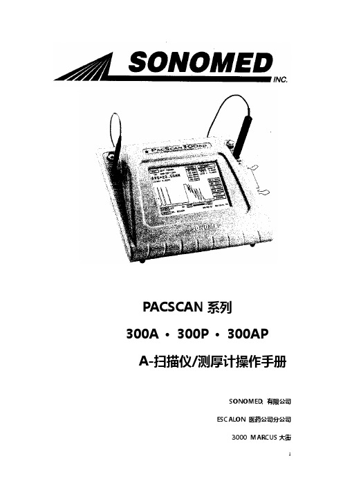
PACSCAN系列300A 〃 300P 〃 300APA-扫描仪/测厚计操作手册SONOMED, 有限公司ESCALON 医药公司分公司3000 MARCUS大街LAKE SUCCESS, NY 11042, USA电话 800-227-1285516-354-0900传真 516-354-5902版权所有© 2002、2003年Sonomed 有限公司保留所有版权无Sonomed 有限公司书面许可,任何集体与个人不得复制出版此出版物中的任何内容。
Sonomed 有限公司享有变更说明手册内容的权利在美国以循环证件的形式印刷DOC# 0300-A-1901-3D表格内容第1部分引言1.1 A-扫描仪使用特点 1-1 1.2 测厚计使用特点 1-2第2部分仪器启动2.1 打开包装 2-12.2 安全性注意事项 2-2仪器标识性条款本手册中使用的条款一般性注意事项一般性警告2.3 系统设臵 2-4连接附件工作打印机设臵电源增频检测使用触摸屏屏幕对比度调整日期与时间设臵第3部分 A-扫描仪操作与临床使用3.1 A-扫描仪选择设臵模式 3-13.2 校正 3-1 3.3 系统设臵 3-2进入用户信息系统进入病人信息系统3.4 病人准备 3-43.5 病人检查 3-4直接接触扫描,自动俘获模式直接接触扫描,手动模式水浸技术进行IOL计算打印3.6 错误类型及规避注意事项 3-11角膜压缩A-扫描模式检测模式第4部分测厚计操作与临床使用4.1 测厚计设臵模式 4-14.2 测量精确度与 4-1探针敏感性试验4.3 系统设臵 4-2进入用户信息系统进入病人信息系统测量偏差角膜测量速度4.4 病人准备 4-3 4.5 病人检查 4-3测量模式测量-单点单项读取测量-单点多项读取测量-多点单项读取测量-多点多项读取测量过程疑难解决打印4.6 检测对象 4-8角膜压缩A-扫描模式检测模式第5部分维护与维修5.1 常规维护 5-1系统一般检查清洁存储探针一般检查5.2 A-扫描仪功能性检测 5-2校正检测敏感性检测5.3 测厚仪功能性检测 5-3测量精确性检测探针敏感性检测5.4 疑难解答 5-55.5 质量保证 5-6第6部分系统详述生理性系统 6-1电系统 6-1环境系统 6-1接触界面 6-1显示器 6-1探针 6-1探针 6-1打印机(工作的) 6-1辅助零件 6-1A-扫描仪系统操作 6-2测厚仪系统操作 6-2符号 6-3附录速度表格附录-1IOL常数表格附录-3HAIGIS IOL 公式附录-5第1部分引言PACSCAN TM系列产品是由Sonomed公司引领生产的最新一代眼科测量仪器。
《Bosch Video Management System Operator Client V4
6.1
显示地图
6.2
控制 PTZ 摄像机
6.3
使用摄像机的窗内控制
Bosch Sicherheitssysteme GmbH
操作手册
目录 | zh 3
6 6 6
8
9 9 9 9
10 10 10 10
12 12 12 12 13 13 13 14 14 15 15 15 15 16 16 16 16 17 17 17 17 18 18
4
使用入门
本章介绍有关如何启动 Bosch Video Management System 和 Bosch VMS Archive Player. 的信息。
4.1
安装软件模块
注意 不要将 DiBos Web 客户端安装在任何 Bosch VMS 计算机上。否则,在 Web 客户端启动后,每个 Web 客户端计算机上的 Operator Client 将会崩溃。
4.3
启动 Operator Client
5
显示摄像机图像
5.1
在图像窗格中显示摄像机
5.2
在逻辑树中查找项目
5.3
排列图像窗格
5.4
显示报警图像窗口
5.5
启动手动录像
5.6
启动预配置的摄像机序列
5.7
启动自动摄像机序列
模式
5.10
使用数字变焦
5.11
保存单个图像
12 12.1 12.2 12.3
13 13.1
14 14.1 14.2 14.3
参考图像 对话框 选择搜索参数 对话框 ATM/POS 选项 对话框 选择虚拟输入过滤器设置 对话框 设备选择 对话框 事件选择 对话框 日志结果 对话框 选件 对话框 逻辑树 窗口 搜索 对话框 收藏夹树 窗口 导出树 窗口 地图 窗口 云台控制 窗口 监视器 窗口 图像窗口 图像窗格 时间链 窗口 移动搜索 对话框 导出视频 对话框 删除视频 对话框 防伪搜索 对话框 (仅限 VRM 录像) 保护视频 对话框 取消保护视频 对话框 移动搜索结果 窗口 视频搜索结果 窗口 报警列表 窗口 事件列表窗口 所用的图标
ESDPS用户手册
工程测量数据处理系统用户手册
5-1 道路测设功能及适用范围............................................................................. 43 5-2 作业流程......................................................................................................... 43 5-3 道路测设数据录入方法................................................................................. 44 5-4 道路测设报表成果输出................................................................................. 48 5-5 道路测设图形成果输出................................................................................. 50 5-6 关于路线测量断链......................................................................................... 51 第六章 公路设计...................................................................................................................53 6-1 路基超高及加宽计算.............................
Bosch Security Systems 软件手册 AM18-Q0635说明书
Bosch Security Systems
软件手册
目录 | zh 5
37 37 37 37 37 37 38 39 39 39 39 39 39 39 39 39 40 40 40 41 41 41
42 42 42 42 42 42 42 42 42 42 43 44 45 45
AM18-Q0635 | v5.6 | 2013.01
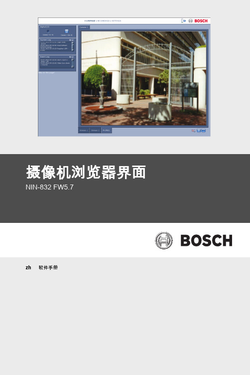
摄像机浏览器界面
NIN-832 FW5.7
zh 软件手册
摄像机浏览器界面
目录
1 1.1 1.2 1.2.1 1.3
浏览器连接 系统要求 建立连接 摄像机中的密码保护 受保护的网络
2
系统概述
2.1
实况页面
2.2
录像
2.3
设置
3 3.1 3.1.1 3.1.2 3.1.3 3.1.4 3.1.5 3.1.6 3.1.7 3.1.8 3.1.9 3.1.10 3.1.11 3.2 3.2.1 3.2.2 3.2.3 3.2.4
设置
Bosch Security Systems
软件手册
目录 | zh 3
12 12 13 13 13
14 14 14 14
15 15 15 16 17 18 19 20 20 20 20 20 21 22 22 23 23 24
26 26 27
AM18-Q0635 | v5.6 | 2013.01
网络 网络访问 自动 IP 分配 IP V4 地址 IP V6 地址 DNS 服务器地址 视频传输 TCP 速率控制 HTTP 浏览器端口 HTTPS 浏览器端口 RCP+ 端口 1756 Telnet 支持 接口模式 ETH 网络 MSS [ 字节 ] iSCSI MSS [ 字节 ] 网络 MTU [ 字节 ] 启用 DynDNS 提供商 主机名称 用户名 密码 立即强制注册 通知邮件 状态 高级 SNMP
(去石机)SGA10`15B-C说明书

一. 技术参数
SGA 使用说明书
型号 稻谷(t/h)
SGA10B-C 7
SGA15B-C 10
产量
糙米(t/h)
小麦(比重机用)
小麦(去石机用)
10 7~13
15 13~18
动力要求
振动电机 1 0.3 kw 振动电机 1 0.3 kw 振动电机 2 0.3 kw 振动电机 2 0.3 kw 风机电机 0.75 kw 风机电机 0.75 kw
15. 安全装置必须经常处在正常的工作状态,而不能移开,失效或不动作。若在 此种不良状态下工作,佐竹公司恕不付任何责任。
16. 进一步的防护规则,我们将在使用说明书中的安全防护部分作特别的说明。
以上说明仅供参考
由于规范的不断更新,本说明书印刷以后,有一些特别细节可能会改变,请 与佐竹公司进行核对。
目录
8
2. 安装地脚孔 SGA10-B
SGA 使用说明书
SGA15-B
单位:mm
图 5-3
3. 安装顺序 (1) 移动安装机器需用四个吊环螺栓。 (2) 去掉运输撑板 A 和 B。(图 5-2) (3) 确保机器水平放置。 (4) 固定机器在座架上(或地面上)。 (5) 在喂料门和卸料门安装风管,溜管。 (6) 在适当的地方安装石子收集箱。 (7) 接线时,必须要使机器接地。 (8) 检查是否有工具或杂物留存在机器中。 (9) 接入电源,确认各个马达的运转方向。 (10) 拧紧固定电机的螺栓所需的力矩为 170N•m(17kgf•m)。 (11) 再次确认机器安装是否水平。
面的上部末端。 10. 筛网能从原料投入侧抽出,机器前面必须要有 1500mm 的间距。
5
四. 工作原理
SGA 使用说明书
博世FlexiDomeDN IP网络摄像头操作指南说明书
55
7.7.1
iSCSI IP address (iSCSI IP 地址)
55
7.7.2
iSCSI LUN map (iSCSI LUN 映射)
55
7.7.3
Target IP address (目标 IP 地址)
56
7.7.4
Target node (目标节点)
56
7.7.5
Target LUN (目标 LUN)
56
7.7.6
Target password (目标密码)
56
7.7.7
Initiator name (启动程序名称)
56
7.7.8
Initiator extension (启动程序扩展)
56
7.7.9
Decoupling the drive used (断开使用的驱动器)
57
7.7.10 Storage information (存储信息)
4
摄像机设置
4.1
摄像机定位
4.2
焦距和焦点
4.3
基本设置
博世安保有限公司
操作指南
| 中文 3
13 14 14 15 15 15 16 16 16 16 16 16 16 17 17 17 17 17 17
18
19 20 20 20 21 21
22 22 23 23
V 1.0 | 2006.12
4 中文 |
74
7.13.6 Send e-mail for testing (发送电子邮件进行测试)
74
7.14
Service Settings (服务设置)
74
7.14.1 Network (网络)
EinScan-SP桌面3D扫描仪用户手册说明书
EinScan-SPDesktop 3D ScannerUser Manual1. Device List and Specification (3)1.1. Device List (4)1.2. Specification Parameter (5)1.3. System Requirement (6)2.Installation Notes (7)2.1. Hardware Installation (8)2.2. Software download (11)2.3. Software Installation (12)3. Software Introduction (13)3.1. Scan Preparation (14)3.2. First Scan (15)3.2.1. Help Mode for Beginners (15)3.2.2. Obtain License File (15)3.2.3. Operation Procedure (15)3.3. Drop down Menu (17)3.3.1. Language (17)3.3.2. TeamViewer (17)3.3.3. Feedback (17)3.3.4. User Setting (18)3.3.5. Factory Default (18)3.3.6. Einscan Community (19)3.3.7. About (19)4.Calibration (20)4.1. Calibration (21)4.2. Calibration Precaution (24)5. Fixed Scan (25)5.1. Help Mode for Beginner (26)5.2. Before Scaning (27)5.3. Scanning (29)5.3.1. Start Scan (29)5.3.2. Edit Tool (29)5.3.3. Manual Align (31)5.3.4. Delete Current Data (31)5.3.5. Pause (31)5.4. After Scanning (31)5.4.1. Mesh (31)5.4.2. Data Post Processing (33)5.4.3. Save Your Data (35)5.4.4. Share Your Data (36)5.4.5. Project (37)5.4.6. Back to home (37)5.5. Others (37)5.5.1. Mouse Operation Prompts (37)5.5.2. Hot Key (37)5.5.3. Points and Triangles (38)5.5.4. Help (38)5.5.5. Model Viewer (38)5.6. Work Offline (39)6. FAQ (40)7. Safety Precautions (42)8. Help (44)1Device List2◆Step 1. Place the scanner head onto the bracket.◆Step 2. Insert calibration board onto the board holder . NOTE : Rotate the calibration board only while calibration.◆Step 3-1. Turntable and Scanner installation.1)Place the turntable ontoscanner stand.2)Screw the scanner intothe socket on thestand.3)Plug power cord into outlet and the back of scanner;Plug USB cable into back ofscanner and computer USB port;Plug USB cable into back of scanner, and turntable.Step3-2. Setting scanner on tripod for fixed scan, turntable coded targets and markers align mode.1)Screw the scanner head onto tripod.2)Plug power cord into outlet and the back of scanner;Plug USB cable into back of scanner andcomputer USB port;Plug USB cable into back of scanner, and turntable.Hardware Installation◆Hold on the touch switch for about one second to turn the scanner on;◆Double-click on the touch switch and stay for one second each time to turn the scanner off.Software downloadFirstly, enter the Support page: /support. Click “Software download”, as shown below:Secondly, please complete the registration, if registered, click log in.After take the survey, it will enter the page /software-downloadFinally, click the icon to jump to the page of any file to download the software.Double click installation package, drag the "EinScan-S" to the Application.Double click installation package, drag the "EinScan-S" to the Application. When installation is finished, there will be a shortcut of thesoftware on the Application .In the next step, connect the device and check whether the camera driver installation is successful, click the Mac logo on the top left corner of the desktop, select 'about the machine', open the 'overview' system report,and see if the camera's name is normally displayed under the 'camera' in the 'hardware'Open the Application, delete EinScan-S, as shown below.Software Installation3Scan Preparation(1) Fixed Scan ( With Turntable ): This mode is recommended for objects within the size of200*200*200mm.(2) Fixed Scan ( Without Turntable ): This mode is recommended for objects over the size of200*200*200mm, as well as a comparative stable environment (without obvious vibration) are required.Do not touch or move the object being scanned while the scan is in progress. Do not scan moving object, size smaller than 30*30*30mm,and objects with hollow pattern design .Stick mark points on the object in random, avoiding sticking in one line.Public areas alignment require at least four mark points. While placing the points, uniformly stick the mark points on the object, and make sure that in each single scan area has at least 4 points.Before scan objects in transparent, semi-transparent or black shall spray on the surface.Choose the device “EinScan-SP”, as shown below.3.2.1.Help Mode for BeginnersClose Help Mode for Beginner by clicking the top right corner . To open Help Mode for Beginner, go to Setting -> User Setting ->Help-mode for beginners3.2.2.Obtain License FileWhen a warning of license file doesn’t match the scanner pops up when entering scanning mode, the license file can be acquired by clicking “ Activate”.3.2.3.Operation ProcedureClick from the upper left to open drop down menu.nguageThis software version is including Simplified Chinese, Chinese, English, German, Japanese, Spanish, French, Korean, Russian and Turkish. Language can be switched in the choose device type interface.3.3.2.TeamViewerBy clicking TeamViewer, you can go to the TeamViewer interface directly without installation.3.3.3.FeedbackIf you have any questions, or suggestions, please share with us by clicking “Feedback”. Leave your email in “ My E-mail”3.3.er SettingHelp Mode for BeginnersHelp Mode for Beginner is the default selection, which is to guide the new users make a scan completely step by step. Close Help Mode for Beginner by clicking the top right corner. To open Help Mode for Beginner, go to Setting -> User Setting ->Help-mode for beginnersUser Experience ProgramTo help us improve the quality and user experience of Einscan, we hope to be allowed to collect usage information to Einscan Team. This information will not identify you and does not include your project data. By default, this checkbox is selected, and we strongly recommend you to select it.3.3.5.Factory DefaultSystem setting (brightness, turntable steps), calibration data will restore to the factory default settings. Language will be changed into English as default. Factory Default will require software restart.3.3.6.Einscan CommunityOfficial Website ( /) refers to SHINING3D official website for product and information.Community ( /einscan-experts-forum ) refers to SHINING3D forum for all EinScan users to discuss and share the experience.Facebook (https:///groups/einscan) refer to facebook for Einscan users to discuss and share the experience.3.3.7.AboutSoftware version information, and technical support mail can be found here.4Click ‘Calibrate’ to enter the interface of calibrate.If there is no calibration data, choose device type and it will enter the calibration interface automatically.The interface of calibrate:Calibrating your scanner is important in order to get accurate scan results. The following describes the three steps required to successfully calibrate your device.Follow the software operation guide, adjust the distance between the projector and calibration board, and the cross from scanner should target at the calibration board n clearly.Place the calibration support and board in the center of the turntable as shown in Figure A. Check that the calibration board is located at the center of the turntable with the Figure A pattern facing the scanner and click “Snap”. Do not interfere or touch the calibration board during the calibration sequence.Don’t move th e support. Only rotate the calibration board.After the 1st calibration sequence, the turntable will stop and the display will show what is in FigureB. Being careful not to move the support, remove the calibration board, rotate it 90°counterclockwise and place the board back onto the support as shown in Fig. B.Note:Don’t move the support. Only rotate the calibration board.Being careful not to move the support, remove the calibration board, rotate it 90°counterclockwise and place the board back onto the support as shown in Figure C.Upon completion of the 3rd calibration sequence, the software will automatically calculate and archive the current conditions. This calculation may take several seconds but once complete, you are ready to start automatic turntable scanning.When calibration is finished, the software will close the calibration window automatically and enter the scan mode selection page.If the calibration fails, please try to re-calibrate following the instructions above. If calibration fails again, please contact your local support representative.Camera CalibrationCalibration PrecautionsYou must finish all the calibration steps according to the instruction when you calibrate at the first time. Situations as below need do calibration again:5Help Mode for BeginnerChoose Fixed Scan, as shown below, click “Next”.Help Mode for Beginner is the default selection, which is to guide the new users make a scan completely step by step. Close Help Mode for Beginner by clicking the top right corner. To open Help Mode for Beginner, go to Setting -> User Setting ->Help-mode for beginnersUnder the Help Mode for Beginner, following the guidance step by step, you will finish a scan following: New Project -> Texture/Non-texture ->adjust brightness -> start scanning -> Edit -> ->Continue Scan/Mesh -> Mesh type: Watertight/ Un-watertight -> Post Processing -> Save dataEnter the interface of New Project and Open Project, the default project save location is the desktop, then it will remember where the user last created a new project.Click “New Project”, e nter the project name, then click ‘Save’ to enter the interface of Non-texture Scan and Texture Scan selection.Choose ‘Texture scan’ to enter the white balance test.When scanning a colored object, you’ll n eed to perform a white balance test to achieve better scanning results. Place a sheet of white paper as shown below on the calibration plate and click “Restarting white balance test?”.After the white balance test has completed, you are free to continue with the texture scan.Adjust the distance between the object and device (suitable working distance is 290 ~ 480mm), until the cross is clearly to be seen on the object.Most users will find that the automatic settings work just fine but for more complex objects or lighting conditions, you can manually adjust scanner settings.Choose your desired brightness setting if the object is over or under exposed. Click “Apply” to confirm, or click ” Cancel ” to not save.Enter the interface of fixed scan, check “With Turntable”Work distance:Adjust the distance between the object and device (suitable working distance is 290 ~ 480mm), until the cross is clearly to be seen on the object.Camera viewportTick to display the right camera viewport and texture camera viewport. The left camera viewport always display.Click in the lower right corner of the camera viewport to zoom the camera viewport Adjust BrightnessDrag the button to adjust the brightness. The brightness is appropriate at the right scan distance: equipment against objects, the cross is clearly in the brightness viewing window. This function is the same as the adjust brightness when new a project.If you don’t choose “With Turntable” option, you will get single piece of data; if choose this option, the scanner will use turntable to scan and choose turntable steps.Turntable StepsBefore scanning, you can set the scan times per round underturntable scan. The default setting is 8 times.Align ModeThe default is turntable align mode ,you can also choose markers ,turntable coded targets and feature align mode. Align mode can be re-selected after the turntable has rotated one circle. You can click for help.If you choose turntable coded targets, you must set the scanner on tripod.HDREnable HDR brightness can scan bright and dark objects. The function is the same as Adjust brightness “Bright&Dark ”.5.3.1. Start ScanClick the button or press space button to start scanning. After the turntable has rotated one circle ,you can change with turntable or not, turntable steps and align mode.5.3.2. Edit ToolEdit buttons:①Deselect ②Revert ③Delete ④Undo ⑤Show/HideStripes ⑥Shift + Left mouse: choose dataYou can edit the current part data after each scan. You can do the below edition if the data has excess parts, both data and mark points can be edited.SHIFT+Left mouse:Select excess parts, the selected section is displayed in red, as shown below.Delete selected dataClick the button and “DELETE”in the keyboard to deleteselected data.UndoYou can only undo the last deleted data.Show/Hide StripesClick the button to switch the texture display and hide. Non-texture scan, there is no such button.End single-piece editClick to save data and exit the single-pieceedition; Click, delete the current scan dat.After end the single-piece edit, the right toolbar willdisplay, and now can edit the whole scan data. Thespecific operation is the same as the single-piece edit.5.3.3. Manual AlignAlignIf automatic alignment failed during scanning, you can use manual align. Click the buttonto open Manual Align view port on the left side of the software. Keep SHIFT down, and click left mouse button to select at least 3 non-collinear corresponding points in the 3D preview windows for Manual align, As shown on the right.5.3.4. Delete Current DataDelete the Current DataIf you are not satisfied with current scanning data, or there is not enough overlappingregion for registration, click the button to delete current data and then change the position of the scanner or the object to scan again.When auto scan mode is scanning, you can click the button to stop the current scan. The current data will be deleted directly.5.3.5. PausePauseClick the button, scanning will pause; Click again to resume scanning.5.4.1. MeshWhen the scan is completed, click the botton, proceed to post-processing. You will see two modes after clicking the button: Watertight and Unwatertight. Watertight usuallyslower than unwatertigt. Texture scan mode will take more time compared to Non-Texture scan mode.Note :When import project, clickbutton the fixed scan is remove the singledata; Auto scan is to delete all the data.WatertightClosed model can be printed directly. After choose this mode, you should select theobject details.Select High for objects with fine texture, select Med or Low for objects in smooth surface or with less detail. The time for data processing is in relation to the detail setting. The higher the level of details is, the longer time the processing takes. It may keep for a long time in 95%, please be patient.Select the object details:UnwatertightUnclosed model. The following picture is the watertight and unwatertight model.Watertight UnwatertightTexture watertight results :5.4.2.Data Post ProcessingAfter meshing, the following dialogue box of data post processing will appear. You can simplify the data per your request, do fill holes, sharpening or smoothing operations. Unwatertight and watertight, the post processing of the interface as shown below.Unwatertight WatertightData simplificationAfter simplification, the polygon numbers, size and surface detail of data will be reduced accordingly. Check the simplify check box and set the ratio, the default is 100%.The comparison of detail between before simplification and after simplification (at 30% simplify proportion).Before simplification After simplificationFill holesThe default does not check the mark point and fill hole, check the fill hole you need set perimeter, choose 10-100mm perimeter to fill the hole, less than the perimeter of the hole will be filled. Mark point fill hole as an example.AfterBeforeSmoothThe data to denoise processing, improve data quality, the figure before and after smoothing:Before smooth After smoothSharpenImprove the overall clarity of the data, the figure below before and after sharpening:Before sharpen After sharpen5.4.3.Save Your DataBefore merging can save data as asc single. After merging, it can be saved as asc, stl,ply and obj. To save color texture, please select Ply and obj.ScaleScaling the volume of scanning data, while the quantity of triangular facets and size of data will not be changed.Scaling result as reference: From left to right shows double size, original size and half size respectively.Scale window Scale result5.4.4. Share Your DataClick the button after merging to share data, it will show the dialog as below.You can share your model to Sketchfab, while model title, username and user passwordare required. Register an account and look at the shared model at .5.4.5. ProjectYou can new or open projects. The default project location is the desktop, then it will remember where the user last created a new project.5.4.6. Back to homeIf you want to change the scan modes, click the button to go back to the homepage to select the scan mode.5.5.1. Mouse Operation PromptsLower left corner of the interface is the mouse operation prompts: After scanned or imported project, the prompt text is as follows: Hold down the left mouse button : Rotate the object; Hold down the middle mouse button : pan the object;Hold down the mouse wheel : Scroll up and down to the object; scroll down to enlarge the object;Hold down the Shift + left mouse button : select the area on the object; Delete : Delete the selected area. Manual align, the prompt text is as follows:Press and hold shift + left mouse click : Select point to start manual align5.5.2. Hot KeySpace button: To start scan or during single-piece edit to save data and exit the single-piece edition.5.5.3.Points and TrianglesCurrent Points and TrianglesWhen scanning it will show the current points and currenttriangles in the lower right corner. When you edit the scan data, the current points and the current triangles change in real time.5.5.4.HelpClick this button to get the operation manual and notes in more detail under thecurrent step.The following picture shows the help information of new project.5.5.5.Model ViewerEinscan software can be a 3d viewer for ASC, OBJ, STL format file. Drag the 3d model to Einscan software under scanning mode interface.You can use software without scanner connection. You can do edition, manual align, delete, mesh, save data, share data and so on.6FAQ1.What if no scan data when the turntable has rotated one circle?Solution: Please make sure that the object won’t block the mark points on the turntable. Or, there will be no fringe pattern, while turntable will be still rotating. If the align mode is mark point, please make sure that the marks on the turntable are covered, so as not to affect the scanning. Make sure that in each single scan area has at least 4 points.2.What if the merging fails without mark points when the turntable has rotated several circles or when it is under f ixed scan mode?Solution: Try to make sure there are at least 1/3 overlap between the current scan area and the previous scan area and the object surface should be featured. For objects which are symmetric and without rich features, using mark points or manual merger is recommended.3.How to scan objects in transparent, semi-transparent or black?Solution:Scan before spraying on the surface.4.Under auto scan mode, if the turntable is not moving, but with a humming sound, how to solve?Solution:Disconnect power line and connect again in few seconds.7Safety PrecautionsKeep well-ventilation. Environment temperature shall below 40 Celsius degree, and do not use the device under an environment with flammable or corrosive gases or another similar environment.Please grab and place gently in the proper position, and do not squeeze it. Prepare precautions like sunscreen, rain-proof, shock-proof and etc. No matter on sunny or rainy days.If the device could not function correctly, fixing the device by opening it by yourself is not allowed. The device shall be repaired by professional technicians or under their instruction.You should send the device to facilities with qualification for recycling it instead of dropping into the household garbage when it is scrapped.8HelpEmail:*****************************More scanning information can refer to ---Support。
OpticSlim 扫描仪使用手册说明书
扫描仪使用手册OpticSlim注册商标© 2022 版权所有,翻印必究。
未经允许不得翻印本手册其中任何一部份。
ABBYY®FineReader®进行OCR处理,©2022 ABBYY。
ABBYY和FineReader是ABBYY Software,Ltd.的商标,可能已在某些司法管辖区注册。
本手册内容提及之公司名称和注册商标均各自属于他们的公司和所有者。
免责声明本手册中出现的所有内容都经过仔细考证,尽管如此,我们不排除可能由于疏忽、偶然情形或其它原因造成本手册出现错误、遗漏、或不恰当表述,我们对这类错误、遗漏或不恰当表述不承担任何责任和义务。
本手册中的内容可能发生改动,恕不另行通知。
我们将不承担任何法律责任若用户未遵循本手册中的操作指示。
版权某些文件(如支票、钞票、身份证、国债或政府文件等)的扫描可能受到法律禁止或构成犯罪。
当您在扫描各种书籍、杂志、期刊时,建议您尊重并遵守有关著作权的各项规定。
环境保护关于回收或处置的信息,请向当地经销商或供货商咨询回收和处置的信息。
本产品的设计和制造得到持续改进,以符合新的环保要求。
我们致力于生产达到全球环保要求的产品。
请您向当地相关部门咨询报废该类物品的处理方法。
本产品的外包装可被回收再利用。
目录介绍 (1)如何使用本手册 (1)本手册所使用的标示 (1)图标说明 (2)安全注意事项 (2)系统需求 (3)原厂附件 (3)扫描仪概述 (4)第一章、安装扫描仪 (6)软件安装需求 (6)硬件需求 (6)安装与设定扫描仪 (7)第一步、连接您的扫描仪和计算机 (7)第二步、安装软件 (9)第三步、测试扫描仪 (10)安装其它软件 (10)第二章、执行扫描 (11)准备稿件 (11)检查稿件状态 (11)放置稿件 (12)使用平台 (12)扫描稿件 (12)用TWAIN来完成扫描 (13)用扫描仪按键或DocAction的”执行”菜单来完成扫描 (14)从DocAction 窗口中使用左侧排列的图标按钮进行扫描 (16)第三章、扫描仪的保养和维护 (17)清洁扫描仪 (17)清洁用品 (17)清洁平台 (18)校正扫描仪 (18)待机模式 (19)第四章、常见问题 (20)扫描仪的连接 (20)附录A:规格 (21)附录B:售后服务和保证 (22)服务与支持信息 (22)产品保证声明 (22)FCC 射频干扰声明书 (23)感谢您选购本公司的扫描仪。
Leica IP S 产品说明书
我们没有义务根据最新技术发展定期和持续不断地更新当前使用说明书,或为客户提供本使用 说明书的更多副本、更新等。
在按照国家法律制度适用于每宗个案允许的范围内,我们对本使用说明书中所含的错误的陈述 图画、技术图示不承担法律责任。需要特别指出的是,对于因遵从本使用说明书的陈述或其他 信息所造成的任何直接或间接经济损失或损害,我们概不承担责任。
Leica IP S
3
目录
1. 重要信息 ............................................................................................................................................... 6
4. 仪器安装 .............................................................................................................................................24
2.1 安全说明 ...............................................................................................................................................................................11 2.2 警告 .........................................................................................................................................................................................12
石博士石材扫描仪用户手册(中文版)
使用手册
小心:
如果电池的型号不正确可能有爆炸的危险。 请按照使用地区的法规来处理不要用的电池。 仅在使用本产品时使用电池。 在温度 0°C - 40°C 的情况下,保存电池。 禁止在高温下(直热的阳光下或很热的汽车中)使用或放置电池,否则可能会引起电池过 热,起火或功能失效,寿命减短。 禁止在强静电和强磁场的地方使用,否则易破坏电池安全保护装置,带来不安全的隐患。 如果电池发生泄漏,电解液进入眼睛,请不要揉擦,应用清水冲洗眼睛,并立即送医治疗, 否则会伤害眼睛。 如果电池发出异味,发热,变色,变形或使用,贮存,充电过程中出现任何异常现象,立即 将电池从装置或充电器中移离并停用。 如果电池弄脏,使用前应用干布抹净,否则可能会导致接触不良功能失效。 废弃之电池应用绝缘纸包住电极,以防起火,爆炸。
石博士石材扫描仪 使用手册
石博士-001
商标 Microsoft 是微软公司的美国注册商标。 Windows 和 Windows XP, Windows Vista, Windows 7 是微软公司的美国注册商标。 IBM,IBM PC 是国际商务机器公司的注册商标。 本文中其它厂牌和产品名称皆为各相关厂商的商标或注册商标。 著作权 版权所有,未经厦门巨奥电子商务有限公司(以下简称“巨奥商务”)授权,不得将本文内容以任何形式 复制、改编、或翻译成任何文字。
3. 扫描仪的操作.................................................................................................... 1
3.1 开启扫描仪的电源 .................................................................................... 1 3.2 选择你需要的扫描设定............................................................................... 1 3.3 扫描你的石材.......................................................................................... 2 3.4 在液晶屏幕预览图像 ................................................................................. 3 3.5 浏览或下载扫描的图像 (PC)........................................................................ 4
扫描器 说明书
掃描器使用手冊目錄TWAIN對話框 (3)預覽視窗及控制設定鍵 (4)掃描設定鍵及掃描/預掃鍵 (5)主要設定頁 (6)影像調整頁 (10)影像處理頁 (14)關於驅動程式 (15)使用批次掃描 (16)疑難排除 (18)TWAIN 對話框T W A I N 為掃描器軟體介面的標準。
T W A I N 提供一種介於應用軟體及掃描器之間的溝通管道。
經由T W A I N ,您可進行硬體及軟體間的通訊,例如在使用應用軟體(Photo Express 或FINEREADER 等)來掃描影像或文件時,您可透過T W A I N 叫出掃描器,並執行掃描。
掃描後的影像或文件則會自動出現在應用軟體的主要螢幕上。
此時,您便可開始進行影像或文字編輯。
掃描框選工具鍵可框選一掃描區域批次掃描鍵最多可建立十個掃描區以供掃描放大縮小鍵在預覽視窗中可放大或縮小影像示顯縮放比例語言鍵可選擇使用的語言離開掃描框選區可檢視預掃的影像及選擇最後的掃描範圍覽預視窗掃描設定預掃鍵掃描鍵說明批次掃描鍵此功能可讓您在不同的掃描控制之下多次掃描文件的任何部份。
離開離開此程式。
掃描框選工具鍵可在預覽視窗中框選一個掃描區域。
利用滑鼠移動此框線的任何一邊或是四個角落並拖曳出您想要的長度及寬度。
若想移動整個框線,只要將滑鼠的游標定位在框內,再按住滑鼠左鍵來拖曳到想要的位置即可。
放大縮小鍵使用此放大工具可將預掃影像放大或縮小。
您可從放大或縮小之後的影像正確的框選想要掃描的範圍。
預覽視窗及控制設定鍵預覽視窗可供顯示預掃影像。
在第一次掃描前最好能先預掃一次,如此可利用預掃後影像,正確的框選出欲掃描的範圍,並可藉以觀察各項調整影像功能對影像的影響效果。
說明在線上提供有關掃描器及軟體的輔助說明。
語言選擇在螢幕上所顯示的語言。
掃描設定鍵及掃描/預掃鍵先前鍵將最後一組儲存的掃描設定值重新載入。
還原鍵將影像設定還原成原始的內定值。
設定值鍵將所有的控制設定值同時顯現出來。
- 1、下载文档前请自行甄别文档内容的完整性,平台不提供额外的编辑、内容补充、找答案等附加服务。
- 2、"仅部分预览"的文档,不可在线预览部分如存在完整性等问题,可反馈申请退款(可完整预览的文档不适用该条件!)。
- 3、如文档侵犯您的权益,请联系客服反馈,我们会尽快为您处理(人工客服工作时间:9:00-18:30)。
5.1 常见问题与答复 ....................................................................................... 1 5.2 排除错误信息.......................................................................................... 3 5.3 技术服务 ............................................................................................... 4
4. 保养 .................................................................................................................. 1
4.1 校正本产品 ............................................................................................ 1 4.2 清理滚轮及玻璃镜面 ................................................................................. 2
欧盟 (EC) 符合性声明 本产品标示CE标志说明符合下列EU指令
低电压指令 2006/95/EC 电磁兼容性指令 2004/108/EC 本产品的CE符合性需搭配巨奥所提供有CE标志的电源供应器。
本产品是否适用于高海拔和热带地区使用,需视与之匹配的计算机或供电设备(如:适配器)是否满足高海拔 和热带地区要求。 若设备标示有下列的警告标识表示:
v
目录
1. 简介 .................................................................................................................. 1
1.1 包装内容 ............................................................................................... 1 1.2 俯视图.................................................................................................. 2 1.3 侧面图.................................................................................................. 3 1.4 底部图.................................................................................................. 3 1.5 LED指示灯 ............................................................................................ 4
iiBiblioteka 用手册聯邦通信委员会 (FCC) 符合性信息声明 此项设备已经测试,并确认其符合FCC法规Part 15之Class B 数字装置的规定。这些限制的设计旨在提供 合理的防护,避免此设备在居家安装时所产生之有害干扰。此设备会产生、使用,并放射无线电波频率能 源,而且,如果未依照说明手册安装及使用,可能会对无线通讯造成有害的干扰·。但是,并不保证特别的 安装不会发生干扰。 如果透过关闭和开启设备确认此设备对无线电或电视接收造成有害干扰,使用者可以 下列一种或多种方式修正干扰:
3. 扫描仪的操作.................................................................................................... 1
3.1 开启扫描仪的电源 .................................................................................... 1 3.2 选择你需要的扫描设定............................................................................... 1 3.3 扫描你的石材.......................................................................................... 2 3.4 在液晶屏幕预览图像 ................................................................................. 3 3.5 浏览或下载扫描的图像 (PC)........................................................................ 4
iv
使用手册
小心:
如果电池的型号不正确可能有爆炸的危险。 请按照使用地区的法规来处理不要用的电池。 仅在使用本产品时使用电池。 在温度 0°C - 40°C 的情况下,保存电池。 禁止在高温下(直热的阳光下或很热的汽车中)使用或放置电池,否则可能会引起电池过 热,起火或功能失效,寿命减短。 禁止在强静电和强磁场的地方使用,否则易破坏电池安全保护装置,带来不安全的隐患。 如果电池发生泄漏,电解液进入眼睛,请不要揉擦,应用清水冲洗眼睛,并立即送医治疗, 否则会伤害眼睛。 如果电池发出异味,发热,变色,变形或使用,贮存,充电过程中出现任何异常现象,立即 将电池从装置或充电器中移离并停用。 如果电池弄脏,使用前应用干布抹净,否则可能会导致接触不良功能失效。 废弃之电池应用绝缘纸包住电极,以防起火,爆炸。
3.5.1 基本计算机系统需求………………………………………………………………………………..5 3.5.2 连接计算机后………………………………………………………………………………………….5 3.6 浏览或下载扫描的图像 (iPad) ..................................................................... 6 3.7 选择你需要的扫描设定............................................................................... 7 3.7.1 分辨率…………………………………………………………………………………...7 3.7.2 语言……………………………………………………………………………………………………….7 3.7.3 关闭屏幕时间…………………………………………………………………………………………..8 3.7.4 省电模式………………………………………………………………………………………………….8 3.7.5 自动镜像校正…………………………………………………………………………………………..9 3.7.6 校正扫描仪……………………………………………………………………………………………..9 3.7.7 格式化内存卡………………………………………………………………………………………….10 3.7.8 恢复出厂值…………………………………………………………………………………………….10 3.7.9 关于本机……………………………………………………………………………….11
石博士石材扫描仪 使用手册
石博士-001
商标 Microsoft 是微软公司的美国注册商标。 Windows 和 Windows XP, Windows Vista, Windows 7 是微软公司的美国注册商标。 IBM,IBM PC 是国际商务机器公司的注册商标。 本文中其它厂牌和产品名称皆为各相关厂商的商标或注册商标。 著作权 版权所有,未经厦门巨奥电子商务有限公司(以下简称“巨奥商务”)授权,不得将本文内容以任何形式 复制、改编、或翻译成任何文字。
“仅适用于在海拔 2000m 以下地区使用”
“仅适用于在非热带气候条件下使用”
iii
使用锂离子电池警告及注意事项
警告: 危险警告:为防止电池可能发生泄漏,发热,爆炸,请注意以下预防措施: 严禁将电池浸入海水或水中,保存不用时,应放置在阴凉干燥的环境中。 禁止将电池在热高温源(如火、加热器)旁等使用、留置或丢入。 充电时请选用锂离子电池专用充电器。 严禁颠倒正负极使用电池。 严禁将电池直接接入电源插座。 禁止用金属直接连接电池正负极短路,任何时候禁止短路电芯,它会导致电芯严重损坏。 禁止将电池与金属,如发夹,项链等一起运输或贮存。 禁止敲击或抛掷,踩踏电池等。 禁止直接焊接电池和用钉子或其它利器刺穿电池。 禁止与液态锂离子或不同型号的聚合物锂电池混合使用。 禁止使用已损坏的电芯。 禁止弯折顶封边,禁止打开或破坏折边,禁止导折电芯折边底部。 禁止坠落、冲击、弯折电芯。 电池外壳设计和包装禁止损伤电池。 在任何情况下不得拆卸电芯。 更换电芯应由电芯供货商或设备供货商完成,用户不得自行更换。 电池应远离小孩。 导电组件与电池两侧封边接触必须绝缘。
保证 本书内容若有更动,巨奥商务将不另行通知。 巨奥商务对本文件内容不做任何保证,包括(并不限于)对某项特殊目的的适用性的隐含保证。 对因此造成的错误,或因装修、效能或本产品使用上造成的不固定或严重损害,巨奥商务不负任何责任。
