最新圈存机维修手册更多插图
圈存一体机安装配置说明书-移动4g

圈存一体机安装配置说明书一.开关机1.设置自动开机圈存机上电启动后按“del”键进入CMOS,选择“Power Management Setup→Peripherals Activities→RTC Alarm Resume”项改成“[Enabled]”,然后设置日期和时间,例如统一设置为每天早晨6:00自动开机,将Date(of Mouth)[0],Resume Time (hh:mm:ss)[6:00:00]即可。
圈存机开机设置使用usb-hdd启动////////若first boot 下没有,将带系统的u盘插上,选择harddisk,然后在hard disk boot priority 下才会有usb-hdd选项。
开机使用小内存系统进入,需要几分钟时间。
运行4gyindong文件夹下的ghost文件选择local—>disk->from image->选择4gyindong下的备份文件20101011.gho。
2.触摸屏程序和更新包1).以root用户登录,然后打开终端//***以下步骤可远程执行操作。
用vncviewer登录,密码szpbq8。
***/////将tk-8.4.9-3.i386.rpm和lib4Byte_7PSAM.tar.gz这两个个文件放到xzx的目录下。
解压缩更新包需在root 用户下执行进到cd /home/xzxtar -zxvf lib4Byte_7PSAM.tar.gzcd lib4Byte_7PSAM //进入到这个目录下。
sh updatelib.sh2).在终端提示符进入相应目录,然后执行:/*目录不固定,在文件对应的目录下即可*/cd /home/xzx/ 下rpm -ivh tk-8.4.9-3.i386.rpmcd /home/xzx/install/touch-driver/ 下执行rpm -ivh sharutils-4.2.1-12.i386.rpm**************************************************************************************** 若装有红外屏的程序,需要进行卸载操作:cd /home/xzx/install/touch-driver/IRTOUCH_Touchscreen_Driver_for_Linux/下执行卸载操作---执行sh setup.sh uninstall 执行卸载命令*************************************************************************************** cd /home/xzx/install/touch-driver/Fedora_4/sh touchkit.setup.sh3).等程序不在继续执行,安装过程中会提示用户选择安装接口类型,选择2(FULL MODE),安装完毕需重启机器生效,等所有配置完成后重启。
康艺2600维修手册
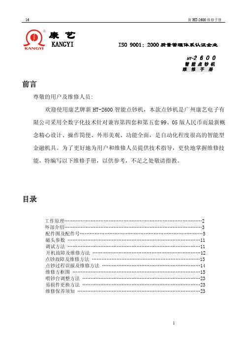
⑴6路磁性无次数 ⑵6路磁性次数偏低 ⑴4和5路磁性次数同时为 0 次 ⑴轮干扰 ⑵6路磁性次数偏高 ⑴4、5路磁性次数不够 ⑵1、2路AD电压偏高
⑴检查6路磁头是否开路或变值 ⑵检测 6 路磁性电路工作是否正常 (如:C38、C70 和 IC U12 324 等元件 ) 重调6路磁头或检测 6 路磁性电路 ⑴4路和5路磁头开路 ⑵4路和5路排线开路或接触不良 ⑶检测 4 路和 5 路磁性电路 用酒精清洗压钞轮 ⑴检查磁头是否变值 ⑵主板上R1140 电阻换成180K ⑶主板上C70 电容变值 调4、5路磁头间距 重调1、2路AD电压
更换发射管
Q8 的 b 极电压为 4.26V 左 右 和 CPU ④ 脚 电 压 为 0.13V(低电平)
是
检查 5V 供电电源 否
Q8 坏
CPU 坏
2、 接收管部分
档住接钞传感器开机,显示“E23”情 况 下 , 用万用表测量 P3 的⑤、⑥脚间电压和⑦、⑧ 脚间电压为 0.1~0.45V 之间
C46
更换CPU 更换晶振或电容 检查供电电源是否正常(见方框图二) 更换CPU
12
16
七、点钞故障及维修方法:
新 HT-2600 维修手册
故障现象
放钞票在喂钞台上 捻钞轮和接钞轮都
不转
放钞票在喂钞台上 捻钞轮转而接钞轮
不转 放钞票在喂钞台上 接钞轮转而捻钞轮
不转 大电机不刹车 点钞不计数(计数显 示始终为0)
接钞台有钞票(预置状态下) 取出钞票
⑴钞票宽度不符 ⑵钞票有缺口 ⑴电机响 ⑵轴承响
剔除不符宽度钞票 剔除有缺口钞票 更换电机 更换轴承
13
16
新 HT-2600 维修手册
八、 点钞过程中误报及维修方法:
设备维修手册
设备维修手册第一章:引言设备维修手册是为了指导用户在设备出现故障或需要维护时提供支持和指导。
本手册旨在提供详细的步骤和说明,以确保设备的正常运行和延长其使用寿命。
在阅读本手册之前,请确保您已经熟悉设备的基本操作和安全要求。
第二章:安全须知在进行设备维修之前,请务必遵循以下安全须知:1. 关闭设备并拔掉电源插头。
2. 确保维修工作区域干燥、通风良好,并远离易燃物。
3. 使用适当的个人防护装备,如手套、护目镜和防护服。
4. 仅使用经过训练和授权的人员进行设备维修。
5. 遵循设备制造商提供的维修指南和建议。
第三章:故障诊断与排除1. 设备无法启动1.1 检查电源线是否连接正常。
1.2 检查电源插座是否工作正常。
1.3 检查设备的电源开关是否打开。
1.4 检查设备是否存在电源故障,如电池电量不足或电源适配器损坏。
2. 设备运行缓慢或卡顿2.1 清理设备内部的灰尘和杂物。
2.2 检查设备的存储空间是否足够。
2.3 关闭不必要的后台应用程序。
2.4 更新设备的操作系统和应用程序。
3. 设备无法连接到网络3.1 检查网络连接是否正常。
3.2 重启设备和网络设备。
3.3 确保输入正确的网络密码。
3.4 检查设备的网络设置是否正确。
第四章:常见问题与解决方案1. 设备出现蓝屏或死机1.1 按住电源按钮强制重启设备。
1.2 卸载最近安装的应用程序或更新。
1.3 恢复设备到出厂设置。
2. 设备无法充电2.1 检查充电线和充电器是否正常工作。
2.2 清洁设备充电口和充电线插头。
2.3 尝试使用不同的充电器和充电线。
3. 设备屏幕出现色彩异常3.1 调整设备的屏幕亮度和色彩设置。
3.2 清洁屏幕表面。
3.3 更新设备的显卡驱动程序。
第五章:维护与保养1. 定期清洁设备表面和内部。
2. 避免将液体或小颗粒物进入设备内部。
3. 定期检查设备的电池状况并更换老化的电池。
4. 及时更新设备的操作系统和应用程序。
5. 定期备份重要的数据和文件。
A类机维修手册

一、整机结构 二、工作原理 三、简易操作、附加功能说明 四、常见故障处理 五、注意事项 六、附表说明 七、整机关键调试要求 八、程序升级方法
19
一、整机结构
N9 A 类机由传动部件(传动部分、捻钞轮、下钞板、送钞轮、出钞对转轮、接钞轮)、铁件机架、外壳塑 料件、传感器(红外传感器、磁性传感器、荧光传感器、图像传感器)、显示和电子电路等六部分组成。 传动部分
磁性检测的工作原理是利用大面额真钞( 100、50、20、10、5 元)的某些部位是用磁性油墨印刷,磁头对 运动纸币的磁性进行采集,主控电路对采集到的磁性进行分析,可辨别纸币的真假。在磁性检测中,要求磁头 与钞票磨擦良好。磁头过高则冲击信号大,造成误报 EEC;磁头过低则信号弱,造成漏报。通过控制磁头的 高度(由加工和装配保证)和在磁头上方装压钞胶轮可满足检测需要。 人民币的磁性检测方法可分为四种:
(1 )检测有无磁性。市场上的点钞机多采用此种方法,由于造假容易,故此种方法伪钞辨出率低。多为普 通点钞机
主板
图像板
电源板
大电机启动 电容
23
传感器部件: 辨伪是通过检测人民币的固有特性来分辨真假。点钞机是机电一体化产品,涉及机械、电 学、光学、磁学等 多个领域的知识,需要各方面协调配合。
反射传感器
计 数红 外发 射
荧光传感器
小红外发射管 上支架
小红外接收管
计数红外接收管
大磁
Байду номын сангаас
中小磁
边磁
磁头板
荧光检测 荧光检测的工作原理是针对人民币的纸质进行检测。人民币采用专用纸张制造(含 85%以上的优质棉花),
(2)叶爪的形状:曲线应使钞票插入后有一个弯曲变形,钞票变形越大则越不易脱出。 (3 )叶轮转速:叶轮转速越快则越易飞钞,但太慢钞票会撞击叶爪底部。叶轮转速与点钞速度和叶爪数量 有关。
圈存机操作说明书
圈存机操作说明书步骤:插入卡片一>更改密码一>输入原密码一>输入新密码一>确定。
(特别说明:此密码为查询、圈存转账、消费交易密码,在超日限额消费与相关圈存操作时使用此密码,此密码为4位数字,系统初始密码为1111。
为确保资金交易平安,请到圈存机上自助修改密码。
)二、卡片挂失:步骤:卡片挂失一>输入学号一>输入密码一>挂失成功。
(特别说明:为确保校园卡上圈存资金平安,如遇校园卡遗失,请立即对校园卡进行挂失。
)三、查询1、账户余额查询(1)查询校园卡步骤:点击【查询余额】按钮,可通过两种方式查询余额。
【1] 插入校园卡一>读卡一>交易密码一>用户信息一>显示“校园卡中余额”。
[2]输入学号一>交易密码一>用户信息一>显示“校园卡中余额”。
步骤:在余额显示页面,点击【银行卡余额】可以查询此账户绑定的银行卡金额。
2、消费明细查询步骤:点击【消费明细】按钮,可通过读卡或者输入学号两种方式查询,类似查询余额操作步骤。
四、圈存转账1、签约/解约签约步骤:插入校园卡一>签约/解约一>交易密码一>签约一>输入农行银行卡号一>确定一>签约成功。
解约步骤:插入校园卡一>签约/解约一>交易密码一>解约一>解约成功。
(特别说明:签约是指将校园卡和农行银行卡绑定,才能实现圈存转账功能。
解约是指将校园卡和农行银行卡取消绑定,取消圈存转账功能。
签约前请确认本人银行卡是否在银行签约成功,否那么不能在圈存机上进行校园卡签约。
)2、圈存转账前提:该校园卡已进行上一步“签约”操作。
步骤:插入校园卡一>圈存转账一>交易密码一>选择金额一>圈存成功。
(特别说明:圈存转账是指从农行银行卡向校园卡的转账,该操作无需使用银行卡,但应保持银行卡有足够余额。
单次圈存金额最低10元,最多200元/天。
)五、考前须知1、应妥善保管好银行卡和校园卡的密码,并养成经常更换密码的习惯。
2、圈存交易过程中,切勿将校园卡移开,以免造成圈存失败,交易完成后,请将卡取走。
印刷设备维修手册

印刷设备维修手册一、概述印刷设备是现代印刷业的核心工具,为保证其正常运行和延长使用寿命,维修工作显得尤为重要。
本手册旨在提供详尽的印刷设备维修指南,以帮助维修人员快速准确地定位和修复故障。
二、常见故障及维修方法1. 电源问题故障现象:设备无法开机或突然断电。
维修方法:首先检查电源线是否插紧,若插紧无效,则需要检查电源插座和电源开关。
如仍无法解决问题,建议联系专业电工进行维修。
2. 机械故障故障现象:设备传动系统异常,如声音大、震动明显或停止运转。
维修方法:检查传动部件是否松动或损坏,若有则进行紧固或更换。
同时,应对设备润滑情况进行检查,保持油脂润滑良好。
3. 印刷质量问题故障现象:输出图像出现模糊、断行、色差等问题。
维修方法:首先检查印刷机的墨水或油墨是否充足,若不足则及时补充。
其次,要清洁印刷头以确保正常喷墨。
如果问题仍存在,可能是印刷头老化,需要更换新的印刷头。
4. 传感器故障故障现象:传感器无法正常感知纸张或墨盒等关键部件。
维修方法:检查传感器是否被污染或损坏,若有必要,则进行清洁或更换。
此外,也要确保传感器与设备的连接稳固可靠。
5. 软件问题故障现象:设备无法正常响应指令或出现屏幕显示异常。
维修方法:首先尝试重启设备,如果问题依然存在,则可能是软件故障。
需要检查设备的软件版本是否最新,若不是,则更新软件。
如果问题仍无法解决,建议联系设备厂商进行进一步技术支持。
三、注意事项1. 安全第一在进行任何维修工作前,务必确保设备断电,并在维修期间戴好相关的防护装备,以免发生意外。
2. 维修记录每次维修都应进行详细的记录,包括故障现象、维修方法和结果等,便于今后快速定位问题和改进工作。
3. 定期保养定期对印刷设备进行保养,包括清洁、润滑、检查传动部件是否正常等,以确保设备性能的稳定和可靠性。
4. 培训和更新定期参加相关培训,了解最新的维修技术和设备更新信息,以提高自身维修水平。
四、结束语本手册提供了印刷设备常见故障及维修方法的全面指南,希望能对广大印刷设备维修工作者提供帮助。
设备维修手册(简明版模板)

设备维修手册(简明版模板)设备维修手册(简明版模板)为了确保设备维修工作的顺利进行,提高维修效率,特制定本维修手册。
手册内容包括设备基本信息、维修流程、故障处理、备品备件及注意事项等。
请根据实际情况填写并不断完善手册内容。
1. 设备基本信息1.1 设备名称:(请填写设备名称)1.2 设备型号:(请填写设备型号)1.3 设备编号:(请填写设备编号)1.4 设备位置:(请填写设备位置)1.5 设备厂商:(请填写设备厂商)1.6 设备购入日期:(请填写设备购入日期)1.7 设备保修期限:(请填写设备保修期限)2. 维修流程2.1 报修:(请描述报修流程及联系方式)2.2 接单:(请描述接单流程)2.3 准备工具与材料:(请列出维修所需工具与材料)2.4 维修操作:(请详细描述维修操作步骤)2.5 验收:(请描述验收流程)2.6 填写维修记录:(请描述维修记录的填写方法)3. 故障处理3.1 常见故障现象:(请列出设备常见故障现象及原因)3.2 故障排查:(请描述故障排查步骤)3.3 故障解决:(请列出故障解决方法)4. 备品备件4.1 备品备件清单:(请列出设备所需备品备件)4.2 备品备件采购:(请描述备品备件采购流程)4.3 备品备件存储:(请描述备品备件存储要求)5. 注意事项(请列出维修过程中需要注意事项)6. 附录(如有其他相关资料,请附在附录中)请根据实际情况填写以上内容,并不断完善手册。
希望本手册对您的设备维修工作带来帮助。
Pantum P2500系列维修手册

1.1.4 指示灯........................................................................................1–5
1.1.4.1 LED1 指示灯状态显示............................................................................1–5
第2章
安装与基本操作 ...................................................................................................... 2–1
2.1 包装清单 .......................................................................................................................2–2
1.1.3.1 WiFi 搜索按键操作功能 .........................................................................1–4
1.1.3.2 “取消/继续”按键操作功能 ................................................................1–4
维修手册
P2500 系列 黑白激光打印机
法律说明
商标
Pantum 和 Pantum 标识是珠海赛纳打印科技股份有限公司注册的商标。 Microsoft、Windows、Windows server 和 Windows Vista 是微软公司在美国和/或其他 国家注册的商标和注册商标。 对于本手册涉及的软件名称,其所有权根据相应的许可协议由所属公司拥有。 本手册涉及的其他产品和品牌名称为其相应所有者的注册商标、商标或服务标志。 版权 本手册版权归珠海赛纳打印科技股份有限公司所有。 未经珠海赛纳打印科技股份有限公司事先书面同意,禁止以任何手段或形式对本手册进行复 印、翻译、修改和传送。 版本:V 1.0
PROTOS-M5卷接机组轮修保养内容ppt课件

8、清理碎烟丝回收装置烟末
打开碎烟丝回收装置 防护罩,用 吸尘器将 此处烟末清理干净。
9、清理流化床风道
落下SE烟枪部位防护罩,旋转烟条 输送机升起开关,以使吸风室升起, 然后,旋转流化床落下开关,以使 流化床落到最低位置。掀起流化床 上部的导风板,用吸尘器和压缩空 气依次吹净流化床上的五道气流出 孔 ,落下导风板。
3、针轮、包装轮和搓板
1、转动MAX手轮,用湿布 (铜丝刷、铜螺纹棒棒)将针 轮、包装轮吸风槽及轮体表面 的积垢清理干净。使用专用工 具(钻头)清理鼓轮吸风孔,使 吸风孔畅通。使用铜丝刷将搓 板上的积垢清理干净。
2、检查月牙板导轨与包装鼓 轮和推压板鼓轮的间隙,必要 时调整;检查搓板与包装鼓轮 的间隙,必要时调整。
4、检查切割鼓和推压板鼓浮圈
检查切割鼓、推压板 鼓浮圈及浮圈靠轮使 用情况,必要时更换。
5、检查水松纸卷曲器瓷条
检查水松纸架卷曲器 瓷条使用情况,必要 时更换。
6、水松纸负压过滤器
打开后身防护罩,松 开三个拨动式夹具并 取下滤杯,用压缩空 气把滤芯从内到外吹 干净,装回滤芯,置 滤杯于合适位置后锁 住拨动式夹具,确保 滤杯密封良好 。
将设备轮修拆卸下的 防护罩和废烟盒摆放 整齐。
2、磁铁板
转动磁铁旋转开关, 打开VE100磁铁翻板, 以便将磁轨摆离陡角 输送装置,用干净软 布把磁轨上吸附的铁 金属附着物清理到垃 圾盒内。
3、清理落料器过滤网
1、打开闸板防护罩,将闸板上的烟丝 沉积、折页上侧的烟丝用铜刮板清理 干净,卸下过滤网,将里侧的烟末用 吸尘器吸取干净。
7、各鼓轮表面、吸风孔
转动MAX手轮,用湿 布或铜丝刷清理各鼓 轮吸烟槽及吸风孔, 使鼓轮吸风烟槽无积 垢,吸风孔畅通,必 要时可使用专用工具 (铜螺纹棒或钻头)进行 清理。
诺贝点钞机维修手册

万用表的使用及电子元器件的判定(图一)计数管发射:打开万用表到“二级管直通档”,测发射管两支引脚,单向导通(阻值显示在≥1.000欧左右)判定该发射管为正常,红表笔为正极。
计数管接收:打开万用表到电阻档(200M)测接收管两支引脚,阻值有显示,并会随光线亮度的变化而变化时判定接收管为正常。
接钞清零对管(发射):判定方法与计数管(发射)相同。
接钞清零对管(接收):判定方法与计数管(接收)相同。
码盘光耦:码盘光耦内部由光耦发射管一只与光耦接收管一只组成联体,光耦的接收管与发射管,判别方法与计数管发射、接收方法相同。
进钞光耦:进钞光耦内部由光耦发射管与光耦接收管一只组成联体,光耦的接收管与发射管,判定方法同码盘光耦判定相同。
小磁头:磁头由内部组成圈组成,外加外壳引脚,共3根引脚,打开万用表,电阻档(2K),测量磁头外壳地线与其他三个引脚,应无阻值(无穷大)。
测磁头线圈的三组引脚:①②③①+②=150(欧)左右,②+③=150(欧)左右,①+③=300(欧)左右为正常。
大磁头:①+③=1.6以上(电阻档20K)硅光电池:打开万用表“二极管档”,测量硅光电池的二个引脚,单向导通(阻值显示300左右)为正常,反向测量应无阻值变化(无穷大)。
大电机:大电机的内部由三个引脚线圈组成,有三个引脚:①②③,打开万用表“2K”档,测量①脚和②脚,阻值在150左右,测量②脚和③脚阻值应在300左右,至此,判定大阻值的线圈,②③脚为启动线圈,此②③脚量与启动电容相连。
小电机:打开万用表“2K”档,测量小电机的三个引脚,阻值在550K左右,正向、反向阻值一致。
变压器:首先打开电源,再把万用表打到交流20V测量电源板上的插头①脚和②脚电压在15V左右,测量③脚和④脚电压在10V左右。
点钞机开机故障代码及解决方法E10光检故障:先检查是主板问题,还是硅光电池问题。
判断方法:先拔掉硅光电池插座再开机,如不再显示E10,且点钞正常,那就说明硅光电池问题。
维修手册文档
维修手册概览本维修手册旨在为用户提供一份详细的维修指南,帮助解决各种常见的故障和问题。
在使用本手册之前,请确保您已经阅读并理解了相关产品的使用手册。
目录1.常见问题解答1.电源问题2.显示屏问题3.硬件故障4.软件故障5.网络问题2.维修工具和材料1.常用工具2.维修材料3.维修步骤1.维修前的准备工作2.维修流程3.维修后的测试和调整常见问题解答电源问题问题:我的设备无法启动。
解决方案: - 确保电源插头已正确插入设备和电源插座。
- 检查电源线是否损坏或松动。
- 尝试使用其他电源线进行测试。
- 如果以上方法仍无法解决问题,请联系售后服务中心。
问题:设备电池无法充电。
解决方案: - 检查充电线和适配器是否正常工作。
- 尝试使用其他充电线和适配器进行测试。
- 清洁设备充电接口,确保没有灰尘或污垢堵塞。
显示屏问题问题:屏幕无显示或显示异常。
解决方案: - 检查显示屏连接线是否松动或损坏。
- 尝试重新启动设备,检查是否能够解决问题。
- 调整显示屏的亮度和对比度设置。
问题:屏幕有颜色偏差。
解决方案: - 调整显示屏的色温和色彩校准。
- 检查显示屏是否有损坏或老化的情况,必要时更换显示屏。
硬件故障问题:设备无法读取存储设备。
解决方案: - 检查存储设备连接是否稳固。
- 尝试使用其他存储设备进行测试。
- 检查设备是否支持所使用的存储设备。
问题:设备过热或发出异常声音。
解决方案: - 清洁设备的散热口和风扇,并确保它们能正常工作。
- 检查设备是否放置在通风良好的环境中。
- 如果问题仍然存在,请立即停止使用设备,并联系售后服务中心。
软件故障问题:设备频繁死机或运行缓慢。
解决方案: - 关闭不必要的后台应用程序。
- 清除设备上的缓存文件和临时文件。
- 更新设备的操作系统和应用程序。
问题:设备操作系统出现错误或崩溃。
解决方案: - 尝试重新启动设备,看是否能够解决问题。
- 更新设备的操作系统,并重新安装受影响的应用程序。
维修及操作和维修手册(OM手册)
维修及操作和维修手册(O&M手册)一、维修1.在缺陷责任期内,承包人应免费进行日常的维修工作。
2.所有设备应便于检查、清洁、更换和维修。
设备中相同的部件应具有互换性,设备的互换性应在操作与维修手册中详细描述。
设备的部件(包括印刷电路板等级)应清楚标明组装号、序列号和变更等级。
在进行完工测试时,承包人应给业主代表和监理工程师提供组装件安装在各种设备里的位置记录表。
这种记录表被认为是完工图纸的一部分将用作维修及可靠性评价的基础数据。
设备各部分之间要有可靠的绝缘,这样在维修其中一部分时将不影响其它部分的工作。
二、操作和维修手册(O&M手册)(一)概述1、在系统试运转开始之前1个月内,承包人应提交2份操作和维修手册(初稿)给业主。
并在缺陷责任期开始后不迟于6个星期提交6份操作和维修手册正式稿给业主,但是有些设备的技术资料应事先提供,O&M手册中的重要部分应用中文编写。
2、每种设备应提供2份专用设备手册。
专用设备手册是缩略本,应尽量减少无关的内容,并有详细说明,便于参照使用。
3、操作和维修手册中应对各系统的运行操作做出全面的详细说明。
4、对于系统中的某些设备或部件,如印刷电路板,承包人可直接使用这些设备与部件的生产厂家的资料和手册作为本操作维修手册的一部分,并根据手册的总目录依次汇编,这种文件可保留原有封面。
5、有些设备或部件在本地无法维修,必须送到厂家维修,那么,在O&M手册中应包括这些设备或部件的维修和拆装资料。
6、控制原理图要清楚表示出设备的操作、安装及各部分的连接和各部分间电缆的走向。
全部控制原理图包括部件、接触器的说明、图例和附注,即电流范围、线圈电压等等及继电器的动作线圈、特殊功能的恰当说明。
7、O&M手册应有目录表和专门术语(编写)的章节,为了使用户容易理解O&M手册的内容,应在手册中包括所需的框图、图纸、轮廓图和实际设备或系统的照片,同时,还应包括操作使用该设备的注意事项和设备的安全使用寿命。
KYOCERA KM-2540 3040 维修手册

遗忘任何接插件、使导线受阻以及漏装螺丝。 ............................................................................................. • 请检查所有按照说明手册应出现在机器上的警告标签是否清洁且无脱落。如有必要,请更换新的标
小心:
• 请勿将复印机置于不牢固或倾斜的表面:复印机可能会翻倒,造成人身伤害。.....................................
• 请勿在潮湿或多尘的场所安装复印机。否则可能会导致火灾或触电。..................................................... • 请勿在散热器、加热器、其他热源或易燃材料附近安装复印机。
• 任何情况下不得将安全功能(包括安全机制及保护电路)旁路或使其无效。............................................
• 请务必使用京瓷原配部件。............................................................................................................................. • 更换温控器或热敏保险丝时,请务必使用维修手册或其他相关手册中指定的温控器或热敏保险丝。
(设备管理)2020年设备维修手册

Belt cross transfer维修手册2010螺杆扭矩要求.. 4公制扭矩建议.. 4一般安全说明.. 5安全注意事项.. 5工作场所及作业安全.. 5保养安全说明.. 7Belt cross transfer简介.. 9Belt cross transfer 安装.. 111.1 Belt Cross Transfer概述.. 111.2 Belt Cross Transfer安装.. 131.3安装侧轨.. 151.4侧轨调平.. 161.5焊接角铁托架.. 171.6安装驱动轴.. 181.7安装相邻的Belt Cross Transfer 191.8 Belt Cross Transfer机械检查表.. 21保养和维护.. 22一般月度检查.. 22完整性/紧固.. 22每季度一般性检查.. 22检查电气设备内侧的照明体.. 22检查控制面板的状态和功能.. 22泄漏.. 22润滑剂液位.. 22电机制动磨损控制.. 22紧固件.. 23半年检查.. 24SEW减速电机.. 24法兰轴承及U形接头.. 25年度检查.. 26SEW减速电机检查和维护.. 26万向节润滑.. 33传送带检查.. 33设备更换.. 34法兰轴承更换.. 34更换Cross Transfer皮带(驱动侧).. 35更换Cross Transfer皮带(张紧轮侧).. 36皮带快速张紧.. 37更换Cross Transfer电机/减速箱.. 37系统级故障排除.. 40SEW减速电机故障排除.. 41减速机问题.. 41电机故障排除.. 42制动装置故障排除.. 43螺杆扭矩要求当由于拆除而重新安装任何螺丝时,应采用以下清洁程序:采用尺寸合适的攻丝从内丝孔中将旧螺纹上的粘附物去掉,然后用工厂压缩空气吹干净。
用钢丝刷将外丝螺纹清理干净。
一般安全说明本节目的在于为操作和保养人员提供实际的安全操作建议。
安全注意事项负责运行Cross Transfer系统的人要完成下列操作:l 所有能源上锁/挂牌(电、气和水)l 取出静止在该设备中的所有车身工件l 其他与Cross Transfer交互的相关设备的所有能源上锁/挂牌(电、气和水)l 维护完成后,重新接通所有能源供应,检查工作循环是否按正确顺序进行工作场所安全结合了之前的人员安全建议,如下所示保养安全说明保养安全说明包括操作人员和工作场所的建议,如下所示:Belt cross transfer简介下图所示的Cross Transfer系统TM是获得专利的、经过现场实证的机构,它能通过自动装配线提供可靠的部件输送。
维融点钞机维修手册 共22页PPT资料

拼凑币
(EE0、EED)
⒈红外参数是否准确,不准,调试红外参数; ⒉查看码盘盒内是否有积灰;
上下图像管异常
(EA0)
把上翻盖打开,看图像管是ห้องสมุดไป่ตู้有异物或积灰,如果 有,清及 时清理图像管。
打开右旁盖,查看 图像管与图像板间 的连接排线是否有 磨损,而导致短路 现象。
更换图像板.
计数不准
机器开机时,开机蜂鸣器响三声正常, 一声异常。处理机器维修问题时,要注意!
开机大磁F异常
(AE6、FE6、DE6、CE6)
查看大磁头上是否有磁性异物; 拔下主板与大磁插头,测量大磁 阻值 是否正确。 (1.6K、0.8K、0.8K)
拔下大磁开机是否正常,不正常
更换主板。
测量变压器输出电压是否稳定。
机器不通电
检查保险丝; 测量变压器; 更换电源板; 更换变压器;
END
A类点钞机机器结构调节:如,磁头间隙、红 外位置、钞板等;参数调节:如,红外参数、 码盘参数、反射参数、图像参数等等。
荧光异常
(EF0)
查看荧光盒中是否有积灰, 有就清理荧光盒灰尘; 清理后还是误报更换荧光 盒(先检查是上荧光,还是下荧光异
常,根据相对应的更换荧光盒);
若是更换还是误报更换主板。
JBYD-N9(A) 点钞机的日常维修
开机自检问题处理
最新智能点钞机都具有开机自检功能。开机时机器会有3~5秒的启动自检时间, 在这个时间段,点钞机会把机器自身的检测感应器检查是否完好;若机器会有开 机提示!
本公司A、B、C类三种等级机器,都具有开机自检功能;如开机报代码: CE0(红外异常)、CE2(码盘异常)…
自-圈存机维修手册(更多插图)

芙蓉电子圈存机维修技术手册设备出现故障时,按照普通PC电脑的检测思路,由易至难,对错误原因进行定位,观察出错的现象,分析出错的大概原因:是软件、硬件,偶发性的还是常规物理性等;根据分析的原因,如硬件,可对这些部件检测,看是否有短路,用万用表测一下电压;如电压都很正常,可以重新加电启动一次。
如上述都还不行,可更换正常工作的部件来替换,进一步确定错误的原因。
如软件原因,分析错误原因,是设置上还是运行过程中引起的,然后进行的相应的修复。
一.使用注意1、终端输入电源为180-250VAC,50-60Hz。
2、建议使用带有保险丝的三线电源插座板,并且要求接地端良好。
3、终端应挂置在有遮蔽的建筑物或支撑架下,切勿将终端放置在雨淋、阳光直射、高温、或多尘的地方。
理想环境为阴凉通风无太阳直射的大厅,过道,楼梯间等。
4、要定期清理终端触摸屏上的灰尘,以免影响的触摸屏的灵敏度。
定期清理主板和机箱两侧百叶孔和小风扇上的灰尘5、为了保护终端的各部件,延长终端的使用寿命,建议在夜间无人要操作时关机,此终端支持定时自动开关机,出厂默认5:30开机,23:30关机.二.常见故障1.主机板无法启动,电源风扇不转.可能原因:(1)主板BIOS未设置上电自动开机,可用螺丝丝刀短接主板的右上角双排针F_PANEL插针的6、8脚(电源开关,如图下图)(主板上F_PANEL的位置)(F_PANEL针序)BIOS上电设置方法:①在启动时,按下“DEL”功能键进入COMS设置,如下图②选择“powerManagement Setup→ACLossAuto restart”,③把“OFF”改“ON”;(2)电源各个接线口接触不良, 可检查电源与主板,插线板的接头是否接插良好;(3)把主板上的CMOS上的电池拿下,等15秒钟之后插上(注意正负极),这时CMOS里信息丢失,需要重新配置,要开机必须短接主板右上角F_PANEL双排针的6、8脚来启动机器,A、设置系统的日期和时间,否则系统有自动关机,关机就会乱掉了。
维修手册A4VG71180

Reparaturanleitung Repair instructionsRDE 92003-02-R/05.99ersetzt / replacesRDE 92003-02-R/06.98A4VG 71 - 180 / Baureihe 32 A4VG 71 - 180 / Series 32RDE 92003-02-R/05.99Hinweis / InhaltNotice / ContentsHINWEIS NOTICE Reparaturanleitung A4VG Repair Instructions A4VGBezeichnungen, Beschreibungen und Darstellungen entsprechen dem Informationsstand zum Zeitpunkt der Drucklegung dieser Unterlage.Änderungen können den Service am Produkt beein- flussen, Verpflichtungen entstehen uns daraus nicht. Methoden und Vorrichtungen sind Empfehlungen, für deren Resultat wir keine Haftung übernehmen können. BRUENINGHAUS HYDROMATIK- Baugruppen, mit Anga- be der Fabrik-Nr. bestellt, sind die Basis guter Reparatu- ren.Einstell- und Prüfarbeiten sind bei Betriebstemperatur auf dem Teststand vorzunehmen.Schutz von Personen und Eigentum ist durch Vor- kehrungen sicherzustellen.Sachkenntnis, die Voraussetzung für jede Service-arbeit, vermitteln wir in unseren Schulungskursen. Specifications, descriptions and illustrative material shown herein were as accurate as known at the time this publication was approved for printing. BRUENINGHAUS HYDROMATIK reserves the right to discontinue models or options at any time or to change speci-fications, materials, or design without notice and with-out incurring obligation.Optional equipment and accessories may add cost to the basic unit, and some options are available only in combination with certain models or other options.For the available combinations refer to the relevant data sheet for the basic unit and the desired option. Adjustment and tests have to be carried out on the test bench under operating temperatures.Protection of personnel and property has to be guar- anteed by appropriate measures.Expert knowledge, the precondition of any service work, can be obtained in our training courses.INHALTA4VGSchnittbildTurcon-Glyd-Ring Dichtung Allgemeine Reparaturhinweise Dichtsätze und Baugruppen Triebwelle abdichten Hilfspumpe abdichten Stellkolbendeckel abdichten Speisedruckventil abdichten Druckbegrenzungsventil abdichten Druckabschneidung abdichten Ansteuergerät abdichten Ansteuergerät HW Ansteuergerät HDAnsteuergerät EPAnsteuergerät DARegelventil abdichten / überprüfen Pumpe demontieren Verstellung demontieren Zylinder demontierenÜberprüfungshinweise Stellkolben, Triebwerk montieren Triebwerk einbauenPumpe montieren Anziehdrehmomente Sicherheitsbestimmungen Einstellhinweise2 Brueninghaus Hydromatik Seite/Page3-4567-9101112-1314151617181920212223-2526-272829-3031-3334-3738-404142-4344-50CONTENTSA4VGSectional viewTurcon-Glyd-ring sealGeneral repair instructionsSeal kits and sub assembly groupsSealing of the drive shaftSealing of the boost pumpSealing of the control piston coverSealing of the boost pressure valveSealing of the pressure relief valve HDSealing of the pressure cut-off valveSealing of the control deviceControl device HWControl device HDControl device EPControl device DASealing of the regulator valvePump disassemblyDismantling of the controlDismantling of the cylinderInspection notesPositioning piston, rotary group assemblyInstallation of the rotary groupAssembly of the pumpTightening torquesSafety regulationsAdjustment instructionsSchnittbild Sectional viewHW/DEP/DHD/DRDE 92003-02-R/05.99Reparaturanleitung A4VG Repair Instructions A4VGBrueninghaus Hydromatik 3RDE 92003-02-R/05.99Schnittbild Sectional viewDA/D4 Brueninghaus HydromatikReparaturanleitung A4VGRepair Instructions A4VGTurcon-Glyd-Ring Dichtung Turcon-Glyd-ring sealRDE 92003-02-R/05.99Reparaturanleitung A4VG Repair Instructions A4VGBei den Verstellpumpen A4VG erfolgt zur Zeit die Umstel- lung der Verstellung auf Turcon-Dichtungen. Die Stückliste der kompletten Einheit erhält dabei eine neue Ident.- Nummer. Typenschlüssel, Typnummer und Außenabmeßungen bleiben dabei unverändert. (Pumpengehäuse ändert sich nur im Bereich vom Stellkolben. Stellkolben ändert sich in eine angefaste Ausführung).Alten Stellkolben nicht bei Turcon-Dichtung ver- wenden (scharfkantig - Dichtungen werden beschädigt).Pumpengehäuse / Pump housingAt present the change of the control into Turcon seal ismade for A4VG.The parts list of the complete unit will receive a new identification number.Type reference and outside dimensions remainunchanged (pump housing will change at the area of the positioning piston. Positioning piston will change into chamfering design).Do not use old positioning piston with Turcon seal(sharp edged - seal will be damaged)Pumpengehäuse / Pump housingmit Lagerbuchse / with bush ALT / OLDmit Turcon-Dichtung / with Turcon seal NEU / NEWDie Umstellung der Verstellung auf Turcon- Dichtung ist im allgemeinen mit einer Funktions- verbesserung verbunden (DA-Verhalten, geringerer Temperatureinfluß auf Stellzeiten).Bei gleicher Düsenbestückung können sich die Stellzeiten geringfügig verändern.The change of the control into Turcon seal designimproves in general the function (DA-behaviour, lower temperature-influence on control times).The control times will slightly change with thesame throttle sections. Therefore our customers have to be informed about this change.Brueninghaus Hydromatik 5RDE 92003-02-R/05.99Allgemeine Reparaturhinweise General repair instructionsAchtung!Reparaturanleitung A4VGRepair Instructions A4VG6 Brueninghaus HydromatikNachfolgend Hinweise bei allen Reparaturarbeiten an Hydraulikaggregaten beachten!Attention!Observe the following notices when carrying out repair work at hydraulic aggregates!Alle Öffnungen der Hydraulikaggregate verschließen.Close all ports of the hydraulic aggregates.Alle Dichtungen erneuern.Nur original HYDROMATIK-Ersatzteile verwenden.Replace all seals.Use only original HYDROMATIK spare parts.Alle Dicht- und Gleitflächen auf Verschleiß prüfen. Achtung: Nacharbeiten an Dichtflächen z.B. durch Schleifpapier kann die Oberfläche beschädigen.Check all seal and sliding surfaces for wear.Attention: Rework of sealing area f. ex. with abrasive paper can damage surface.Hydraulikaggregate vor Inbetriebnahme mit Betriebsmedium befüllen.Fill up hydraulic aggregates with medium before start- up.Dichtsätze und Baugruppen Seal kits and sub assembly groups1 Dichtsatz für Triebwelle.Seal kit for drive shaft.2Äußerer Dichtsatz.External seal kit.3Triebwerk komplett.Complete rotary group.4StellkolbenPositioning piston5 AnschlußplatteValve plateRDE 92003-02-R/05.99Reparaturanleitung A4VG Repair Instructions A4VGBrueninghaus Hydromatik 7RDE 92003-02-R/05.99Baugruppen Sub assemblies6 Ansteuergeräte HW, HD, EPHinweis:Reparaturanleitung A4VGRepair Instructions A4VG8 Brueninghaus HydromatikNG 71 wie NG 40 - 56 mit Flachdichtung.Control device HW, HD, EP Note:Size 71 control device as size 40 - 56 with flat seal.7Ansteuergerät DA Hinweis:NG 71 wie NG 40 - 56 mit Flachdichtung.Control device DA Note:Size 71 control device as size 40 - 56 with flat seal.8 HilfspumpeBoost pump9 RegelventilControl valve10 HD - VentilHigh pressure valveBaugruppen Sub assemblies11 ND - VentilLow pressure valve12 DruckabschneidungPressure cut-offRDE 92003-02-R/05.99Reparaturanleitung A4VG Repair Instructions A4VGBrueninghaus Hydromatik 9RDE 92003-02-R/05.99Triebwelle abdichten Sealing of the drive shaft14Triebwelle abkleben. Sicherungsring ausbauen.Protecting the drive shaft. Remove retaining ring.Reparaturanleitung A4VGRepair Instructions A4VG1310 Brueninghaus Hydromatik15Blechschraube in die mit Gummi gefüllten Löcher eindrehen.Mit Zange WDR herausziehen.Screw in sheet metal screw into the holes fitted with rubber.Pull out shaft seal with pliers.16Wellendichtring mit Buchse auf Anschlag einpressen. Sicherungsring einbauen.Press-in shaft seal with bush to stop. Assemble retaining ring.Hilfspumpe abdichten Sealing of the boost pumpAchtung!Reparaturanleitung A4VG Repair Instructions A4VG* Angefaste "Seite" zum Deckel montieren.Note!* Mount chamfered side facing cover.18Lage kennzeichnen,Befestigungsschrauben ausbauen.Mark position,remove fixing screws.19 Deckel abdrücken.Pry-off cover.20Kontrolle: O-Ring, Nut, Lauffläche, Anschlußplatte.Check:O-ring, groove,gliding surface, connection plate.17Brueninghaus Hydromatik 11Stellkolbendeckel abdichtenSealing of the control piston coverAchtung! Reparaturanleitung A4VG Repair Instructions A4VG12 Brueninghaus HydromatikKorrekt mechanische 0-Lageneinstellung überprüfenAttention!Check correct mechanical 0-position.22 Lage kennzeichnen.Mark position.23 Deckel verdrehen und mit leichten Hammerschlägen lösen.Rotate cover and release by tapping gently with hammer.21Stellkolbendeckel abdichten Sealing of the control piston cover Reparaturanleitung A4VG Repair Instructions A4VG24 Deckel kennzeichnen. Maß festhalten, Kontermutter lösen,Stellschraube gegenhalten.Mark cover. Must be fixed, loosen counter nut,hold adjustment screw.25 Deckel demontieren.Remove cover.26 Deckel von Stellschraube "abschrauben".Lift off by turning the setting screw.27 Kontrolle!O-Ring (1), Nut (2), Gehäuse (3).Check!O-ring (1), groove (2), housing (3).Brueninghaus Hydromatik 13Speisedruckventil abdichtenSealing of the boost pressure valve29 Ventil komplett ausbauen.Hinweis:Einstellschraube nicht verändern.Achtung! Reparaturanleitung A4VG Repair Instructions A4VG2814 Brueninghaus Hydromatik Nach Einbau Ventileinstellung überprüfen! Remove valve completely:Note:Do not change adjustment screw. Attention!Check valve setting after installation.Druckbegrenzungsventil abdichten Sealing of the pressure relief valve HD31Ventil komplett ausbauen. Kontrolle: O-Ring, Gehäuse.Reparaturanleitung A4VG Repair Instructions A4VG30Wechsel der Dichtmutter - Einstellmaß (*) festhalten. Achtung!Nach Einbau "Ventileinstellung" überprüfen.Remove valve completely. Control: O-ring, housing.Replacement of the tightening nut, record measure (*). Attention!After assembly check "valve setting".Brueninghaus Hydromatik 15Druckabschneidung abdichtenSealing of the pressure cut-off33 Einstellteil komplett ausschrauben.Kontrolle: O-Ring, Gehäuse. Reparaturanleitung A4VG Repair Instructions A4VG3216 Brueninghaus Hydromatik Wechsel der Dichtmutter - Einstellmaß (*) festhalten. Achtung!Nach Einbau "Ventileinstellung" überprüfen. Unscrew setting cartridge completely.Control: O-ring, housing.Replacement of the tightening nut, record measure (*). Attention!After assembly check "valve setting".Ansteuergerät abdichten Sealing of the control deviceNG 71 (125)NG 180DAAnsteuergerät abbauen.Remove control device.Hinweis: HWDAReparaturanleitung A4VGRepair Instructions A4VGHDEPNG 71: Abdichtung der Ansteuergeräte wie NG 40 - 56mit Flachdichtung.Achtung!Korrekte hydraulische Nullageneinstellung überprüfen.Note:Size 71: Sealing of control device as size 40 - 56with flat seal.Attention!Check correct hydraulic 0-position.34Brueninghaus Hydromatik 17Ansteuergerät HW Control device HW18 Brueninghaus HydromatikReparaturanleitung A4VGRepair Instructions A4VG35Kontrolle:O-Ringe und Dichtung.Check:O-rings, gasket.36Ansteuergerät HD Control device HDReparaturanleitung A4VGRepair Instructions A4VGKontrolle:O-RingeCheck:O-rings3738 Brueninghaus Hydromatik 19Ansteuergerät EPControl device EP20 Brueninghaus HydromatikReparaturanleitung A4VGRepair Instructions A4VG Kontrolle:O-Ringe und Dichtung. Check:O-rings, gasket.3940Ansteuergerät DAControl device DAAblaufdrosselReparaturanleitung A4VGRepair Instructions A4VG Kontrolle:O-RingeCheck:O-rings4142Brueninghaus Hydromatik 21Regelventil abdichten/überprüfen Sealing of the regulator valve22 Brueninghaus Hydromatik44Blende überprüfen. Keine Beschädigung.Inspect orifice. No damage.45Gewinde abkleben. O-Ring einsetzen.Cover threads. Insert O-ring.Reparaturanleitung A4VGRepair Instructions A4VG43Pumpe demontieren Removing of the pumpVerdrillschraubeReparaturanleitung A4VG Repair Instructions A4VGVerschlußschraube / Stift Locking screw / pinTiming adjustment screw47Ansteuergerät abbauen. Remove control device.48Hilfspumpe ausbauen.Hinweis:Einbaulage kennzeichnen.Remove auxiliary pump. Note: Mark assembly position previously.46Brueninghaus Hydromatik 23Pumpe demontieren Pump disassembly24 Brueninghaus HydromatikReparaturanleitung A4VGRepair Instructions A4VG49Lage der Verdrillschraube markieren (1). Einstellmaß festhalten.Verdrillschraube auf Demontageposition stellen (2).Mark the position of the indexing screw (1). Record setting measure.Set the indexing screw to disassembly position (2).50Lage der Hilfspumpe und Anschlußplatte markieren. Anschlußplattenbefestigung lösen.Mark position of the connection plate. Loosen connection plate fixation.51 Anschlußplatte und Steuerplatte abheben.Lift off port plate and control plate.521. Zylinder nach unten drücken.2. Verdrillschraube herausdrehen.1. Press the cylinder to the bottom.2. Remove fixing indexing screw.53Zylinder komplett mit Kolben und Rückzugeinrichtung ausbauen.Push off hydraulic section of rotary group.Pumpe demontieren Pump disassembly54Seegerring / WDR ausbauen.Reparaturanleitung A4VG Repair Instructions A4VGRemove retaining ring and radial seal ring.55 Triebwelle mit leichten Hammerschlägen austreiben.Remove drive shaft with slide hammer strokes.56 Schwenkwiege / Lager komplett ausbauen.Remove swash plate / bearing cups.Gelenkstift ausbauen.Remove joint pin.57Brueninghaus Hydromatik 25Verstellung demontieren Dismantling of the control26 Brueninghaus HydromatikReparaturanleitung A4VGRepair Instructions A4VG5859 Lage vom Deckel markieren, Maß "Nullage" festhalten,Mutter lösen.Mark position of the cover, note measure of "zero position".Loosen nut.60 Deckel abdrehen.Remove cover.Verstellung demontieren Dismantling of the control61Lage des Deckels markieren. Reparaturanleitung A4VG Repair Instructions A4VGBefestigungsschrauben lösen, abbauen.Mark position of the cover.Loosen locking screw, remove cover.62 Stellzylinder ausbauen.Remove positioning ring.64Vorrichtung aufsetzen und Feder vorspannen. Aufnahmering ausbauen.Fit tool device and preload spring. Remove take-off ring.65Ringe ausbauen.Sicherungsring ausbauen.Achtung: Teile stehen unter Federvorspannung.Remove rings.Remove safety ring.Attention: Parts are under spring load.63Brueninghaus Hydromatik 27Zylinder demontieren Dismantling of the cylinder28 Brueninghaus HydromatikReparaturanleitung A4VGRepair Instructions A4VG66Kolben mit Rückzugeinrichtung ausbauen. Tragkugel mit Tellerfedersäule abheben.Remove piston with retaining plate.Remove retaining ball with spring cup assembly.6768Sicherungsring ausbauen.Remove safety ring.69 Scheibe 1, 2Disc 1, 2Überprüfungshinweise Inspection notesLager Bearing Lagerschalen Bearing cup70Kontrolle! Käfig-Paar (1),Lagerschalenpaar (2).Check!Cage set (1),Bearing cup set (2).71Kontrolle!Lagerbahnen (1)Check!Bearing surfaces (1)72Kontrolle! Gleitfläche riefenfrei.Check!Sliding surface free from scoring.73Kontrolle! Rückzugeinrichtung riefenfrei.Check!Reparaturanleitung A4VG Repair Instructions A4VGCheck that return device is free of scoring.74Kontrolle!1. Verzahnung "ausgeschlagen", Passungsrost.2. Laufflächen.3. Lauffläche - Wellendichtring.Check!1. Splines for damage or fretting.2. Running surfaces.3. Groove cut by shaft seal.Brueninghaus Hydromatik 29Überprüfungshinweise Inspection notes75Kontrolle! Reparaturanleitung A4VGRepair Instructions A4VG30 Brueninghaus HydromatikLauffläche (1) keine Kratzer, keine Metalleinlagerungen, kein Axialspiel (2), (Kolben nur satzweise tauschen).Check!Check that there are no scratches or metal deposits on sliding surface (1), and there is no axial play (2), (otherwise: pistons must be replaced in sets).76Kontrolle!Zylinderbohrungen (1), Verzahnungen (2).Check!Cylinder bores (1), splines (2).77Kontrolle!Zylindergleitfläche (1) riefenfrei. Steuerplatte (2) nicht riefig.Check!Cylinder surface (1) free of scoring. Control plate (2) without scoring.78Kontrolle!Stellkolben - SchwenkwiegenverbindungGleitstein (1), Nut im Stellkolben (2), Stellkolben.Check!Positioning piston - cradle linkageGliding stone (1), groove at the positioning piston (2). Positioning piston.Stellkolben, Triebwerk montieren Positioning piston, rotary group assembly79Stellkolben montieren. Hinweis:Reparaturanleitung A4VG Repair Instructions A4VGAuf korrekten Sitz der geteilten Ringe "achten".Assemble positioning piston. Instruction:Observe correct fit of the divided rings.Stellkolben, Triebwerk montieren Positioning piston, rotary group assemblyGehäuse - Turcon-Glyd-Ring montieren / Assemble housing - Turcon-Glyd-ringReparaturanleitung A4VGRepair Instructions A4VGDichtring (Pos. 2) in die Montagezange einlegen. Fit the seal ring (Item 2) into the assembly tool.Dichtring mit Zangenschenkel nierenförmig zusammen- drücken. Die Verformung von Turcon-Dichtungen ist sorgfältig vorzunehmen, damit die Dichtkanten nicht beschädigt werden. Press the seal ring into the kidney shape using the assembly tool. The deformation of the Turcon seal has to be done with care so as not to damage the sealing edges.Dichtring ins Gehäuse einführen und in der Aufnahmenut plazieren. Dann Spannung lösen und Montagezange heraus ziehen. Lage des Dichtringes prüfen - eventuell mit dem Finger egalisieren.Position the seal ring into the housing and place it into the groove. Release the tension and withdraw the assembly tool. Check the position of the seal ring if necessary straighten using a finger.Führungsdorn in Stellkolben einbauen.Insert guide thorn into the positioning piston.Führungsdorn leicht einfetten. Stellkolben mit Führungsdorn einbauen.Grease slightly guide thorn.Install positioning piston with guide thorn.Stellkolben, Triebwerk montieren Positioning piston, rotary group assembly80Stellkolben ins Gehäuse einsetzen. Hinweis:Stellkolben vor Einbau einölen.Reparaturanleitung A4VG Repair Instructions A4VGInsert positioning piston into the housing. Instruction:Oil positioning piston before assembly.81 Lagerschalenpaar einsetzen.Insert bearing cup set.Lager, Draht, Gleitstein und Gelenkstift montieren.Montagehilfe: z.B. - Klammer / Gummiringe / FettAssemble bearing, wire, gliding stone and articulating pin.Assistance: Devices e.g. - Clamp / rubber rings / grease83Schwenkwiege komplett ins Gehäuse einsetzen.82Auf korrekten Sitz der Schwenklager im Gehäuse "achten".Montagehilfe ausbauen.Insert completely swivel cradle into the housing. Pay attention for correct seat of the swivel cradle in the housing.Remove auxiliary device.Triebwerk einbauenInstallation of the rotary groupReparaturanleitung A4VGRepair Instructions A4VGKontrolle:Sitz der Schwenklager in der Lagerbahn.Schwenkwiege mit Stellkolben verschwenken "Leicht- gängig".Mittig stellen mit Meßvorrichtung (Uhr oder Tiefenmaß) Punkt 1 und 2 kontrollieren - gleiches Maß.Check:Location of the swivel-bearing in the bearing.Swivel the swivel bearing by using the control piston "it should move easily".Centralise by using a measuring device (dial gauge or depth measurement).Check points 1 and 2 - they should have the same dimension.8485 Gelenkstift montieren.Fit joint pin.Triebwerk einbauen Installation of the rotary groupReparaturanleitung A4VGRepair Instructions A4VGFit holding device.Hold swash plate in position utilising the set screw.Haltevorrichtung "Schwenkwiege" A4VHolding device "swivel cradle" A4V6, 7, 8, 93, 4, 52Triebwerk einbauenInstallation of the rotary group87Neue Montageposition!Reparaturanleitung A4VGRepair Instructions A4VGTriebwelle mit Lager und Wellendichtring einbauen.Assemble drive shaft with bearings and radial seal rings.88 89Scheibe 1, 2 Disc 1, 290Kolben mit Rückzugeinrichtung montieren. Hinweis:Kolben, Gleitschuhe einölen.Assemble piston with retaining plate. Note:Oil piston and piston pad.87Triebwerk einbauenInstallation of the rotary group91Vorrichtung ausbauen.Reparaturanleitung A4VG Repair Instructions A4VGZylinder mit Kolben und Rückzugeinrichtung einbauen.Remove holding device.Fit cylinder complete with pistons and retaining device.92Montagehilfe:Mit O-Ring Kolben festhalten.Assembly aid:Hold the pistons by using an O-ring.Pumpe montieren Assembly of the pumpReparaturanleitung A4VGRepair Instructions A4VG93Steuerplatte Rechtslauf - in Drehrichtung verdreht. Achtung! Geräuschkerben sind drehrichtungsbezogen eingeschliffen.Control plate clockwise rotation - indexed in the direction of rotation. Note!Noise grooves are machined - in based on direction of rotation.94Steuerplatte Linkslauf - in Drehrichtung verdreht. Achtung! Geräuschkerben sind drehrichtungsbezogen eingeschliffen.Control plate counter clockwise rotation - indexed in the direction of rotation. Note!Noise grooves are machined - in based on direction of rotation.95Grundeinstellung - Verdrillschraube A4VG...71 * = 28 ± 0,75 mm A4VG...90 * = 29 ± 0,75 mm A4VG...125 * = 20 ± 0,75 mm A4VG...180 * = 22 ± 0,75 mm.Basic setting - indexing screw A4VG...71 * = 28 ± 0,75 mm A4VG...90 * = 29 ± 0,75 mm A4VG...125 * = 20 ± 0,75 mmA4VG...180 * = 22 ± 0,75 mm.96Zylinder nach unten drücken (1).Verdrillschraube einbauen (2). Kerbe in Montageposition.Press the cylinder to the bottom (1). Screw in the indexing screw (2). Groove in mounting position.97 Steuerplatte einsetzen - Rechtslauf.Insert the control plate - clockwise rotation.Pumpe montieren Assembly of the pump98Steuerplatte einsetzen - Linkslauf.Reparaturanleitung A4VG Repair Instructions A4VG99Insert the control plate - Counter- clockwise rotation.100Anschlußplatte aufbauen. Achtung! Federvorspannung!Mit zwei Befestigungsschrauben überkreuz Anschlußplatte in Gehäuseführung einsetzen - Fertigmontage!Assemble connection plate. Attention! Spring preloaded!Insert control plate into housing, guidance with two locking screws crossing over -Finish assembly!101 Verdrillschraube - Nach Markierung ausrichten.Locking screw - Observe adjusting measure.1021. Deckel montieren.2. Nullage nach Maß einstellen.1. Assemble cover2. Adjust zero position according to measure.Pumpe montieren Assembly of the pump103Achtung!Reparaturanleitung A4VGRepair Instructions A4VGKorrekte mechanische Nullageneinstellung muß nach Einbau im Gerät bzw. Prüfstand erfolgen.Attention!Adjustments of the correct zero position to be carried out after installation into the machine or on the bench test.104Hilfspumpe montieren.Hinweis: Drehrichtung beachten.Assemble auxiliary pump.Note: Take care of direction of rotation.105 Ansteuergerät montieren.Assemble control device.AnziehdrehmomenteTightening torquesAnziehdrehmomente für Schaftschrauben(Metrisches ISO-Regelgewinde)FestigkeitsklassenReparaturanleitung A4VGRepair Instructions A4VG Tightening torques for shaft bolts(Metric ISO Standard Thread)Strength ClassesDie nebenstehenden Werte für An- ziehdrehmomente gelten nur für Schaftschrauben mit metrischem ISO-Regelgewinde und Kopfauflagemaßennach DIN 912, DIN 931 und DIN 933. Gewinde 8.8 10.9 12.9größe Anziehdrehmoment(Nm)M 3 1,3 2,0 2,3M 4 3,1 4,5 5,3The values for tightening torquesshown in the table are valid only forshaft bolts with metric ISO- standardthreads and head support surfacedimensions in accordance with DIN 912,Thread 8.8 10.9 12.9size Tightening Torque(lb.ft)M 3 1,3 2,0 2,3M 4 3,1 4,5 5,3Außerdem gelten diese Werte nur fürM 5 6,1 8,9 10,4 DIN 931 and DIN 933. These values are M 5 6,1 8,9 10,4 leicht oder nicht geölte, unbehandelte M 6 10,4 15,5 18.0 also valid only for light or unoiled, M 6 10,4 15,5 18.0Oberflächen, sowie nur bei Verwen- dung von Drehmoment- und Kraftbe- grenzungsschlüsseln. M 8M10M12M14M16M1825518714021530037751302053104304387150240370510untreated surface as well as for use onlywith torque-indicatingwrenches and force limiting tools.M 8M10M12M14M16M1825518714021530037751302053104304387150240370510 M 20 430M 22 580620830720970M 20 430M 22 580620830720970 M 24 740 1060 1240M 27 1100 1550 1850M 30 1500 2100 2500Anziehdrehmomente für Verschlußschrauben VSTI(Metrisches Feingewinde)M 24 740 1060 1240M 27 1100 1550 1850M 30 1500 2100 2500 Tightening torques for locking screws VSTI(Metric ISO fine thread)Gewindegröße Bezeichnung Anziehdrehmoment(Nm) Thread size Designation Tightening torques (lb.ft)M 8 x 1 M 10 x 1 VSTI 8 x 1VSTI 10 x1-ED/SA-ED= 5= 10M 8 x 1M 10 x 1VSTI 8 x 1VSTI 10 x1-ED/SA-ED= 4= 7M 12 x 1,5 M 14 x 1,5 M 16 x 1,5 M 18 x 1,5 M 20 x 1,5 M 22 x 1,5 M 26 x 1,5 VSTI 12 x 1,5 -EDVSTI 14 x 1,5 -EDVSTI 16 x 1,5 -ED/SAVSTI 18 x 1,5 -ED/SAVSTI 20 x 1,5 -ED/SAVSTI 22 x 1,5 -EDVSTI 16 x 1,5 -ED/SA= 20= 30= 30= 40= 50= 60= 70M 12 x 1,5M 14 x 1,5M 16 x 1,5M 18 x 1,5M 20 x 1,5M 22 x 1,5M 26 x 1,5VSTI 12 x 1,5 -EDVSTI 14 x 1,5 -EDVSTI 16 x 1,5 -ED/SAVSTI 18 x 1,5 -ED/SAVSTI 20 x 1,5 -ED/SAVSTI 22 x 1,5 -EDVSTI 16 x 1,5 -ED/SA= 15= 22= 22= 29= 37= 44= 51M 27 x 2 VSTI 27 x 2 -ED = 90 M 27 x 2 VSTI 27 x 2 -ED = 66 M 30 x 1 ,5 VSTI 30 x 1,5 -ED/SA = 100 M 30 x 1 ,5 VSTI 30 x 1,5 -ED/SA = 74M 33 x 2 M 42 x 2 M 48 x 2 VSTI 33 x 2VSTI 42 x 2VSTI 48 x 2-ED/SA-ED/SA-ED= 120= 200= 300M 33 x 2M 42 x 2M 48 x 2VSTI 33 x 2VSTI 42 x 2VSTI 48 x 2-ED/SA-ED/SA-ED= 88= 147= 220Anziehdrehmomente für Seal-Lock Bundmuttern (Metrisches ISO-Regelgewinde)Festigkeitsklassen Tightening torques for seal-lock nuts(Metric ISO-Standard Thread)Strength classesDie nebenstehenden Werte für An- Gewinde 8.8 10.9 12.9 The values for tightening torques shown Thread 8.8 10.9 12.9ziehdrehmomente gelten nur für Seal- Lock Bundmuttern der Festigkeits- größeM 6Anziehdrehmoment (Nm)10in the table are valid only for seal-locknuts of the strength class 8.8 and withsizeM 6Tightening torque (lb.ft)7,4klasse 8.8 mit metrischem ISO-Regel- gewinde. M 8M 10M 12224069metric ISO-standard thread. M 8 16,2M 10 29,5M 12 50,9 M 14 110M 16 170Anziehdrehmomente für Linsenschrauben mit Kreuz-schlitz DIN 7985(Metrisches ISO-Regelgewinde)FestigkeitsklassenM 14 81,1M 16 125,3Tightening torques for cross-slotted lens head screwsDIN 7985(Metric ISO- Standard Thread)Strength classesDie nebenstehenden Werte für An- ziehdrehmomente gelten nur für Lin- senschrauben mit Kreuzschlitz DIN 7985 der Festigkeitsklasse 8.8 mit metrischem ISO-Regelgewinde Gewinde 8.8 10.9 12.9größe Anziehdrehmoment(Nm)M 3 1,1M 4 2,9M 5 6M 6 10M 8 25M10 49The values for tightening torques shownin the table are valid only for cross-slotted lens head screws DIN 7985 of thestrength class 8.8 and with metric ISO-standard thread.Thread 8.8 10.9 12.9size Tightening torques (lb.ft)M 3 0,8M 4 2,1M 5 4,4M 6 7,4M 8 18,4M10 36,1Brueninghaus Hydromatik 41。
- 1、下载文档前请自行甄别文档内容的完整性,平台不提供额外的编辑、内容补充、找答案等附加服务。
- 2、"仅部分预览"的文档,不可在线预览部分如存在完整性等问题,可反馈申请退款(可完整预览的文档不适用该条件!)。
- 3、如文档侵犯您的权益,请联系客服反馈,我们会尽快为您处理(人工客服工作时间:9:00-18:30)。
圈存机维修手册更多插图芙蓉电子圈存机维修技术手册设备出现故障时,按照普通PC电脑的检测思路,由易至难,对错误原因进行定位,观察出错的现象,分析出错的大概原因:是软件、硬件,偶发性的还是常规物理性等;根据分析的原因,如硬件,可对这些部件检测,看是否有短路,用万用表测一下电压;如电压都很正常,可以重新加电启动一次。
如上述都还不行,可更换正常工作的部件来替换,进一步确定错误的原因。
如软件原因,分析错误原因,是设置上还是运行过程中引起的,然后进行的相应的修复。
一.使用注意1、终端输入电源为180-250VAC,50-60Hz。
2、建议使用带有保险丝的三线电源插座板,并且要求接地端良好。
3、终端应挂置在有遮蔽的建筑物或支撑架下,切勿将终端放置在雨淋、阳光直射、高温、或多尘的地方。
理想环境为阴凉通风无太阳直射的大厅,过道,楼梯间等。
4、要定期清理终端触摸屏上的灰尘,以免影响的触摸屏的灵敏度。
定期清理主板和机箱两侧百叶孔和小风扇上的灰尘5、为了保护终端的各部件,延长终端的使用寿命,建议在夜间无人要操作时关机,此终端支持定时自动开关机,出厂默认5:30开机,23:30关机.二.常见故障1.主机板无法启动,电源风扇不转.可能原因:(1)主板BIOS未设置上电自动开机, 可用螺丝丝刀短接主板的右上角双排针F_PANEL插针的6 、8 脚(电源开关,如图下图)(主板上F_PANEL的位置)(F_PANEL 针序)BIOS上电设置方法:①在启动时,按下“DEL”功能键进入COMS设置,如下图②选择“power Management Setup→AC LossAuto restart”,③把“OFF”改“ON”;(2)电源各个接线口接触不良, 可检查电源与主板,插线板的接头是否接插良好;(3)把主板上的CMOS上的电池拿下,等15秒钟之后插上(注意正负极),这时CMOS里信息丢失,需要重新配置,要开机必须短接主板右上角F_PANEL双排针的6、8脚来启动机器, A、设置系统的日期和时间,否则系统有自动关机,关机就会乱掉了。
B、配置上电自动开机,选择“Power Management Setup->AC Loss Auto restart”项,把“OFF”改成“ON”;C、配置定时开机,选择“Power Management Setup->Peripherals Activities->RTC Alarm Resume”项改成“[Enabled]”,然后设置日期和时间,如设置每天早晨5:30分自动开机,将Date (of Month)[0],Resume Time (hh:mm:ss)[5:30:00]即可;(4)用了几年的机器,发现不自动开机,CMOS设置不能保存,此时可能是主板锂电池没电了,更换锂电池即可。
(5)电源坏了,测试方法:首先把电源插上220V电源,用一根导线,短接排线上的绿线和任意一根黑线,如主板正常则风扇正常工作。
(6)以上方法都测试了,短接主板仍未能启动,可能是主板坏掉了,可更换一块测试一下。
2.显示屏黑屏、花屏或白屏,出现out of range出现此种情况,首先你要检查一下VGA信号线和VGA 控制板上4PIN电源插头(2根黄线2根黑线,黄线是12V,黑线是GND)是否插好,可用目视的方法检查一下,重新插一遍,检查完毕然后开启机器看屏是否有反应,如仍然黑屏,你可以把屏后VGA板上4PIN供电插头拔掉,然后插上,看屏有什么变化,如出现No signal提示,则说明屏是好的,没有信号过来,如未任何提示,你要确认4PIN的那个插座是否供上电源,如供上电源,仍然黑屏,你需要换一下好的VGA板或屏了,你可以用好的机器的部件来替换的方法进一步排除问题。
(1)主板无输出信号,刚上电屏上会显示:No signal,出现这种情况时,液晶屏并没有坏,而是主板没有信号过来,你可更换一块主板进行验证(2)液晶屏背面的VGA控制电路板可能损坏, 可用备用件替换测试,也可用好机器的电路板更换测试.(3)液晶屏损坏, 直接更换(4)白屏:pos板至液晶屏排线插错会出现白屏,PD10000主板换成VB70007时会出现白屏,注销后用root用户登录,进入/etc/X11/打开xorg.confviaold和xorg.cong,把xorg.confviaold中的内容复制到xorg.cong,中,然后重启系统;系统自动重启发现不能进入桌面,直接屏幕白屏,此时可能是系统未完全进入,建议重做系统。
(5)Out of range:开机进不去系统,屏幕提示out ofrange引起此现象的原因是当前分辨率下所设定的刷新率超过显示器带宽的限制。
具体到机器上分三种情况:主板显卡出问题显示器VGA控制板出问题接线接触不良引起频率信号不完整解决办法:断电重启一次,拔出主板电池。
清理视频线,是否有接触不良现象替换VGA板,重新安装显卡驱动3. 读银行磁条卡无反应(1)首先可打开终端本地的测试网页:按F11退出全屏状态,打开/home/xzx/test_plugin.html测试网页,点击“刷卡取结果”按钮,然后刷卡,返回“0000+数据”成功,“0001”,刷卡失败,“0002”,刷卡超时,此时检测POS板是否上电,数据线是否和主板的COM1接好。
(2)如果按照1的的步骤刷卡仍不能读出有效数据,可更换一坏POS板,做如上测试,定位POS板是否损坏。
4. 读校园卡无反应(1)首先可打开终端本地的测试网页:按F11退出全屏状态,打开/home/xzx/test_plugin.html测试网页,把校园卡放进校园读卡槽,点击校园卡测试部分的“寻卡”按钮,看一下返回结果,如返回“FFFF”,就是寻卡失败,可以检测POS板是否上电,数据线是否接好;如返回一串数据(8位或12位),则表明读校园硬件读卡器正常,注意寻卡返回数据8位或12位,是版本的差别,如早期上的圈存机返回8位,新的版本返回12位,这时可能有的学校新旧机器混合使用,会提示读校园卡失败,这时你需要更新相应版本的低层库来解决此问题,方法详见《圈存机低层库对应说明》文档。
(2)如上述不能解决,可以更换天线板,或更换整个POS板再进行测试。
5. 金属键盘按键无反应或按键码对应不符首先检查金属键盘的PS2头是否插上终端主板的PS2键盘插孔上,然后在终端有定位光标(也是文本输入焦点,通常浏览器地址栏,终端提示符)的地方,按键盘的按键,看是否会出现对应的键值,这种功能和我们普通用的大键盘一样,你按什么键,就出什么。
(1)如果键盘标的键值符号和按出来不匹配,则需要售后人员,重新装载键值或更换键盘,注意终端带侧键的,那个如果不匹配,需要把侧键的缆线和键盘的插针调头一下,看是否会匹配。
(2)PS2接口接好,仍不能按出键值,你可把这个键盘换到别的终端或台式电脑试一下,确定是否键盘坏了。
注意:键盘有两种型号的,主要看键盘上PS2头那边,一种是DB9串口和PS2头,另一种是DB9串口和PS2头,然后又分出来一个PS2孔;一定注意这两种键盘不能互换,要互换你需要把线一块换。
6. 打印机不响应首先检查线路是否连接良好(1)缺纸, 补装纸卷即可(2)卡纸, 检查打印机出纸口是否有碎纸卡住,将其清理(3)打印机板或机头故障,建议更换7. 触摸屏失灵触摸屏目前有三种型号:B接口声波屏,就是打开终端,屏后有一个带“触点”控制板,然后控制板通过USB线连接到主板;B.串口红外屏,此种触摸屏没有外接控制板,从屏上直接一根串口线接到主板的串口3上,另一个头接PS2口上取电;B口红外屏,也没有外接控制板,直接从触摸屏出来一根USB线接到主板上;注意三种触摸屏的驱动都不一样,不要随意更换硬盘或电子盘,以免影响使用。
(1)首先检查USB线接触是否连接好,然后重启一次系统,(2)控制板坏(上述A种触摸屏,可以更换一个进行确认),(3)如果点击不准确,以root用户登录,A种屏双击桌面上touchcfg,根据提示进行校准,B、C两种屏,双击桌面的“触摸屏校准”按钮进行校准,校准完后重启8.进不了系统(1)系统破环掉,重新做系统(建议不要频繁非法关机,这样对硬盘损坏极大)9.电源好坏测试首先插上220V电源,用一根导线,短接排线上的绿线和任意一根黑线,如风扇正常工作,可以用万用表量一下电压,黄线代表12V,红线代表5V,黑线代表地线,如各电压正常,即表明电源正常。
10.主板的基本测试主板通常自检过后,会发出“滴”的一声,如果没有,可关掉电源,拿下内存,如果主板长鸣,表示正常,如果不响,则表示有故障11.提示网络故障,暂停使用请检查check.conf的配置是否正确提示网络故障,暂停使用如下图:进入终端查看check.conf的配置是否正确。
如下图:继续输入编辑设置指令:vi check.conf 回车进入编辑修改界面:将正确的配置写入后按esc键再“:wq”即保存当前修改数据并退回到普通模式(在按esc以后不能输入字母,此时按下INS键或者按大键盘上的I键)。
修改时注意名称项和后面的数据用TAB键分开,不是以空格分开的。
如serverIP按TAB键192.168.0.13。
这个配置完毕,需要重新启动终端。
12.不能全屏插上键盘或远程桌面登录到终端,按F11看是否能全屏,(a)如果能全屏,但每次重启后又不能全屏,此时是脚本没有保存,解决方法是按F11进入全屏,ALT+F4关闭一次浏览器,然后在终端下执行sh bakfile.sh;(b)如果还是有工具栏,需要安装全屏插件文件,方法是在firefox浏览器文件里打开“/home/xzx/install/extention/autohide.xpi”,然后点击安装,大约等待十秒时间,关闭一次浏览器,在终端下执行sh bakfile.sh回车。
注意:每次改变浏览器的配置时,一定关闭一次浏览器,然后在终端下执行sh bakfile.sh,否则当前设置看是有效,重启机器后又恢复原值了。
13. 启动终端时出现filefox配置出错。
1.选定default,删除配置文件,2.关闭上面对话框系统会自动弹出filefox界面,此时需重新安装全屏插件,安装方法。
文件——打开文件——主文件夹install目录——extention——autohide.xpi。
安装autohide.xpi后按F11键就能全屏(问题12)。
安装成功后再工具扩展项能看到下图所示信息:点击选项,把选项里所有复选框的勾全去掉:14.关于库文件判断。
四个版本:pos板上电响一声为最新版本,字节大小68421。
两声,77247。
四声、五声,77385。
15.底层动态库路径 cd /usr/pos/lib浏览器插件路径 cd /usr/lib/firefox-1.0.4/plugins/组件接口目录 cd /usr/lib/firefox-1.0.4/components16.远程操作,ftp://目标ip地址——登陆——xzx-123456——将更新文件复制至目标机器如下:更新4字节的底层库文件1.把update4B.tar.gz上传到要更新的机器。
