诺迈思R3100操作手册
NRS3100功放机使用说明及调节
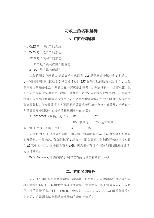
功放上的名称解释一、正面名词解释一、GAIN是“增益”的意思;二、BASS是“低音”的意思;三、ECHO是“混响”的意思;1、RPT是“混响次数”的意思2、DLY是“混响延迟”比如你用麦克风说1.然后音响出现回音,DLY就是回音中第一个1和第二个1中间的间隔时间(比如0.3秒或0.5秒),RPT就是可以调后面出现几个1(比如是重复五次还是七次).两者合在一起就是混响效果。
调试没有一个固定标准,我们常见的就是KTV里面的,混响一般开的比较大,因为混响效果可以让不是太会唱歌的人唱出来的歌缺陷没那么大,也就是会掩盖缺陷,另一方面有一些混响唱歌会显轻松。
但专业歌手大多不用混响效果或者只加一点点空间效果,当然有一些歌曲需要个别语句加混响效果达到整体的完美!3、SELECTOR(切换开关): MO , STMO:单声道; ST:是立体声。
四、SELECTOR(切换开关): A , B;后面板的A、B是可以分别接2组音箱,知前面板的A、B是切换这2组音箱的开关道,一般来说,你如果接了2组音箱,那么面板上的切换开关应该设专置为AB其中的一组,而不能设置为A+B,因为那样有可能因为负载的阻属抗过低而损坏功放;BAL:balance,平衡的简写;调节左右两边的音箱声音一样大。
二、背面名词解释五、PRE OUT指的是音频输出(前级输出的意思)。
音频输出经过功放机前机的音频处理,它可以用于连接耳机或者其它音响设备,比如录音设备,可以把用户唱的歌录下来。
备注:PRE OUT全名是Preamplifier Output就是前级输出的意思,它是用来输出驱动音响震动发出的声音的。
六、白色接头传输左声道音频信号,红色接头传输右声道音频信号,黄色接头传输视频信号。
(白红黄-左右视)。
DELCOS3100智能控制器操作手册
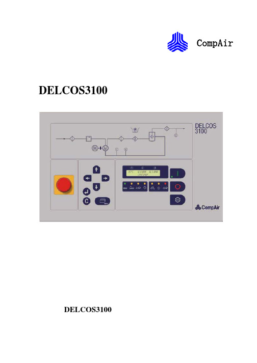
CompAir DELCOS3100控制器DELCOS3100操作指南2DELCOS 3100 控制器目录1.1 操作元件 41.1.1 键盘 41.1.2 发光二极管 51.1.3 语言选择 61.1.4 空白文本区——第1行 61.1.5 空白文本区——第2行状态显示 61.2 DELCOS 3100菜单结构示例81.2.1 菜单[保养时间安排] 91.2.2 菜单[控制菜单] 91.2.3 菜单[故障存储器] 91.2.4 菜单[极限值] 101.2.5 菜单[可选输入项] 101.2.6 菜单[定时器控制]选项 101.2.7 数值的修改121.2.8 密码的锁定和解锁定121.2.9 设置密码131.3 调试131.3.1 机器的起动131.3.2 加载和空载运行的操作141.3.3 关机141.3.4 失灵跳闸和电源故障141.3.5 警告141.3.6保养 141.3.7 汇集型故障继电器141.3.8运行/加载计时器141.3.9故障存储器 151.4 发生故障或警告时DELCOS 3100故障表161.4.1 检查项目表161.4.2 故障/警告表 161.5 保养时间间隔201.6 操作方式201.6.1 自动和连续运行201.6.2 远程控制机器的开和关201.6.3 远程控制加载和卸载211.6.4 远程控制加载方式可行211.6.5 发生电源故障后的自动重新起动221.6.6 发生电源故障后无限制自动重新起动231.6.7 RS485通讯 231.7 出厂前设定的极限值233DELCOS 3100控制器图11.1 操作元件1.1.1 键盘I键 => 起动系统O键 => 关闭系统键 => 确定键=>在菜单中时中断输入方式恢复先前的数值空白文本区 => 第1行最终温度/最终压缩压力/总管压力的指示=>第2行状态显示运行方式菜单键MENU=>打开和关闭菜单C键 =>输入存取代码用于保护各种菜单项键 =>在菜单中时向上滚动在输入方式时更改参数键 =>在菜单中时向下滚动在输入方式时更改参数键 =>在菜单中左移一列键 =>在菜单中右移一列↵键 =>输入值要被更改或确定4DELCOS 3100控制器图21.1.2 发光二极管 运行信息 LED a=>闪动系统处在待命方式即马达随时都会自动起动 亮着驱动马达在运行LED b=> 操作者在操作菜单LED c=>自动重新起动切换在ON接通位置LED d => 闪动远程控制处在远程关闭亮着远程控制处在远程接通可选项 LED e=>闪动在定时控制方式中为压缩机关闭 亮着在定时控制方式中为压缩机已起动信息 LED f => 保养期限已到 LED g => 警告 LED h=>汇集型故障如果LED f LED g 或LED h 点亮在空白文本区就会显示信息应按以下章节 1.3.4至1.3.9所述的方法确定故障警告或要求保养的原因5DELCOS 3100 控制器1.1.3 语言选择DELCOS 3100备有17种语言同时按↵键和Θ键就从一种语言切换到另一种语言为使在国际中范围内通用在切换中将显示国家的代号说明进入菜单状态时不能切换语言当LED b=>OFF 时在英语显示时可更改单位,Bar 或℉,PSI.1.1.4 空白文本区——第1行在正常的运行条件下空白文本区的第1行中应显示下列的系统参数值1 => 最终温度 传感器R2 2 => 最终压缩压力 传感器B23 => 总管压力传感器B1万一某个传感器发生传输错误就无法确定和显示实际的参数值显示区就显示并在第2行中会相应显示传感器故障FAULTSENSOR最终温度显示显示的值指示最终的压缩温度 如果温度太高温度显示会发生闪烁最终压缩压力显示显示的值指示最终的压缩压力参见上述内容如果系统的压力或最终的压缩压力太高显示内容会发生闪烁参见上述内容总管压力显示显示的值指示总管的实际压力1.1.5 空白文本区——第2行状态显示空白文本区的第2行显示的是机器有关的状态发生故障时该显示信息可被永久性重写而出现警告或保养要求时可被周期性重写下面列出的状态显示信息具有以下意义可以起动READY TO START机器已可以起动但尚未起动警告起动要有WARNING START WITH与压力要求PRESSURE REQUIREMENT交替显示机器已经起动待命状态但没有压力要求警告起动需先WARNING START AFTER与释放压力DE-PRESSURISE交替显示 机器已经起动待命状态但最终压缩压力仍高于起动保护值 警告起动要有WARNING START WITH与 定时器控制TIMER CONTROL交替显示机器已在可选的定时器控制运行方式下起动待命状态但尚未收到定时器的激活信号警告起动采用WARNING START BY与 远程操作REMOTE OPERATION交替显示启动了远程控制运行方式需要用远程开机REMOTE ON 信号起动6DELCOS 3100 控制器 警告xxS 后起动WARNING START IN xxS与 因断电AFTER POWER LOSS交替显示发生电源故障后由于自动重新起动功能要在xx 秒延时后重新起动 马达起动阶段MOTOR START PHASE马达在起动 空载OFF-LOAD机器以空载方式运行 负载ON-LOAD机器进行负载运行 软停机时间xxSSOFT STOP xxs机器已关闭过xx 秒后将停机 续运行定时器yySRUN ON TIMER yys机器处于续运行阶段 故障<故障信息>FAULT <故障信息> 因故障而停机 警告<警告信息>WARNING<警告信息>如果出现警告信息状态文字会显示3秒说明有关故障和警告信息的解释请参看故障存储器表1.4保养期限已到MAINTENANCE ELAPSED如果保养期限已到通常不是像出现故障时那样把状态文字重写掉而是每12秒钟显示3秒钟附加的信息说明有关各种保养期限的说明请参看1.5节7DELCOS 3100 控制器1.2 DELCOS 3100菜单结构示例保养时间安排[MAINTENANCE SCHED.] 控制菜单[CONTROL MENU] 故障信息存储[FAULT MEMORY]总运行时间TOTAL RUNNING 加载时间LOADED HOURS空气过滤器再经AIR FILTER IN油过滤器再经OIL FILTER IN油分离器再经SEPARATOR IN换油再经OILE CHANGE IN 电机加油脂再经MOTOR GREASING 未激活停机功能SHUTDOWN DEACTIVETED 12435h10987hh9999 h0 h-385 h-9999 h切断点CUT-OUT POINT切入点CUT-IN POINT自动运行方式AUTOMATICOPERTATION远程控制REMOTE CONTROL定时器控制TIMER CONTROL自动重新起动AUTO RESTART断电时间POWER LOSS TIME起动延时START-UP DELAYRS485协议RS485 PROTOCALRS485传输波特率RS485 BAUD RATE从动机号码NUMBER OF SLA VE*可选项13.0bar/188PSI12.5bar/181PSI开ON关闭OFF*关闭OFF1.5 秒60 秒ModBus19200112 外部故障12! EXT FAULT2压缩机温度2! COMP TEMP4温度过高4! HIGH TEMP18紧急停机18! EM-STOP6马达温度6! MOTOR TEMP5马达温度5! MOTOR TEMP2传感器B22! SENSOR B210压力过高10! OVER PRESS11438 h9877 h9476 h4867 h4310 h4310 h88 h17 h[定时器控制]*可选{TIMER CONTROL} *OPTION [限制值] [LIMIT V ALUES] [可选的输入参数][OPTIONAL INPUTS]周几日期时间SA 29.01.94 13:55:141 00:00 00:002 00:00 00:003 00:00 00:004 00:00 00:005 00:00 00:006 00:00 00:007 00:00 00:00减低00:00 00:00 REDUCE 减低量0.0bar/0psi REDUCE BY*仅用于定时器组件配备可选设计压力DESIGN PRESS起动保护START PROTECT最终温度警告FINAL TEMP WARN最高的最终温度FINAL TEMP MAX最低起动温度MIN START TEMP续运行时间RUN-ON TIME软关机SOFT STOP星/三角时间STAR/DELTA TIME软件SOFTWARE13bar/188psi0.8bar/11psi110/230F120/248F1/34F360 秒30 秒8 秒SD31V1.00可选项 1OPTION 1可选项 2OPTION 2可选项 3OPTION 3排气温度DISCH TEMP外部故障EXT FAULT空闲FREE8DELCOS 3100 控制器1.2 DELCOS 3100菜单结构菜单显示参见空白文本区的第二行要进入各菜单项时按[菜单]Menu键用向左和向右键可在各子菜单之间切换在各子菜单中可用向上和向下键调出各种参数菜单在水平方向或垂直方向上都不能滚动即它们是受限的改变参数前可能需先输入一密码具体可参看1.2.8节最后一次键操作后过两分钟菜单会自动退出下列1.2.1点至1.2.6点的各显示值和第8页上的表格仅作为例子危险如果当机器处于待命方式时作参数调整则机器随时可能起动1.2.1 菜单[保养时间安排]用和键可移动到菜单项[保养时间安排]MAINTENANCE SCHED.在该处可用和键调出各个参数下列参数输入值保存在菜单标题[MAINTENANCE SCHED.]下且可能会显示下列值总运行时间TOTAL RUNNING加载时间LOADED HOURS空气过滤器再经AIR FILTER IN油过滤器再经OIL FILTER IN油分离器再经SEPARATOR IN换油再经OILE CHANGE IN电机加油脂再经MOTOR GREASING停机功能SHUTDOWN12435h10987hh9999 h0 h-385 h-9999 h未激活DEACTIVETED说明具体信息可阅读1.5节[保养时间间隔]最后一次键操作后过两分钟菜单会自动退出1.2.2 菜单[控制菜单]用和键可移动到[控制菜单]CONTROLMENU在该处可用和键调出各个参数下列参数输入值保存在菜单标题[CONTROLMENU]下且可能会显示下列值切断点CUT-OUT POINT切入点CUT-IN POINT自动运行方式AUTOMATIC`OPERTATION远程控制REMOTE CONTROL定时器控制TIMER CONTROL自动重新起动AUTO RESTART断电时间POWER LOSS TIME起动延时START-UP DELAYRS485协议RS485 PROTOCALRS485传输波特率RS485 BAUD RATE从动机号码NUMBER OF SLA VE13.0 bar/188psi12.5 bar/181psi开ON关闭OFF关闭OFF1.5 秒60 秒ModBus192001说明具体信息可阅读1.6节[操作方式]最后一次键操作后过两分钟菜单会自动退出1.2.3 菜单[故障存储]用和键可移动到[故障存储]菜单FAULTMEMORY在该处可用和键调出各个参数故障信息按如下方式保存在故障存储[FAULTMEMORY]中12 外部故障12! EXT FAULT2压缩机温度2! COMP TEMP4温度过高4! HIGH TEMP18紧急停机18! EM-STOP6马达温度6! MOTOR TEMP5马达温度5! MOTOR TEMP2传感器B22! SENSOR B210压力过高10! OVER PRESS11438 h9877 h9476 h4867 h4310 h4310 h88 h17 h跳闸故障用标记而警告则不显示说明具体信息可阅读1.3.9节[故障存储](FAULT MEMORY)最后一次键操作后过两分钟菜单会自动退出9DELCOS 3100 控制器1.2.4 菜单[极限值]用和键可移动到[极限值]菜单LIMITV ALUES 在该处可用和键调出各个参数例如下列参数的输入值是储存在菜单标题[限制值]下的设计压力 DESIGN PRESS 起动保护 START PROTECT最终温度警告FINAL TEMP WARN 最高的最终温度FINAL TEMP MAX最低起动温度MIN START TEMP 续运行时间RUN-ON TIME 软关机SOFT STOP 星/三角时间STAR/DELTA TIME 软件SOFTWARE: 13.0bar/188psi 0 .8bar/11psi 110/230F120/248F 1360秒 30秒8秒SD31V1.00说明操作者不能改变出厂前设定的极限值也可参阅1.2 8.)最后一次键操作后过两分钟菜单会自动退出1.2.5 菜单[可选输入项]菜单标题[可选输入项]以可选软件的形式提供可以选择性安装各个附加的监测元件用和键可移动到[可选输入项]菜单OPTIONAL INPUTS 在该处可对三个保留输入项进行分配只须指出哪个监测功能被分配给了哪个输入项标记为[空闲]的输入项没有激活/监测可用和键调出各个参数对每一项输入可从下列表中选择一项分配值选择适用判据油压OIL PRESS 故障 油位OIL LEVEL 警告 外部故障EXT FAULT 故障 排气温度DISCH TEMP 油温OIL TEMP 警告 警告 转子/皮带ROT/BELTS 故障 操作—B1 OPERATE-B1 参阅1.6.3节 空闲 FREE无操作例输入input1 排气温度DISCH TEMP 输入input2 外部故障EXT FAULT 输入input3空闲FREE最后一次键操作后过两分钟菜单会自动退出1.2.6 菜单[定时器控制]可选项 (TIMER CONTROL) 危险在待命方式下进行编程时机器随时可能会起动若安装了实时时钟可使用定时器控制来开关机器此外可对某些时间段预设置压力减小量例如夜间的压力减小未要求定时器控制时[定时器控制关闭]TIMER CONTROL OFF压力减小也可处于激活状态如果要通过定时器控制来开关机器必须在[控制菜单]中激活[打开定时器控制]需要时还要将机器运转起来开机(SWITCH ON)要设置定时器控制或压力减小量用和键移动到菜单项[定时器控制](TIMER CONTROL)然后用和键调出各个参数基本的时钟设定例[周六 29.01.94 13:55:14] 按[↵]键周几[SA]会闪烁 用和键重新设置周几 按[↵]键确认新设置值这时日期会闪烁[29] 用和键重新设置日期按[↵]键确认新设置值设置月份年份钟点分钟和秒钟的方法与上述方法相同当用[↵]键确认秒钟的新设置值后时钟就会按该新的设定值行走任何时候按[Θ]键就可中止时钟的设置步骤10时钟定时器的设定共提供了7个时钟定时器块 例2号块未激活[2_________00:00 00:00]例1号块星期一至星期五开机每日从07:30至16:15[1__MTWTF__07:30 16:15] 用和键选择了定时器时钟块后例[1_________00:00 00:00]按[↵]键周几会闪烁Sunday用和键选择所需的设置值按[↵]键确认新设置值这时周几的下一天会闪烁Monday用和键选择所需的设置值按[↵]键确认新设置值重复上述步骤设置一周其它的日子以及各天起动和关闭的所需时间任何时候按[Θ]键就可中止时钟的设置步骤这时就恢复先前的设置例1工作时间为从周日22:00至周六14:00每日中断时间为从12:00至12:30 时钟定时器的设置应为[1S________ 22:00 24:00] [2_MTWTFS 00:00 12:00] [3_MTWTF_ 12:30 24:00] [4_______S 12:30 14:00] [5________ 00:00 00:00] [6________ 00:00 00:00] [7________ 00:00 00:00]例2从周一6:00至周五22:00 需要有连续的压缩空气供应[1_M_______ 06:00 24:00] [2__TWT___ 00:00 24:00][3_____F____ 00:00 22:00] [4__________ 00:00 00:00][5__________ 00:00 00:00] [6__________ 00:00 00:00][7__________ 00:00 00:00]峰外压力减小的设置所需的峰外压力减小应分两步设置减小压力与时钟定时器的设置无关[减小(REDUCE) 22:00 06:00] [减小量(EDUCE BY) 1.5 bar] 在上述例子中总管压力在22:00到6:00间会减小1.5巴例如如果在[控制菜单]中预设总管压力介于 [切入点9.0 bar]和[切断点10.0 bar] 则在夜间总管压力会减小到7.5和8.5 bar即使在峰外压力减小期间[控制菜单]中显示的[切入点]]和[切断点]的值不会改变峰外减小的时间和峰外压力的设置方法与设置时钟定时器的方法相同如果不想有峰外减小可设置为[减小 00:00 00:00]和/或 [减小量 0.0 bar] 最后一次键操作后过两分钟菜单会自动退出1.2.7 数值的修改 危险在待命方式下进行编程时机器随时可能会起动如果密码处解锁定状态参阅1.2..8节则可在任意时候修改除[极限值]外的任意值用和键可移动到要更改的值按[↵]键以进入输入模式若密码尚未解锁定则会向你询问密码当输入模式激活后显示的数值会闪烁说明在输入模式和键无效 用和键输入新的值后必须按[↵]键对新值进行确认这时显示会停止闪烁并可选择新的子菜单项了在输入模式时如按[Θ]键可恢复原先的设置值并退出输入模式1.2.8 密码的锁定和解锁定为避免非授权编程可用密码来保护设置值操作者不能更改出厂前设定的极限值锁定如果要锁定密码可按[C]键这时会显示下列信息 CODEUNLOCK密码解锁定显示约1秒CODE INPUT 0000输入密码数值闪烁 如果输入密码[3031]就会显示下列信息CODE LOCK 密码锁定显示约1秒如果密码输入错误则会显示下列信息CODE UNLOCK 密码解锁定显示约1秒然后程序自动返回起始点解锁定用下列操作可重新将密码解锁定按[C]键或按[↵]键并试图更改某个被保护的数值这时会显示密码询问CODE LOCK 密码锁定显示约1秒CODE INPUT 0000输入密码 数值闪烁你必须输入密码[3031]如果密码输入正确则会显示下列信息 CODE UNLOCK 密码解锁定显示约1秒如果密码输入错误则会显示下列信息CODE LOCK 密码锁定显示约1秒然后程序自动返回起始点说明如果密码不自动锁定操作者可决定是否要实现该功能1.2.9 设置密码 设置-DELCOS 3100密码10001A.-Nr 12345678 密码20001Fab.-Nr. 123456/1234 密码30001 RA/XY/291194/CSD3-V01COMPAIR Drucklufttechnik 标贴设置密码说明设置密码放于开关箱内若DELCOS 3100控制器发生过故障或进行过更换控制部分会要求你输入三个设置密码空白文本区会显示CompAirSETUP-CODE 1:_______ 这时按和键输入正确的密码再按[↵]键确认然后会自动显示CODE 2密码2像输入密码1一样进行操作按[↵]键对密码2确认后又会自动显示密码3再像操作密码1和密码2一样进行如果密码输入出错系统会自动要求你重新输入密码1即需重新输入所有密码如果所有密码都输入正确机器将自动复位到其基本设置值重要下次起动前应检查DELCOS 3100的所有设置值并恢复各设置值这一点很重要尤其在[可选的输入参数]菜单那些连接是可选的监测器都必须按电路图重新进行定义否则就不提供监测功能参阅1.2.5节1.3 调试 危险若系统处于待命运行方式即LED a 在闪烁则压缩机随时可能自动起动1.3.1 机器的起动接通电源后会显示LED 测试应按[Θ]键对此确认后再起动机器按[I]键使机器运行前须纠正所有故障情况并予以确认温度低于允许的起动温度时参阅1.2.4节[限制值]压缩机不能起动若起动时压缩空气总管没有用气需求机器会进入待命方式LED a 会闪烁空白文本区显示[WARNING START WITH]和相关的信息参阅1.1.5节状态显示另外有一安全回路起动保护可防止马达在有内部残余压力时起动在这种情况下压缩机也进入待命方式压力降至出厂前设置的起动值以下或压缩空气总管有用气需求时压缩机会自动起动按[I]键或由远程控制发来一个开启脉冲可激发出起动询问检查马达是否具备可起动条件如果下列起动条件中有一个不满足机器在该时刻就会进入待命状态ON 键会闪烁最终压缩压力高于起动保护值 各总管都无用气需求仅适用于自动运行方式时钟定时器发来了激活信号仅适用于已进入定时器控制情况** 可选项1.3.2 加载和空载运行的操作 危险若系统处于待命方式即LED a 在闪烁机器随时可能会起动出厂前是将机器设为自动运行的这就是说压缩机是根据用气的情况来提供压缩空气和停机待命的若在一段时间内压缩空气总管的用气量很低甚至不用气机器就会自动转换到空载运行方式在空载运行阶段冷却通风/冷却水会根据温度情况自动关闭当续运行阶段在自动运行方式下空载运行已过马达会在用完预设的续运行时间后关闭压缩机转换到待命方式剩余的[续运行时间]会显示在空白文本区内1.3.3 关机按O 键后会出现30秒[软关机]时间然后马达关闭1.3.4 失灵跳闸和电源故障 为保护机器一旦发现可辨认的故障都会立即将系统跳闸或不让机器起动空白文本区中会显示这些故障LED h 将点亮这些信息会转送到故障存储器然后向汇集型故障继电器发出信号这些故障必须按[Θ]键确认在故障纠正后若发生[断电]则电压一旦恢复马上出现LED 测试必须在机器就地按[Θ]键对它进行确认但是采用远程控制运行方式时发一个远程打开脉冲就足以给[故障存储器]送出确认信号了1.3.5 警告有警告信息时通过LED g 发出信号同时在空白文本区中显示警告的性质警告信息不会使机器跳闸但会传送到故障存储器若不处理警告信息可能会造成失灵1.3.6保养有保养信息时通过LED f 发出信号保养信息会传送到故障存储器若保养期已满即已到了0小时空白文本区会显示信息[保养期已满]已过的这段保养期时间长度可通过[保养时间安排]来确定参阅 1.2.1若不遵守保养期限可能会造成失灵参阅1.5节保养时间间隔1.3.7 汇集型故障继电器控制器中有一个无源触点参阅电路图会发出机器的失灵信号汇集型故障继电器的无源触点的负载不可超过250V/1A1.3.8运行/加载计时器可随时调看机器的运行时数和负载时数 要调看时选择[保养时间安排]菜单选择其中的[运行总时数](TOTA RUNNING)或[负载时数](LOADED HOURS)参阅1.2.1节就可查阅当前的状态了说明若更换DELCOS 3100的控制器则运行时数和负载时数都会丢失1.3.9故障存储器故障存储器中存储着次数故障/警告文字和发生故障警告时计得的总时数要查阅时按1.2.3节的指南选择[故障存储器]菜单发生故障/警告且又未被确认时当前故障/警告的次数会闪烁一般故障即跳闸是用一个加以标记而对警告则不显示例例如12! MOTOR TEMP 12345h.解释* 12的意义同一故障已发生12次*MOTOR TEMP 故障是指马达温度*12345h 最近的故障是在运行了12345运行时数后出现的显示中只含8个最新的信息其中最近的在列表的顶部由于故障存储器的显示空间限于8个表项更早的表项不能显示而是与它们相应的次数一起存储在长期的存储器中这就意味着若又发生了某个故障/警告有关的故障/警告信息会与该故障/警告的当前次数及重发生该故障/警告时的时数一起显示出来DELCOS 3100 控制器1.4 发生故障或警告时DELCOS 3100故障表1.4.1 检查项目表一般来说接头和插头的松动电源有问题或未遵从安装指南等均会造成各种故障因此常常可从显示的故障信息中追踪到不同的原因为此请用户始终遵从下列检查表1. 机器的电源电压须在允许的限度内2. 需要时须把控制电源变压器调整到能适合当地的额定电压参阅电路图3. 开关箱的温度不可超过554. 如无耦合中继器加装的远程控制线远程开/关远程加载/卸载距开关箱的长度不可超过20米5. 在调试和保养时要检查所有接头螺钉是否旋紧所有接头是否连接良好6. 电源线须有足够大的截面因此在选择电源线时须考虑到安装的要求电线的长度及预计的护套管温度7. 加装开关设备时无论如何也不能在电源控制变压器上抽头因为这样做会造成过载8. 始终要使用CompAir 备件9. 未事先征得CompAir 的同意勿另连接开关或测量设备10. 决不可将测量传感器从机器上移开11. 若要进行咨询请持有如下信息从而使我们能提供快速具体的支持-机器类型/系统编号-订单编号-电路图号和零件号-有关机器运行情况的信息-有关你方自己加装的附件远程控制等的信息-此后对机器的其他修改和附件-对故障准确的描述1.4.2 故障/警告表在以后各页中您将可看到DELCOS 3100故障表并附有可能的原因和纠正措施[显示]/问题可能的原因纠正措施[FAULT POWER LOSS] [停电故障] 电源故障电压下降电线有毛病接头掉落/松动查找原因查找原因检查需要时加以修理检查所有的连线的接头和连接器是否连接合适需要时将它们重新加紧[FAULT EM-STOP] [故障紧急停机] 紧急停机已激活紧急停机开关有毛病电线有毛病解除锁定检查需要时更换检查需要时加以修理[FAULT MOTOR TEMP] [故障马达温度] 马达起动过于频繁马达冷却不充分用电需求过高电源有毛病马达有缺陷星/三角开关有毛病限制每小时的起动数改进检查寻找原因检查寻找原因检查需要时更换检查需要时加以修理[FAULT COMP TEMP][故障压缩机温度]超过了最终的压缩温度1[WARNING HIGH TEMP] [警告温度过高] -进气温度过高-冷却不充分-机器运行时进入门板打开着-注油量/注油温度不充分/过度-油/粘度类型不正确-温度传感器 R2有毛病温度显示过高改进改进关闭进入门板检查寻找原因检查需要时更换用油检查需要时更换[FAULT START TEMP] [故障起动温度] 试图在温度太低的情况下起动(1)-温度传感器 R2有毛病温度显示过高给压缩机房加温检查需要时更换[WARNING HIGH PRESS][警告压力太高]运行压力超过了1.0巴(1)[FAULT OVER PRESS] [故障压力过高] 运行压力超过了1.5巴(1)-在机器中压力损耗过大-总管的压力切换点(4)太高-外部压力需求过高-进气调节器未关闭-压力传感器B1或B2有毛病显示错误检查寻找原因纠正检查远程加载/卸载切换点检查寻找原因检查需要时更换[FAULT SENSOR B1][故障传感器 B1]总管压力传感器有毛病[FAULT SENSOR B2][故障传感器 B2]最终压缩压力传感器有毛病[FAULT SENSOR R2] [故障传感器 R2] 最终压缩温度传感器有毛病-压力或温度传感器有毛病-连接传感器的电线有毛病检查需要时更换检查需要时修理[显示]/问题可能的原因纠正措施[FAULT DIRECT ROT] [故障 转动方向] 驱动马达转动方向错误参阅电路图将各相顺序正确连接[FAULT MAINT PER] [故障 保养期满] 激活了跳闸保养功能(2)保养期限超过了100小时(2)进行保养并重新设定期限[FAULT SOLENOID] [故障 电磁阀] 接电磁阀Y1或Y4的电路短路或断路 检查需要时修理或更换 [FAULT COOLING] [故障 冷却]空冷型机器机器风扇故障-通过进气/排气通道的阻力太大 -风扇马达保护开关的设置错误 -风扇马达有毛病 水冷型机器冷却水量不足 -冷却水温度过高 -冷却水流不足 -过滤器阻塞 -冷却水电磁阀未打开 -系统中有空气检查需要时安装辅助风扇 将额定风扇流量设到110% 检查需要时更换 改进 增加 清洁 检查需要时更换 泄放 [FAULT DRIVE BELT] [故障 驱动皮带]可选V 型皮带失效/撕坏 通过输入监测转向/皮带(3)检查需要时更换[FAULT OIL PRESS] [故障 油压]可选无油压或油压不足 通过输入监测油压(3)检查寻找原因[FAULT EXT FAULT] [故障 外部故障]可选外部故障造成的跳闸 通过输入监测外部故障(3)检查寻找原因 [FAULT ELECTRONIC] [故障 电子线路]DELCOS 的硬件故障更换DELCOS 电子线路[WARNING SEPARATOR] [警告 油气分离器]可选 油/气分离器芯压差过大 检查需要时更换油/气分离器芯[WARNING AIR FILTER] [警告 空气滤清器]可选 空气滤清器压差过大 检查需要时更换空气滤清器[WARNING OIL FILTER] [警告 油过滤器]可选 油过滤器压差过大 检查需要时更换油过滤器[WARNING OIL TEMP] [警告 油温]可选注油温度过高 通过输入监测油温(3)检查寻找原因[WARNING DISCH TEMP] [警告 排气温度]可选压缩空气排气温度过高 通过输入监测排气温度(3)检查寻找原因[WARNING OIL LEVEL] [警告 油位]可选油位太低 通过输入监测油位(3) 检查需要时加满油。
PC3100简体中文操作手
键回到测量模式。 注二:做单点校正时仅调校零点 OS 值,未修改斜 率 SLP 值,仪器沿用上次校正后储存的斜率值。
3. 校正成功时,屏幕出现 CAL PASS 字样,校 正失败时,出现 CAL Err 讯息。(请参阅第十 章错误讯息,寻求原因及处理方法)
4. 屏幕将自动显示校正之 OS (零点电位)值, 按 键显示校正之 SLP (斜率) 值,再 按 键回至测量模式。
2.1 主机固定:本变送器可盘面式、2 吋管式、壁挂式安装 盘面式安装:请预先在配电箱面板上留一 138 x 138mm 的方孔,变送器从配电箱之面板直接放 入,将变送器所附之固定架由后方套入,卡进固定槽内。 2.2 盘面式安装参考图:
138mm
138mm
挖孔尺寸
固定器
+
42mm 42mm
+ +
+
盘面安装方式,使用盘 面固定器固定
Байду номын сангаас
恢复原厂默认值
按 + 键五秒后,再按 键,出现 后,即恢复原厂参数默认值
按
+
键五秒后,再按
键,出现
后,即恢复原厂校正默认值
4
一、 规格
机型 测试项目 测 试 范 围 解 析 度 精 确 度 pH ORP TEMP pH ORP TEMP pH ORP TEMP PC-3100 pH/ORP/TEMP -2.00~16.00pH -1999~1999mV -30.0~130.0C 0.01pH 1mV 0.1C ±0.01± 1 Digit ±0.1% ± 1 Digit ±0.2C± 1 Digit 具温度误差修正功能 NTC30K/ PT1000 自动温度补偿 手动温度补偿 自定义单双点校正及预设 Tech & 自定义单双点校正及预设 Tech、 NIST 标准液两点自动校正 NIST 标准液两点或三点自动校正 0~50C -20~70C > 1012 Ω 背光式大型液晶显示,具背光感应器做自动及手动背光选择 隔离式 0/4~20mA 可设定对应 pH/ORP 量测范围,最大负载 500 隔离式 0/4~20mA 可设定对应温度 量测范围,最大负载 500 - HI/LO 两组独立之控制点 接点输出,ON 0~9999 秒 / OFF 0~999.9 小时 DC±12V IP65 100V~240VAC±10%,50/60Hz 壁挂式/管路式/盘面式 144 mm 144 mm 115 mm (HWD) 138 mm 138 mm (HW) 0.8Kg
NOVAWin 手册

V. 1.12 USER MANUAL
Part Number 05079 Rev A
NOVA Series Windows-Based Operating and Data Analysis Software
© Quantachrome Instruments, 2002
QUANTACHROME WARRANTY POLICY
NOVAWin User Manual Ver. 1.11
2
TABLE OF CONTENTS
A. B. SAFETY........................................................................................................................................................ 5 INSTALLATION......................................................................................................................................... 8 User Disk ........................................................................................................................................................8 Program (Upgrade/Installation) Disk..............................................................................................................8 NOVAWin Program Disks ..............................................................................................................................8 C. 1. 2. 3. INSTRUCTIONS FOR USE ....................................................................................................................... 9 CALIBRATE MANIFOLD VOLUME .....................................................................................................9 CALIBRATE SAMPLE CELL................................................................................................................10 SAMPLE PREPARATION .....................................................................................................................10 Methods of Sample Preparation....................................................................................................................10 Choice of Degas Temperature and Degassing Time .....................................................................................12 Elutriation and Its Prevention .......................................................................................................................13 Unloading the Degasser ................................................................................................................................14 4. SETUP ANALYSIS.................................................................................................................................15 5. ANALYZE SAMPLE ..............................................................................................................................15 6. DATA ANALYSIS AND REPORT GENERATION .............................................................................16 D. 1. SAMPLE MEASUREMENT .................................................................................................................... 17 CELL CALIBRATIONS .........................................................................................................................19 Cell Calibrations: Argon ...............................................................................................................................20 Cell Calibrations: Carbon Dioxide and N-Butane.........................................................................................21 Cell Calibrations with Other Adsorbates (User Defined Adsorbate) ............................................................22 Printing Cell Calibration Data Files..............................................................................................................23 2. SETUP PARAMETERS AND RUN ANALYSIS ..................................................................................24 Analysis Setup – Common............................................................................................................................25 Analysis Setup – Stations..............................................................................................................................27
N300R说明书
3)如果上网方式为PPPOE,如下图所示,输入运营商提供给你的用户名、用
户密码、MTU值(默认值为1492如非特殊情况请勿更改)。并提供了PPPOE上网时
间控制功能,方便用户家长式的管理。
4.1.3 无线基本设置
当点击“基本设置”即可以做基本的无线通讯设置。如下图:
1、选择WEP,点击“下一步”,如下图所示:
选择密码的长度,点击“下一步”,如下图所示:
用户选择使用64字节的密码长度,输入5位的十六进制密码,选择使用128字节
的密码长度则输入13位的十六进制密码。点击“下一步”,如下图所示:
确定配置无误,点击结束,无线部分已经配置完成了。
2.2硬件安装步骤
1. 将ipTIME N300R的电源接通。
2. 将路由器的WAN口用网线连接至xDSL Modem/Cable Modem或小区提供的宽
带接口。
3. 若要进行有线连接,用双绞线将计算机与路由器的LAN口连接。
4. 若要进行无线连接,请检查您的无线网卡是否启用。若没有请启用无线网
浏览器将进入路由器设置页面,如下图所示:
点击广域网设置向导菜单进入安装向导界面,如下图所示:
用户可选择自动和手动两种网络配置,这里介绍手动网络配置。
选择手动网络配置,点击“下一步,如下图所示:
广域网连接类型:本路由器支持三种常用的上网方式,请您根据自身情况进
2、选择WPAPSK加密方式,点击“下一步,如下图所示:
选择密码系统,点击“下一步”,如下图所示:
输入8位以上的密码,点击“下一步”,如下图所示:
确定配置无误,点击结束,无线部分配置完成。
NETGEAR ReadyNAS 3100 安装指南说明书
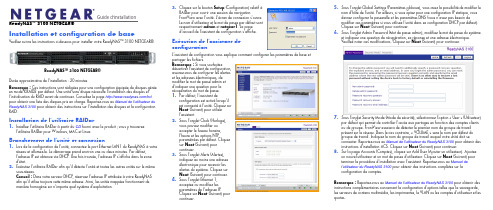
Guide d'installationReadyNAS™ 3100 NETGEAR®Installation et configuration de baseVeuillez suivre les instructions ci-dessous pour installer votre ReadyNAS™ 3100 NETGEAR®.Durée approximative de l'installation : 20 minutes.Remarque : Ces instructions sont rédigées pour une configuration équipée de disques gérée en mode X-RAID2 par défaut. Une unité sans disque nécessite l'installation des disques et l'initialisation du RAID avant de continuer. Consultez la page /hcl pour obtenir une liste des disques pris en charge. Reportez-vous au Manuel de l'utilisateur du ReadyNAS 3100 pour obtenir des instructions sur l'installation des disques et la configuration RAID.Installation de l'utilitaire RAIDar1. Installez l'utilitaire RAIDar à partir du CD fourni avec le produit ; vous y trouverezl'utilitaire RAIDar pour Windows, MAC et Linux.Branchement de l'unité et connexion1. Lors de la configuration de l'unité, connectez le port Ethernet LAN1 du ReadyNAS à votreréseau et allumez-le. Le démarrage prend environ une ou deux minutes. Par défaut, l'adresse IP est obtenue via DHCP . Une fois trouvée, l'adresse IP s'affiche dans la zone d'état.2. Exécutez l'utilitaire RAIDar afin qu'il détecte l'unité et toutes les autres unités sur le mêmesous-réseau.Conseil : Dans votre serveur DHCP , réservez l'adresse IP attribuée à votre ReadyNAS afin qu'il utilise toujours cette même adresse. Ainsi, les unités mappées fonctionnent de manière homogène sur n'importe quel système d'exploitation.ReadyNAS™ 3100 NETGEAR®3. Cliquez sur le bouton Setup (Configuration) relatif à RAIDar pour ouvrir une session de navigationFrontView avec l'unité. L'écran de connexion s'ouvre. Le nom d'utilisateur et le mot de passe par défaut sont respectivement admin et netgear1. La page d'accueil de l'assistant de configuration s'affiche.Exécution de l'assistant de configurationL'assistant de configuration vous explique comment configurer les paramètres de base et partager les fichiers.Remarque : Si vous souhaitezdésactiver l'assistant de configuration, assurez-vous de configurer les alertes et les adresses électroniques, de modifier le mot de passe admin et d'indiquer une question pour la récupération du mot de passe.1. Par défaut, l'assistant deconfiguration est activé lorsqu'il est connecté à l'unité. Cliquez sur Next (Suivant) pour utiliser l'assistant.2. Sous l'onglet Clock (Horloge),vous pouvez modifier ou accepter le fuseau horaire, l'heure et les options NTPparamétrées par défaut. Cliquez sur Next (Suivant) pour continuer.3. Sous l'onglet Alerts (Alertes),indiquez au moins une adresse électronique pour recevoir les alertes du système. Cliquez sur Next (Suivant) pour continuer.4. Sous l'onglet Ethernet 1,acceptez ou modifiez les paramètres de l'adresse IP .Cliquez sur Next (Suivant) pour continuer.5. Sous l'onglet Global Settings (Paramètres globaux), vous avez la possibilité de modifier lenom d'hôte de l'unité. Par ailleurs, si vous optez pour une configuration IP statique, vous devrez configurer la passerelle et les paramètres DNS (vous n'avez pas besoin demodifier ces paramètres si vous utilisez l'unité dans sa configuration DHCP par défaut). Cliquez sur Next (Suivant) pour continuer.6. Sous l'onglet Admin Password (Mot de passe admin), modifiez le mot de passe du systèmeet indiquez une question de récupération, sa réponse et une adresse électronique.Veuillez noter ces modifications. Cliquez sur Next (Suivant) pour continuer.7. Sous l'onglet Security Mode (Mode de sécurité), sélectionnez l'option « User » (Utilisateur)par défaut qui permet de contrôler l'accès aux partages en fonction des comptes clients ou de groupe. FrontView essaiera de détecter le premier nom de groupe de travail présent sur le réseau. Dans le cas contraire, « VOLUME » sera le nom par défaut du groupe de travail. Indiquez le nom du groupe de travail auquel votre unité doit seconnecter. Reportez-vous au Manuel de l'utilisateur du ReadyNAS 3100 pour obtenir des instructions d'installation ACS. Cliquez sur Next (Suivant) pour continuer.8. Sur la page Accounts (Comptes), cliquez sur Add User (Ajouter un utilisateur). Ajoutezun nouvel utilisateur et un mot de passe d'utilisateur. Cliquez sur Next (Suivant) pour terminer la procédure d'installation avec l'assistant. Reportez-vous au Manuel de l'utilisateur du ReadyNAS 3100 pour obtenir des instructions complètes sur la configuration de comptes. Remarque : Reportez-vous au Manuel de l'utilisateur du ReadyNAS 3100 pour obtenir des instructions complémentaires concernant la configuration d'options telles que la sauvegarde, les serveurs de contenu multimédia, les imprimantes, le VLAN ou les comptes d'utilisateur et les quotas.Février 2010Ce symbole a été apposé conformément à la directive européenne 2002/96 sur la mise au rebut des équipements électriques et électroniques (directive WEEE - Waste Electrical and Electronic Equipment). En cas de mise au rebut de ce produit dans un Etat membre de l'Union européenne, il doit être traité et recyclé conformément à cette directive.© 2010 par NETGEAR, Inc. Tous droits réservés. NETGEAR et le logo NETGEAR sont des marques déposées de NETGEAR, Inc. aux Etats-Unis et/ou dans d'autres pays. Les autres marques ou noms de produits sont des marques commerciales ou des marques déposées de leurs détenteurs respectifs. Ces informations sont susceptibles d'être modifiées sans préavis.Accès à votre stockage partagéVous remarquerez que ces protocoles de partage de fichiers sont activés par défaut : CIFS, AFP (annoncé sur Bonjour et ATP), HTTP/S. FTP , NFS et Rsync sont pris en charge mais ne sont pas activés par défaut.Reportez-vous au Manuel de l'utilisateur du ReadyNAS 3100 pour obtenir des instructions concernant l'accès aux partages à partir de système d'exploitation Linux ou Unix, le mappage de lecteurs et d'autres options de partage de fichiers, notamment la prise en charge d'un seul langage pour les noms de fichiers tels que ceux qui utilisent des caractères Unicode ou idéographiques.Accès aux partages à partir d'un ordinateur exploitant Windows1. Pour afficher une liste de partages sous Windows, cliquez sur Browse (Parcourir) dansRAIDar ou bien saisissez \\<adresse_ip> ou \\<nom_d'hôte> dans la barre d'adresse.2. Lorsque vous y serez invité, saisissez le nom d'utilisateur et le mot de passe pour vousconnecter au ReadyNAS. Windows Explorer affichera le contenu de partage duReadyNAS.Accès aux partages depuis MAC OS X1. Pour accéder au même partage sur AFP avec OS X, ouvrez Finder et recherchez un nomd'hôte ReadyNAS dans la section SHARED (PARTAGE). 2. Cliquez sur le nom d'hôte pour afficher les partages.Astuces et précautions d'emploiPour un fonctionnement optimal, suivez ces directives.•Mise sous/hors tensionLa mise sous tension de l'unité peut nécessiter environ une minute. Pour mettre l'unité hors tension, appuyez deux fois sur le bouton d'alimentation situé à l'avant de l'unité. Cette méthode permet une mise hors tension en bonne et due forme. Pour d'autres optionsconcernant la mise hors tension et le ralentissement de la rotation du disque, reportez-vous au Guide de l'utilisateur du ReadyNAS 3100.•VentilationQuatre disques haute vitesse et de grande capacité produisent une quantité de chaleur considérable. Veillez à ne jamais obstruer la grille de ventilation.•Utilisation d’une alimentation protégée (Onduleur avec batterie de secours)L’utilisation d’un onduleur protège votre unité et permet une mise hors-tension automatique en cas de coupure de courant. Pour en savoir plus sur l’utilisation d’un onduleur, consultez le Manuel de l'utilisateur du ReadyNAS 3100.•Affichage d'informations d'état dans FrontViewLa barre située en bas de l'utilitaire de configuration FrontView affiche des voyants d'état à code de couleurs permettant d'en savoir plus sur la connexion à des groupes de travail, les disques, le ventilateur, la température et l'ASI (le cas échéant). Double cliquez sur le voyant d'état pour afficher les détails correspondant à l'élément.•Redondance et extensionLe ReadyNAS 3100 est livré préconfiguré avec X-RAID2, afin de protéger vos données en cas de défaillance de disque unique tout en vous permettant d'accroître vos capacités à la volée. Pour augmenter votre capacité X-RAID, il vous suffit d'ajouter un nouveau disque avec une capacité égale ou supérieure au disque existant ; si les emplacements pour disques sont tous pleins, il est possible de remplacer les disques existants par des disques de plus grande capacité afin d'augmenter verticalement votre stockage. Les disques, qu'ils soient neufs ou de remplacement peuvent être ajoutés ou remplacés à chaud, un par un, en cours de fonctionnement du ReadyNAS. Il convient d'attendre que le nouveau disque soit complètement synchronisé avant de remplacer ou d'ajouter un autre disque. Utilisez FrontView pour savoir où en est le processus en cours ; par ailleurs, vous recevrez un message d'alerte pour vous indiquer que le processus de synchronisation est terminé.Assistance techniqueNous vous remercions d'avoir choisi les produits NETGEAR.Après l'installation de votre appareil, notez le numéro de série inscrit sur l'étiquette de votre produit. Il vous sera nécessaire pour enregistrer votre produit à l'adresse gear.fr/support/ Vous devez être enregistré pour utiliser notre service d'assistance téléphonique. Nous vous recommandons vivement de procéder à l'enregistrement sur notre site Web.Visitez le site gear.fr/support/ pour obtenir des mises à jour de produits et consulter le support Web.Pour en savoir plus sur l'installation, la configuration et l'utilisation de votre ReadyNAS™ 3100 NETGEAR®, reportez-vous au manuel de l'utilisateur du ReadyNAS 3100. Le CD qui vous a été livré avec l'unité contient un lien vers le manuel de l'utilisateur.。
ABI PRISM 3100 Genetic Analyzer

ABI P RISM 3100 Genetic Analyzer㆖機操作手冊I. 開機流程:1. 先開電腦及螢幕先開電腦及螢幕((user name 為”3100User ”, password 則空白不需輸入需輸入。
)。
)2. 按㆘3100 Genetic Analyzer 的電源鍵並確定機器㆖亮綠燈3. 檢查電腦螢幕左㆘方確定”OrbixWeb Daemon Software ”是否已經打開4. 打開3100 Data Collection software.(在桌面㆖應該可以找到Data Collection software 的捷徑的捷徑;若沒有;若沒有;若沒有,請到,請到Start menu 或依以㆘途徑尋找\D:\AppliedBio \3100\))II. 3100 裝置:㆖機裝置如㆘圖所示㆖機裝置如㆘圖所示,詳細步驟請參考以㆘流程,詳細步驟請參考以㆘流程:1. 將upper polymer block 裝到機器㆖裝到機器㆖,如㆘圖,如㆘圖,如㆘圖。
Upper polymer blockAnodebuffer reservoirU`pperPolymerblock2. 裝capillary array ,如㆘圖,如㆘圖。
(請從collection software 的”Tools ”㆘選擇Install Capillary Array Wizard ,以便輸入capillary array 的batch number )Array ferrule knoba. 將array loading header 的保護套拆㆘的保護套拆㆘。
將。
將loading header ㆖的pin 按入3100的固定點的固定點。
b. 將array ferrule knob 裝到polymer block ㆖,此時請勿鎖緊c. 將polymer block 稍微向外拉稍微向外拉,以方便裝,以方便裝capillary arrayd. 如㆘圖所示將capillary array ㆖array-ferrule end 及detection cell 之保護套卸㆘之保護套卸㆘。
ER3100说明书

1.10 如何设置端口限速和网络连接数,并查看端口/IP流量1. 每IP流量限制根据二八理论,即80%的带宽被20%的人占用来计算,而且占用的带宽大多为下行带宽,上行带宽一般选择下行带宽的一半或者2/3左右。
例如运营商带宽为10Mbps,带机量100台PC,80%的带宽就是8Mbps,20%的人就是20个人,那么8Mbps*1000=8000kbps(实际上应该乘以1024,这里简单以1000计算),8000kbps/20=400kbps,则理论值为每IP需要下行限速400kbps,上行值为200~300kbps,当然该计算值是理论值,需要根据实际的网络使用量来适当变化。
如果是ADSL宽带类型客户,则上行带宽建议限制为100kbps,且不推荐允许每IP通道借用空闲的带宽。
如果企业、酒店等环境,平时使用网络的时间或者占用的流量不是很大,那么可以适当将限速值调高,如下行600kbps,上行400kbps,并开启允许每IP通道借用空闲的带宽。
如网吧环境,带宽使用量较大,则需要增加带宽或者较少带机量来提高客户网速的体验,保证游戏和视频的正常工作。
网吧一般建议每IP限速下行800kbps,上行500kbps,开启弹性带宽功能,即允许每IP 通道借用空闲的带宽。
双WAN设备需要针对不同WAN口计算不同的限速值予以限制,最终主机获得的带宽为双WAN带宽限速总和。
2. 网络连接数一般建议每IP设置在1000~2000即可保证正常应用访问。
3. 查看端口/IP流量(1)查看每个物理端口流量:系统监控→流量监控→端口流量。
(2)查看局域网内各在线主机通过WAN口的流量:系统监控→流量监控→IP流量(3)实时查看WAN口流量:系统监控→流量监控→流量监视1.11 如何限制某些应用1. 限制某些游戏(通常采用封游戏端口的方法)以诛仙游戏(通信端口为29000,某款游戏的通信端口需要抓包获取,如何抓包请参见“1.16 如何抓包”)为例介绍:(1)开启防火墙功能(页面向导:安全专区→防火墙→防火墙设置)。
Digitrip RMS 310 Trip Unit 说明书

Instructions f or Digitrip RMS 310 Trip Unit For Use withR-Frame BreakersTABLE OF CONTENTSDescription Page1.0 General Information.. (1)1.1 Protection.. (1)1.2 Testing.. ..............................3.0 Principle of Operation. (2)3.1 General.. ..............................The Digitrip RMS 31 0 Trip Unit is completely self -con - tained and when the circuit breaker is closed, requires no external control power to operate its protection systems. It operates from current signal levels and control power derived through current sensors integrally mounted in the ci r cu i t b r ea k e r .Digitrip RMS 310 Trip Units are suitable for3.12)ShortDelay (Inst.)3.3Ground Fault Pick -up/ Ground Fault Time4)Short Delay (Inst.) Time1.2 TestingTest points (Figs. 3.1 through 3.4) are provided for func - tional field testing of the trip unit when connected to a test kit (Catalog No.-ments of the International Electrotechnical Commission (IEC) recommendations f or molded case circuit breakers.3.0 PRINCIPLE OF OPERATIONIn open air atthe trip unit containsthermal temperature protective circuitry that initiates a trip operation for self -protection if the internal ambient temperature at the printed circuit board (PCB) reaches approximately 100°C. T his may occur for open -air tem - peratures above 40°C with circuit breaker currents near full load.For ambient conditions above 40°C and where the maxi - mum ampere rating plug has been installed, derating of the circuit breaker frame should be considered to avoid exceeding a safe terminal temperature operating range. Consult Cutler -Hammer for recommendations.3.1 GeneralThe Digitrip RMS 31 0 Trip Unit provides a tripping signal to the flux transfer shunt trip when current and time delay settings are exceeded. This is accomplished by employ - ing the Cutler -Hammer custom designed integrated cir -cuitI.L. 29C883El²t ramp function for trip units with catalog number suf - fixes LS and LSG. A flat response time delay action is provided by trip units with catalog number suffixes LSI and LSIG unless the instantaneous (I) setting is selected. 3.4 Ground Fault Protection: When selected, ground fault pickup and time delay settings shown in Table 1-2 allow selective ground fault coordination with other circuit protection devices.An optional Automatic Trip Relay (ATR) may be furnished with the circuit breaker and is mounted underneath the trip unit as illustrated in Figure 4. The ATR provides a contact closure when a ground fault trip occurs. The con - nections required are shown in I.L.One to four time and pick -up adjustment settings are available depending on the particular trip unit purchased. An eight position rotary switch is provided for each set - ting. The rotary switch is adjusted using a small flatblade screwdriver. T he selected setting for each adjustment willDigitrip RMS 31 0 Trip Units. Settings 7 and 8 are available on 2500A styles.4.3 Short Delay Time SettingsFor catalog numbers(Instantaneous.) Short DelayPickup (see paragraph 4.2) then becomes Instantaneous Pickup.4.5 Ground Fault Pick -up SettingEight settings lettered A through K (there is no setting markedand 4.6 Ground Fault Time SettingsThe ground fault time delay is a flat response with foursettingsand Effective February 20063.2 Overload Trip: In accordance with standards requirements, the trip unit initiates a trip of the circuit breaker within two hours for an overload of 135 percent, and will trip in less time for higher overload currents.A “Thermal Memory” effect prevents the breaker from being re -energized immediately after an overload trip. A “cooling off” period of up to 5 minutes is required, which allows time for cabling to cool off.3.3 Short Delay/Instantaneous Trip: For short circuit appear in a small rectangular window in the trip unit above the switch.4.2 Short Delay Pick -up SettingSeven settings are available that range from 2 to 8 (I ,) as shown in Figure 2.1.This feature is included on all C AUTIONLACK OF ILLUMINATION OF THE STATUS LED DOES NOT INDICATE THE TERMINALS OF THE BREAKER ARE DE-ENERGIZEDconditions that exceed the short delay pick-up settings,the trip unit initiates a trip after a delay prescribed by the Page 3IAvailableSettings(7 and 8 settings not available o nSpecific Amperes Given i nTableFig. 2-2 Short Delay Time SettingsIIGround Fault TimeAvailableSettings0.15, 0.3, 0.5 Secondswith Flat ResponseFig. 2-4 Ground Fault Time SettingsEffective February 2006I.L. 29C883EPage 45.0 TESTINGA test receptacle is built into each trip unit to allow use of the STK2 Test Kit. The Test Kit performs a test of the Long Delay, Short Delay and Ground Fault functions.6.0 FRAME RATINGS AND RATING PLUGSThe Frame Rating of a circuit breaker is the maximum RMS current it can carry continuously. T he maximum Short -circuit Current Ratings of the circuit breaker are usually related to the Frame Rating as well.It is often desirable to be able to choose a current valueis the basis for thetrip unit current settings:1) The long delay protection function of the trip unit is set 2) The short delay pick -up setting is a multiple ofRating Plugs for the Digitrip RMS 31 0 Trip Units aremarked for and may be applied on both 50 and 60 Hz Systems.at I.L. 29-885 I.L. 29-886 I.L. 29-8887.2 R-Frame Molded Case Circuit Breakers29-1 07 Frame Instruction LeafletTypical Time -Current CharacteristicCurve for R -Frame Circuit BreakersI.L.BE SURE TO CHECKTHAT THE BREAKERTYPE AND FRAME R ATING, MATCH T HOSE PRINTED ON THE RATING PLUG COVER.INSTALLING A RATING PLUG THAT DOES NOT MATCH THE BREAKER TYPE AND FRAME RATING, CAN PRODUCE SERIOUS MISCOORDINATION AND/ OR FAILURE OF THE PROTECTION S YSTEM.Effective February 2006 Page 5CvlkriiamarFig.Gnd Fig. 3-3 Trip Unit Nameplate Catalog Nos.I.L. 20C883EFig. 4 Ground Fault Breaker with Cover RemovedFig. 5-2 Typical Rating PlugRating Plug Setting (Amperes)See Fig 2 6 a n d F i gRMS 310 Trip UnitEffective February 2006Page 7Adjustable Instantaneous Pick -upwith Adjustable Ground Fault TimeGround FaultAdjustable Ground Fault Pick -upx xx x x xx xTable 1-1. Digitrip Rms 310 Trip Unit TypesFrame Rating1600 amps 2000 amps 2500 ampsTrip Unit Functions: Long DelayFixed Ampere RatingAdjustable Short Delay Pick -up withShort Delay Timew ithAdjustable Short Delay Pick -up, or Short DelayDigitrip RMS310 Trip Unit Type Catalog NumbersRES1RESl600LSIGRES2000LSGRES2500LSIOptional four -setting adjustable rating plugs available, see Table 1-2.Table 1-2.Ground FaultPick -u p (Adjustable) Ground Fault T ime DelayFixed rating plugs available: Trip UnitAmpere Rating Fixed Rating Plugs1600A1200A,1500AO,1 1 1600A O (I n ) 1200A,(I n )2000A,1600A,In multiples of installed rating plug amperes (I n )with marks atIn multiples of installed rating plug amperes (I n ) with marks at 2-3-4-5-6-7-8xOccurs with short delay time adjustment set at I.7x andEffective February 2006Page 9NOTESEffective February 2006I.L. 29C883EPage 10NOTESEffective February 2006Page 11Effective February 2006Publication 6605C97H06Printed USA/TQCAll Rights Reserved© 2001 Eaton Corporation tel: 1-899-525-2000USA Moon Township, PA 15108-43121000 Cherrington Parkway Eaton Electrical business unit Eaton Corporation。
RF MICRO.DEVICES RF3100-3K 数据手册
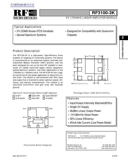
ü2P O W E R A M P L I F I E R SProduct DescriptionOrdering InformationTypical ApplicationsFeaturesFunctional Block DiagramRF Micro Devices,Inc.7628Thorndike RoadGreensboro,NC 27409,USA T el (336)6641233Fax (336)6640454Optimum Technology Matching® AppliedSi BJT GaAs MESFET GaAs HBTSi Bi-CMOSSiGe HBTSi CMOSVREG RF IN VCC1RF OUTGNDVCC2V M O D ERF3100-3K3V 1700MHZ LINEAR AMPLIFIER MODULE•3V CDMA Korean-PCS Handsets •Spread-Spectrum Systems•Designed for Compatibility with Qualcomm ChipsetsThe RF3100-3K is a high-power,high-efficiency linear amplifier IC targeting 3V hand-held systems.The device is manufactured on an advanced Gallium Arsenide Het-erojunction Bipolar Transistor (HBT)process,and has been designed for use as the final RF amplifier in dual-mode 3V CDMA hand-held digital cellular equipment,spread-spectrum systems,and other applications in the 1750MHz to 1780MHz band.The RF3100-3K has a digi-tal control line for low power application to reduce the cur-rent drain.The device is self-contained with 50Ωinput and output that is matched to obtain optimum power,effi-ciency,and linearity characteristics.The module is an ultra-small 6mmx6mm land grid array with backside ground.•Input/Output Internally Matched@50Ω•Single 3V Supply•28dBm Linear Output Power •-141dBm/Hz Noise Power•35%Linear Efficiency•45mA Idle Current (Low Power Mode)RF3100-3K 3V 1700MHz Linear Amplifier Module RF3100-3K PCBA Fully Assembled Evaluation Boardmm.Package Style: LGM (6mmx6mm)查询RF3100-3K供应商RF3100-3K2P O W E R A M P L I F I E R SAbsolute Maximum RatingsParameterRatingUnitSupply Voltage (RF off)+8.0V DC Supply Voltage (P OUT≤29dBm)+5.2V DC Control Voltage (V REG )+4.2V DC Mode Voltage (V MODE )+3.5V DC Input RF Power+10dBm Operating Case Temperature -30to +110°C Storage Temperature-30to +150°CParameterSpecification Unit ConditionMin.Typ.Max.High Power State (V MODE Low)Typical Performance at V CC =3.2V ,V REG =2.85V ,T AMB =25°C,Frequency=1750MHz to 1780MHz (unless otherwise specified)Frequency Range 17501780MHz Linear Gain25.527.5dB Second Harmonic -49dBc Third Harmonic-52dBc Maximum Linear Output Power(CDMA Modulation)28dBm Total Linear Efficiency 35%P OUT =28dBmAdjacent Channel PowerRejection -46-44.5dBc ************,P OUT =28dBm -60-57.5dBc************,P OUT =28dBm Input VSWR <2:1Output VSWR 10:1No damage.6:1No oscillations.>-70dBc Noise Power-141dBm/HzAt 90MHz offset.Low Power State (V MODE High)Typical Performance at V CC =3.2V ,V REG =2.85V ,T AMB =25°C,Frequency=1750MHz to 1780MHz (unless otherwise specified)Frequency Range 17501780MHz Linear Gain1720dB Second Harmonic -49dBc Third Harmonic-52dBc Maximum Linear Output Power(CDMA Modulation)16dBm Adjacent Channel PowerRejection -52-46.5dBc ************-66-61dBc************Input VSWR <2:1Output VSWR10:1No damage.6:1No oscillations.>-70dBcESD sensitive device.RF Micro Devices believes the furnished information is correct and accurate at the time of this printing.However,RF Micro Devices reserves the right to make changes to its products without notice.RF Micro Devices does not assume responsibility for the use of the described product(s).RF3100-3K2P O W E R A M P L I F I E R SParameterSpecification UnitConditionMin.Typ.Max.DC SupplyT AMB =25°CSupply Voltage 3.23.74.2V Quiescent Current170240mA V MODE =Low,V REG =2.85V5080mA V MODE =High,V REG =2.85VV REG Current 610mA V MODE Current 1.5mA Turn On/Off Time6µs Total Current (Power Down)510µA V REG =Low,V MODE =LowV REG “Low”Voltage 00.5V V REG “High”Voltage 2.8 2.852.9V V MODE “Low”Voltage 00.5V V MODE “High”Voltage2.03.0VRF3100-3K2P O W E R A M P L I F I E R SPin Function DescriptionInterface Schematic1VCC1First stage collector supply.A low frequency decoupling capacitor (e.g.,1µF)is required.2RF IN RF input internally matched to 50Ω.This input is internally AC-coupled.3VREG Regulated voltage supply for amplifier bias.In Power Down mode,both V REG and V MODE need to be LOW (<0.5V).4VMODE For nominal operation (High Power Mode),V MODE is set LOW.When set HIGH,devices are turned off to improve efficiency.5VCC2Output stage collector supply.A low frequency decoupling capacitor (e.g.,1µF)is required.6RF OUT RF output internally matched to 50Ω.This output is internally AC-coupled.7GND Ground connection.Connect to package base ground.For best perfor-mance,keep traces physically short and connect immediately to ground plane.Pkg BaseGNDGround connection.The backside of the package should be soldered to a top side ground pad which is connected to the ground plane with mul-tiple vias.The pad should have a short thermal path to the ground plane.RF3100-3K2P O W E R A M P L I F I E R SEvaluation Board Schematic(Download Bill of Materials from .)J6RF OUTJ2RF INVCC1VMODE VCC2VREGRF3100-3K2P O W E R A M P L I F I E R SEvaluation Board Layout Board Size 1.5” x 1.5”Board Thickness 0.032”,Board Material FR-4,Multi-Layer,Ground Plane at0.014”。
3100溶氧仪中文操作手册
2.1 技术规格..................................................................................................................................... 11 2.2 仪器尺寸..................................................................................................................................... 12 2.3 一般运行原理 ............................................................................................................................. 13
文档编号 DG3100-MAN/CN
ORBISPHERE Model 3100 便携式 O2 分析仪
用户手册 2010 年 9 月,修订 A
目录
第 1 章 一般信息 .................................................................................................................................. 3
3100型定义目的开关器产品说明书
3100-15T1999Products Unlimited 3100, Definite Purpose Contactors, Pole Configuration 1, 120VACCoil Voltage Rating, 25A Contact Current Rating, Panel08/26/2020 11:09PM | Page 1 For support call+1 800 522 6752Relays, Contactors & Switches>Contactors>Definite Purpose Contactors>DP CONTACTORS, 1 POLEContact Arrangement: 1 Form X, SPST-NO-DM with ShuntMounting Type:PanelContact Current Rating:25 ACoil Voltage Rating:120 VACPole Configuration:1All DP CONTACTORS, 1 POLE (12)FeaturesProduct Type FeaturesMolded NoProduct Category Electromechanical RelaysProduct Type ContactorArc Cover WithoutProduct Classification Relays - ContactorsModel96Contactor Type Definite PurposeTerminal Configuration10-32 Screw, Quick ConnectElectrical CharacteristicsActuating System ACCoil Voltage (Max)120 VACCoil Voltage Rating120 VACCoil Resistance444 ΩContact Switching Voltage (Max)600 VACContact FeaturesContact Base Material Silver Cadmium OxidePole Configuration1Contact Current Rating25 A3100-15T1999 ACTIVEProducts UnlimitedTE Internal #:8-1611007-5Products Unlimited 3100, Definite Purpose Contactors, PoleConfiguration 1, 120VAC Coil Voltage Rating, 25A Contact CurrentRating, PanelView on >Products Unlimited 3100|Pole Configuration1Contact Current Rating25 AContact Arrangement 1 Form X, SPST-NO-DM with ShuntTermination FeaturesCoil Termination Quick ConnectMechanical AttachmentMounting Plate WithMounting Type PanelDimensionsWire Size 1.31 – 8.37 mm²Industry StandardsUL Flammability Rating UL 94V-0Agency Approval CSA Certified, SEMKO Certified, ULRecognizedPackaging FeaturesPackaging Method Loose PieceOtherComment Stranding must be split for 8 AWG wire.Torque25 in-lbsProduct ComplianceFor compliance documentation, visit the product page on >EU RoHS Directive 2011/65/EU Compliant with ExemptionsEU ELV Directive 2000/53/EC Not CompliantChina RoHS 2 Directive MIIT Order No 32, 2016Restricted Materials Above ThresholdEU REACH Regulation (EC) No. 1907/2006Current ECHA Candidate List: JUN 2020(209)Candidate List Declared Against: JAN 2019(197)Does not contain REACH SVHCHalogen Content Not Yet Reviewed for halogen contentSolder Process Capability Not applicable for solder process capabilityProduct Compliance DisclaimerThis information is provided based on reasonable inquiry of our suppliers and represents our current actual knowledgebased on the information they provided. This information is subject to change. The part numbers that TE has identified asEU RoHS compliant have a maximum concentration of 0.1% by weight in homogenous materials for lead, hexavalent08/26/2020 11:09PM | Page 2 For support call+1 800 522 675208/26/2020 11:09PM | Page 3For support call+1 800 522 6752EU RoHS compliant have a maximum concentration of 0.1% by weight in homogenous materials for lead, hexavalent chromium, mercury, PBB, PBDE, DBP, BBP, DEHP, DIBP, and 0.01% for cadmium, or qualify for an exemption to these limits as defined in the Annexes of Directive 2011/65/EU (RoHS2). Finished electrical and electronic equipment products will be CE marked as required by Directive 2011/65/EU. Components may not be CE marked.Additionally, the part numbers that TE has identified as EU ELV compliant have a maximum concentration of 0.1% by weight in homogenous materials for lead, hexavalent chromium, and mercury, and 0.01% for cadmium, or qualify for an exemption to these limits as defined in the Annexes of Directive 2000/53/EC (ELV). Regarding the REACH Regulations, TE’s information on SVHC in articles for this part number is still based on the European Chemical Agency (ECHA) ‘Guidance on requirements for substances in articles’(Version: 2, April 2011), applying the 0.1% weight on weight concentration threshold at the finished product level. TE is aware of the European Court of Justice ruling of September 10th, 2015 also known as O5A (Once An Article Always An Article) stating that, in case of ‘complex object’, the threshold for a SVHC must be applied to both the product as a whole and simultaneously to each of the articles forming part of its composition. TE has evaluated this ruling based on the new ECHA “Guidance on requirements for substances in articles” (June 2017, version 4.0) and will be updating its statements accordingly.TE Model / Part #5-1437595-9TRD11H10WL=ROCKER GOLD ON OFFTE Model / Part #2-1393117-4KUP-11A25-120=KUTE Model / Part #62718-1FASTON .250 FLAG REC 22-18 AWG BRTE Model / Part #6-1393118-0KUP-5A15-24=KUDefinite Purpose Contactors(80)TE Model / Part #175022-1PL EX MKII 250 REC 18-14AWG PTBRTE Model / Part #CAT-P592-SP118PIDG SPADE TONGUE TERMINALSTE Model / Part #CAT-P592-R472A PIDG RING TONGUE TERMINALSCompatible PartsAlso in the Series Products Unlimited 3100Customers Also BoughtDocumentsCAD Files3D PDF3D3D PDF3DCustomer View ModelENG_CVM_CVM_8-1611007-5_D.2d_dxf.zipEnglishCustomer View ModelENG_CVM_CVM_8-1611007-5_D.3d_igs.zipEnglishCustomer View ModelENG_CVM_CVM_8-1611007-5_D.3d_stp.zipEnglishBy downloading the CAD file I accept and agree to the of use.Terms and ConditionsDatasheets & Catalog PagesModel 96 - 3100 Definite Purpose Contactor 1- or 2-pole, 20-40 FLA AC CoilEnglishIndustrial Relays Quick Reference GuideEnglish08/26/2020 11:09PM | Page 4 For support call+1 800 522 6752。
OTIS3100R2调试手册200401
第一章SM-01-F简介……………………………………………………………1
第二章SM-02-B简介……………………………………………………………8
第三章SM-03-B简介………………………………………………………….….11
第四章SM-04-VHL显示板………………………………………………….….15
JP1.9:输入X8,下行单层终端换速开关.(输入类型可更改,出厂值是常闭触点)
JP1.10:输入X9,上平层干簧(输入类型可更改,出厂值是常开触点)
JP2.1:输入X10,下平层干簧(输入类型可更改,出厂值是常开触点)
JP2.2:输入X11,调速器故障输出信号(输入类型可更改,出厂值是常开触点)
JP2.3:输入X12,消防开关(输入类型可更改,出厂值是常开触点)
JP2.9:输入X18,门区信号输入,用于开门再平层和提前开门,闭合有效
(输入类型可更改,出厂值是常开触点)
JP2.10:输入X19,调速器运行信号检测,检测到此信号闭合则抱闸可以张开(输入类型不可更改)
JP3.1:输入X20,提前开门继电器检测(输入类型不可更改)
JP3.2:输入X21,备用
JP3.3:输入X22,抱闸开关检测-
JP4.2: TXA1+
JP4.3: TXV- (0V电源输出)不接
JP4.4: TXV+ (+24V电源输出)不接
为避免电源干扰,要求24V通讯电源从开关电源直接供电。
★JP5.1-JP5.4(CAN2)作并联或群控用,作并联时只要连接对应两台主机的
JP5.2,JP5.3,JP5.4三根线
第十章常见故障诊断……………...………………………………………...61
3100电脑用户手册

user manual DELCOS 31001.1 41.1.1 4 1.1.2 5 1.1.3 6 1.1.4 —— 1 6 1.1.5 —— 2 6 1.2 DELCOS 3100 81.2.1 [ ] 9 1.2.2 [ ] 9 1.2.3 [ ] 9 1.2.4 [ ] 10 1.2.5 [ ] 10 1.2.6 [ ] 10 1.2.7 12 1.2.8 12 1.2.9 13 1.3 131.3.1 13 1.3.2 14 1.3.3 14 1.3.4 14 1.3.5 14 1.3.6 14 1.3.7 14 1.3.8 / 14 1.3.9 15 1.4 DELCOS 3100 161.4.1 16 1.4.2 / 16 1.5 201.6 201.6.1 20 1.6.2 20 1.6.3 21 1.6.4 21 1.6.5 22 1.6.6 23 1.6.7 RS485 23 1.7 231 1.11.1.1I => O =>=>=>=> 1 / /=> 2=>MENUC =>=>=>=>=>=>21.1.2LED a => LED e =>LED b =>LED c => ONLED f =>LED d => LED g =>LED h =>LED f LED g LED h1.3.4 1.3.91.1.3 1.1.5 —— 2DELCOS 3 100 17 ⎭ 2ΘLED READY TO STARTb=>OFF ,Bar,PSI. WARNING START WITH1.1.4 —— 1 PRESSURE REQUIREMENT11 => R2 WARNING START AFTER2 => B23 => B1 DE-PRESSURISE2 FAULTSENSOR WARNING START WITHTIMER CONTROLWARNING START BYREMOTE OPERATIONREMOTE ONxxS WARNING START IN xxS MAINTENANCE ELAPSED AFTER POWER LOSS 12 3xx 1.5 MOTOR START PHASEOFF-LOADON-LOADxxS SOFT STOP xxsxxyyS RUN ON TIMER yys< > FAULT < >< > WARNING < >31.41.2.4 [ ] FREE[ ] LIMITVALUES ● input1 DISCH TEMP[ ● input2 EXT FAULT ] ● input3 FREE● DESIGN PRESS 13.0bar/188p● START PROTECT si● FINAL TEMP 0 .8bar/11psiWARN 110 /230F● FINAL TEMP 1.2.6 [ ]MAX 120 /248F (TIMER CONTROL)● MIN START TEMP● RUN-ON TIME 1● SOFT STOP 360● / STAR/DELTA TIME 30● SOFTWARE: 8SD31V1.00 [] TIMER CONTROL OFF1.2 8.) [ ] [ ](SWITCH ON)[ ](TIMER CONTROL)1.2.5 [ ][ ][ ] [ 29.01.94 13:55:14] OPTIONAL INPUTS ● [⎭] [SA]●[ ] / ● [⎭]● [29]●● [⎭]OIL PRESS [⎭]OIL LEVELEXT FAULT [Θ]DISCH TEMPOIL TEMP/ ROT/BELTS— B1 OPERATE-B1 1.6.327 6:00 22:002[2_________00:00 00:00] [1_M_______ 06:00 24:00]1 [2__TWT___ 00:00 24:00]07:30 16:15 [3_____F____ 00:00 22:00] [1__MTWTF__07:30 16:15] [4__________ 00:00 00:00][5__________ 00:00 00:00] [1_________00:00 00:00] [6__________ 00:00 00:00]● [⎭] Sunday [7__________ 00:00 00:00]●● [⎭]● Monday●● [⎭] [ (REDUCE) 22:00 06:00][ (EDUCE BY) 1.5 bar]22:00 6:00 [Θ] 1.5[ ]1 [ 9.0 bar]22:00 14:00 [ 10.0 bar]12:00 12:30 7.5 8.5 bar[ ] [1S________ 22:00 24:00][2_MTWTFS 00:00 12:00] [ ]] [ ][3_MTWTF_ 12:30 24:00][4_______S 12:30 14:00][5________ 00:00 00:00][6________ 00:00 00:00][7________ 00:00 00:00] [ 00:00 00:00] /[ 0.0 bar]1.2.7● [C]1.2..8 ● [⎭][ ][⎭] CODE LOCK 1CODE INPUT 0000[3031][⎭]CODE UNLOCK1[Θ]CODE LOCK11.2.8[C]CODE UNLOCK1CODE INPUT 0000[3031]CODE LOCK1CODE UNLOCK11.3LED a1.3.1LED [Θ][I]1.2.4 []DELCOS 3 100 LED a[WARNING START WITH]1.1.5SETUP-CODE 1:_______[⎭]CODE 2 21 [⎭] 23 1 2 [I]1 ON●●●DELCOS 3100 * [ ]1.2.5 *1.3.2 1.3.5LED gLED a1.3.6LED f/ [ ][ ] 1.2.11.5[ ]1.3.71.3.3O 30 [ ]250V/1A1.3.41.3.8 /LED h [ ][ ](TOTA RUNNING) [](LOADED HOURS) 1.2.1[Θ][ ] LED[Θ]DELCOS 3100[ ]1.3.9/1.2.3 [ ]/ /12! MOTOR TEMP 12345h.* 12 12*MOTOR TEMP*12345h 1234588// //1.4 DELCOS 3100 8.9.1.4.110.11.- /1. -2. --3. 55 -4./ / -20 -5.1.4.2 /6. DELCOS 31007.1 10 1.2.4[ ]2 9 1.2.1[ ]3 10 1.2.5[ ]4 9 1.2.2[ ]5 10 1.2.6[ ]。
NTRON3100氧气分析仪 中文操作手册
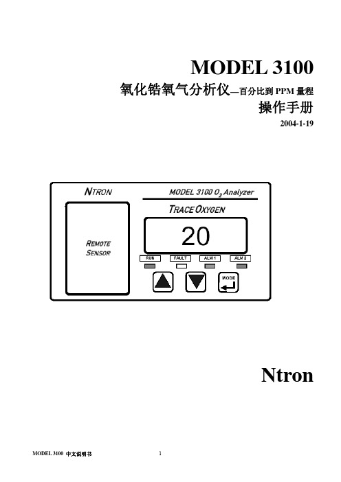
MODEL 3100 氧化锆氧气分析仪—百分比到PPM量程操作手册2004-1-19Ntron目录安全提示 (3)第一部分操作原理1.1概括 (4)1.2特征 (4)1.3系统组成 (5)1.4 分析仪输入与输出 (7)1.5 控制面板 (8)第二部分 1100分析仪操作2.1安装 (10)2.1.1 分析仪的安装位置 (10)2.1.2 远传传感器的安装 (11)2.1.3 分析仪安装 (11)2.2开始 (15)2.2.1 通电 (15)2.2.2 校准 (15)2.2.3 报警设置 (15)第三部分操作形式3.1系统机构 (16)3.2 用户形式 (16)3.3 系统模式 (17)第四部分维护 (19)4.1系统设置 (19)4.2定期维护表格 (28)4.3 发现并维修故障 (28)安全提示:安装或操作之前请详细阅读操作手册。
在没有完全明白型号3100的特征和功能之前而进行操作,可能会造成危险。
⏹气体加压时,使用保护眼罩和遵守安全的程序。
⏹测量气体要在相同压力和流速下校准。
⏹确保在使用之前已经校准仪器。
⏹3100分析仪外壳不具有防水功能,避免放置在液面,潮湿等地方。
⏹不要放置在易燃或高温环境的地方。
⏹3100分析仪不具有防爆等级或本安型,避免放置在有易燃气体或水蒸汽的地方。
⏹确保分析仪的操作温度,不要置于高温的表面,不要阻塞通风口。
第一部分操作原理1.1概括Ntron 公司的3100系列分析仪,它提供了在微氧测量和控制运用中的有效解决。
它针对于精确测量百分比范围氧而设计的分析仪。
氧气精确测量从0.1PPM到100%。
3100分析仪内置Ntron公司的远控传感器机箱(RSM),传感器机箱的主体部分是Ntron公司独有的“氧化锆传感器”。
氧化锆传感器是一个具有可靠性和反映快功能的固态装置,由于它是固态,所以不受干燥环境影响,在极冷的冷藏库下不受损坏。
3100分析仪的全图:1.2 特征型号3100分析仪为嵌板或控制台的装置。
SUNTEX PC-3100 3100RS 传送器 操作说明书
2.4. 2
PP-100A 組裝方式:
A------圓形接線盒上蓋 B------O 形環 C------電纜固定頭 MG16A D------圓形接線盒下蓋 E------電纜固定頭 MG16A F------ O 形環 G------PP 電極保護管 H------感測電極 I-------橡膠電極座 J------PP 管保護套
1 5 6 6 7 7 7 8 9 11 11 12 12 13 14 14 15 15 16 16 17 17 17 17 17 17 17 18 19 19 20 21
6.5 自動恢復式測量模式------------------------------------------- 22
3
6.6 高點 Hi 值警報設定模式 6.7 低點 Lo 值警報設定模式 6.8 自動清洗時間設定 6.9 輸出電流對應 pH/ORP 量测範圍設定 6.10 輸出電流對應溫度量測範圍設定(僅適用於 PC-3100)
1. 2. 3. 4. 5. 6. 7. 8.
(H)感測電極纜線穿過(G)PP 電極保護管。 先將(H)感測電極適當潤濕,以方便穿入(I)橡膠電極座內,下沿露出約 5cm。 將套好之(I)橡膠電極座套回(G)PP 電極保護管內,並將(J)PP 管保護套鎖緊。 將(H)感測電極之纜線穿過(D)圓形接線盒下蓋及(C)電纜固定頭,將(D)圓形接線盒下 蓋緊套住(G)PP 電極保護管。 預留 15cm 纜線於 PP 管內後將(C)電纜固定頭 MG16A 鎖緊,並於上方預留(H)感測電極之 纜線約 12-14cm 後,依電極纜線開線法開線。 將電極中心軸端子固定在圓形接線底座 1 號端子座上,將電極網線端子固定在 3 號端子座 上。 (見接線盒接線說明圖) 延長纜線穿過(D)圓形接線盒下蓋上的(E)電纜固定頭,並將(E)電纜固定頭 MG16A 鎖 緊,留 12-14cm 在盒內開線。 延長導線中心軸與電極中心軸並接,延長纜線網線固定在 3 號端子座上並接,鎖緊(A)圓 形接線盒上蓋,完成組裝。
Personal Storage 3100 安装指南说明书

Personal Storage 3100 Inable Connections
1. Plug the larger end of the USB cable into available USB port on your computer.
Personal Storage 3100 Installation Guide
Windows PC Software Setup:
Windows Millennium/2000/XP
Maxtor has completely prepared your new personal storage 3100 with one large FAT32 partition. After you connect the drive to your computer (see Part 3 Hardware - Installation for more information), Windows will detect the "USB Mass Storage Device" and install the drivers for it. Allow up to two minutes for your computer to recognize the drive. Restart your system. Your drive is now ready to use.
computer to which you connect the Personal Storage to. Maxtor suggests that you extract the file to the C:\> drive. 2. Browse to the C:\PS3100_98SE_Drivers folder and double-click on the 3100_98SE_Drivers file. This will launch the InstallShield Wizard.
AMRI-3100光学传感器瘦胖滚轮5方向开关设计指南说明书

Applications
• Handheld electronic devices • Mobile devices • Digital cameras and camcorders • Entertainment consoles • Handheld GPS or navigation devices • Portable audio and video players • Photo printers
Output (with optional component) • Single 2.4V to 3.3V supply • Simple Power Down feature (with optional component) • Easy assembly, no signal adjustment required • Customizable aesthetic design • -15°C to 70°C operating temperature • Ease of assembly
The light from the emitter that beams onto the rotating code wheel placed underneath the dial of scrollwheel is reflected onto the photo-detector IC. As the code wheel
Figure 1. Illustration on the scrollwheel operation
Emitter VCC GND
Window (Reflective)
Processing Circuitry
Bar
ChA
(Non-Reflective)
3100 宏量移液器 操作说明书
ORDERING INFORMATIONPIPETTE DISPOSABLE TIPCat.No. Volume Range Cat.No. Capacity Q’ty/Bag 00‐31N‐1000 0.2~1.0mL 00‐MPT‐1 0.2~1.0mL 100000‐31N‐2000 0.4~2.0mL 00‐MPT‐2 0.4~2.0mL 20000‐31N‐5000 1.0~5.0mL 00‐BMT2‐X 1.0~5.0mL 20000‐31N‐10000 2.0~10.0mL 00‐BMT2‐Z 2.0~10.0mL 200Model 3100 is provided with accessories as follows.*One Piston Installing Tool*One grease*Tip(s) : 00‐31N‐1000 with 2pcs(00‐MPT‐1) , 00‐31N‐2000 with 2pcs(00‐MPT‐2), 00‐31N‐5000 with 1pc(00‐BMT2‐X), 00‐31N‐10000 with 1pc(00‐BMT2‐Z).*An operation manualFor repair service or further information you may contact your local distributor:MANUFACTURER:2014.Ver.1CERTIFIED ISO9001● Thank you very much for purchasing MODEL 3100 ● Please read this manual carefully before using.Always Pursuing Originality Since 194421L4lm35OOCKLMODEL 3100MACROPIPETTEFEATURES•Excellent accuracy and precision.•Four different volume ranges, 1mL, 2mL, 5mL and 10mL.•Volume of pipetting is easily changed and fixed.•Light design permits easy handling without fatigue.SPECIFICATIONSAccuracy: ± 1.0% Reproducibility Precision: ≤ 1.0%Cat.No. Volume Range Increments00‐31N‐1000 0.2~1.0mL 0.1mL00‐31N‐2000 0.4~2.0mL 0.1mL00‐31N‐5000 1.0~5.0mL 0.5mL00‐31N‐10000 2.0~10.0mL 0.5mLOPERATING PROCEDURES1. Loosen the lock nut and turn the push button until the yellow cross‐line corresponds to the desired volume indicated by the volume scale, then lock by tightening the lock nut.2. Attach a disposable tip firmly onto the syringe nozzle.3. Depress thepush button several times to ensure smooth movement of the piston. Push the push button to the first stop. (Fig. 1, B)4. Place the disposable tip into liquid to a depth of 3 to 4mm.5. Slowly return the push button to its original “up” position. (Fig. 1, A) The sample will be drawn into the tip. The push button should be carefully released so not to flush the liquid into the tip of the pipette, especially for 5mL and 10mL model.6. Touch the tip to the inside wall of the receiving vessel.7. Press the push button again to the first stop to dispense most of the liquid.Wait one second with the push button Held in this position, then continue to push the push button to its limit(Fig. 1, C).This forces out the last remaining liquid from the tip. Keep the knob fully depressed until the tip is removed from the receiving vessel. Remove used tip from the pipette.ABCFig.1REPLACEMENT OF PARTS1. PUSH BUTTON – It is easily removed by pulling it off the push button.2. SYRINGE – Turn it counterclockwise to remove from the syringe connector. (Fig. 3)3. PISTON – After removal of the syringe, keep the push button fully depressed, and push a pin by the probe of the piston installing tool. To install thepiston, push the pin by opposite side of the tool. (Fig. 4)Note:The piston should be lubricated with a small amount of silicone grease provided after certain interval or after cleaning of the piston when contaminated.Syringe Connector Plunger PinPiston InstallingTool(to remove)(to install)Piston Fig.4PARTS AND MATERIALS①Push Button (Polypropylene)②Shaft(Stainless Steel)③Lock Nut (Alumite platedAluminium)④Volume Scale (Polymethylpentene)⑤Body (Polypropylene)⑥Syringe Connector (Polypropylene)⑦Piston(Fluoroplastic)⑧Syringe (Polypropylene)⑨Disposable Tip (Polypropylene)①②③④⑤⑥⑦⑧⑨⑩41235mlFig.2Syringe NozzleSyringeSyringe ConnectorFig.3。
