ABB:Vmax技术说明
ABB机器人常用指令详解-中文(二)

RAPID 参考手册-RAPID 概述,运动和 I/O 原理-坐 标系部分 RAPID 参考手册—RAPID 概述,运动和 I/O 原理—用 逻辑指令同步部分
1.92.MoveExtJ-移动一个或者多个没有 TCP 的机械单元
用途: MoveExtJ(移动外部关节)只用来移动线性或者旋转外部轴。该外部轴可以属于一个或者多个没有 TCP 的
MoveeExtJ j1, rot_ax_speed, fine;
MoveeExtJ j2, rot_ax_speed, z20;
MoveeExtJ j3, rot_ax_speed, z20;
MoveeExtJ j4, rot_ax_speed, fine
在该例子中,旋转独立轴移动到轴位置 0, 30, 60 和 90 度,移动速度为 45 度/秒。
工具 tool2 的 TCP 沿着一个非线性路径到位置 p1,速度数据是 vmax,zone 数据是 z30。 例 2 MoveJ *, vmax \T:=5, fine, grip3;
工具 grip3 的 TCP 沿着一个非线性路径运动到存储在指令中的停止点(用*标记)。整个运动需要 5 秒钟。 项目:
MoveJ [\Conc] ToPoint [\ID] Speed [\V] | [\T] Zone [\Z] [\Inpos] Tool [\WObj] [ \Conc ]:
并发事件 数据类型:switch 当机器人运动的同时,后续的指令开始执行。该项目通常不使用,但是当使用飞点(flyby points)时,可 以用来避免由 CPU 过载引起的不想要的停止。当使用高速度并且编程点相距较近时这是很有用的。例如,当不 要求与外部设备通讯或外部设备和机器人通讯同步的时候,这个项目也很有用。 使用项目\Conc 的时候,连续的运动指令的数量限制为 5 个。在包括 StorePath—RestorePath 的程序段中不 允许使用带有\Conc 项目的运动指令。 如果不使用该项目,并且 ToPoint 不是停止点,在机器人到达程序 zone 之前一段时间后续指令就开始执行 了。 在多运动系统中的坐标同步运动中不能使用该项目。 ToPoint: 数据类型:robtarget 机器人和外部轴的目标位置。定义为一个命名的位置或者直接存储在指令中(在指令中用*标记)。 [ \ID ]: 同步 ID 数据类型:identno 该项目必须使用在多运动系统中,如果并列了同步运动,则不允许在其他任何情况下使用。 指定的 ID 号在所有协同的程序任务中必须相同。该 ID 号保证在 routine 中运动不会混乱。 如果并列了同步运动,不允许在其他任何情况下使用。
VMAX 10K产品技术手册

目录
• 系统架构 • 引擎架构 • I/O模块 • 引擎配置 • 存储柜 • 系统电源 • 系统组件 • 存储监控 • 存储维护
20
Power Distribution Panel (PDP)
• 单相电 • 提供到客户电源的接口 • 每个机柜2个 • 提供on/off 开关 • 可以从机柜的后门访问On/Off开关
4
系统柜 3 & 4
6 DAE’s
Engine 3
SPS to Provide Battery Backup for Engine
4 DAE’s
SPS to provide Battery Backup for Vault DAEs
5
摆放顺序
System Bay 1 Engine 1
Director 1&2
电池故障例子:
• System Bay
•
Bay Name
: SystemBay
•
Number of Fans
:0
•
Number of Power Supplies
:2
•
Number of Standby Power Supplies : 2
•
Status of Contained Modules
•
Fans
Fri Mar 16 11:42:22 2012 FA-2C Symm Device(004B) Warning 0x0016
A device has a mirror that is Not Ready
Fri Mar 16 11:44:34 2012 FA-1D Symm Device(00A6) Warning A device has a mirror that is Not Ready
ABB机器人实用手册

一、系统安全以下的安全守则必须遵守,因为机器人系统复杂而且危险性大,•万一发生火灾,请使用二氧化炭灭火器。
•急停开关(E-Stop)不允许被短接。
•机器人处于自动模式时,不允许进入其运动所及的区域。
•在任何情况下,不要使用原始盘,用复制盘。
•搬运时,机器停止,机器人不应置物,应空机。
•意外或不正常情况下,均可使用E-Stop键,停止运行。
•在编程,测试及维修时必须注意既使在低速时,机器人仍然是非常有力的,其动量很大,必须将机器人置于手动模式。
•气路系统中的压力可达0.6MP,任何相关检修都要断气源。
•在不用移动机器人及运行程序时,须及时释放使能器(Enable Device)。
•调试人员进入机器人工作区时,须随身携带示教器,以防他人无意误操作。
•在得到停电通知时,要预先关断机器人的主电源及气源。
•突然停电后,要赶在来电之前预先关闭机器人的主电源开关,并及时取下夹具上的工件。
•维修人员必须保管好机器人钥匙,严禁非授权人员在手动模式下进入机器人软件系统,随意翻阅或修改程序及参数。
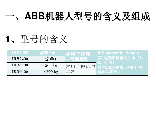
第一章综述一、S4C系统介绍:全开放式对操作者友善最先进系统最多可接六个外围设备常规型号:IRB 1400,IRB 2400,IRB 4400,IRB 6400IRB 指 ABB 机器人,第一位数(1,2,4,6)指机器人大小第二位数( 4 )指机器人属于S4或S4C系统。
无论何型号,机器人控制部分基本相同。
IRB 1400:承载较小,最大承载为5kg,常用于焊接。
IRB 2400:承载较小,最大承载为 7kg ,常用于焊接。
IRB 4400:承载较大,最大承载为60kg 常用于搬运或大范围焊接。
IRB 6400:承载较大,最大承载为200kg,常用于搬运或大范围焊接。
二、机器人组成:机器人由两部分组成:Controller: 控制器。
Manipulator: 机械手。
操作人员通过示教器和操作盘操作机器人。
左边是示教器(Teach Pendant)。
ABB:UniGear 550概述
编号:1YHA000080
- REF542+ 保护继电器
编号:1YZA000003
质量体系 符合ISO 9001:2000标准,经由第三方独立机构认证。
环境管理体系 符合ISO 14001:2004标准,经由第三方独立机构认证。
职业健康与安全管理体系 符合OHSAS 18001:1999标准,经由第三方独立机构认证。
电磁场由电弧本身产生,切线方向的 电流分量产生的磁场导致电弧围绕触 头轴线快速旋转。
相比固定不动的收缩型电弧,被驱动 旋转的电弧掠过了更大范围的触头表 面。
这种方式,不光减少了触头上的热应 力、大幅减小了触头的烧蚀,还使极 高短路电流的真空开断变得可能。
ABB的真空灭弧室属于电流零点开断 灭弧室,无重击穿。
665 461 660 150
121
1YHT350003 -15...+40
33...60 10...15 45...75 45...80
665 461 660 150
121
1YHT350003 -15...+40
13
断路器选择和订货
固定式断路器基本配置 基本的固定式断路器配置如下: - EL型操动机构 - 合闸弹簧储能/未储能机械信号装置 - 断路器分合闸机械信号装置 - 合闸按钮 - 分闸按钮 - 合闸计数器 - 十点断路器分合闸信号辅助触点(1)
5
概述
ABB 真空灭弧室的开断原理
1 2 3 4 5
6 7 8 9
10பைடு நூலகம்
1 出线杆 2 扭转保护环 3 波纹管 4 端盖 5 屏蔽罩 6 陶瓷绝缘外壳 7 屏蔽罩 8 触头 9 出线杆 10 端盖
在一个真空灭弧室内,真空电弧随着 载流触头的分离而产生,并维持到电 流过零点结束,电弧可受到磁场的影 响。
ABB机器人标准指令详解

ABB机器人标准指令详解一、 RAPID程序控制指令1、1程序开始/结束控制指令1) PROGRAM START/END1、指令格式: PROGRAM <程序名> <属性> ;2、描述:此指令标识一个机器人程序的开始或结束。
在这里,<程序名>是你给程序取的名字,<属性>是可选的,表示程序的属性(如:INTERLOCK, NO_INTERLOCK, NOPROGRAM等)。
2) JOB START/END1、指令格式: JOB <作业名> <属性> ;2、描述:此指令标识一个作业的开始或结束。
在这里,<作业名>是你给作业取的名字,<属性>是可选的,表示作业的属性(如:INTERLOCK, NO_INTERLOCK, NOPROGRAM等)。
1、2程序转移指令1) GOTO1、指令格式: GOTO <行号>;2、描述:此指令将程序执行转移到指定的行号。
2) GOSUB1、指令格式: GOSUB <行号>;2、描述:此指令将程序执行转移到指定的行号,并在返回时继续执行当前行。
3) RETURN1、指令格式: RETURN;2、描述:此指令将程序执行从 GOSUB转移到父程序,并从 GOTO转移到原程序行。
1、3条件判断指令1) IF/THEN/ELSE/ENDIF;1、指令格式: IF <条件> THEN <表达式> ELSE <表达式> ENDIF;2、描述:如果满足条件<条件>,则执行 THEN后面的表达式;否则执行 ELSE后面的表达式。
2) CASE/ESAC/ENDCASE;1、指令格式: CASE <变量> IN <表达式1> / <表达式2> /... / ENDCASE;2、描述:此指令根据变量<变量>的值选择要执行的表达式。
ABB Vmax_12[1]...17.5kV真空断路器技术参数表
![ABB Vmax_12[1]...17.5kV真空断路器技术参数表](https://img.taocdn.com/s3/m/69aa191da300a6c30c229fc6.png)
f ¢e
x c ` dab&Y
X¢W
kg mm mm
¤ ¤¾ ¿ ¿ ¸ t £$£"$¤¾ &· Ö £1 uk &· ¸ ¤ "1 k &· ¸ ¡ £¤~ Í Ó&rm s &¢b y $Y n ¡ ¢£¤~ Í &kb Ó ¡ ¶ ¢£¤~ $£&| Í ä t ¦& â · k$x ¤$ ©St ¦& h ¤ õ '&· ¸ £"£v q y x w p h t q ¢ ï e uÍ $rsSp$ rib&g v $½ã gA q p e h ¾ q ¿ ¢ c ø ä bp ¤£½ô ø¢d c ø¢¤¾ ¿ bp ¤¾ qc ¿ Q V
(C-O) BIL
8.6 8.7
8.8
8.7.1 8.7.2 8.7.3
A A kA A kV kV
A
A
A A
0.8Ir 400 20 at 4250Hz <5 75/95 42/38 , 25/31.5 1250 75 2.5 p.u. ABB
Ö q&í
9 10 11 12
: (rms), TRV (Uc), t3, td, U', t', RRRV
6
1 2 3 42 4.3
6.1 6.2
5.1
5.1.1 5.1.2 5.1.3 5.1.4
5.2.1 5.2.2
kA Isc Idc% 40% kA 2.5 * Isc 1.5
ms
ABB高压柜现场操作运行规程

ABB高压柜现场操作运行规程1、范围◆本规程规定了ABB高压柜现场电气操作的安全注意事项。
◆本规程规定了ABB高压柜的各项规范操作步骤,如断路器基本的操作、手车基本的操作、就地与远方的合/分操作、接地开关的合/分操作、柜门关闭和开启的操作、柜间和柜外的联锁操作,微机保护装置REX521和REF610的基本操作。
◆本规程规定了ABB高压柜送电/停电的规范操作步骤。
◆本规程仅适用于中国厦门ABB生产的UniGear550型高压柜2、概述KPC管道项目ABB高压柜数量共24台,分4个站(2#、4#、6#、8#),每个站共有6台,分别为:进线柜 1台,PT柜 1台,站用变压器1台,电机柜 3台( 1台备用),一路电源供电。
ABB高压柜型号:UniGear550 真空断路器型号:Vmax/L 微机型号:REF610——进线柜、站用变压器柜REX521——电机柜电压等级:一次母线电压,二次测量电压AC110V ,二次控制电源DC110V,加热照明AC24OV电流等级:进线柜600/5A 变压器柜50/5A 电机柜300/5A 零序CT变比均为250/5A带接地开关情况:除PT柜没有带接地开关外,进线柜、站用变压器、电机柜都带有接地开关。
3、ABB高压柜现场电气操作安全注意事项。
、遵守KPC泵站配电室电气操作各项安全守则。
、配戴相关安全保护用具,如安全帽、绝缘手套、绝缘鞋等。
、高压设备操作人员必须有高压操作证,已签发工作票,办理工作许可证,有现场监护人。
、熟悉作业现场,明确工作区域,明确现场作业内容、操作步骤和方法。
、高压送电/停电操作前,应做好相关的安全防护工作,如设置防止误入带电设备区域的防护栏,拉警戒线,挂好安全警告标识牌,组织人员看护等。
、高压送电操作前,建议在高压柜前面的地板上,铺设绝缘橡胶垫。
、在相关检查及防护工作完成后,可以对高压柜进行送电/停电前检查及操作。
4、ABB高压柜的各项规范操作步骤▲ABB高压柜除了具有最基本的开关柜“五防”联锁功能外,还设置了其它的安全闭锁装置,对ABB高压柜的各项操作之前,也请参阅相关使用说明书。
ABB变频器参数
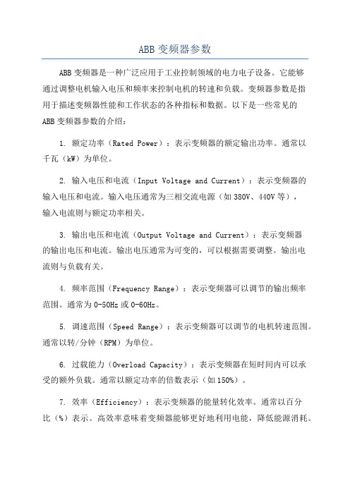
ABB变频器参数ABB变频器是一种广泛应用于工业控制领域的电力电子设备。
它能够通过调整电机输入电压和频率来控制电机的转速和负载。
变频器参数是指用于描述变频器性能和工作状态的各种指标和数据。
以下是一些常见的ABB变频器参数的介绍:1. 额定功率(Rated Power):表示变频器的额定输出功率。
通常以千瓦(kW)为单位。
2. 输入电压和电流(Input Voltage and Current):表示变频器的输入电压和电流。
输入电压通常为三相交流电源(如380V、440V等),输入电流则与额定功率相关。
3. 输出电压和电流(Output Voltage and Current):表示变频器的输出电压和电流。
输出电压通常为可变的,可以根据需要调整。
输出电流则与负载有关。
4. 频率范围(Frequency Range):表示变频器可以调节的输出频率范围。
通常为0-50Hz或0-60Hz。
5. 调速范围(Speed Range):表示变频器可以调节的电机转速范围。
通常以转/分钟(RPM)为单位。
6. 过载能力(Overload Capacity):表示变频器在短时间内可以承受的额外负载。
通常以额定功率的倍数表示(如150%)。
7. 效率(Efficiency):表示变频器的能量转化效率。
通常以百分比(%)表示。
高效率意味着变频器能够更好地利用电能,降低能源消耗。
8. 控制方式(Control Modes):表示变频器采用的控制方式,常见的有开环控制、闭环控制、矢量控制等。
不同的控制方式适用于不同的应用场景。
9. 响应时间(Response Time):表示变频器在接收到控制信号后,从开始响应到输出电机的运动的时间间隔。
通常以毫秒(ms)为单位,响应时间越短,变频器的控制性能越好。
10. 保护功能(Protection Functions):表示变频器内置的各种保护功能,如过电流保护、过载保护、短路保护等。
ABB Emax电容器断路器远程拨动设备说明书

ABB SACE offers a dedicated device – RRD - to remotely perform Emax circuit-breaker racking in and racking out operations in order to increase the safety of the personnel. ABB is constantly committed to the safety of the personnel during every phase of use of its products, including installation and maintenance. During the racking-in operations of the circuit-breaker, the RRD prevents from any risk of injuries due to any possible electric arc.Arc flashThe electric arc can occur because of several reasons, such as human mistakes and bad connections. Accidents are quite unusual but when they happen their consequences may be really severe. The main risk of arc flash occurs when the cabinet door is open and the arc-proof characteristics of the switchgear are significantly decreased.ABB SolutionIn order to maximize safety during the racking in of the CB moving part, ABB has developed the new Remote Racking Device - RRD - to operate Emax circuit-breakers without being in front of it.The device works with the circuit-breaker open and with the springs discharged.The RRD is supplied by the main grid. The remote control is connected to the main device with a thirty-foot cable which allows the racking in or out command from remote location. The cable length guarantees a far distance from the arc flash boundary for traditional LV switchgear.Advantages• Personnel safety increasing thanks to the long distance between the circuit breaker and the operator• One single device for all the Emax circuit-breakers (Emax and New Emax – from the smallest E1 3 poles up to the biggest E6 full size)• Easy installation thanks to the ergonomic handle to mount and to remove the device from the circuit-breaker• All the positions can be reached:Connected/ Disconnected/ Test position• Immediate visual check of the position reached thanks to the 3 Leds available both on the device and on the remote control • Possibility to interrupt the operation in any moment thanks to the emergency pushbutton on the remote control• Easy of storage thanks to the dedicated case:Power on to check the power of the device 1S D C 200027L 0201 - 2012.10Product 1SDA...R1RRD069965RRD adapter kit 069966ABB SACEA division of ABB S.p.A.L.V . Breakers Via Baioni, 3524123 Bergamo, Italy Phone: +39 035 395 111Fax: +39 035 395 The data and illustrations are not binding. We reserve the right to make changes in the course of technical development of the product.Copyright 2012 ABB. All rights reserved.Electrical and technical data Rated service voltage 110 V AC (-20%/+15%)110 V DC (-20%/+15%)Frequency50-60 Hz Rated power120 W, 120 VA Inrush power consumption 600 W, 600 VAInrush time0,5 s Working and storage temperature range -10 °C ... +40 °C Duty cycle20 operations / hourMinimum time out between operations 1 minute Maximum operating distance9 m / 30 ft Weight9 kg / 20 lbThe device is always equipped with a dedicated adapter kit to allow the complete mounting of the RRD device on up to 5 Emax circuit-breakers. The kit can be ordered even as a loose accessory to allow the installation on other 5 additional Emax.To power the circuit-breaker it is necessary to disinstall the RRD device.Ordering codes:A bit of theory: What is an electric arc?The electric arc is a phenomenon that takes place as a consequence of a discharge. This occurs when the voltage between two points exceeds the insulating strength limit of the interposed gas. Gases, which are good insulating means under normal conditions, may become current conductors in consequence of a change in their chemical-physical properties due to a temperature rise or to other external factors. In case of abnormal conditions (e.g., doors open or closed, rack in or rack out) mentioned in NFPA 70E-2009, 130.7 (C)(9) FPN 2 (see doc 1SXU210018L0201), even in case of closed door, the arc flash effect cannot be easily analyzed. In order to improve personnel safety it is suggested to increase the distance between the door and personnel.The remote controlpushbuttons to reach the wanted positionReady to work led to check the correct mounting of the device onthe CB LEDs to indicate the position reachedEmergency pushbutton to interrupt any operation。
ABB变频器的介绍和调试

ABB变频器的介绍和调试ABB变频器是一种用于控制和调节电动机转速的电气设备。
它通过调整变频器的输出频率和电压来改变电机的转速和扭矩,使其能够按照实际需求进行工作。
下面将对ABB变频器的基本原理、特点和调试过程进行详细介绍。
一、ABB变频器的基本原理ABB变频器采用了现代电子技术和控制理论,通过数字信号处理器对输入电源进行整流,将电源的交流电转换为直流电,在通过逆变器将直流电转换为调节后的交流电输出。
变频器的输出频率可以根据实际需求进行调节,从而控制电动机的转速。
二、ABB变频器的特点1.良好的可调性:ABB变频器可以根据需要精确地调整输出频率和电压,以满足不同工况下电机的运行要求。
2.节能高效:ABB变频器通过调整输出频率,可以避免电机的过大启动电流,减少电机启动时的冲击,从而减少能源的损耗。
3.精确控制:ABB变频器具有精确的速度和扭矩控制能力,可以实现对电机运行状态的精确监测和控制。
4.多功能保护:ABB变频器具有过载、欠压、过压、短路等多种保护功能,可以有效保护电机和变频器的安全运行。
5.友好的界面:ABB变频器配备了用户友好的操作界面,可以方便地设置和调整参数,实现对变频器的简单操作和监控。
三、ABB变频器的调试步骤1.确认电源供电:检查变频器的电源是否正常供电,确认电源电压和频率是否符合变频器的要求。
2.参数设置:根据实际需求,在变频器的参数设置界面中设置参数,包括电机额定功率、电机额定电流、输出频率、过载保护等参数。
3.输入输出连接:将输入电源连接到变频器的电源输入端,将电机连接到变频器的输出端,确保连接正确。
4.无负荷启动:将变频器的输出频率调至最低,启动电机进行无负荷运行,观察电机是否正常启动和运行。
5.负荷调试:将变频器的输出频率逐渐增加,观察电机承载负荷时的运行状况,根据需要进行调整。
6.故障检测:对电机的各项参数进行监测,如电流、温度等,检测是否存在异常情况,如过载、短路等。
ABB机器人说明书中文培训专用(增加多场景)

ABB说明书中文培训专用1.引言本文档旨在为ABB培训提供详细的操作说明。
ABB是一种先进的自动化设备,广泛应用于工业生产、物流、医疗等领域。
为了确保用户能够正确、安全地操作ABB,我们特此编写了本说明书,以帮助用户全面了解ABB的功能、操作流程和维护保养等方面的知识。
2.ABB概述ABB是一种具有高度灵活性和精确度的工业,采用先进的控制系统和驱动技术,能够完成各种复杂的作业任务。
其主要特点如下:2.1高度灵活:ABB具有6个自由度,能够实现各种复杂轨迹的运动,适应各种作业环境。
2.2高精度:ABB采用先进的控制系统和驱动技术,确保了作业的精确度。
2.3高可靠性:ABB采用高品质的零部件,经过严格的测试和验证,保证了的可靠性和稳定性。
2.4易于编程:ABB配备有用户友好的编程界面,便于用户进行编程和调试。
3.ABB操作流程3.1开机准备3.1.1检查周围环境,确保无障碍物。
3.1.2检查电源线、信号线等连接是否正常。
3.1.3打开控制柜,检查内部电路和气路连接是否正常。
3.1.4按照说明书要求,为接通电源和气源。
3.2开机操作3.2.1打开控制柜,按下电源按钮,启动控制系统。
3.2.2在控制柜上选择相应的程序,进行参数设置。
3.2.3按下启动按钮,开始运行。
3.3作业操作3.3.1根据作业要求,编写或选择合适的程序。
3.3.2在控制柜上设置程序参数,如速度、加速度等。
3.3.3按下启动按钮,开始执行作业任务。
3.4停机操作3.4.1完成作业任务后,按下停止按钮,停止运行。
3.4.2关闭控制柜,切断电源和气源。
4.ABB维护保养4.1检查各部件连接是否牢固,如有松动,及时紧固。
4.2检查润滑系统,确保润滑充足。
4.3检查电路和气路连接,如有损坏,及时更换。
4.4检查控制系统,确保程序正常运行。
4.5定期对进行清洁,保持设备整洁。
5.安全注意事项5.1操作时,请确保周围无人员靠近。
5.2操作时,请勿触摸运动部件。
ABB Emax电源电路保护器说明书

16Em a x P ow e r b r e a k e rs16Emax power breakersABB’s Emax series of low voltage power circuit breakers embodies over half a century’s experience and technological development in power circuit breakers.The Emax offers a series of breakers that is totally innovative in its technological design, ease of installation and use, making it the ideal solution for the growing requirements of designers, switchboard and switchgear manufacturers, installers, OEMs and users.The Emax power circuit breakers are UL Listed and meet the ANSI Standard for low voltage power circuit breakers.ABB Emax power circuit breakers are available in fi ve different models (four sizes) with rated continuous current from 800A to 5000A and rated short-circuit current range from 42kA to 125kA (480V).Technical catalog 1SDC200003 D0201 is available upon request.BCS Switchgear Inc.Switchgear | Circuit Breakers | Parts | Tech SupportE1 E2 E3E4 E6E6Specifi cations common to the entire rangeRated max voltage 635VACRated voltage 600VACTest voltage (1min 50/60Hz) 2.2kVFrequency 50-60HzNumber of poles 3/4Versions Fixed/DrawoutE 1 S 16 X X X X X X X X X XAccessories: X = noneA = mechanical counter F = A & BB = button guardAccessories: X = none G = A & C Q = B & EA = mechanical trip indicator H = A & D R =B & FB = mechanical trip indicator J = A & E S = B,C & E& bell alarm K = A & F T = B, C & FC = padlock provision (open) L = A, C & E U = C & ED = keylock (open) M = A, C & F V = C & FE = position lock N = B & C W = D & EF = access pos. lock P = B & D Y = D & FUndervoltage trip:0 = none50/60Hz & VDC: A = 24VDC B = 30VC=48VD=60VE = 110 – 120VF = 125 – 127VG=220–240VH=250VJ = 380 – 400VAC K = 440 – 480VACSecond shunt trip: L = 24VDC M = 30VN=48VP=60VQ = 110 – 120V R = 125 – 127VS=220–240VT=250VU = 380 – 400VAC V = 440 – 480VAC1Will be shipped separately.2For withdrawable breakers, use "H".3Not available with PR112 trip units. External 15A auxiliary kit can be used.Shunt trip: 0 = none50/60Hz & VDC: A = 24VDC, B = 30V, C = 48V, D = 60V,E = 110 – 120V,F = 125 – 127V,G = 220 – 240V,H = 250V,J = 380 – 400VAC, K = 440 – 480VACSpring charging motor: (includes spring charged signal, P/N does not show)0 = none, A = 24 – 30VAC/VDC, B = 48 – 60VAC/VDC, C = 110-130VAC/VDC,D = 220 – 250VAC/VDC,E = spring charged signal onlyContacts:A = 4 auxB = 10 auxC = 15 auxD = UV energ. N.O.E = UV energ.NCF = A & DG = A & EH = B & DJ = B & E K = C & D L = C & EClosing coil: 0 = none50/60Hz & VDC: A = 24VDC, B = 30, C = 48, D = 60, E = 110 – 120, F = 125 – 127, G = 220– 240, H = 250, J = 380 – 400VAC, K = 440 – 480VACTerminal types: (1st letter is upper terminal, 2nd letter is lower terminal)H = rear horz 2., V = rear vert. 1H = HH, V = VVA = HV,B = VHTrip unit: A = PR111/P, LI B = PR111/P, LSI C = PR111/P, LSIGD = non-automaticE = PR112/P, LSIF = PR112/P, LSIGG = PR112/PD, LSI H = PR112/PD, LSIG N = PR113/PP = PR113/PDVersion: B = fi xed breaker, UL; D = withdrawable breaker, UL, less cradleMax. ampere rating: 02 = 250, 04 = 400, 08 = 800, 10 = 1000, 12 = 1200, 16 = 1600, 20 = 2000, 25 = 2500, 32 = 3200,36 = 3600, 40 = 4000, 50 = 5000Breaking capacity: B = basic, N = normal, S = standard, H = high, V = very highFrame size: 1 = 1, 3P; 2 = 2, 3P; 3 = 3, 3P; 4 = 4, 3P; 6 = 6, 3P; A = 1, 4P; B = 2, 4P, C = 3, 4P; D = 4, 4P; F = 6, 4PE 1 X 12 X X XAccessories : X = none A = Shutter padlockContacts : 0 = none, A = 5 position auxiliaries B = 10 position auxiliariesVersion : K = cradle, ULV = cradle for E3VMax. ampere rating : UL: 12 = 1200 (E1); 16 = 1600 (E2); 20 = 2000 (E3); 25 = 2500 (E3); 36 = 3600 (E4); 50 = 5000 (E6)Frame size : 1 = 1, 3P; 2 = 2, 3P; 3 = 3, 3P; 4 = 4, 3P; 6 = 6, 3P; A = 1, 4P; B = 2, 4P; C = 3, 4P; D = 4, 4P; F = 6, 4PTerminal types :(1st letter is upper terminal, 2nd letter is lower terminal) H = rear horz., V = rear vert. H = HH, V = VV A = HV , B = VHGeneral informationStandard featuresNOTE: Switches provided standard without 4 auxiliary contacts.Standard features – manually operated UL breaker • Rear horizontal terminals• PR111 trip unit with LI protection functions• Manual mechanical close and open pushbuttons• CB open/closed mechanical indicator• Spring charged/discharged mechanical indicator• 2NO & 2NC auxiliary contacts for open/closed position indication • Lifting plates• Current transformers• Terminal boxFixed breakersFixed breakersStandard features – manually operated UL breaker• Rear horizontal terminals• PR111 trip unit with LI protection functions• Manual mechanical close and open pushbuttons • CB open/closed mechanical indicator• Spring charged/discharged mechanical indicator• 2NO & 2NC auxiliary contacts for open/closed position indication • Lifting plates • Current transformers • Terminal boxNeutral pole rating• E1 – E3 = 100% rating• E4 – E6 = 50% ratingWithdrawable breakersStandard features – electrically operated breakerMoving part• PR111 trip unit with LI protection feature• Spring charging motor• Shunt trip• Closing coil• Manual mechanical close and open pushbuttons• CB open/closed mechanical indicator• Spring charged/discharged mechanical indicator• 2NO & 2NC auxiliary contacts for open-closed position indication• Lifting plates• Current transformers• Racking device with closed door• Circuit breaker racking position indicator• Sliding contacts• Fail safe device (not available with YU)Standard features – electrically operated breakerFixed part• Safety shutters• Rear horizontal terminals• Sliding contacts• Anti-insertion lock• Ground connectionWithdrawable breakersStandard features – electrically operated breaker Moving part• PR111 trip unit with LI protection feature • Spring charging motor • Shunt trip • Closing coil• Manual mechanical close and open pushbuttons • CB open/closed mechanical indicator• Spring charged/discharged mechanical indicator• 2NO & 2NC auxiliary contacts for open-closed position indication • Lifting plates • Current transformers• Racking device with closed door• Circuit breaker racking position indicator • Sliding contacts• Fail safe device (not available with YU)Standard features – electrically operated breaker Fixed part• Safety shutters • Rear horizontal terminals • Sliding contacts • Anti-insertion lock • Ground connectionNeutral pole rating• E1 – E3 = 100% rating • E4 – E6 = 50% ratingStandard features – manually operated UL switch • Rear horizontal terminals• Manual mechanical close and open pushbuttons• CB open/closed mechanical indicator• Spring charged/discharged mechanical indicator• Lifting plates• Terminal boxFixed switchesStandard features – manually operated UL switch• Rear horizontal terminals• Manual mechanical close and open pushbuttons • CB open/closed mechanical indicator• Spring charged/discharged mechanical indicator • Lifting plates • Terminal boxFixed switchesNeutral pole rating• E1 – E3 = 100% rating• E4 – E6 = 50% ratingStandard features – manually operated switchFixed part• Safety shutters• Rear horizontal terminals• Sliding contacts• Anti-insertion lock• Ground connectionWithdrawable switchesStandard features – manually operated switchMoving part• Manual mechanical close and open pushbuttons• Circuit breaker open/closed mechanical indicator• Spring charged/discharged mechanical indicator• Lifting plates• Racking device with closed door• Circuit breaker racking position indicator• Sliding contacts• Fail-safe device (not available with YU)Standard features – manually operated switches Fixed part• Safety shutters • Rear horizontal terminals • Sliding contacts • Anti-insertion lock • Ground connectionNeutral pole rating• E1 – E3 = 100% rating • E4 – E6 = 50% ratingWithdrawable switchesStandard features – manually operated switch Moving part• Manual mechanical close and open pushbuttons • Circuit breaker open/closed mechanical indicator • Spring charged/discharged mechanical indicator • Lifting plates• Racking device with closed door• Circuit breaker racking position indicator • Sliding contacts• Fail-safe device (not available with YU)1 Without intentional delays.2 Consult factory for drawings.E1 E2 E3 E4Specifi cations common to the entire rangeVoltagesRated service voltage Ue 690~ / 250– VRated insulation voltage Ui 1000 VRated impulse withstand voltage Uimp 12 kVService temperature -5 …+70 °CStorage temperature -40 …+70 °CHzFrequency f50–60Number of poles 3–4Versions Fixed / WithdrawableE6Circuit breaker type1Without intentional delays.2Consult factory for drawings.E 1 S 16 X X X X X X X X X XAccessories: X = noneA = mechanical counter F = A & BB = button guardAccessories: X = none G = A & C Q = B & EA = mechanical trip indicator H = A & D R =B & FB = mechanical trip indicator J = A & E S = B,C & E& bell alarm K = A & F T = B, C & FC = padlock provision (open) L = A, C & E U = C & ED = keylock (open) M = A, C & F V = C & FE = position lock N = B & C W = D & EF = access pos. lock P = B & D Y = D & FUndervoltage trip:0 = none50/60Hz & VDC: A = 24VDC B = 30VC=48VD=60VE = 110 – 120VF = 125 – 127VG=220–240VH=250VJ = 380 – 400VAC K = 440 – 480VACSecond shunt trip: L = 24VDC M = 30VN=48VP=60VQ = 110 – 120V R = 125 – 127VS=220–240VT=250VU = 380 – 400VAC V = 440 – 480VACShunt trip: 0 = none50/60Hz & VDC: A = 24VDC, B = 30, C = 48, D = 60, E = 110 – 120,F = 120 – 127,G = 220 – 240,H = 240 - 250, J = 380 – 400VAC,K = 440 – 480VACSpring charging motor: (includes spring charged signal, P/N does not show)0 = none, A = 24 – 30VAC/VDC, B = 48 – 60VAC/VDC, C = 110-130VAC/VDC,D = 220 – 250VAC/VDC,E = spring charged signal onlyClosing coil: 0 = none50/60Hz & VDC: A = 24VDC, B = 30, C = 48, D = 60, E = 110 – 120, F = 120 – 127,G = 220 – 240, H = 240 - 250, J = 380 – 400VAC, K = 440 – 480VACTerminal types: (Ist letter is upper terminal, 2nd letter is lower terminal) 1H = rear horz., V = rear vert., F = front, L = rear fl atH = HH, V = VV, F = FF, L = LL,A = HV,B = VH,C = HF,D = FH,E = HL, G = LH, J = VF, K = FV, M = VL, N = LV,P = FL, Q = LFVersion: F = fi xed breaker, IEC; W = withdrawable breaker, IEC, less cradleMax. ampere rating: 02 = 250, 04 = 400, 08 = 800, 10 = 1000, 12 = 1250, 16 = 1600, 20 = 2000, 25 = 2500, 32 = 3200,40 = 4000, 50 = 5000, 63 = 6300Breaking capacity: B = basic, N = normal, S = standard, H = high, V = very high, L = limitingFrame size: 1 = 1, 3P; 2 = 2, 3P; 3 = 3, 3P; 4 = 4, 3P; 6 = 6, 3P; A = 1, 4P; B = 2, 4P; C = 3, 4P; D = 4, 4P; F = 6, 4P1 For withdrawable breakers, use "H".2Not available with PR112 trip units; use external 15 auxiliary kit.Trip unit: A = PR111/P, LI B = PR111/P, LSI C = PR111/P, LSIGD = non-automaticE = PR112/P, LSIF = PR112/P, LSIGG = PR112/PD, LSI H = PR112/PD, LSIG N = PR113/PP = PR113/PDContacts:A = 4 auxB = 10 auxC = 15 auxD = UV energ. N.O.E = UV energ.NCF = A & DG = A & EH = B & DJ = B & E K = C & D L = C & EE 1 X 12 X X XAccessories : X = none A = Shutter padlockContacts : 0 = none A = 5 position auxiliaries B = 10 position auxiliariesVersion : C = cradle, IECMax. ampere rating : IEC: 12 = 1250 (E1); 20 = 2000 (E2); 32 = 3200 (E3); 40 = 4000 (E4); 63 = 6300 (E6)Frame size :1 = 1, 3P;2 = 2, 3P;3 = 3, 3P;4 = 4, 3P; 6 = 6, 3P A = 1, 4P; B = 2, 4P; C = 3, 4P; D = 4, 4P; F = 6, 4PTerminal types :(Ist letter is upper terminal, 2nd letter is lower terminal.) H = rear horz., V = rear vert., F = front, L = rear fl at H = HH, V = VV , F = FF , L = LL,A = HV ,B = VH,C = HF ,D = FH,E = HL, G = LH, J = VF , K = FV , M = VL, N = LV , P = FL, Q = LFGeneral informationStandard featuresNOTE: Switches provided standard without 4 auxiliary contacts.Fixed breakersStandard features – manually operated breaker Fixed breaker• Rear horizontal terminals• PR111 trip unit with LI protection functions• Manual mechanical close and open pushbuttons• CB open/closed mechanical indicator• Spring charged/discharged mechanical indicator• 2NO & 2NC auxiliary contacts for open-closed position indication • Lifting plates• Current transformers• Terminal boxFixed breakersStandard features – manually operated breaker Fixed breaker• Rear horizontal terminals• PR111 trip unit with LI protection functions• Manual mechanical close and open pushbuttons • CB open/closed mechanical indicator• Spring charged/discharged mechanical indicator• 2NO & 2NC auxiliary contacts for open-closed position indication • Lifting plates • Current transformers • Terminal boxNeutral pole rating• E1 – E3 = 100% rating• E4 – E6 = 50% rating 11 Consult factory for special 100% neutral pole rating.Standard features – electrically operated breakerMoving part• PR111 trip unit with LI protection functions• Spring charging motor• Shunt trip• Closing coil• Manual mechanical close and open pushbuttons• CB open/closed mechanical indicator• Spring charged/discharged mechanical indicator• 2NO & 2NC auxiliary contacts for open-closed position indication• Lifting plates• Current transformers• Racking device with closed door• Circuit breaker racking position indicator• Sliding contactsWithdrawable breakersStandard features – electrically operated breakerFixed part• Safety shutters• Rear horizontal terminals• Sliding contacts• Anti-insertion lock• Ground connectionStandard features – electrically operated breaker Moving part• PR111 trip unit with LI protection functions • Spring charging motor • Shunt trip • Closing coil• Manual mechanical close and open pushbuttons • CB open/closed mechanical indicator• Spring charged/discharged mechanical indicator• 2NO & 2NC auxiliary contacts for open-closed position indication • Lifting plates • Current transformers• Racking device with closed door• Circuit breaker racking position indicator • Sliding contactsWithdrawable breakersStandard features – electrically operated breakerFixed part• Safety shutters • Rear horizontal terminals • Sliding contacts • Anti-insertion lock • Ground connectionNeutral pole rating• E1 – E3 = 100% rating • E4 – E6 = 50% rating 11 Consult factory for special 100% neutral pole rating.Fixed switches, 3 poleStandard features – manually operated switch • Rear horizontal terminals• Manual mechanical close and open pushbuttons• Circuit breaker open/closed mechanical indicator• Spring charged/discharged mechanical indicator• Lifting plates• Terminal boxFixed switches, 4 poleStandard features – manually operated switch• Rear horizontal terminals• Manual mechanical close and open pushbuttons • Circuit breaker open/closed mechanical indicator • Spring charged/discharged mechanical indicator • Lifting plates • Terminal boxNeutral pole rating• E1 – E3 = 100% rating• E4 – E6 = 50% rating 11 Consult factory for special 100% neutral pole rating.Withdrawable switches, 3 poleStandard features – manually operated switchMoving part• Manual mechanical close and open pushbuttons• Circuit breaker open/closed mechanical indicator• Spring charged/discharged mechanical indicator• Lifting plates• Racking device with closed door• Circuit breaker racking position indicator• Sliding contactsStandard features – manually operated switchFixed part• Safety shutters• Rear horizontal terminals• Sliding contacts• Anti-insertion lock• Ground connectionWithdrawable switches, 4 poleStandard features – manually operated switch Moving part• Manual mechanical close and open pushbuttons • Circuit breaker open/closed mechanical indicator • Spring charged/discharged mechanical indicator • Lifting plates• Racking device with closed door• Circuit breaker racking position indicator • Sliding contactsStandard features – manually operated switchFixed part• Safety shutters • Rear horizontal terminals • Sliding contacts • Anti-insertion lock • Ground connectionNeutral pole rating• E1 – E3 = 100% rating • E4 – E6 = 50% rating 11 Consult factory for special 100% neutral pole rating.1Order as alternative to UV trip.1Order as alternative to various types of interlock and kirk key lock. For mounting on fi xed breaker, also requires accessory 32 (KE6MLP).1Keylock number when factory installed is N3004222. 2Also requires position lock (accessory 29).36a. Neutral current transformer (required for 4 wire ground fault systems)1 IEC only.37. Mechanical interlocks (base plate for fi xed circuit breaker)38. Interlock for fi xed circuit breaker/fi xed part of withdrawable circuit breaker (cable attachment plate)39. Interlock for fi xed circuit breaker/moving part of withdrawable circuit breaker (internal interlocking shaft)1Order as an alternative to the Accessory number 15 auxiliary contact (see page 16.27) and kirk key lock.41. Electronic time delay for undervoltage release 143. Kirk key lock adaptor plate (in open position) 244. Kit for converting fi xed breaker with rear horizontal terminals to rear vertical (set of three terminals)1 IEC only.2Kirk key not provided. Order as an alternative to the various types of interlocks and auxiliary contacts (see Accessory 26c and 26d on page 16.27).Part."Z"。
ABB机器人使用介绍
• 程序模块program modules由例行程序 routines和程序数据program data组成。 • 系统模块system modules由例行程序 routines和系统数据system data组成。 • 所有ABB机器人都自带两个系统模块Base 和User,是系统在机器人冷启动后自动生 成。 • 例行程序routines由若干语句组成,语句 由指令和参数组成。
六、定义工具 定义时将焊丝伸出12-15mm 1、TCP(Tool Centre Point)即工具坐标系中 的坐标原点简称工具或工具点,可以选择 机器人亦可选择其它外部(如焊枪)等为 工具,系统自带的TCP坐标原点为第6轴的 法兰盘中心 2、TCP在以下场合需要重新定义①工具重新 安装②更换工具③工具使用后出现运动误 差。
在定义工具点前,须选择坐标系和工具 五、坐标系和工具的选择: 1、World coordinates 大地坐标系 Base coordinates 基础坐标系 Tool coordinates 工具坐标系 Work object coordinates 工件坐标系
在手动限速模式下→切换到操纵 窗口
2、马达开关:上面为开ON I,下面为关OFF O(显示灯常亮,机器人已上电,待命状态。 显示灯闪烁(1Hz),机器人未上电。显示灯 急促闪烁(4Hz),机器人未同步。) 3、急停按钮: 4、电源开关:横1为开,竖0为关(除非停电 不要关机,这样能保证后备电池的寿命)
三、示教器Teach pendant
O O O O O O
菜单键
File Edit View IPL1 IPL2
运动 单元
运动 模式 8
5 2 0
轴
7
4 1
9
ABB 多变量 (XMV) 与 Totalflow X 系列设备用户设置手册说明书

ABB Multivariable (XMV)withTotalflow X Series EquipmentUser’s Setup ManualABB Inc.Totalflow Products7051 Industrial Blvd.Bartlesville, Oklahoma 74006Tel: USA (800) 442-3097International 1-918-338-4880Intellectual Property & Copyright Notice©2004 by ABB Inc., Totalflow SRU (“Owner”), Bartlesville, Oklahoma 74006, U.S.A. All rights reserved.Any and all derivatives of, including translations thereof, shall remain the sole property of the Owner, regardless of any circumstances.The original US English version of this manual shall be deemed the only valid version. Translated versions, in any other language, shall be maintained as accurately as possible. Should any discrepancies exist, the US English version will be considered final.Notice: This publication is for information only. The contents are subject to change without notice and should not be construed as a commitment, representation, warranty, or guarantee of any method, product, or device by Owner.Inquiries regarding this manual should be addressed to ABB Inc., Totalflow Products, Technical Communications, 7051 Industrial Blvd., Bartlesville, Oklahoma 74006, U.S.A.Table of Contents INTRODUCTION (1)I.XMV Setup (1)A.XMV Setup for Part# 1641020-xxx (with Display & Keys) (1)B.XMV Setup for Part# 1641021 (without Display & Keys) (2)C.Adding a Display and Keys to an XMV (5)D.Adjusting the XMV Static Pressure Response Time (5)II.XSeries Setup to support the ABB XMV (5)A.XSeries Configuration Files (5)B.XMV Support Applications (6)C.XMV Interface (6)D.XMV Communications Port Setup (8)E.Assigning XMVs to Measurement Tubes (14)F.Displays for XMV (15)III.XSeries to ABB XMV Wiring & Interconnect (16)SUMMARY (18)Table of FiguresFigure 1–1 Push Button Key Menu (1)Figure 1–2 TFModbus (2)Figure 1–3 Device Address Search Screen (3)Figure 1–4 TFModbus Device Communication (4)Figure 2–1 PCCU Applications Setup (6)Figure 2–2 PCCU XMV Setup (7)Figure 2–3 PCCU XMV1 Setup (7)Figure 2–4 Setup Parameters (8)Figure 2–5 Setup Advanced Parameters (8)Figure 2–6 XMV MRB Registers, Address 1 (9)Figure 2–7 XMV MRB Registers, Address 2 (9)Figure 2–8 XMV MRB Registers, Address 3 (10)Figure 2–9 XMV MRB Registers, Address 4 (10)Figure 2–10 XMV MRB Registers, Address 5 (10)Figure 2–11 XMV MRB Registers, Address 6 (11)Figure 2–12 XMV Interface Control Block (11)Figure 2–13 Save and Restore File Utility (12)Figure 2–14 Save and Restore Tree View (12)Figure 2–15 Modbus Host Request Block Editor (13)Figure 2–16 MRB Entry Screen (13)Figure 2–17 XMV Values Screen (APP/ARAY/REG) (14)Figure 2–18 PCCU Menu Bar (Calibrate) (14)Figure 2–19 PCCU32 Calibrate Measurement Tubes (15)Figure 3–1 Wiring & Interconnect XMV to XSeries, Pg. 1 (16)Figure 3–2 Wiring & Interconnect XMV to XSeries, Pg. 2 (17)Figure 3–3 Back view of the XMV (18)List of TablesTable 1–1 XMV Menu Tree (2)Table 1–2 XMV Display & Keys Parts List (5)Table 2–1 Standard Configuration Files (5)INTRODUCTIONThis document describes the setup of an ABB Multivariable Transmitter (XMV) in Section I, the setup of the XSeries XFC or XRC flow computer in Section II, and the interconnection wiring in Section III. I. XMV SetupThe ABB XMV measures Static Pressure, Differential Pressure and Process Temperature in a gas, vapor or liquid media. The XMV is a 2-wire RS 485 Modbus device with two additional wires required for power. It has a permissible terminal voltage range of 10.5 – 30 VDC. The current draw is 10 mA per XMV. The unit must be setup to operate with the XFC or XRC flow computers.A. XMV Setup for Part# 1641020-xxx (with Display & Keys)An optional “Push Button Key Unit” is located at the top of the XMV (see Figure 1–1). It is used to setup the configuration parameters in the XMV. To make the keys accessible,release the screw and flip protective cap aside. Pushing the key down with an instrument screwdriver activates the key. See the menu tree below in Table 1–1.With the mode key “M”, you can start the menu-controlled programming. To call the nextmenu item, press the “+” key. To call the previous menu item, press the “-“ key. Submenu items / selection list are activated via the mode “M” key. A numerical value can be changed using the “+” key to increment the value by 1 and the “-“ key to move the curser to the left. The mode “M” key is used to accept the changes. When setup is finished, go to the menu“Exit” screen and press the mode “M” key.Figure 1–1 Push Button Key MenuTable 1–1 XMV Menu TreeEnter program menu With Mode Key “M”SettingDescription TypicalExit N/AUsed)(NotView AnyShift Zero None (Not Used)SecondsDamping 0.125Device Mode OperateBaud Rate 9600Bus Address 1 (Set 1–8 as required)MsResp-Delay 20Display User Text*Exit N/A*Note: Upon exit from the XMV setup mode, the display will show SP, DP, or Temperature from the XSeries if communications are operational OR the message “User-Text” will appear indicating the XMV is waiting on the XSeries to write the display data.B. XMV Setup for Part# 1641021 (without Display & Keys)An XMV without a display & keys may be setup using a PC running PCCU software with a RS485 communication link to the XMV. Use a RS-232 to RS-485 converter assemblyTotalflow #2100241-002 and adapter cable #2100248-001 to make this connection. On the adapter cable, the “Bus –“ (black alligator clip) connects to XMV “Com –“ terminal and “Bus +”(red alligator clip) connects to XMV “Com +” terminal. The XMV must be powered up from an external power source during this setup sequence.1) Open the “TFModbus” utility in PCCU (as shown in Figure 1–2).2) Open “XmvSetup.ini”.TFModbus Configuration FileFigure 1–2 TFModbus3) The INI program will cycle through the Modbus addresses and baud rates until itcommunicates with the XMV (see Figure 1–3). The address search will stop when the XMV responds. The current Modbus address and baud rate of the XMV are displayed in the address search box.4) Please note the device address of the XMV, then press ‘OK’.Figure 1–3 Device Address Search Screen5) When the TFModbus screen appears (see Figure 1–4), select the device address tabwith the Modbus address found in the address search. Modbus address 247 is the default and correlates to the “XMV Default” tab.6) The process data from the XMV should now be displayed.Figure 1–4 TFModbus Device Communication7) If the address is correct and the response delay is 20 ms, no further action is needed forsetup on this device.8) If the address is correct, but the response delay is not 20 ms, select a different addresstab, then reselect the original address tab so the response delay parameter will beupdated to 20 ms in the XMVsetup.ini. Skip to step 10, otherwise continue to step 9.9) If a different address is required, select the Tab with the required address. TheXmvsetup.ini will re-address the XMV to the address specified and set the responsedelay to 20 ms. The process data will be read and displayed from the XMV using the new address and setup parameters.10) Power must be maintained for 60 seconds after selecting the new address tab for data tobe saved in the XMV.11) For setting up multiple XMVs, you will need to connect directly with each device andfollow steps 1 through 10.C. Adding a Display and Keys to an XMVA display and keys may be added permanently to an XMV. They can also be addedtemporarily under power for XMV setup. The required parts are listed in Table 1–2.Table 1–2 XMV Display & Keys Parts ListNumber DescriptionItem PartDisplayLCD1 1801000-0012 1801001-001 Mounting Screws for Display (2) required3 1801002-001 LCD Glass Cover4 1801003-001 Keys for programmingIf adding “keys” to an XMV that was shipped WITHOUT keys, a 3/32 inch hex wrench (notshipped with transmitter) is needed to remove the blank cover. Additionally, a #10 torquedriver is needed to secure the keys properly to the transmitter base.The 2.5 mm and 3 mm hex wrenches shipped with the XMV are used for the “Head Lock”and “Cover Lock”.D. Adjusting the XMV Static Pressure Response Time.The standard response time for the XMV to fully reach the applied Static Pressure is 4seconds. Refer to Totalflow Technical Bulletin #113 if the XMV Static Pressure response time needs to be adjusted.II. XSeries Setup to support the ABB XMVA. XSeries Configuration FilesTotalflow has standard configuration files (see Table 2–1) that have all the setup parameters and support files for use with the ABB XMV. Totalflow recommends using these released files when possible. If XMV support needs to be added to existing configuration files, referenceSection 2B-2F below.A few of the standard configuration files for use with the XSeries and ABB XMVs are shownbelow. Contact Totalflow for other available configurations.Table 2–1 Standard Configuration FilesPart Number Description2100961-xxx XFC with AGA3 support for 1-3 ABB XMVswith AGA3 support for 1 ABB XMV2100922-xxx XRC2100962-xxx XRC with AGA3 support for 1-4 ABB XMVswith AGA3 support for 1-6 ABB XMVs with2101469-xxx XRCStation totals for pod applications1) All standard XMV configuration files are built to support the XMV with display. If thedisplay is not used, the user should delete the “MVxxTXT.mrb” files in the Modbus folderunder the XMV communications port.2) If one of the multi-tube XMV configurations are used, the actual number of XMVs must beentered in the Entry Mode/XMV Interface/Setup Tab. The user should un-instantiate any unused measurement tubes by setting the application to “Spare” in Entry Mode/StationID/Application Tab. The user should also delete the associated display group in “Saveand Restore R:Drive/Display Folder to customize the configuration files for a specificconfiguration.B. XMV Support ApplicationsTo support an ABB XMV with an XSeries flow computer, the following applications arerequired (see Figure 2–1):1) XMV Interface Application—typically instantiated at app# 8. See Section C.2) Communications Application—typically COM 2 instantiated at app# 3. See Section D.3) Measurement Tube Application—typically instantiated at app# 11-18 as required. SeeSection E.4) Display Application—typically instantiated at app# 23 with a display group for eachmeasurement tube. See Section F.COM2 App,see Sect. DXMV App,see Sect. CMeasurement App,see Sect. EDisplay App,see Sect FFigure 2–1 PCCU Applications SetupC. XMV Interface1) Enter the number of XMVs in the system under the XMV Interface/Setup tab as shown inFigure 2–2.2) Enter the XMV setup parameters in Entry mode/XMV Interface/XMV #/Setup Tab asshown in Figure 2–3.Figure 2–2 PCCU XMV SetupFigure 2–3 PCCU XMV1 SetupD. XMV Communications Port Setup1) Setup the Communication Port parameters (see Figures 2–4 and 2–5) in EntryMode/Communications/XMV-COM#.Figure 2–4 Setup ParametersFigure 2–5 Setup Advanced Parameters2) Setup the Communication Port MRB(s) (Modbus Request Block).In step 1, a “Modbus” folder was created for the communications port. There are 2supported types of MRBs. The user needs to determine which method is desired and create the required Modbus Request Block(s).• Legacy MethodThe Legacy method uses 2 modbus blocks per XMV and is supported by allversions of the XSeries Flash software. There are two Modbus Request Blocks (MRB) that need to be created and stored in the Modbus folder for each XMV installed (See figures 2–6 through 2–11 as needed).Mv1.MRB (block one) is required for reading registers from the XMV and storing the raw values into the XMV application.Mv1Txt.MRB (block two) writes the SP, DP & Temperature data to the XMV display.Figure 2–6 XMV MRB Registers, Address 1Figure 2–7 XMV MRB Registers, Address 2Figure 2–8 XMV MRB Registers, Address 3Figure 2–9 XMV MRB Registers, Address 4Figure 2–10 XMV MRB Registers, Address 5Figure 2–11 XMV MRB Registers, Address 6• Interface Controlled MethodThe Interface Controlled Method uses one Modbus block and is supported by all XSeries Flash software released after 4/21/2004 (XFC flash 2101050-011 and XRC flash 2101052-009 and later). Regardless of the number of XMVs used, this method requires one Modbus block (see Figure 2-12).Figure 2–12 XMV Interface Control Block3) Once the method is determined, the required block(s) must be created.Note: Instructions shown are for using PCCU 4.53 or later. If using PCCU4.52 or earlier, the blocks must be created and saved to the users PC hard drive and then downloaded using the “Save and Restore” utility to the Modbus folder under the XMV Com Port.A) Go to “File Utilities”, then “Save and Restore” in the Operate Menu (see Figure 2–13).B) Under “R: Drive” in the tree view, select the XMV Com Port (see Figure 2–14).Figure 2–13 Save and Restore File UtilityFigure 2–14 Save and Restore Tree ViewC) Return to “File Utilities” in the Operate Menu and select “Modbus Host Request BlockEditor” (see Figure 2–15).D) Create the required MRBs using figures 2–6 through 2–12.E) When finished with each MRB, press the “Send” button (see Figure 2–16) to load theMRB into the “R: Drive”Note: If modifying an existing block, to create a new block, you will need to use the “File/Send As” feature to rename and save the block to the Modbus folder.Note: Refer to Totalflow Technical Bulletin No. 118 or the PCCU Help files for more details on creating and using Modbus Blocks.Figure 2–15 Modbus Host Request Block EditorFigure 2–16 MRB Entry ScreenE. Assigning XMVs to Measurement TubesThe data inputs from the XMVs can be assigned to any measurement tube.1) To assign the input, the user must note the App/Array/Register for the “Scaled Values” foreach XMV (see Figure 2–17).2) Next go to Calibration (see Figure 2–18):3) Select the measurement tube to be configured from the tree view (see Figure 2–19). 4) Select the Setup Tab.5) Enter the appropriate App/Array/Register for Static Pressure, Differential Pressure &Temperature from the XMV Scaled Values on the XMV/Values tab.Figure 2–17 XMV Values Screen (APP/ARAY/REG)Figure 2–18 PCCU Menu Bar (Calibrate)24.6811.000 Success14.507 76.426Figure 2–19 PCCU32 Calibrate Measurement TubesF. Displays for XMVThere are no actual displays in the XSeries for the XMV, rather the XMV is typically assigned to a measurement tube and the measurement tube has an associated display group. If a measurement tube has been added, then a display group for that tube needs to be added with the following procedure:Enter the “Save and Restore” utility. Go to the Display folder on R: and double click on an existing display group for a measurement tube. Modify the group name, display names and display registers for the new measurement tube. Use the “File / Send As…” option todownload the modified file with a new file name to the Display folder. Go to “Entry “ mode and check displays.III. XSeries to ABB XMV Wiring & InterconnectF i g u r e 3–1 W i r i n g & I n t e r c o n n e c t X M V t o X S e r i e s , P g . 16413/6414 X F C 2100204-X X X6490 X R C 2100355-X X X T F I O C I M -X X2100421-003C I M -X XC O M M 2C O M M 1 O R 2R S 485 C O M M R S 485 C O M M M OD U L EM O D U L E A B B X M V M U L T I V A R I A B L E S1641020-X X X 1641021-X X XG N DV B A T TB U S -B U S +G N D V B A T T B U S -B U S +121312216872910G N DV B A T T R C V -R C V +C I M -X X J 1C I M -X X J 23421B L KW H TB R NR E D12X M T -X M T +2011648-001R S 485 C A B L E ,6 C O N D U C T O RR T D W H T B L K W H T B L K14131211S U P P L Y /C O M M- + - +B L K W H T B R N R E DR T D1413W H T W H T B L KB L K 1211- + - +S U P P L Y /C O M MC I M -X X J 3T E R M +T E R M -12B L K W H T B R N R E D1132B U S S T E R M I N A T I O NT E R M +1T E R M -3B U S S T E R M I N A T I O N J 7 -C O M M 1213T E R M -T E R M +J 10 - C O M M 2J 12 - C O M M 23B U S S T E R M I N A T I O N323F i g u r e 3–2 W i r i n g & I n t e r c o n n e c t X M V t o X S e r i e s , P g . 2Figure 3–3 Back view of the XMVSUMMARYAt this point the XFC or XRC should be receiving data from the XMV. Data updates can be verified by viewing the data in “Entry / XMV Interface / XMV xx / Values Tab”. The data should be reflecting process conditions and be updating every second.Communications success can be monitored in “Entry / Communications / COMxx / Host Status”. The “Number of Polls” should be incrementing without any change in the “Number of Errors”. For easier viewing, all data fields on the “Host Status Tab” can be reset to “0” by writing a “0” in the fields and using the “Send” button.The Measurement Tube using the XMV inputs should be now be calibrated.Note: Be sure and save the system configuration to the S: drive using the “Save and Restore” utility.18。
ABB变频器参数设置说明
ABB变频器参数设置说明ABB变频器参数设置说明一、变频器的简朴本地启动1. 首先确定空开闭合,接触器得电;2.按LOC/REM使变频器为本地控制模式3. 按PAR进入控制盘的参数设置模式用双箭头键选到99参数组,然后用单箭头键选择04,ENTER进入 99.04 电机传动模式(DTC) DTC 变频器设定值为转速 (多数情况下用这种模式) SCALA 变频器的设定值为频率选择好模式后按ENTER确认(取消按ACT返回) 4. 按ACT回到当前状态 5. 按REF,选择上下调节键,输入指定的参数后,按ENTER确认6. 按启动键,变频器启动至此,完成了一个变频器简单的本地运行过程假如需要将已显示的实际信号替换显示成其他的实际信号,可以按以下步骤进行操作: 1. 按ACT进入实际信号显示模式; 2. 选择需要改变的参数行,按ENTER进入;3. 按单双箭头键,选择要显示的参数或改变参数组;(常用的几个显示信号: 01.02 电机的实际转速 SPEED 01.03 传动输入频率的实际值 FREQ 03.20 变频器最后一次故障的代码 LAST FLT)4. 按ENTER确认并返回实际信号显示模式;(取消直接按ACT)二、上传和下载如何将已经设置好电机需要上传到CDP-312操作面板上: 1. 激活可选设备的通讯确认98.02 COMM.MODULE LINK设定为FIELDBUS 98.07 COMM PROFILE 设定为ABB DRIVES 2. 按LOC/REM切换到L本地控制状态; 3. 按FUNC进入功能模式; 4. 按单双箭头键进入UPLOAD功能按ENTER执行上传,完成后自动切换到当前信号显示模式;、5. 如果要将控制盘从一个传动单元移开前,确认控制盘处于远程控制模式状态(可以按LOC/REM进行改变)如何将数据从控制盘下载到传动单元:1. 将存有上传数据的控制盘连接到传动设备;2. 确认处于本地控制模式(可以按LOC/REM选择);3. 按FUNC 进入功能模式;4. 进入DOWNLOAD 下载功能,按ENTER执行下载。
ABB机器人速度如何控制

ABB机器人速度如何控制
在机器人应用场合中我们都需要控制机器人的速度,比如焊接、搬运、码垛等等。
有的是为了控制机器人定位精度,有的是为了控制机器人不过载,有的是为了控制机器人的工作效率。
那此时我们控制机器人的速度就尤为重要。
那我们来看看ABB机器人中控制机器人速度的指令吧:
Veset:控制速度的指令。
Override:控制器人的运行速率,以百分比表示。
Max:规定了机器人的最大运行速度。
注意:
对机器人运行速度进行限制,机器人运动指令中均带有运行速度,在执行运动速度控制指令VelSet 后,实际运行速度为运动指令规定的运行速度乘以机器人运速率,并且不超过机器人最大运行速度,系统默认值为VelSet 100, 5000;下面我们以例子给大家说明。
实例1:
VelSet 50,800;
*设置速度指令
MoveL p1,v1000,z10,tool1; 500mm/s
*机器人以500mm/s(50%*1000)的速度移至P1位置点
MoveL p2,v1000\V:=2000,z10,tool1; 800mm/s
*机器人以500mm/s(50%*1000)-----1000mm/s(50%*1000)的速度作参考,最终以800mm/s的速度移至P2位置点
MoveL p3,v1000\T:=5,z10,tool1; 10S
*机器人到达P3位置点,需要10S的时间(\T代表限定时间,正常按100%速度走,需要5S时间,现以50%速度走,需要10S时间)
实例2:
你知道实例2中的速度与时间是怎么算的吗?欢迎大家留言探讨哦。
ABB变频器操作说明和主要参数

ABB变频器操作说明和主要参数1.键盘按钮位置、名称ABB键盘图4—42。
图4—42 ABB键盘(退出/实际)(菜单)(上下传/功能)(传动选择)(快上)(上)(快下)(下)(确定)(远近)(复位)(给定)(启动)(正转)(反转)(停机)2. 键盘按钮中英文对照:ACT——退出/实际PAR——菜单FUNC——上下传/功能DRIVE——传动选择ENTER——确定LOC/REM——远近控RESET——复位REF——给定3.选择键盘操作:按‘远近’,显示1 (远控—面板操作)变为1 L。
按‘给定’,中部显示中括号[]。
按‘启动’,右上角显示0变为1。
按‘快上’或‘上’或‘下’,电机转。
.按‘停机’,按‘正转’或‘反转’变向。
按‘给定’,按‘启动’,按‘上’或‘快上’或‘下’。
电机反转。
三、参数1.参数设置:按(菜单),按(快增)或(快减)调出大菜单;按△(慢增)或(慢减)调出子菜单。
按(确认)给最下行需要改动的加中括号[],按(或,或△或)修改,按(确认)保存——中括号消除,按(退出),恢复待机状态。
700采煤机变频器参数:U=380V,I=152A,r=1477,P=80KW,f=50Hz.930采煤机变频器参数:U=380V,I=105A,r=1475,P=55KW,f=50Hz.。
2.举例:改电机电压。
按“菜单”键,显示“10.01”,按(快减)一下,显示“99.01”,按△4下,显示“99.05”和“***V”,按“确认”,显示[***V]。
按或或按△或改变中括号中数字为380V;按确认,中括号消失。
改电机电流:按△1下,显示“99.06”和“***A”,按“确认”,显示[***A]。
按或或按△或改变中括号中数字为60A;按确认,中括号消失。
改变电机功率:按△3下,显示“99.09”和“***kw”,按“确认”,显示[***kw]。
按或或按△或改变中括号中数字为55kw;按确认,中括号消失。
停止操作40秒,键盘自动恢复为监视状态。
ABB机器人系统参数

ABB机器人系统参数ABB机器人系统是一种用于工业自动化的先进技术。
ABB机器人系统包括机器人本身、控制系统、传感器和其他附件。
机器人系统参数主要包括尺寸、负载能力、速度、精度和安全性等方面。
下面将详细介绍ABB机器人系统的参数。
首先是尺寸参数。
ABB机器人系统的尺寸主要考虑到机器人在工作空间内的占用空间。
通常包括机器人的高度、宽度、长度和重量等。
这些参数决定了机器人在工作环境中占据的空间大小,从而影响工作场所的布局和机器人系统的设计。
其次是负载能力参数。
负载能力是指机器人能够承受的最大重量。
ABB机器人系统根据应用需求提供不同负载能力的机器人,从几公斤到数十公斤不等。
负载能力参数对于机器人的应用范围和功能起到决定性的作用。
根据不同的负载能力,机器人可以用于不同的工作场景,如组装、搬运、焊接、喷涂等。
第三是速度参数。
速度是指机器人在工作过程中移动的速度。
ABB机器人系统具有高速度、高精度的特点,可以提高工作效率和生产效益。
机器人的速度参数包括最大加速度、最大速度和关节速度等。
机器人的速度参数直接影响工作速度和产品生产效率。
第四是精度参数。
精度是指机器人在工作过程中的定位精度和重复性。
ABB机器人系统具有很高的运动精度和位置重复性,可以实现高精度的工作操作。
精度参数包括机器人的位置精度、姿态精度、重复性和偏差等。
机器人精度参数直接影响产品的质量和可靠性。
最后是安全性参数。
安全性是指机器人在工作过程中对操作员和周围环境的安全性能。
ABB机器人系统通过设计安全控制系统、传感器和防撞装置等来保证工作过程中的安全性。
安全性参数包括机器人的紧急停止功能、碰撞检测和回避功能、机器人臂和末端工具的碰撞力控制等。
机器人的安全性参数对于保护操作员和设备的安全至关重要。
综上所述,ABB机器人系统的参数包括尺寸、负载能力、速度、精度和安全性等方面。
这些参数决定了机器人的应用范围和性能特点,对于工业自动化具有重要意义。
不断提高机器人系统的参数,将进一步推动工业自动化技术的发展和应用。
- 1、下载文档前请自行甄别文档内容的完整性,平台不提供额外的编辑、内容补充、找答案等附加服务。
- 2、"仅部分预览"的文档,不可在线预览部分如存在完整性等问题,可反馈申请退款(可完整预览的文档不适用该条件!)。
- 3、如文档侵犯您的权益,请联系客服反馈,我们会尽快为您处理(人工客服工作时间:9:00-18:30)。
操动机构,绝缘框架和灭弧室固定在一个金属框架上。 此金属框架也是固定式断路器的安装壳体。
这种紧凑的结构保证了Vmax断路器的坚固和可靠。
除了隔离触头和连接到辅助电路的带软管的航空插外, 可抽出式断路器还装配有手车底盘,可实现在开关柜门 关闭的条件下进行断路器的摇进摇出操作。
● 真空开断技术 ● 真空中的触头避免了氧化和污染 ● 适用于不同气候条件 ● 低操作功 ● 弹簧操动机构,标准配备机械防跳装置 ● 完整的二次附件系列供选配 ● 固定式和可抽出式安装 ● 结构紧凑 ● 真空灭弧室终身密封 ● 坚固可靠 ● 10000次操作免维护 ● 断路器在柜门关闭后摇进摇出 ● 位于操动机构和手车底盘上的安全闭锁防止错误和危险的操作 ● 环境友好 ● 按照ISO 14040标准进行全寿命评估(LCA) ● 零部件可回收 ● 按照ISO 11469标准标织的塑料零部件,易于在产品寿命终结时被简单分离。
10
断路器选择和订货
固定式 Vmax 断路器技术参数 可抽出式 Vmax 断路器技术参数 固定式断路器标准配置 可抽出式断路器标准配置 可选项附件
2
12 13 14 14 15
11
断路器选择和订货
断路器 标准
额定电压 额定绝缘电压 工频耐受电压 冲击耐受电压 额定频率 额定电流(40℃)
额定开断能力(额定 对称短路电流)
IEC 62271-100 GB 1984-2003
Ur [kV] Us [kV] Ud(1min) [kV] Up [kV]
fr [Hz] (2)Ir [A]
Isc [kA]
额定短时耐受电 流(3秒)
IK [kA]
关合能力
Ip [kA]
操作顺序 分闸时间 燃弧时间 开断时间 合闸时间 最大外形尺寸
在真空中开断电流
真空断路器不需要灭弧和绝缘的介质。实际上,灭弧室 中不存在可被电离的物质。在任何情况下,当触头分离 时,触头间电弧的通道仅仅由触头材料的金属蒸气构成。
电弧只能由外部能量维持,当主回路电流在自然过零点 时刻消失,电弧即不能维持。
在此刻,急速下降的载流密度和快速凝聚的真空金属蒸 气,使触头之间迅速恢复了绝缘。
12 12 42 75 50-60 630 16 20 25 31,5 16 20 25 31,5 40 50 63 80
35...60 10...15 45...75 45...80 665 461 665 150 98 003334 -15...+40
1250 16 20 25 31,5 16 20 25 31,5 40 50 63 80
16 20 25 31.5 16 20 25 31.5 40 50 63 80
40...60 10...15 50...75 60...80 531 416 433 133 77 003279 -15...+40
1250
16 20 25 31.5 16 20 25 31.5 40 50 63 80
40...60 10...15 50...75 60...80 531 416 433 133
1
4 6 6 6 6 7 8 8 10 10 10 10
3
概述
总则 新型的Vmax断路器,是ABB可靠的真空灭弧室研发和制 造技术,以及先进的操动机构研发、设计和生产技术的 完美结合。 Vmax中压断路器的三相真空灭弧室安装在一个整体的绝 缘框架之中。 绝缘框架和操动机构被固定在壳体上。 开关触头被密封在真空腔室中,组成真空灭弧室。
当电流过零时电弧自然熄灭,残留的 电荷和金属蒸气快速复合或凝聚,在 微秒级的时间内触头间的绝缘强度就 可以建立起来。
安装方式 Vmax断路器操动机构正面布置,有固定式可抽出两种 安装方式。可抽出式Vmax适用于ABB公司UniGear系列 开关柜。 应用场合 Vmax断路器使用在配电系统中,可适用于控制和保护 电缆、架空线、变压器、马达、发电机和电容器组。
编号:1YHA000080
- REF542+ 保护继电器
编号:1YZA000003
质量体系 符合ISO 9001:2000标准,经由第三方独立机构认证。
环境管理体系 符合ISO 14001:2004标准,经由第三方独立机构认证。
职业健康与安全管理体系 符合OHSAS 18001:1999标准,经由第三方独立机构认证。
7
概述
附件 Vmax断路器有完整系列的二次附件以满足所有安装使用 的要求 操动机构拥有标准系列的附件和备品备件,订购简单。 所有附件可从断路器正面方便地安装。二次控制线的连 接通过插头-插座完成。 断路器的使用、维护和运行都非常的简单。 操动机构 Vmax断路器的操动机构概念简洁,所配的二次附件系列 完整并可简单快速地进行安装。简单即意味着高可靠性。 操动机构属弹簧储能型式,标准配置机械防跳装置,可 装配各种闭锁机构以防止错误操作。 只有当所有的先决条件都满足时,每个操作顺序才可能 被正确的执行。
EL 型操作机构
现代真灭弧室的触头分离速度低、行程小、质量轻,仅 需要机构提供很少的操作功,这保证了操作系统的低磨 损量。同时也意味着断路器仅需要很少的维护。
Vmax断路器使用EL型机械操动机构,弹簧储能、自由脱 扣。断路器的分合闸操作性能与具体操作者无关。EL型 机械操动机构概念简单、使用方便,可以自由选配可简 单快速安装的二次附件。朴素的设计思想带来元器件的 高可靠性。
钥匙和挂锁装置可保证正确的合分闸操作和/或摇进摇出 操作。
运行安全
Vmax断路器拥有完善的机械和电气闭锁(可选),配合适 当的开关柜可完成安全的配电功能。
闭锁机构可防止不正确的操作并保证操作者的最大人身 安全。
门闭锁装置可保证断路器只能在开关柜柜门关上的时候 进行摇进摇出操作。
防误插针可防止不同额定电流的断路器运行在错误的开 关柜中。
1250 16 20 25 31,5 16 20 25 31,5 40 50 63 80
35...60 10...15 45...75 45...80 665 503 662 150 98 003334 -5...+40
13
断路器选择和订货
电磁场由电弧本身产生,切线方向的 电流分量产生的磁场导致电弧围绕触 头轴线快速旋转。
相比固定不动的收缩型电弧,被驱动 旋转的电弧掠过了更大范围的触头表 面。
这种方式,不光减少了触头上的热应 力、大幅减小了触头的烧蚀,还使极 高短路电流的真空开断变得可能。
ABB的真空灭弧室属于电流零点开断 灭弧室,无重击穿。
电弧从阳极开始收缩,随着电流的进 一步增加,电弧的轮廓收缩得更加锐 利明显。
在燃起电弧的区域中触头温度将会升 高,同时带来巨大的热应力。为了防
止触头过热及过度烧蚀,电弧被驱动 保持旋转。旋转的电弧可被看作一段 通过电流的运动着的导体。
ABB 螺旋形状的真空灭弧室触头
ABB螺旋触头的特殊形状可在弧柱运 动的范围内产生一个横向的磁场,并 且在触头边缘的区域磁场强度最大。
5
概述
ABB 真空灭弧室的开断原理
1 2 3 4 5
6 7 8 9
10
1 出线杆 2 扭转保护环 3 波纹管 4 端盖 5 屏蔽罩 6 陶瓷绝缘外壳 7 屏蔽罩 8 触头 9 出线杆 10 端盖
在一个真空灭弧室内,真空电弧随着 载流触头的分离而产生,并维持到电 流过零点结束,电弧可受到磁场的影 响。
Vmax 中压真空断路器
12...17.5kV - 630...1250A - 16...25kA
概述 断路器选择和订货 产品性能 外形尺寸 电气原理图
1
3
2
11
3
21
4
25
5
29
1
2
概述
总则 开断原理 安装方式 应用场合 标准和证书 运行安全 附件 操作机构 技术性文档 质量系统 环境管理系统 健康与安全管理系统
1
断路器操动机构
A 分合闸辅助开关
B 储能马达
C 内置的储能杆
D 断路器分合闸机械指示
E 计数器
F 电气附件的插头-插座连接
G 储能状态指示
H 脱扣器
I 合闸按钮
L
L 分闸按钮
I
H
G
E
F
9
概述
技术文档
若需对Vmax断路器的技术与应用作更多了解,请向ABB索取以下出版物:
- UniGear 550 开关柜
相间距 重量 标准尺寸图 环境温度 热带气候标准
电磁兼容性
[O-0.3s-CO-15s-CO]
[ms] [ms] [ms] [ms]
H [mm] W [mm] D [mm]
I [mm]
[kg] 1VCD
[℃]
IEC: 60068-2-30 721-2-1
IEC 60694
Vmax/L 12 UniGear 550
相间距 重量 标准尺寸图 环境温度 热带气候标准
电磁兼容性
[O-0.3s-CO-15s-CO]
[ms] [ms] [mm]
I [mm]
[kg] 1VCD
[℃] IEC: 60068-2-30
721-2-1 IEC 60694
Vmax 12
12 12 42 75 50-60 630
● 大批量生产系统、简洁的结构保证机构的高 可靠性
● 维护简单、低工作量 ● 全系列断路器使用相同的二次附件,并且交
直流通用 ● 电气附件的连接线带有插头插座,方便快速
地安装或更换 ● 标准配置机械防跳装置 ● 内置的操动机构储能杆 ● 分合闸按钮可配由专用工具打开的护盖 ● 分合闸按钮可配挂锁
8
概述
发散或收缩的真空电弧
随着触头的分离,阴极触头的表面形 成独立的斑点,阴极斑点产生的金属 蒸气维持着真空电弧。