VTK-12(G)产品说明手册
维纳斯立体观察系统操作说明和维修手册说明书
E N G I N E E R I N GMantis Stereo Viewing SystemOperating InstructionsAndService ManualUse this manual only after assembling the Mantis Viewing system.After assembling the Mantis Stereo Viewing System you should be familiar with its various components. These instructions will help you become familiar with the operation and use of the Mantis as well as some of the available options. Also included in this manual is a more comprehensive maintenance, troubleshooting and service guide.NOTE: REFER TO THE MANTIS USER GUIDE AS REQUIRED1/Mantis/7/98CONTENTS Page1) System Diagrams (2)M antis Universal Boom Mount (3)M antis FX Bench Mount (4)1) The Basic Systems (5)1) Objective Specifications (7)1) Using the Mantis (9)T urning the Power “ON” (10)F ocusing (10)A djusting the Lighting .................................... (10)C hanging the Magnification (11)A djusting the Eye Spacing (11)5) Options (12)L ens Protective Covers (13)6)Maintenance (14)Lamp Replacement (15)Lens Cleaning (15)Moisture Control (15)Optical Path Alignment (15)Fan (15)7)Troubleshooting (16)Mantis has No Power (17)Optical View ............... (17)8)Service (18)C leaning the Mirrors (19)F an Replacement (20)R epairing Eye Spacing Adjustment (21)M irror Removal (22)9)Warranty (23)10) Information (25)SYSTEM DIAGRAMSSYSTEM DIAGRAMMANTIS UNIVERSAL BOOM MOUNTE N G I N E E R I N GDescription User Guide Des.Part No.1. Yaw Bolt Cover Cover Plate 187-A-00792. Yaw Bolt Assembly Yaw Spigot YB-A-0013. Anti-glare Shield Anti-glare Shield 187-B-00904. Adj. Friction Handle Height Friction Clamp HAN-05675. Table Mount Base Universal Mount 187-C-02586. C Clamp Assembly G ClampHDW-10927. Power Switch SWI-01228. Switch Cover 187-A-01119. Fan Cover Assembly 187-A-021110. Desiccant(10 pack)Desiccant CartridgeM00611. Grommet HDW-103012. Turret Assembly 187-A-020813. Filter Tray - Left 187-C-007614. Filter Tray - Right 187-C-007515. Lamp Diffuser 187-A-011516. Lamp Diffuser(Blue)187-A-0115A 17. Lamp, 12volt, 20wattLAM-13001241314151617101139128756MANTIS FX BENCH STANDVisi nE N G I N E E R I N GDescription User Guide Des.Part No.1. Yaw Bolt Cover Cover Plate 187-A-00792. Yaw Bolt Assembly Yaw Spigot YB-A-0013. Anti-glare Shield Anti-glare Shield187-B-00904. Focusing Thumbwheel 5. Focusing Platform 187-D-292*6. Surface Lighting Switch7. Substage Lighting Switch8. FX Base187-C-03109. Fan Cover Assembly 187-A-021110. Desiccant(10 pack)Desiccant CartridgeM00611. Grommet HDW-103012. Turret Assembly 187-A-020813. Filter Tray - Left 187-C-007614. Filter Tray - Right 187-C-007515. Lamp Diffuser 187-A-011516. Lamp Diffuser(Blue)187-A-0115A 17. Lamp, 12volt, 20wattLAM-1300*Requires Sub-Assembly187-B-3071231011121314151617956784SYSTEM DIAGRAMThe Basic Systems2) The Basic SystemsThe Mantis Stereo Viewing System is a powerful optical inspection system. The patented optical technology provides a bright, crystal clear overhead image in a fatigue free viewing environment. Long working distance offers ample room for rework and part rotation.Mantis systems are available in two versions. One version is the boom mount (refer to page 3 of this manual) which can be mounted on almost any table surface. This is good for general inspection, viewing and rework, especially in a production environment. The other version is the Mantis FX (refer to page 4 of this manual). This version has a portable stand that resembles a traditional microscope stand. This version is better suited to off-line inspection.Each Mantis system can be equipped with any two of the objective lenses listed below. It is common to use a lower magnification lens (such as 2X or 4X) for general inspection and a higher magnification lens (such as 8X or 10X) for closer inspection of possible defects.Mantis - Boom MountDescription Vision Engineering Inc. Part No.1) Mantis viewing head M0012) Mantis Boom Mount M003Mantis FX - Bench StandDescription Vision Engineering Inc. Part No.1) Mantis viewing head M0012) FX Bench Stand M002Objectives - For use with either systemDescription Vision Engineering Inc. Part No.1) 2X Magnification Lens M2222) 4X Magnification Lens M4443) 6X Magnification Lens M0044) 8X Magnification Lens M0085) 10X Magnification Lens M0096) 6X SLWD Magnification Lens M013The 6X SLWD magnification lens has a much longer working distance than the standard 6X magnification lens. It is specifically designed for rework applications.Objective Specifications 3)Objective SpecificationsThe Mantis objectives provide different levels of magnification ranging from 2X to 10X. As magnification changes, working distance (the distance between the objective lens and the subject when properly focused), field of view (the area of subject that is visible in the viewing screen at any one time) and depth of field (the maximum subject height variation that will remain in focus) also change. The chart below shows the characteristics of each lens.Lens Working Distance Field of View Depth of Field2X171 mm ~ 6.7 in.56 mm ~ 2.2 in. 25 mm ~ 1.0 in.4X 86 mm ~ 3.4 in.28 mm ~ 1.1 in. 11 mm ~ 0.4 in.6X 55 mm ~ 2.2 in.20 mm ~ 0.8 in. 5 mm ~ 0.2 in.6X SLWD112 mm ~ 4.4 in.20 mm ~ 0.8 in. 5 mm ~ 0.2 in.8X 41 mm ~ 1.6 in.15 mm ~ 0.6 in. 3 mm ~ 0.1 in.10X 41 mm ~ 1.6 in.12 mm ~ 0.5 in. 2.5 mm ~ 0.1 in.Using the Mantis 4) Using the MantisTurning the Power “ON”Boom Mount (refer to page 3 of this manual)There is one power switch for the Mantis boom mount system. It is located on the front panel of the vertical support column. Flip the switch to energize the Mantis illuminatorFX Bench Stand (refer to page 4 of this manual)There are three power switches for the Mantis FX bench stand system. The first is the main power switch. It is located on the back of the bench stand vertical support. When energized the switch is illuminated. The remaining power switches are on the front of the bench stand vertical support. The upper switch powers the main illuminator incorporated in the Mantis viewing head. The lower switch powers the substage illuminator built into the focusing platform.FocusingAll of the Mantis objective lenses (except 2X) are parfocal. This means that the image stays in focus when switching between objectives without re-focusing. For best results always focus with the highest magnification lens, then switch to the lower magnification.Boom Mount (refer to page 3 of this manual)To focus the boom mount Mantis system move the Mantis viewing head “UP” or “DOWN”. (Before moving the Mantis head always loosen the boom friction clamp lever located on the right side of the boom mount pivot). To facilitate focusing there are 4 plastic lugs located on the underside of the Mantis head. Hold one of the lugs between your thumb and index finger and gently move the head until proper focus is obtained. Tighten the boom friction clamp.FX Bench Stand (refer to page 4 of this manual)To focus the FX bench stand locate the focus adjustment wheel on the front, right hand corner of the bench stand base plate. Turning this wheel will move the focusing platform “UP” or “DOWN”. With a subject on the focusing platform look into the viewing screen and turn the focus adjustment wheel until a clear image is obtained.Adjusting the LightingThe main illuminator built into the Mantis viewing head features an adjustment to optimize lighting for different applications. The illumination adjustment is a horizontal disc on the right side of the Mantis viewing head. Rotate the disc while looking into the viewing screen until optimal lighting is achieved.4) Using the Mantis (con’t)Changing the Magnification (refer to pages 3 or 4 of this manual)Both Mantis systems use a turret assembly to allow the user to select between two different magnification levels. Objective lenses are screwed onto the threaded turret underneath the Mantis viewing head.After two objectives have been selected and screwed into place on the Mantis turret, they can be switched using the objective selection lever. The lever is located on the left side of the Mantis viewing head. The objective selection lever can be moved into two positions. Each position corresponds to a different objective lens being activated. Select the position that provides the magnification required for your application.Adjusting the Eye Spacing (IPD)The Mantis has an adjustment for different eye spacing. The Inter-pupilary Distance (IPD) must be adjusted to obtain a comfortable view. The IPD adjustment is located on the right side of the Mantis viewing head. While looking in the viewing screen rotate the adjustment knob (the left side optical path will move “LEFT” or “RIGHT”) until a comfortable view is achieved.Note: This adjustment is very important to comfortable and effective inspection. It must be re-adjusted for every individual using the Mantis.Options5) OptionsLens Protective coversAll mantis objectives can be fitted with a replaceable, clear plastic protective cap. These inexpensive caps protect the objective lens from damage and are especially useful when using the Mantis for rework operations. Choose from the chart below.Lens Vision Engineering Part No.2X, 4X, 6X, 8X M0106X SLWD M01610X M011Maintenance6)MaintenanceLamp Replacement (refer to pages 3 or 4 of this manual)Replace the lamps using the following procedure.1) Remove the Mantis viewing head by removing the Yaw Spigot nut.2) Turn the Mantis viewing head upside down.3) Remove the lamp cover (filter tray) by sliding it away from the Mantis head. Do not allow thediffuser lens to drop when removing the lamp covers.4) Pull the lamp out by holding it between your thumb and index finger.5) Replace lamp.6) Reassemble by reversing previous steps.Lens CleaningClean the objective lens using a lint free cloth. An anti-static cleaner may be used to reduce static charging.If frequent contamination is experienced it is recommended to use the optional Protective Lens Covers.Moisture Control (refer to pages 3 or 4 of this manual)The Mantis head is equipped with a blue desiccant cartridge for moisture control. This should be checked regularly. When the desiccant turns pink it is ready for replacement.To replace the cartridge remove the rubber plug under the Mantis viewing head, pull out the desiccant cartridge, replace and re-install the rubber plug.Replace with Desiccant 10 pack, Part No. M006.Optical Path AlignmentIt is a good idea to periodically check the Optical Path Alignment of the Mantis stereo view. Look into the viewing screen from a distance of 12”. The view will appear as two illuminated circles. These two circles must be horizontally aligned within 2/3 of their diameter of each other. Improper alignment will cause imaging problems.If the illuminated circles are out of alignment then they can be adjusted. Locate the large Phillips screw head on the back of the Mantis viewing head (this screw head is locked in place with black silicon). While still looking at the viewing screen from a 12” distance, adjust the screw until the two paths are in acceptable alignment.Fan (refer to pages 3 or 4 of this manual)Blow out the fan assembly with CLEAN, DRY AIR (up to 100 PSI) at least once a month to prevent excessive particulate build-up. This will maximize fan life.Troubleshooting7) TroubleshootingMantis has no powerIf the Mantis head has no power and the illuminator will not come “ON” then check the following items:•Is the Mantis power cord plugged in?•Is the wall outlet functioning properly and supplying sufficient voltage?•Is the fuse in the Mantis support column in good working condition?Optical ViewIf over time the optical view of the Mantis has degraded, check for the following:Are the objectives dirty or damaged?•Dirty or damaged lenses will cause an inferior image.Are both lighting lamps functioning properly?•Both lights must be working to supply sufficient light.Is the Eye Spacing control properly adjusted?•The eye spacing adjustment must be set correctly to obtain a comfortable view.Has the lighting adjustment been used to optimize the lighting?•Optimized lighting is important to maintaining a clear image.Have the Mirrors within the Mantis head become dirty?•Mirrors contaminated with particulate will impede image performance.Is the viewing screen dirty?•Clean the viewing screen regularly to prevent dirt build-up from degrading the image.Has the Optical Path alignment been checked?•Proper Optical path alignment will greatly improve viewing ease.Service 8) ServiceShould the Mantis stereo viewing system require service the unit may be returned to Vision Engineering Inc. Some of the simpler repair procedures are discussed here to prevent excessive downtime.Cleaning the mirrorsThe mirrors within the Mantis viewing head can be cleaned. These mirrors are very delicate and can only be blown off with clean, dry air. Never wipe the mirrors with any type of cloth. Required Tools:Small Phillips screwdriverMedium Phillips screwdriver (magnetic preferred)Work in a dust free environment1. Remove the Mantis viewing head from its support by removing the Yaw bolt.2. Rest the viewing head upside down (objective turret facing “UP”)3. Remove the two screws on the rear of the viewing head.4. Remove both filter trays to gain access to the lamps. Do not allow the diffuser lens to dropwhen removing the lamp covers.5. Remove the screw located in each lamp socket.6. The lower viewing head assembly (black lower section) should now be removable7. Turn the lower viewing head assembly over to prevent dust accumulation on the mirror.8. Without Touching the Mirrors, blow off mirrors with CLEAN, DRY AIR while holding unitupright. Ensure that any dust falls out of the viewing head.9. If any contaminant is on the beam splitter, it can be gently wiped with a soft cloth.10. Reassemble by reversing the disassembly instructions.8)Service (con’t)Fan ReplacementRequired Tools:Small Phillips screwdriverMedium Phillips screwdriverWork in a dust free environment1. Remove the objective lenses.2. Remove the Mantis viewing head from its support by removing the Yaw bolt.3. Rest the Mantis viewing head upside down (turret facing “UP”)4. Remove the three screws from the turret.5. Remove the two screws on the infinity lens.6. Remove the two screws holding the fan assembly in place.7. Remove the two screws on the rear of the Mantis viewing head.8. Remove both filter trays providing access to the lamps. Be careful not to allow the diffuserlens to drop when removing the filter tray.9. Remove the single screw in each lamp socket.10. The lower viewing head assembly (black lower section) now lifts off.11. Gently turn over the viewing head assembly to reduce the risk of the mirror collecting dust.12. Disconnect fan wires from P.C. board and remove old fan. Pay close attention to the wireconnection orientation on the P.C. board.13. Install new fan. Feed new fan wires through grommet one at a time. Connect the wires tothe P.C. board being careful to follow the same orientation as the prior fan.14. Reassemble by reversing disassembly steps.8)Service (con’t)Repairing Eye Spacing Control (IPD)Required Tools:Small Phillips screwdriverMedium Phillips screwdriver (magnetic preferred)Work in a dust free environment1. Remove the magnification objectives2. Remove the Mantis viewing head from its support by removing the Yaw bolt.3. Remove the eye spacing adjustment knob.4. Rest the Mantis head upside down (turret facing “UP”).5. Remove the two screws on the rear of the viewing head.6. Remove both filter trays providing access to the lamps. Be careful not to allow the diffuserlens to drop when removing filter tray.7. Remove the single screw from each lamp socket.8. The lower viewing head assembly (lower black section) can now be removed.9. Gently turn over the viewing head assembly to reduce the chance of dust collecting on themirror.10. Without Touching the Mirrors, replace the detached pin through the viewing head and intothe narrow groove on the eye spacing control knob.11. If necessary, blow off the mirrors with CLEAN, DRY AIR while holding the unit upright.Ensure that any dust falls out of the viewing head.12. Reassemble by reversing the disassembly steps.8)Service (con’t)Remove Mirror from Mantis HeadIn the event that a mirror become dislodged within the Mantis viewing head it may be possible to reattach it by following these steps. If a repair cannot be made then follow these steps toremove the loose mirror. Removing the loose mirror will prevent any internal damage during shipping when returning the unit for service. The mirror can now be packed separately and both units sent back to the factory for service.Required Tools:Small Phillips head screwdriverMedium Phillips head screwdriver (magnetic preferred)Work in a dust free environment1. Remove the Mantis viewing head from its support by removing the Yaw bolt.2. Rest the viewing head upside down (turret facing “UP”).3. Remove the two screws on the rear of the viewing head.4. Remove both filter trays providing access to the lamps. Be careful not to let the diffuser lensdrop when removing the filter trays.5. Remove the single screw in each lamp socket.6. The lower viewing head assembly (lower black section) can now be removed.7. Without Touching the Mirror, remove the mirror or reattach if required.8. Reassemble by reversing the disassembly steps.Warranty9) WarrantyThis product is warranted to be free from defects in material and workmanship for a period of one year from the date of invoice to the original purchaser.If, during the warranty period the product is found to be defective, it will be repaired or replaced at facilities of Vision Engineering Inc. or elsewhere, all at the option of Vision Engineering Inc. However, Vision Engineering Inc. reserves the right to refund the purchase price if it is unable to provide replacement, and repair is not commercially practicable or cannot be timely made. Parts not of Vision Engineering Inc. manufacture carry only the warranty of their manufacturer. Expendable components such as lamps and fuses carry no warranty.This warranty does not cover damage caused in transit, damage caused by misuse, neglect, or carelessness, or damage resulting from either improper servicing or modification by other than Vision Engineering Inc. approved service personnel. Further this warranty does not cover any routine maintenance work which is reasonably expected to be performed by the purchaser.No responsibility is assumed for unsatisfactory operating performance due to environmental conditions such as humidity, dust, corrosive chemicals, deposition of oil or other foreign matter, spillage, or other conditions beyond the control of Vision Engineering Inc..Except as stated herein, Vision Engineering Inc. MAKES NO OTHER WARRANTIES, EXPRESS OR IMPLIED BY LAW, WHETHER OR MERCHANTABILITY, FITNESS FOR A PARTICULAR PURPOSE OR OTHERWISE. Further, Vision Engineering Inc. shall not under any circumstances be liable for incidental, consequential or other damages.Information10) InformationVision Engineering Inc. is committed to providing top quality optical inspection systems. We employ a staff of trained Sales and Service engineers and have a network of Authorized distributors to assist you. Please call whenever you have questions.For additional information contact your local Vision Engineering Distributor or call:Corporate Headquarters Western Region Sales Office Vision Engineering Inc.Vision Engineering Inc.570 Danbury Road745 W. Taft AvenueNew Milford, CT 06776Orange, CA 92865Phone: (860) 355-3776Phone: (714) 974-6966。
vtk中文向导

基于VTK User Guide和VTK Textbook学习Vtk user guide组织:分为三部分,part i通用介绍,如VTK安装方法;part ii是核心部分,提供了大量的示例;part iii介绍高级应用,如何创建自己的类。
HOW TO USE VTKvtk创建者和应用者。
创建或修改必须熟悉C++,并且知悉VTK的编程约定;对于应用者可以从TCL,PYTHON,VB,JAVA,VC等中选择自己熟悉的语言,但需熟悉VTK的对象接口及其关系。
ADDITION RESOURCESThe Visualization Toolkt An Object-Oriented Approach to 3D Graphics(2rd Edition):该书详细描述了VTK中的多个算法,数据结构等。
/:提供有在线手册,FAQ和用户邮件列表等/VTK/doc/nightly/html:在线VTK文档http://www.barre.nom.fr/vtk/links.html:Sebastien Barre的网站InstallationWindows直接下载安装文件,执行setup.exe安装后文件包含5个部分:vtkNNCore:用于Windows的VTK DLLvtkNNCpp:用于VC++的文件和库vtkNNTcl:用于Tcl的文件和库vtkNNJava::用于Java的文件和库vtknnPython::用于Python的文件和库CMake:从源码构建VTK的工具源码安装System Overview对于VTK的系统的概述:介绍基本系统概念和对象模型抽象VTK由两个基本子系统构成:已编译C++类库和已解释的封装器用于其他语言,如Tcl,java,Python等VTK本身是基于OO模型构建的,因此仅需理解主要对象就可以构建应用系统:图形模型Graphics Model和可视化模型Visualization ModelThe Graphics Model下面是一些常用的核心对象:vtkActor, vtkActor2D, vtkVolume–vtkProp和/或vtkProp3D的子类vtkLight–灯光vtkCamera–镜头,照相机vtkProperty, vtkProperty2D–vtkMapper, vtkMapper2D–vtkAbstractMapper的子类vtkTransform–vtkLookupTable, vtkColorTransferFunction–vtkScalarsToColors的子类vtkRendervtkRenderWindowvtkRenderWindowInteractor可以通过对上述对象的组合形成场景Scene。
vtk手册
VTK(Visualization Toolkit)是一款广泛应用的开源软件系统,用于3D计算机图形学、图像处理和可视化。
以下是VTK手册的主要内容:
1.简介:介绍VTK的发展历程、特点和应用领域,帮助用户了解其基本概念和
背景。
2.安装与配置:指导用户如何安装和配置VTK,包括在不同操作系统下的安装
步骤和常见问题的解决方法。
3.基础操作:介绍VTK的基本操作,如文件读写、数据变换和颜色映射等,以
便用户快速入门。
4.可视化技术:详细介绍VTK提供的各种可视化技术,如体渲染、等值线绘制
和粒子系统等,以便用户进行更高级的图像处理和可视化。
5.插件与扩展:介绍VTK的插件和扩展机制,以及如何使用第三方库与VTK进
行集成,以便用户进行定制和扩展。
6.性能优化:提供VTK性能优化的建议和技巧,包括数据压缩、并行计算和
GPU加速等,以便用户提高程序的运行效率。
7.案例分析:通过实际案例的介绍和分析,帮助用户更好地理解和应用VTK的
功能,并解决实际问题。
8.社区与支持:介绍VTK的社区资源和支持渠道,以便用户获得帮助和交流经
验。
通过这本手册,用户可以全面了解VTK的功能和使用方法,从而更好地应用VTK进行图像处理和可视化工作。
无论是初学者还是专业用户,都能从中获得有用的信息和指导。
VTK-12发电机断路器

1. VTK-12/T4000-40(F)户内高压真空发电机断路器主要按装在发电机和变压器之间用于发
电机的控制和保护,可以实现简化厂用电切换程序以及为机组的调试和维护提供便利,从而
提高设备的保护能力和系统的稳定性。
安装发电机专用断路器是保护发电机和变压器最有效、最经济的措施。
目前已在火电厂、水电核电站、抽水蓄能等新电厂以及老电厂的改造中被广
泛使用。
也可用于大型变电站及高负荷用电工矿企业的控制和保护开关。
O135********
正是安装位置和保护对象的不同,与一般输配电中的断路器相比,在许多方面要求“苛刻”的
多主要表现在:
殊用途的满足“苛刻”要求的新型真空发电机出口保护断路器,具有以下优点
1)完全按照GB/T 14824-2008《发电机断路器通用技术条件》系统源,进行了全套的型式试验。
2)采用国产灭弧室,具有较高的性价比;
3)机构与断路器一体化的设计,配有专用弹簧操作机构、操作功能齐全,可靠性高,设计
先进合理,维护量少;
4)本断路器具有高开断能力、高的关合和动、热稳定性能;
5)铜质的双出线方式及双软连接导电部件,圆满解决了大电流长期工作的发热问题;
6)断路器可方便于配在XGN、GG-IA固柜以及KYN28A手车柜等。
二、断路器主要技术参数
三、订货须知:
1.断路器型号、名称、数量。
2.断路器额定电压、额定电流及额定短路开断电流。
3.选择控制原理图及额定操作电压及储能电压。
4.备品备件的名称及数量。
5.用户若有其他特殊要求,需在订货时说明。
vtk编程指南

vtk编程指南vtk(Visualization Toolkit)是一个开源的3D可视化库,广泛应用于科学计算、医学图像处理、计算机辅助设计等领域。
本文将为读者介绍vtk编程指南,包括vtk的基本概念、使用方法以及常见应用案例。
一、vtk的基本概念vtk是基于对象的可视化系统,它将数据、算法和可视化技术相结合,提供了一种简单、高效的方法来创建、操作和呈现3D图形。
vtk的核心思想是将数据和可视化分离,通过管道(pipeline)的方式将数据传递给各种处理模块,最终生成可视化结果。
1. 数据表示:vtk支持多种数据表示形式,包括点(Points)、线(Lines)、多边形(Polygons)和体(Volumes)。
用户可以根据实际需求选择合适的数据类型来表示场景中的对象。
2. 渲染器:vtk提供了多种渲染器(Renderer)来实现不同的渲染效果,如线框渲染(Wireframe)、光线追踪(Ray Tracing)等。
用户可以根据需要选择合适的渲染器来呈现图形。
3. 管道(Pipeline):vtk使用管道来组织数据处理和可视化过程。
用户可以通过连接不同的模块来构建自己的管道,实现复杂的数据处理和可视化任务。
二、vtk的使用方法vtk提供了多种编程接口,包括C++、Python、Java等,使得用户可以根据自己的需求选择合适的编程语言进行开发。
下面以C++为例,介绍vtk的基本使用方法。
1. 环境设置:在开始使用vtk之前,需要先配置好开发环境。
首先,下载vtk的源代码,并编译安装到系统中。
然后,在编译器中设置好vtk的头文件和库文件路径。
2. 创建场景:使用vtk,首先需要创建一个场景(RenderWindow)。
场景是vtk的核心对象,用于显示和交互3D图形。
可以通过以下代码来创建一个简单的场景:```cppvtkSmartPointer<vtkRenderWindow> renderWindow = vtkSmartPointer<vtkRenderWindow>::New();```3. 添加对象:在场景中添加对象前,需要先创建对象的几何表示和外观属性。
VTK用户手册--中文翻译版

V T K用户手册翻译整理:陈恒甘肃省科学院自动化研究所文档控制变更记录日期作者版本变更说明20090408 陈恒初版20090408 陈恒 1.0 发布审核(此处必须手签)日期审核人单位/职务批准(此处必须手签)日期批准人单位/职务安全控制密级说明传阅范围修改范围实验室内部归档归档日期归档人档案管理员20090410 陈恒目录1系统概述 (1)1.1系统架构 (1)1.1.1图形模型 (2)1.1.2可视化模型 (3)1.2创建应用程序 (8)2VTK使用基础 (20)2.1创建一个简单的示例 (20)2.2使用VTK交互功能 (22)2.3过滤器 (24)2.4控制相机 (25)2.4.1创建相机 (26)2.4.2简单的操作方法 (26)2.4.3控制观察方向 (27)2.4.4透视及正交投影 (27)2.5控制光源 (27)2.6控制场景中的物体(3D P ROPS) (28)2.6.1指定物体的空间位置 (28)2.6.2Actros (29)2.6.3物体的层次细节 (30)2.6.4组装 (30)2.6.5使用纹理 (31)2.6.6拾取 (33)2.7VTK中的坐标系统 (35)2.8VTK A CTOR2D (36)2.9注释 (36)2.9.12D Annotation (36)2.9.23D Annotation and vtkFollower (38)2.10特定绘图 (38)2.10.1颜色图例 (39)2.10.2绘制平面图表 (39)2.10.3显示物体的边界尺寸 (40)2.10.4标识属性数据 (42)2.11数据变换 (43)3可视化技术 (44)3.1可视化VTK D A TA S ET类数据 (44)3.1.1颜色映射 (46)3.1.2轮廓提取 (49)3.1.3符号化 (51)3.1.4流线技术 (53)3.1.5流面 (57)3.1.6切割 (59)3.1.7数据合并 (61)3.1.8附加数据(Appending Data) (62)3.1.9探查(Probing) (62)3.1.10为等值面分级着色 (65)3.1.11提取单元数据的子集 (67)3.1.12提取单元作为多边形数据(vtkPolyData) (69)3.2可视化多边形数据 (72)3.2.1手动创建vtkPolyData (72)3.2.2生成表面法线 (75)3.2.3多边形消减技术 (76)3.2.4平滑网格Smooth Mesh (79)3.2.5裁减数据 (80)3.2.6创建纹理坐标 (83)3.3可视化结构网格数据集 (85)3.3.1手动创建结构化网格数据集 (85)3.3.2提取计算平面 (87)3.3.3对结构化网格数据二次采样 (89)3.4可视化线性网格数据 (90)3.4.1手动创建线性网格数据 (90)3.4.2提取计算平面 (91)3.5可视化非结构网格数据 (92)3.5.1手动创建非结构化网格数据 (92)3.5.2提取部分网格数据 (94)3.5.3对vtkUnstructuredGrid提取轮廓值 (96)4可视化图像及三维体数据 (96)4.1VTK S TRUCTURED P OINTS数据的发展历史 (97)4.2手动创建VTK I MAGE D ATA数据 (98)4.3图像数据的二次采样 (99)4.4二维图像的三维显示 (102)4.5体绘制 (103)4.5.1一个简单的例子 (104)4.5.2为什么有多种体绘制技术 (106)4.5.3创建vtkVolume类 (107)4.5.4使用vtkPiecewiseFunction类 (107)4.5.5使用vtkColorTransferFunction类 (109)4.5.6使用vtkVolumeProperty类设定透明度和颜色值 (109)4.5.7使用vtkVolumeProperty 控制阴影 (110)4.5.8创建vtkVolumeMapper映射器 (112)4.5.9切割体数据 (113)4.5.10剪取体数据 (114)4.5.11用射线投射法进行体绘制 (115)4.5.12二维纹理映射法体绘制 (117)5.1数据数组 (118)5.2数据集对象 (121)5.3VTK D A TA S ET 数据接口 (122)5.4VTK I MAGE D A TA 类的数据接口 (123)5.5VTK P OINT S ET的数据接口 (124)5.6VTK P OLY D A TA的数据接口 (125)5.7VTK C ELL的数据接口 (127)6建立模型 (127)6.1隐模型 (127)6.1.1定义隐函数 (127)6.1.2对隐函数采样 (129)6.2挤压 (132)6.3表面重构 (133)6.3.1Delaunay三角网 (133)6.3.2高斯抛雪球 (139)6.3.3杂乱点集构建表面 (141)7与视窗系统交互 (142)7.1VTK R ENDER W INDOW交互类型 (142)7.2交互方针 (143)7.3在W INDOW系统/VC++中使用VTK进行交互 (144)8VTK对象说明 (144)8.1对象结构图 (144)8.1.1基础对象 (145)8.1.2单元对象 (145)8.1.3数据集对象 (146)8.1.4可视化流水线对象 (146)8.1.5源对象 (146)8.1.6过滤器 (147)8.1.7映射器 (148)8.1.8图形对象 (149)8.1.9体绘制 (150)8.1.10图像处理对象 (151)8.1.11OpenGL绘制对象 (152)8.1.12拾取对象 (153)8.1.13变换对象层次图 (153)8.2过滤器 (154)8.2.1源对象 (154)8.2.2图像过滤器 (155)8.2.3可视化过滤器 (158)8.2.4映射器对象 (162)8.2.5角色对象 (163)9.1概述 (164)9.1.1数据可视化示例 (164)9.1.2功能模型 (165)9.1.3可视化模型 (166)9.1.4对象模型 (166)9.2可视化流水线 (166)9.2.1数据对象 (166)9.2.2过程对象 (166)9.3流水线拓扑结构 (167)9.3.1流水线的连接 (167)9.3.2循环机制 (168)9.4流水线执行 (168)9.5数据接口 (169)9.6综合应用 (170)9.6.1隐含控制执行 (170)9.6.2多输入输出 (171)9.7可视化流水线示例 (172)9.7.1简单球体 (172)9.7.2弯曲球体 (173)9.7.3符号化处理 (174)9.7.4隐藏球体 (175)10基本数据表达 (177)10.1可视化数据的特点 (177)10.2数据对象 (177)10.3数据集 (178)10.3.1单元 (178)10.3.2属性数据 (183)10.4数据集可视化 (186)10.4.1数据集类型 (186)10.4.2数据可视化方法 (189)11功能算法 (194)11.1概述 (194)11.2标量算法 (195)11.2.1颜色映射 (195)11.2.2提取轮廓 (196)11.2.3标量数据的确定 (197)11.3矢量算法 (197)11.3.1方向线和方向符号 (198)11.3.2变形 (198)11.3.3位移绘制 (199)11.3.4时间动画 (200)11.3.5流线 (200)11.4模型算法 (201)11.4.1源对象 (201)11.4.2隐函数 (202)11.4.3隐式建模 (203)11.4.4符号化 (203)11.4.5剪切 (204)11.5综合应用 (204)11.5.1过程对象设计 (204)11.5.2颜色映射 (206)11.5.3隐函数 (207)11.5.4提取轮廓 (207)11.5.5剪切 (208)11.5.6符号化 (208)11.5.7流线 (208)11.5.8抽象过滤器 (209)1系统概述本章的主要目的对VTK系统进行概括性的介绍,并且提供了一些基本的信息,让用户能用各种开发语言(C++、TCL、Java、Python)创建应用程序,在本章开始的时候,主要介绍VTK系统的基本概念和对象模型,在本章的最后,用一些示例程序说明如何用VTK构建应用系统。
vtk说明文档培训讲学

v t k说明文档VTK可视化工具包VTK(The Visualization Toolkits)是一個基于面向對象方法設計的、功能強大的可視化和圖形圖像處理的工具箱。
它是在三維函數庫OpenGL的基礎上發展起來的,VTK构造在C++語言之上,它不僅基于C++類庫,還支持腳本語言TCL&Tk,Java,Python,支持Windows,Unix等操作系統。
VTK能夠支持和處理多种表示格式的數据,如有規則的或無規則的點陣(pointsets),圖像(image),体元數据(volume)等。
此外VTK還將在可視化開發過程中會經常遇到的細節屏蔽起來,并將一些常用的算法進行封裝,同時,用戶還可以在VTK基類的基礎上開發自己的類庫。
自從1993年問世以來,VTK憑借其開放靈活的特性受到越來越多人的青睞,不斷地被改進和完善。
VTK绘图模式VTK的繪圖模式可用于2D,3D等一般圖形的處理,它主要有9种基本對象:渲染器(Render) 基類為VTKRenderer,主要用于控制目標的渲染過程,管理光源、照相机位置等屬性。
窗口交互(Render WindowInteractor)在VTK中,VtkRenderWindowlnteractor是場景交互方法的一种,它作為一种簡單的工具可以用來操作相机、選取對象、調用用戶定義的函數等。
VTK可视化模式可視化模式主要用于可視化過程中的數据模式如CT,MRI的數据輸入及處理。
VTK使用數据流的方式將源數据轉換為圖像數据。
這里包含數据對象和處理對象2類基本對象。
數据對象用來表示各种類型的數据,它由几何結构、拓扑結构以及屬性數据(如向量、標量)組成。
處理對象一般分為源處理對象(Source)、過濾器(Filter)、映射器(Mapper)三類,它用來操作數据對象并生成新的數据對象。
處理對象表示系統中對數据進行處理的算法。
將數据對象和處理對象連接在一起就形成VTK中的可視化流水線,如圖1所示。
FLUKE-12__Users Manual使用手册

To avoid false readings, which could lead to possible electric shock or personal injury, replace the battery as soon as the battery indicator (N) appears. • Do not use the meter if the meter or test leads look damaged, or if you suspect
5
12 Multimeter Users Manual
Autoranging The meter defaults to autorange when you turn it on. In autorange, the meter selects the range automatically. Manually Selecting a Range The meter also has a manual range mode. In manual range, you select and lock the meter in a range. To manually select a range: 1. Press [V]. The meter is locked in the range it is in, and V is displayed. In manual
that the meter is not operating properly. • Turn off power to the circuit under test before cutting, unsoldering, or breaking the
VTK-12(G)产品说明书

VTK-12(G)型弹簧式户内高压真空断路器(以下简称断路器)是专门为海拔高于1000m的地区,12kV电力系统开发的户内专用开关设备,可作为电网设备、工矿企业动力设备的保护和控制单元。
正是安装位置高海拔环境对电气产品的特殊要求,与普通断路器相比,VTK-12(G)具备显著特点,主要表现在:
5.2.1.3分闸
既可按“分闸”按钮,也可靠接通外部电源使分闸脱扣电磁铁或过流脱扣电磁铁动作使合闸保持挚子38与半轴41解锁而实现分闸操作。由触头弹簧和分闸簧35存储的能量使灭弧室28动静触头分离。在分闸过程后段,由液压缓冲器吸收分闸过程剩余能量并限定分闸位置。
由连杆44拉动合/分指示牌显示出“分”标记,同时拉动计数器,实现计数器计数,由传动连杆拉动主辅助开关切换。
2、已处于合闸位置状态
3、手车式断路器未完全进入工作位置或试验位置
4、选用了合闸闭锁装置,而辅助电源未接通或低于技术条件要求
5、二次回路不准确
2
不能推进推出
1、断路器处于合闸状态
2、推进手柄未完全插入推进孔
3、推进机构未完全到试验位置,致使舌板不能与柜体解锁
4、柜体接地联锁未解开
按以上原因检查后,仍有疑问的请与生产厂家联系。
9.2当断路器长期放置时,可能使断路器活动部分产生阻滞,每年应对断路器进行至少5次的储能及合、分闸操作。
9.3每年应对断路器进行至少1次的绝缘测试以判断断路器真空灭弧室是否漏气或其他外界原因造成绝缘强度的降低。
9.4对于频繁操作场所,应注意严格控制在技术条件规定的操作次数范围内,不能在超出使用寿命后继续使用。
6.2 机械参数
序号
参数名称
单位
参 数
1
触头开距
VTK培训的教程
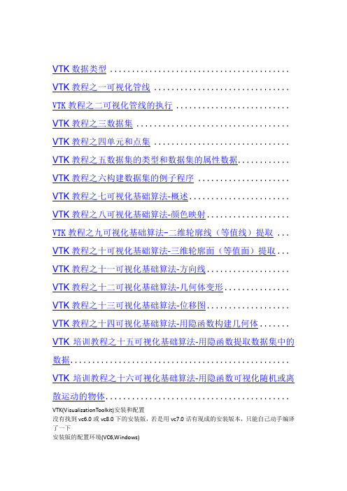
VTK数据类型 ......................................... VTK教程之一可视化管线 ............................... VTK教程之二可视化管线的执行 .......................... VTK教程之三数据集 ................................... VTK教程之四单元和点集 ............................... VTK教程之五数据集的类型和数据集的属性数据............ VTK教程之六构建数据集的例子程序 ..................... VTK教程之七可视化基础算法-概述....................... VTK教程之八可视化基础算法-颜色映射................... VTK教程之九可视化基础算法-二维轮廓线(等值线)提取 ... VTK教程之十可视化基础算法-三维轮廓面(等值面)提取... VTK教程之十一可视化基础算法-方向线................... VTK教程之十二可视化基础算法-几何体变形............... VTK教程之十三可视化基础算法-位移图................... VTK教程之十四可视化基础算法-用隐函数构建几何体....... VTK培训教程之十五可视化基础算法-用隐函数提取数据集中的数据.................................................. VTK培训教程之十六可视化基础算法-用隐函数可视化随机或离散运动的物体..........................................VTK(VisualizationToolkit)安装和配置没有找到vc6.0或vc8.0下的安装版,若是用vc7.0话有现成的安装版本,只能自己动手编译了一下安装版的配置环境(VC6,Windows)1.??????必须要下载的东西,VC6已经装好为前提:vtk-5.0.4-win32.exe安装程序的Download源程序数据2.??????安装vtk-5.0.4-win32.exe在D:\ProgramFiles\VTK5.0,解压到D:\ProgramFiles\VTK5.0\vtk-5.0.4,到D:\ProgramFiles\VTK5.0\vtkdata-5.0.43.??????用cmake编译到D:\ProgramFiles\VTK5.0\bin下,(这一步花了我不少时间,每次cmake 编译到一定量就死掉,不知道什么原因,编译了不下10次终于成功)4.??????参数设置,几个关键参数要注意;vtk_use_guisupport,打开它,才能选vtk_use_mfc,再configure;vtk_data_root:目的是告诉cmake,vtk需要的数据都在哪里,我们的数据在D:\ProgramFiles\VTK5.0\vtkdata-5.0.4build_examples:就是询问是否编译vtk中的例子,我第一次的时候选上了,结果编译了2个小时的例子还没编译完,所以我后来选了off。
Autodesk 2012 产品安装指南说明书

Installing Autodesk 2012 Products:Preparing for InstallationTranscriptReviewing DocumentationBefore you begin your installation, I recommend you review the documentation that is available via the Autodesk product installer.The installation help link will take you to a page giving you access to system re-quirements, installation help, the Autodesk network administrators guide and li-censing guide, as well as links to troubleshooting support pages for the different Autodesk products that you're installing.The system requirements link will take you to the Autodesk Services and Support page where you can check the system requirements for each of the Autodesk 2012 products you are installing. Using this information, verify that your computer meets the minimum system requirements for the Autodesk product being installed. This includes, minimum RAM, minimum free disk space and supported operating sys-tem. If your system doesn’t meet these requirements, problems can occur, both within AutoCAD and at the operating system level.The installation and deployment FAQ will take you to a page where you can ac-cess PDF files of the products installation help and the Autodesk licensing guide, and network administrators guide.The installation help guide provides an overview of the installation steps for each of the Autodesk products being installed, as well as answers to frequently asked questions. I recommend you familiarize yourself with the installation process before you begin installing. Many of the questions that we are asked in product support are already addressed in the installation help documentation.And lastly, I always recommend reviewing the readme file for each Autodesk product being installed. The readme file often contains information relating to in-stallation as well as late-breaking information that may not have made it into thefinal documentation.It's worth taking the time to review all these documents before you begin.Choosing a LanguageIf you’re a subscription customer and you’re planning on installing in a different or additional language, now would be a good time to download that language pack so it is ready to use when you begin the installation.Login to the Subscription Center and select “Get Y our Upgrade”. From there navigate to the product you're looking for – in this case I'll use AutoCAD Electrical 2012 – locate the particular language pack you need and download it.Some products may not have multiple languages available at the time of product release but additional language packs may be available later for Subscription cus-tomers.Once the download is completed, launch the executable, pick the install button and let it extract itself to the default location. Once extracted, the language pack MSI file will be ready for you to add when you run the installer.Getting the Server Host NameIf you will be installing a network licensed product, you will need to know the host name of the server (or servers) that will be running the Autodesk Network Li-cense Manager. If you don’t know the host name, there are a couple of ways to find it.One way is to open a Windows command prompt on the system running the Network License Manager and enter ipconfig /all at the command prompt.This screen will contain a lot of information but all you’re looking for at this point is the Host Name.If the server is already running the Autodesk Network License Manager, there is another way to find the Host name. On the server, run the LMTOOLS utility and switch to the System Settings tab. On this tab, you can see the host name of the server. Use either of these methods to get this information.If you have a Single Server Model, you only need the host name of the one server.If you have a Distributed Server Model, you need the host name of the master server and each server in the distributed pool.And if you have a Redundant Server Model, you’ll need to know the host name of each of the three servers that form the redundant server pool.Locating Y our Serial Number and Product KeyOne important step in preparing for installation is to locate the serial number and product key for the Autodesk product you are installing; you will be prompted for this information during the installation process. The serial number and product key can be found in a variety of locations, depending on how you obtained your Autodesk product.If you have physical media, you’ll see the serial number and product key printed on the label of the box. In this example I'm showing you the label from an Auto-desk Education Master Suite for 2011 but the location and format will be similar for the 2012 products. So, if you are installing from a DVD or USB key, the first place to look for this information is on the product packaging.If you’re a Subscription Customer, you can find this information in the “Contract Administration” section of the Subscription Center. Log into the Subscription Cen-ter, click “Contract Administration” and “Coverage Report”. Once you're looking at the Subscription Coverage Reports, pick your contract number and you will see your serial number and product keys listed under the “Products” section.If you participate in the Autodesk Education Community, you can find this in-formation by logging in and locating the product in question. If you have not al-ready downloaded the product, picking the download button will start the down-load and will display the products serial number and product key. If you have al-ready downloaded the product and just need to know the serial number and prod-uct key, pick the “Get Serial” button for your product to have it display this informa-tion.And finally, if you ordered your product using the online Autodesk store, the se-rial number and product key will be provided in the “Order Details” confirmation screen after the purchase, as well as the subsequent “Thank Y ou” e-mail that you will receive after the purchase process is complete.Preparing your systemUnderstanding Administrative Permission RequirementsThe next step in preparing your system for installation is to confirm your admin-istrative permissions. In order to install an Autodesk 2012 product, you must have administrative rights. Y ou don't have to have domain administrator permissions, but you do need administrative rights in order to do the installation. If you have ques-tions about this, see your system administrator for more information.Installing .NET 4.0Many of the Autodesk 2012 products require the installation of Microsoft .NET 4.0. In most cases, .NET 4.0 will automatically be installed by the Autodesk in-staller however there can be conditions where the Autodesk installer is unable to install .NET 4 and the installation process will automatically be terminated so that it can be installed manually.To ensure that the Autodesk product installation is not interrupted by .NET in-stallation requirements, we strongly recommend manually installing Microsoft .NET 4.0 before beginning installation of your Autodesk 2012 product.Microsoft .NET 4.0 is available in your Autodesk 2012 product media in the fol-lowing location:\3rdParty\NET\4\wcu\dotNetFramework\Reboot firstAfter .NET 4.0 has been installed, you must reboot your computer. Y ou should really do this even if you are not prompted to reboot.Restarting your system before installation helps ensure that any pending operat-ing system updates get applied before you starting installing your Autodesk 2012 products.Turn off virus-checking softwareMake sure you turn off any virus checking software running on your system be-fore you begin installing. Most virus software does real-time checks of files as they're being added to your system. Not only can it slow down the installation process, but it can actually introduce corruption. So make sure that your virus checking software is turned off before you install, and make sure you turn it back on when you're complete.Close all running applicationsAnd the final step, before beginning installation, is to close all applications that are currently running on your system. Some applications—Microsoft Outlook, for example—can interfere with the installation process. So, before you begin install-ing, it's just a good idea to shut down other applications that are running.Copyright © 2011 Autodesk, Inc.Reference Video Series:2012:Preparing for installation of Autodesk products and suites。
vtk 遍历坐标系-概述说明以及解释
vtk 遍历坐标系-概述说明以及解释1.引言1.1 概述VTK(Visualization Toolkit)是一款用于处理和可视化科学数据的开源软件库。
它包含了一系列的算法和工具,能够帮助用户创建复杂的三维可视化效果,用于各种领域的科学研究和工程应用。
VTK具有强大的功能和灵活性,可以处理各种不同的数据类型,包括结构化网格、非结构化网格和图像数据等。
通过VTK,用户可以实现各种数据可视化和分析的需求,从而更好地理解和解释数据。
本文将介绍如何利用VTK库中的功能来遍历坐标系。
我们将讨论不同的坐标系遍历方法,在三维空间中获取坐标系的各个点,并进行可视化展示。
通过本文的阐述,读者将能够深入了解VTK库的功能和使用方法,以及如何利用它来进行坐标系的遍历和处理。
1.2 文章结构本文将首先介绍VTK的基本概念和相关知识,包括VTK的特点和应用领域。
然后探讨如何在VTK中遍历坐标系的方法,包括基本的实现步骤和具体的代码示例。
最后对整篇文章进行总结,回顾讨论的重点和收获,同时对未来的研究方向和发展趋势进行展望。
通过本文的阐述,读者将能够深入了解VTK在坐标系遍历方面的应用和意义,为进一步研究和实践提供有益的参考和指导。
1.3 目的本文的主要目的是介绍使用VTK进行坐标系的遍历方法。
通过清晰地介绍VTK库的基本概念和坐标系遍历方法,读者可以更好地理解VTK的工作原理和应用场景。
希望通过本文的介绍,读者能够掌握如何在VTK 中实现对坐标系的遍历操作,并学会如何利用VTK库来处理和展示复杂的数据集。
同时,本文还将展望VTK在未来的发展方向,为读者提供更多关于VTK的学习资源和信息。
通过本文的阅读,读者可以深入了解VTK库,更好地应用VTK进行科学可视化和数据处理。
2.正文2.1 VTK介绍VTK(Visualization Toolkit)是一款开源的跨平台科学可视化工具库,用于创建三维图形、图像处理和可视化等方面的应用程序。
vtktextrepresentation -回复

vtktextrepresentation -回复关于VTK文本表示(VTK Text Representation)的详细解读VTK(可视化工具包,Visualization Toolkit)是一个强大的开源软件库,能够用于完成数据可视化和图形处理任务。
在VTK中,文本表示(Text Representation)是一个重要的概念,常用于将文本信息呈现在3D场景或2D视图中。
本文将一步一步回答关于VTK文本表示的问题,并深入解读其使用方法以及相关的技术细节。
1. 什么是VTK文本表示?VTK文本表示是应用于VTK中的一种方法,用于将文本信息可视化呈现。
它可以将文本数据转换为可在3D场景或2D视图中显示的形式。
2. VTK文本表示的应用领域有哪些?VTK文本表示在多种领域都得到了广泛应用。
其中包括但不限于科学可视化、工程应用、医学影像处理以及计算机图形学研究等领域。
通过将文本信息可视化,可以更加直观地展示数据并进行交互式分析。
3. 如何使用VTK进行文本表示?使用VTK进行文本表示通常需要以下几个步骤:步骤1:导入相关的VTK库文件在编写代码之前,需要引入相关的VTK库文件。
这些库文件通常包含在VTK的安装包中,并通过指定路径进行导入。
步骤2:创建VTK文本表示对象使用VTK的相关类和函数,创建一个VTK文本表示对象。
这个对象将用于存储和处理文本数据。
步骤3:设置文本内容和属性通过修改VTK文本表示对象的属性,可以设置文本的内容、字体、颜色、位置、大小等属性。
这些属性将决定文本在可视化过程中的呈现方式。
步骤4:将文本表示对象添加到场景中将文本表示对象添加到VTK场景中的合适位置。
这样做可以将文本与其他可视化对象进行组合,并使其在3D场景或2D视图中显示出来。
步骤5:显示和交互文本表示最后,使用VTK提供的绘制函数或渲染器,将文本表示显示在屏幕上。
用户可以通过交互式操作来控制文本的显示和交互行为。
VTK入门及应用案例

VTK入门及应用案例目录前言第一章安装VTK1.1 获取安装资源1.2 安装步骤1.3 测试安装结果第二章VTK快速上手——直接学例子2.1 运行几个简单VTK例子2.2 与窗口交互2.3 视图2.3.1 总览2.3.2 简单操作2.3.3 模型变换2.3.4 投影变换2.3.5 视口变换2.4 光照2.5 角色2.6 组装2.7 获取数据源2.8 纹理2.9 标注2.10 挑选2.11 过滤数据第三章VTK的算法和可视化技术3.1 VTK使用的算法介绍3.1.1 梯度算法3.1.2 矢量算法3.1.3 张量算法3.1.4 建模算法3.2 VTK的编程模式3.2.1 泛型编程3.2.1 模板化3.3 VTK的编程语言3.3.1 使用Tcl/Tk编程3.3.2 使用C++编程3.3.3 使用Java编程3.3.4 使用Python编程3.4 VTK的可视化技术3.4.1 可视化VTK数据序列3.4.2 可视化多边形数据3.4.3 可视化结构型网格3.4.4 可视化直线型网格3.4.5 可视化非结构型网格第四章VTK在图像处理方面的应用4.1 图像和体数据4.1.1 2D画布源图像4.1.2 3D椭圆源图像4.1.3 高斯图像源4.1.4 网格图像源4.1.5 噪声图像源4.1.6 正弦曲线源4.2 图像处理算法4.2.1 图像恢复4.2.2 图像平滑4.2.3 图像增强4.2.4 图像分割4.2.5 图像配准4.3 VTK在医学图像处理的应用4.3.1 DICOM图像数据及其格式转换4.3.2 ROI的勾画4.3.3 多模态图像配准与融合4.3.4 三维重建技术1)面绘制2)体绘制第五章VTK和ITK联合使用5.1 ITK简介5.2 ITK的安装5.2.1 获取安装资源5.2.2 安装步骤5.2.3 测试安装结果5.3 VTK和ITK的混合使用5.3.1 创建一个新目录5.3.2 编写一个CmakeLists.txt和myProject.cxx文件5.3.3 配置CMake5.3.4 编译和运行5.4 基于VTK和ITK的软件介绍5.4.1 3D Slicer5.4.2 IGSTK5.4.3 VolView第一章安装VTK和ITK关于VTK的安装,我看过书上的介绍,也查阅过网上的资料,按照这些说明,确实成功安装了VTK,但在安装过程中,也产生了一些疑问。
10KV开关柜技术要求
10KV开关柜技术要求10KV开关柜技术要求1 总则本技术要求适⽤于 10kV⾦属铠装封闭型移开式中置柜。
投标者须仔细阅读包括本技术规范书在内的招标⽂件中的所有条款,投标者提供货物的技术规范应符合投标⽂件所规定的要求。
投标者应⽣产过多批次符合招标⽂件所规定要求的产品,并已安全⽆故障运⾏三年以上。
投标者所提供的产品,其⽣产⼚家应具备相应产品的型式试验合格证,产品鉴定证书,型号使⽤证书,具有合法的⽣产许可资格。
1.1 标准合同设备应适⽤以下最新版的国家标准:GB311.1 ⾼压输变电设备的绝缘配合GB311.2-311.6 ⾼电压试验技术GB5582 ⾼压电⼒设备外绝缘污秽等级GB11022 ⾼压开关备通⽤技术条件GB1984 交流⾼压断路器GB1985 交流⾼压隔离开关和接地开关GB1207 电压互感器GB1208 电流互感器GB11032 交流⽆间隙⾦属氧化物避雷器GB8287 ⾼压⽀柱瓷绝缘⼦GB/T16927.1 ⾼压试验技术GB7354 局部放电测量DL/T404 户内交流⾼压开关柜订货技术条件DL/T593 ⾼压开关设备的共⽤订货技术导则DL403 10-35千伏户内⾼压真空断路器订货技术条件以上标准有不⼀致处以标准较⾼者为准。
1.2 投标书中应提供的资料投标者应在投标书中提供下列技术⽂件资料:1.2.1产品两部鉴定证书1.2.2 产品型号使⽤证书1.2.3 技术数据表和有关技术资料.1.2.4 型式试验报告1.2.5 同类设备的成功供货记录(具有设备简要参数、安装地点名称、投运时间、运⾏情况的记录)。
1.2.6 与评标有关的其他技术⽂件资料1.3 备品备件投标商应提供随设备配备的备品备件,并列⼊附录1。
1.4 技术⽂件为满⾜施⼯图设计需要,中标商在签订合同后向买⽅和设计部门提供下列技术⽂件资料。
1.4.1 外形尺⼨图及有关说明1.4.1.1 图中应标明组装后⾼压开关柜的外形尺⼨,设备的重⼼位置与总重量、固有频率。
vtk距离测量 科学计数法
VTK距离测量:科学计数法探索引言VTK(Visualization Toolkit)是一个强大的开源软件包,专门用于可视化和图形处理。
它提供了一系列丰富的功能,包括距离测量等操作。
本文将深入探讨VTK中的距离测量方法,并结合科学计数法,解释其应用和意义。
1. VTK距离测量的基础概念1.1 定义距离测量是计算两个点、两个对象或两个几何结构之间的距离或相似度的过程。
在VTK中,距离测量涉及到点之间的空间距离计算,是一项重要的图形处理任务。
1.2 科学计数法的介绍科学计数法是一种用于表示大数字或小数字的方法,特别适用于计算机科学和科学研究领域。
它通过将一个数表示成Mx10^n的形式,其中M是范围在1到10之间的数字,而n是一个整数,表示底数10的指数。
2. VTK中的距离测量方法2.1 欧几里得距离欧几里得距离是最常用的距离测量方法,用于衡量两个点之间的直线距离。
在VTK 中,通过计算点的坐标差的平方和的平方根,可以得到欧几里得距离。
2.2 曼哈顿距离曼哈顿距离是另一种常见的距离测量方法,也被称为城市街区距离。
它衡量的是两点之间在直角坐标系中沿轴的距离总和。
VTK中的曼哈顿距离计算公式可表示为|x1-x2| + |y1-y2| + |z1-z2|。
2.3 马哈拉诺比斯距离马哈拉诺比斯距离是一种衡量两个点之间距离的统计指标,可以同时考虑各个维度的变异性。
它在VTK中的计算涉及到将数据转换为协方差矩阵,并通过特征值分解得到距离。
3. 应用和意义3.1 三维重建距离测量在三维重建领域中具有广泛的应用。
在医学影像处理中,VTK的距离测量方法可以用于计算病灶之间的距离,从而帮助医生进行诊断和治疗决策。
3.2 数据聚类距离测量也在数据聚类领域发挥着重要作用。
通过计算数据点之间的距离,可以将它们分组成不同的簇,有助于寻找数据中的模式和关联性。
VTK中的距离测量方法为数据聚类提供了有力的工具。
3.3 科学研究科学研究中经常需要处理大量的数值数据,而科学计数法在这方面具有重要的作用。
- 1、下载文档前请自行甄别文档内容的完整性,平台不提供额外的编辑、内容补充、找答案等附加服务。
- 2、"仅部分预览"的文档,不可在线预览部分如存在完整性等问题,可反馈申请退款(可完整预览的文档不适用该条件!)。
- 3、如文档侵犯您的权益,请联系客服反馈,我们会尽快为您处理(人工客服工作时间:9:00-18:30)。
一、产品特点概述VTK-12(G)型弹簧式户内高压真空断路器(以下简称断路器)是专门为海拔高于1000m 的地区,12kV电力系统开发的户内专用开关设备,可作为电网设备、工矿企业动力设备的保护和控制单元。
正是安装位置高海拔环境对电气产品的特殊要求,与普通断路器相比,VTK-12(G)具备显着特点,主要表现在:二、型号的表达方式-□山东泰开真空开关额定短路开断电流kA额定电压kV三、产品依据标准断路器符合GB1984-2003《交流高压断路器》、JB3855-2008《3.6~40.5kV户内交流高压真空断路器》、DL/T403-2000《12kV~40.5kV高压真空断路器订货技术条件》标准要求,并符合IEC56(87出版物)的相关要求。
四、使用环境条件a)环境温度最高温度:+40℃最低温度:-15℃b)环境湿度日平均相对湿度:95%月平均相对湿度:90%日平均蒸气压:2.2×10MPa月平均蒸气压:1.8×10MPad)地震烈度不超过8度;e)使用场所无滴水,无易燃和爆炸危险,无化学腐蚀性气体以及无剧烈震动。
五、产品结构及工作原理5.1本体结构VTK-12(G)断路器主体部分采用固体绝缘结构,利用先进的环氧固封技术,将真空灭弧室、主导电回路、绝缘支撑等有机的结合成为一个集成固封极柱。
从根本上解决了真空断路器的环境耐受问题。
5.2操动机构部分5.2.1弹簧操动机构(参见图1、图2)操动机构为弹簧储能操动机构,断路器框架内装有合闸单元,由一个或数个脱扣电磁铁组成的分闸单元,辅助开关,指示装置等部件;前方设有合、分按钮,手动储能操作孔,弹簧储能状态指示牌,合分指示牌等。
5.2.1.1储能断路器合闸所需能量由合闸弹簧储能提供。
储能既可由外部电源驱动电机完成,也可以使用储能手柄完成。
储能操作:由固定在框架上的储能电机16进行,或者将储能手柄插入手动储能孔中逆时针摇动进行。
电动储能时由电机输出轴15带动链轮传动系统(14,18,23),手动储能时通过蜗轮、蜗杆(11,13)带动链轮传动系统。
链轮23转动时,销2推动轮6上的滑块4使储能轴7跟随转动并通过拐臂5和21拉伸合闸弹簧进行储能。
到达储能位置时,框架的限位杆3压下滑块4使储能轴与链轮传动系统脱开,储能保持挚子9顶住滚轮8保持储能位置,同时储能轴上连板24带动储能指示牌25翻转显示“已储能”标记并切换微动开关切断储能电机供电电源,此时断路器处于合闸准备状态。
5.2.1.2合闸在合闸操作中,无论用手按下“合闸”按钮或远方操作使合闸电磁铁动作,均可使储能保持轴19转动,使挚子9松开滚轮8,合闸弹簧收缩同时通过拐臂5、21使储能轴7和轴上的凸轮22转动,凸轮又驱动连杆机构(32,34,35,36,37)带动绝缘拉杆31和动触头进入合闸位置,并压缩触头弹簧30,保持触头所需接触压力。
合闸动作完成后合闸保持挚子36与半轴39保持合闸位置,同时储能指示牌、储能微动开关复位,电机供电回路接通。
若外接电源也接通则再次进入储能状态,连杆42拉动合/分指示牌,显示出“合”的标记,传动连杆拉动主辅助开关切换。
注:当断路器已处于合闸状态或选用闭锁装置而未使闭锁装置解锁及手车式断路器在推进推出过程中,均不能进行合闸操作。
既可按“分闸”按钮,也可靠接通外部电源使分闸脱扣电磁铁或过流脱扣电磁铁动作使合闸保持挚子38与半轴41解锁而实现分闸操作。
由触头弹簧和分闸簧35存储的能量使灭弧室28动静触头分离。
在分闸过程后段,由液压缓冲器吸收分闸过程剩余能量并限定分闸位置。
由连杆44拉动合/分指示牌显示出“分”标记,同时拉动计数器,实现计数器计数,由传动连杆拉动主辅助开关切换。
5.2.1.4弹簧机构防误联锁断路器能提供完善的防误操作功能。
(参见图3、图4)A断路器合闸操作完成后,合闸联锁弯板1向下运动扣住合闸保持轴上的合闸弯板2,在断路器未分闸时将不能再次合闸。
B断路器在合闸结束后,如合闸电信号未及时去除,断路器内部防跳控制回路将切断合闸回路防止多次重合闸。
(可选)C手车式断路器在未到试验位置或工作位置时,由联锁弯板3扣住合闸弯板2上的销4,同时切断合闸回路,防止断路器处于合闸状态进入负荷区。
D手车式断路器在工作位置或试验位置合闸后,由滚轮5压推进机构锁板6,手车将无法移动,防止在合闸状态推进或拉出负荷区(图4)E如果选用电气合闸闭锁,在未使闭锁装置解锁情况下阻止合闸操作。
注:合闸闭锁装置功率为2.7W,工作电压范围为0.65~1.1倍额定电压。
图11储能到位切换用微动开关7储能轴13手动储能传动蜗轮19储能保持轴2销8滚轮14电机传动链轮20闭锁电磁铁3限位杆9储能保持挚子15电机输出轴21拐臂4滑块10合闸弹簧16储能电机22凸轮5拐臂储能传动轮11手动储能蜗杆17联锁传动弯板23储能传动链轮6储能传动轮12合闸电磁铁18传动链条24连板图225储能指示牌30蝶簧35主轴传动拐臂40手动分闸顶杆26散热架31绝缘拉杆36分闸挚子41凸轮27上出线端32传动拐臂37连扳42分合指示牌连扳28固封极柱33分闸弹簧38分闸电磁铁29下出线端34传动连板传动拐臂39半轴注:当断路器已处于合闸状态或选用闭锁装置而未使闭锁装置解锁及手车式断路器在推进或摇3图4六、VTK-12(G)系列户内高压真空断路器6.1主要技术参数6.2机械参数6.3外形尺寸mm底盘车行程为300mm七、安装、调试7.1断路器从包装箱中起吊时,挂钩应挂在断路器上有明显标识的起吊孔处,搬移时不得使上、下出线臂受力,同时不应让断路器受到较大的冲击振动。
注:在正式进柜操作前,请按要求去除起吊装置。
7.2断路器出厂前已经过严格的出厂检验,参数均符合技术要求。
一次回路通电前必须做以下准备工作。
检查断路器有无损坏,如有损坏请停止使用;a 、 清除脏污,尤其是绝缘表面,由于运输过程或存储过程造成的脏污会影响产品的绝缘性能。
b 、 用手动方式操作断路器进行储能、合闸和分闸,观察储能状态、分合位置指示是否正常。
c 、 用操作电源操作断路器进行储能、合闸和分闸,观察储能状态、分合位置指示是否正常。
d 、 手车式弹簧机构断路器按如下步骤操作:将推进手柄插入推进孔中,顺时针摇动为推进,逆时针摇动为退出。
推进总行程300mm 。
在分闸状态下,应顺利进入工作位置或试验位置,请中速转动手柄30圈,当听到“嗒”的一声时即为到位(切忌用力过大而损伤推进机构),同时相应位置指示(S8、S9)回路接通。
操作过程可能出现的现象按以上原因检查后,仍有疑问的请与生产厂家联系。
7.3进行工频耐压绝缘试验。
八、维护与保养本公司生产的断路器选用特制滚动轴承,采用特殊表面处理防锈工艺,配用长效润滑脂,在正常使用条件下,10~20年不需检修,但由于使用环境的差异,仍需进行必要的检查、维护工作。
9.1视工作环境在6~12月内应对断路器本体进行适当检查。
在外观检查后,需对设备表面的污秽受潮部分进行清洁,用干布擦拭绝缘件表面,然后用沾有清洗剂的稠布擦去其他污秽物(注意所用清洗剂能适用于塑料或合成塑料材料)。
9.2当断路器长期放置时,可能使断路器活动部分产生阻滞,每年应对断路器进行至少5次的储能及合、分闸操作。
9.3每年应对断路器进行至少1次的绝缘测试以判断断路器真空灭弧室是否漏气或其他外界原因造成绝缘强度的降低。
9.4对于频繁操作场所,应注意严格控制在技术条件规定的操作次数范围内,不能在超出使用寿命后继续使用。
十、订货须知订货时应注明:1、断路器型号、名称、主要技术参数及订货数量。
2、操作电压种类及参数。
3、备品、备件的名称及数量。
十一、随机文件A.产品合格证;B.出厂检验报告;C.安装使用说明书产品说明与图例仅供参考,本公司保留修改权利。
手车式内部电气接线原理图(带闭锁、防跳方案)固定式内部电气接线原理图(带防跳方案)安全注意事项一、注意2、维护时,机械操动机构的所有弹簧必须处于松弛状态,同时断路器应处于分闸状态,"合闸弹簧未储能"标志应可见.3、不要随便移去机构箱面板,不要触摸打开面板机构箱内部.不要触摸极柱装配部分以及绝缘操动杆违章操作会导致严重的人员伤亡.二、警告1、只有完全熟悉本书所有警告,安全条例以及产品维护程序的人员才可以使用维护本设备。
本设备成功和安全的运行取决与正确的搬运,安装,操作以及维护.2、本设备在运行时带有危险电压,以及可以通过远控实现高速运动的机械部件.3、如二次电源没切断,切不可触及线圈及二次终端.违章操作会导致严重的人员伤亡或破坏性损失。
三、危险1、高压!2、接触导电部分会导致死亡或严重人身伤害.3、只有完全熟悉操作手册特别是安全规程的人员才可操作本设备.4、投入使用前,必须参照当地的高压开关柜的安全准则,例如五防标准.断开二次电源然后通过手动关合断路器(真空断路器处于分闸状态"合闸弹簧未储能"标志可见).违章操作会导致严重的人员伤亡和设备损害.四、处置说明:断路器本体具有环境友善性。
相应的材料处置应优先考虑循环使用。
断路器可进行解体处理并符合现行立法对于环保的要求。
它可以当做混合废弃物来处理。
开关设备本体包括以下材料:钢、铜、铝、聚四氟乙烯、环氧浇铸件、玻璃纤维增强塑料其他塑料;用于密封作用的橡胶、陶瓷、润滑剂和油。
