盐分测试笔使用说明书-090224mq翻译-ch审核
EC Testr 11+ 盐分测试说明书(英文)

u臼 n90"lOFF
as¢ key随 怡
Cl°
F key
旷
m~
:芹
2
取 Ψ 挥 照 槲社 憔 甜 乍 燕 撒扌 滞桁
y讧
汀 :ll 口 冖 o=e Voti B● 臼
亍 丨 下 丨 龊 屏
:审 i苫i|[:茁
l佶
:j带 l甘
unm you田 e|hc「 en"虍 d fanqe(Pu.1o orH→
sdu° n ′ Ⅲ d。 rl c控s饴 r铂 o"‘ C″or m甾 ε e'a° 旧 ″ 口 〃rc扣 r″ ‘” mmsu冖n9modb〃 m¢ 夕 ・ (,φ C 幻Vp¢ ″ l″ 0′ ⒒ hc Q仂 rar诙 ,刀 ω|u!io″ ‘刀 o扌 vl・ l” ,0φ Cro σ 肋 汪 而c.es腔 r珈 ° 略 σmrmc剪 a¢ 臼 〃〃,ou p田$H0‘ ″臼
ll旧 扌 mak” cs・ le‘ c抬 c扌 ed
″ msu″ 四 臼冖 ¢ 夕
4 R丨 nse the e丨
ec!【 odc w"h the ca"br扯 丨 on slanda∫ d that y° u|n!cnd!o ca‖ brale and !hen d pthe c edf碉 e n!he other beake∫ w"h same ca|b`akon s!andar0 s″ ∫
you【 app‖ (alon
ura6io咖 cun臼 臼 臼 m
cnjjooa扣 ″ Ji`oim!c臼 jjb扫 ijo"fo`FC乃ε iri亍 ●
肪山 “ {!i-p° 加 扌 m仙 ″″ o刀 hc泊 ” Fr茁sp卸 uu扌 ° ma"call/0‘ 估 a扌 ・ hc `扌 臼淅"F0r而 a饷 n sh” 由诏 旧lllc maf[眈e|y nakhcs 「 llc tole子¤ n¢ ″刀 eo± 珀 %研 夕 mf m胁 rallp刀 ‘ 扫″ da〃 「ck‘ 抬r‘ ho略 ermr田 6臼 夕 e fr〃 亻 四″lr,/0臼 仙″扫 a珀 山 油刀1ohosF ωndt妖|yr,o ouudc joc o° 妇 ra刀 cc‘ a呷 "仂 ″ 讪σ″c$lWC研 DFC″ ″ 〃 o″ avV臼 协旧而n.讪 rlll9a〃 oF ”臼l+lsh” c妞 〃 m¢ n加 昭 ‘ 泊 ”
水抗挥发性盐度测试笔规格及操作说明书
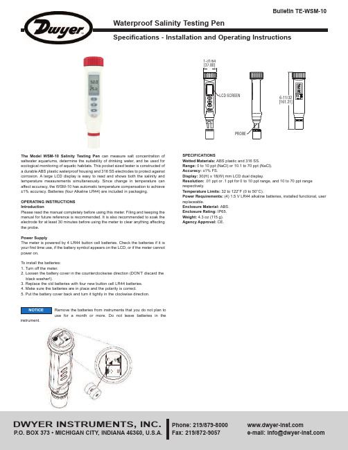
Specifications - Installation and Operating InstructionsBulletin TE-WSM-10- C or F is the unit of the liquid temperature.- is the battery low icon.KeypadOperation1. Remove the probe cover from the meter to expose the electrode.2. Press to power on the meter. The LCD will display parameters (ex: tnr, tCo, tds,rAn) in turns and then it will enter normal display.accuracy. Alternatively, you can manually select the ranges. For example, if you prefer the meter to display a reading such as .50 mS instead of 500 uS, you press for more than 2 seconds.measurement mode. When the reading is stable, the unit will stop flashing.10. Press to freeze current readings. The text “Hold” will appear on the LCD. Pressagain to release.11. Turn off the meter by pressing .12. Make sure your electrode is clean and store it carefully. Before storage, rinse itcarefully in de-ionized water and store dry with the cap. Remember the storage temperature limits. For more information, see the maintenance section.13. Air bubbles can easily adhere around the gap between the electrode and theTo disable the auto power off:Before power on, press + simultaneously until an “n” appears on the screen. Then, release the keys to return to normal mode.The advanced setup mode lets you customize your meter’s preferences and defaults. To change the parameters, you can press for more than 2 seconds. You will enter setup mode when the meter is in measurement mode.1. When the meter is in measurement mode, press f for more than 2 seconds toenter setup mode.2. Press , , or to select P1.0.3. Press momentarily again to enter unit setting.4. Press or to select C or F.5. Press momentarily to confirm the unit, or press it for more than 2 seconds toreturn to P1.0 without saving.6. While in P1.0, press for more than 2 seconds to return to measurement mode. P3.0 Reset Meter (rSt)When you decide to reset the meter, all parameters will be reset to factory default values, including the calibration information.1. In P3.0, press momentarily to enter P3.1.2. Press or to select Y or N.3. Press momentarily to confirm the state and return to P3.0, or press it for morethan 2 seconds to return to P3.0 without confirming the P3.1 value.P4.0 Review Calibration Information (CAL)In P3.0, press or to select P4.0.P4.1 Range 1 Calibration Informationpress momentarilyconcentration. If the meter is not yet calibrated, “---”will display on the LCD.In P4.1 or P4.2, press momentarily to confirm the state and return to P4.0. In P1.0, P2.0, P3.0, P4.0, you can press for more than 2 seconds to return to1. Turn off the meter and stay in normal measurement mode.2. Press or for more than 2 seconds to select the range.(Default)temperature.7. Press for more than 2 seconds to begin the calibration. The SALT value willblink on the LCD.8. Press the or to adjust the value to match the value to the calibrationstandard. You can adjust the SALT reading up to ±30% from the detected value.9. When the “CAL” stops blinking, you can press to confirm the value. The meterwill switch back to SALT measurement mode. If “CAL” always blinks, check theThe text P1.1, P1.2, P1.3, P2.1, P3.1 will not displayLCD.NOTICE。
盐度测量仪使用方法

盐度测量仪使用方法
使用盐度测量仪的方法如下:
1. 首先,将盐度测量仪连接到电源,确保设备正常工作。
2. 将盐度测量仪的电极部分放入待测液体中。
注意电极应完全浸入液体中,并确保液体不会溅出浸湿设备外壳。
3. 等待一段时间,直到测量仪稳定下来并显示一个读数。
这可能需要几秒钟或几分钟,具体时间取决于测量仪的型号和待测液体的性质。
4. 阅读盐度测量仪上显示的盐度值。
不同的设备可能有不同的读数显示方式,有些设备可能是数字显示,有些可能是指针指示或者显示LED灯等。
5. 在使用后,及时清洁和保养盐度测量仪,以确保其准确度和使用寿命。
根据设备的说明书,正确地清洗和存放设备,例如用干净的水冲洗电极并用干布擦干。
注意事项:
1. 需要使用盐度测量仪时,确保设备没有损坏或损坏的电极,以免影响测量结果的准确性。
2. 在使用盐度测量仪时,确保液体环境的温度稳定,并避免过高或过低的温度对测量结果产生影响。
3. 根据测量要求,选择正确的盐度测量仪和相应的电极类型,以确保适用于待测液体的范围和精度。
4. 在使用盐度测量仪时,确保设备的工作环境清洁,避免灰尘和杂质对测量结果的干扰。
5. 如果有特殊要求或需要更高的精度,可以校准盐度测量仪。
按照设备的说明书或使用手册上的校准方法进行校准操作。
以上是一般盐度测量仪的使用方法,具体操作步骤可能因设备类型和型号的不同而有所不同,请根据具体设备的使用说明进行操作。
盐分检测套装使用操作方法

盐分检测套装使用操作方法
A 选择铁的表面上一小段面积来作盐份测试,要保证这一段表面干燥,并没有灰尘、未被破坏,这样贴纸才能完全贴在被测物体表面上,盐份测试样品可以随意放置,垂直,水平都可以。
最好多测几处被污染的表面。
B 撕掉盐份贴纸上面的保护膜,把它紧紧地贴在被测物体的表面。
C 取3或5ml经过0校正的水注入盐份贴纸上。
在注入水之前用空的注射器及出贴纸样品上的空气。
D 用注射器来回移动稀释测试表面的盐份。
这个操作过程需要持续3-5分钟,每分钟注射器来回抽动2-4次。
E 完成后,用注射器吸掉所有的水份,再将水注入25ml的杯中,
F 杯子中的水应该有15ml。
G 测量杯子中的水的电导率并记录下测量值。
H 计算一下测量值(操作中G的测量值)与零校正时的值之间的误差。
(S测量值-S零校正值)
可溶性盐的表面密度/污染物(S)用mg/m2 是
S=6×(样品值-零校正值)
(所有盐都可以当做是氯化钠)
校品值和零校正值是S每厘米
I 倒掉污染过的水并水蒸馏水清洗所有部件。
清洗是进行下一次测量时最重要的一个步骤。
J 在测试以后要完全清洗掉仪器表面的盐份样品。
盐度计的操作使用
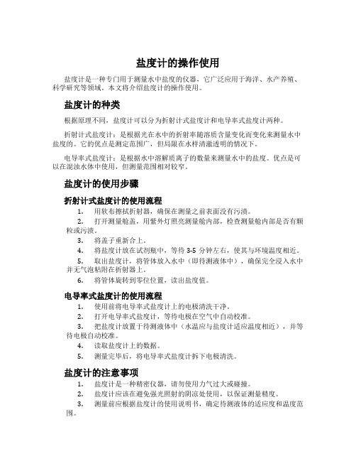
盐度计的操作使用盐度计是一种专门用于测量水中盐度的仪器,它广泛应用于海洋、水产养殖、科学研究等领域。
本文将介绍盐度计的操作使用。
盐度计的种类根据原理不同,盐度计可以分为折射计式盐度计和电导率式盐度计两种。
折射计式盐度计:是根据光在水中的折射率随溶质含量变化而变化来测量水中盐度的。
它的优点是测定范围广,但局限在水样清澈透明的情况下。
电导率式盐度计:是根据水中溶解质离子的数量来测量水中的盐度。
优点是可以在混浊水体中使用,但测量范围相对较窄。
盐度计的使用步骤折射计式盐度计的使用流程1.用软布擦拭折射器,确保在测量之前表面没有污渍。
2.打开测量舱盖,用紫外灯照亮测量舱内部,检查测量舱内部是否有颗粒或污渍。
3.将盖子重新合上。
4.将盐度计放在试剂瓶中,等待3-5分钟左右,使其与环境温度相近。
5.取出盐度计,将管体放入水中(即待测液体中),确保完全浸入水中并无气泡粘附在折射器上。
6.将管体旋转到零位位置,读出盐度值。
电导率式盐度计的使用流程1.使用前将电导率式盐度计上的电极清洗干净。
2.打开电导率式盐度计,等待电极在空气中自动校准。
3.把盐度计放置于待测液体中(水温应与盐度计适应温度相近),并等待电极自动校准。
4.读取盐度计上的数据。
5.测量完毕后,将电导率式盐度计拆下电极清洗。
盐度计的注意事项1.盐度计是一种精密仪器,请勿使用力气过大或碰撞。
2.盐度计应该在避免强光照射的阴凉处使用,以保证测量精度。
3.测量前应根据盐度计的使用说明书,确定待测液体的适应度和温度范围。
4.盐度计的使用需要严格按照使用说明操作,否则会影响测量精度。
5.盐度计的存放需要放在干燥、避光的环境中。
长期不用的盐度计应该放在盐度计箱中。
结论通过本文的介绍,相信大家对盐度计的操作使用有了更深入的了解。
在使用盐度计时,我们要注意细节,避免因小失大,同时也要掌握好日常维护保养工作。
Elcometer138盐分测试套装使用说明书

易高Elcometer138盐分测试套装操作指南1.1Elcometer138包装清单:●一盒25片Elcometer Bresle盐分贴片,●250ml纯水置于透明塑料瓶中,●3个5ml注射器,●3个钝针头,●30ml塑料大口杯,●Elcometer138电导率计,●2节CR2032锂电池,●14ml标准瓶校准溶液(1.41mS/cm),●14ml瓶装润湿溶液,●提箱和操作手册2.测试步骤:ISO8502-6/ISO8502-092.1使用前1.校正电导率计——详见15页4.4“单点校准”2.测试过程中需戴好手套。
此测试极其灵敏;在提取可溶盐过程中需戴好医用手套(乳胶手套)或丁腈手套从而避免污染其表面。
2.2步骤1.从盐分贴片中心,取出保护包装和泡沫中心;2.在表面贴上盐分贴片,压紧边缘,实现完全密封——确保测试舱中有最少的空气;3.用注射器抽取3ml纯净水;4.通过泡沫边缘,将注射器以30°角度插入盐分贴片中,从而使其穿透泡沫进入由测试表面和橡胶膜形成的测试舱,并注射1.5ml的纯净水到盐分贴片中;不要移动注射器。
如有需要可使针头弯曲以便于操作。
5.轻轻调整一下针头,使盐分贴片中的空气跑出来。
6.将注射器取出,针头朝上轻轻推出里面的空气。
7.再把注射器重新插入盐分贴片,将其余的纯净水注射到盐分贴片里面。
不要移动注射器。
8.过一会儿后(对于无凹痕的喷砂除锈区域,10分钟即符合要求),用注射器将盐分贴片里面的水抽取道针管里,然后立即重新注射到贴纸里。
9.重复第8步至少4次,完成抽取/注射的循环。
10.最后尽可能地将盐分贴片中的溶液全部抽取出来。
(4-10步操作中必须确保无溶液损失,若有损失,测试结果将不准确)11.用Elcometer138电导率计测试抽取出来的溶液的电导率值——详见第16页第5部分“测量”。
把溶液样品直接注射到电导率计的测试舱上测试。
测取读数前,使用待测溶液多次冲洗电导率计的测试舱。
盐水电解质检测仪说明书

Free Chlorine Amperometric 4-20mA SensorsSECTION 1THEORY OF OPERATION1.0 FREE CHLORINE DEFINED. Free Chlorine or "freely active chlorine" is defined as the sum of molecular chlorine (Cl 2), hypochlorous acid (HOCl) and hypochlorite ions (OCl -). Molecular chlorine occurs at pH values <pH4. Hypochlorus acid and hypochlorite ions are in pH de-pendent equilibrium with one another as shown in FIG 1. The graph shows % hypochlorous acid on the left of the curve. Hypochlorous acid is a much stronger disinfecting agent (oxidizer) as compared to hypochlorite ions.1.2 SENSOR OPERATING PRINCIPLE. Only hypochlorous acid (HOCl) diffuses through the membrane between the cathode and sample solution. At the applied potential, only hyphochlorous acid is elec-trochemically reduced. HOCl is reduced to chloride ion at the gold cathode. At the same time, the silver anode is oxidized to form silver chloride (AgCl). When the concentration of HOCl at the cathode is dramatically decreased by electrochemical reduction, hypochlorite ion will be transformed into hypochlorous acid , to some extent, by proton transfer. The release of electrons at the cathode and ac-ceptance at the anode creates a current flow, which under constant conditions, is proportional to the free chlorine concentration in the medium outside the sensor. The resulting low current output is then conditioned to 4-20mA current by the sensor's onboard electronic circuitry.SECTION 2FACTORS INFLUENCING THE SENSOR2.0 pH. Free Chlorine (FCL) exists as hypochlorous acid andhypochlorite anion (FIG 1). The acid-base dissociation of FCL has a pKa of approximately 7.5. The FCL sensor responds to hypochlorous acid and hypochlorite anion with different sensitivity. In combination, an increase in pH reduces the measured FCL and decrease in pH increas-es the measured FCL. For the most accurate free chlorine measure-ment, pH compensation is required above pH 6.5. pH compensation for the sensors current (mA) reading is:Real mA = (measured mA – 4)/ compensation factor + 4compensation factor = -0.13*pH*pH + 1.6718*pH - 4.15672.1 Chemical Interferences. The sensors should not be used in water containing surfactants, organic chlorine or stabilizers such as cyanuric acid, chlorine dioxide, ozone or bromine.2.2 FLOW. To acheive reproducible measurements, the (FCL) free chlo-rine sensors require a specified constant flow rate. To avoid complica-tions (such as bubbles), it is best to operate the sensors at a flow rate of 0.2-0.6 gpm ( if using flow cell FC72 or FC70 (old version). Use of a flowmeter is recommended ( FM001- See Section 4.1)SECTION 3SENSOR PREPARATION3.0 FREE CHLORINE SENSOR ASSEMBLY. The Free Chlorine Sensor is shipped with the membrane cap pre-installed andcovered with a cap with water inside to keep the membrane wet. Make sure to keep sensor cap, anode and cathode, away oily or greasy materials. Contact with oil or grease will result in inaccurate measurements. The sensor is also supplied with a 3 oz bottle of refill solution and a syringe and needle tip.NOTE: IF SENSOR WILL BE STORED DRY OUT OF THE FLOW CELL, SHAKE BODY DOWNWARD INTO A SINK TO REMOVE THE FILL SOLUTION. TAKE THE MEMBRANE CAP AND IMMERSE IT IN A CUP OF TAP WATER UNTILL READY TO REUSE. SEE SECTION 10. REPLACE CAP AND ELECTROLYTE BEFORE INSTALLING INTO FLOW CELL (see SECTION 10 for cap and electrolyte change. See SECTION 5 for sensor installation into flow cell).SECTION 4FLOW CELL /FLOW SENSORINSTALLATION4.0 FLOW CELL. To obtain accurate Free Chlorine reading, the Sensor must be installed into the Flow Cell to prevent air bubbles formation on the membrane, proper spacing between the sensor and the installation wall, and laminar flow across the membrane. MAKE SURE SENSOR AND FLOW CELL ARE ORIENTED VERTICALLY OR NO MORE THAN 45 DEG BELOW VERTICAL (FIGURE 2B)4.01. Using two 1/4” NPT Tube fittings, connect the FC72 Flow Cell into your system, noting the inlet (bottom) and outlet (side) orientation. (see FIGURE 2)4.02. Install clamp with rubber backing as shown in FIG. 2A.4.03 Drill 3/8" diameter hole on the panel.4.04 Insert bolt as shown in FIG 2A4.05 On back of panel attach lock washer and nut to secure clamp and flow cell to panel.Ensure flow cell is mounted at 45 deg or higher above horizon-tal as shown in FIG 2b.4.1 FLOW METER. To control flow to the flow cell, a flow meter is recommended. Sensorex supplies model FM001 for this purpose. The FM001provides flow control from 0.1 to 1.0 GPM (0.5 to 4.0 LPM) with 6% accuracy.4.1.1 Install the flow meter and flow cell as shown in FIG 2c. Follow the diagram so that the incoming water is attached to the bottom of the flow meter (where flow adjustment knob is located).6.0 ELECTRICAL INSTALLATION. The sensor produces an ap-proximate output of 4 mA in air and 20mA at the top range of free chlorine output (0-2ppm, 0-5ppm, 0-10ppm).NOTE: The supply voltage to the Sensor must be 12-24 V DC withminimum of 250 mA. Maximum load is 1 Watt. The sensor has 3 wires, red (+) , black (-) and clear (shield). Twist together or solder black and clear if instrument does not have separate ground. If a separate ground is available such as for PLC’s connect clear (shield) to it.Attach the red wire to the power supply positive terminal (+)and the black wire to the PLC or DVM positive (+) terminal. Connect a wire (customer supplied) from the power suppy negative (-) and the PLC or DVM (-). See FIG 3. The Sensor will require several minutes to stabilize after power is supplied to it.7.0 SENSOR CONDITIONING The sensor requires conditioning prior to generating stable values. a. For new Sensors, connect the sensor to power and allowto run overnight (at least 12 hours) before calibration. b. If the Sensor will be un-powered for 2 hours or more, run for 2 hours prior to use. c. If the Sensor's flow will be off for 1 hour or less, run the sensor for at least 1 hour prior to recalibration. c. After membrane/electrolyte replacement, allow the Sensor to run powered overnight (at least 12 hours) before calibration .SECTION 6ELECTRICAL INSTALLATIONSECTION 7SENSOR CONDITIONINGSECTION 5SENSOR INSTALLATION5.0 SENSOR INSTALLATION INTO FLOW CELL. a. First install threaded fitting onto sensor body (remove fitting if pre-installed in flow cell) b. Install snap-ring into groove on sensor body c. Next, slide o-ring onto body of sensor until it reaches bottom of threaded fitting. d. Thread sensor assembly into top of flow cell as shown in FIGURE 2. d. Turn on flow and verify the flow through the Flow Cell is at least 0.2gpm (45 liters/hour and no more than 0.6gpm (135 liters/hour).10.0 ELECTROLYTE SOLUTION REPLACEMENT: Drain and refill the sensor approximately every 2 months.10.1 MEMBRANE CAP REPLACEMENT. If membrane replacement is required, a new cap with preinstalled membrane must be used. Order FCLA-4016 replacement membrane cap and FCLA-4015 refill solution. To change membrane cap (do the following over a sink or washbasin):a) turn sensor upside down with cap facing upward b) rotate cap counter-clockwise to remove (see FIG 10).c) Attached supplied needle to syringe and remove fill solution as shown in FIG 10 & FIG 11.c) fill sensor body with electrolyte using needle and syringe of refill solution (see FIG. 12)d) install a new membrane cap by threading cap onto sensor rotating cap clockwise (opposite of FIG 9)10.2 MEMBRANE CAP/SENSOR CLEANING. Rinse cap with water only. If cap does not clean, replace with new one.SECTION 10SENSOR MAINTENANCE/RECONDITIONINGSECTION 11SENSOR TROUBLESHOOTING11.0 CALIBRATION PROBLEMS a) Sensor output HIGHER than DPD test 1) Run in time too short 2) Membrane cap damaged 3) Interference from water contaminants (see Specifications, "Cross Sensitivity") 4) Cable short circuit or damage 5) pH value less than pH 5.5 b) Sensor output LOWER than DPD test 1) Run in time too short 2) Deposits on Membrane cap 3) Flow rate too low 4) Air bubbles on membrane 5) Surfactants in water 6) pH value more than pH 8.57) no electrolyte in sensor chamberc) Sensor ouput is 4mA (zero ppm) 1) Run in time too short 2) Only bound chlorine present 3) Chlorine content below detection limit 4) Sensor not wired correctly (See SECTION 6.0 of this manual) 5) Defective sensor d) Sensor output UNSTABLE 1) Air bubbles on membrane 2) Membrane damage 3) Pressure fluctuation in sample lineSymptom Possible CauseSolution/Remedy The sensor 1) Run in time too short1) See Sec 7.0 -CONDITIONINGcannot be 2) Membrane cap damaged2) Replace cap - See Sec 10.0 calibrated- 3) Interference from contaminants 3) See SPECIFICATIONS Sec 12 ouput is 4) DPD chemicals bad 4) Use new DPD kitHIGHER than 5) pH value < pH 5.5 5) Increase pH (5.5-8.5) DPD TestSee SPECIFICATIONS Sec 12 6)Temperatue increased since cal6) Match calibration temp.The sensor 1) Run in time too short 1) See Sec 7.0 -CONDITIONING cannot be 2) Deposits on membrane cap 2) Remove deposits or replace calibrated- cap if cleaning ineffective. output is 3) Flow rate too low 3) increase fl ow - See LOWER than SPECIFICATIONS DPD Test 4) Air bubbles on membrane 4) Remove and re-install s ensor to remove bubbles. 5) Surfactants in water 5) Remove surfactants and replace cap. See SEC 10.0 6) pH > pH 8.5 6) Lower pH (5.5-8.5) See SPECIFICATIONS 7) No electrolyte in cap 7) Add new electrolyte, run in sensor and re-calibrate 8) Temperature decreased since cal 8) Increase temp to match cal 9) Organic chlorination agents 9) Use chlorinating agents present in water per DIN 19643 Sensor output 1) Only bound chlorine present 1) Check for Chloramine with is 4mA (0 ppm) NO FREE CHLORINE appropriate DPD test.Replace water/ Rechlorinate. 2) Run in time too short2) See Sec 7.0 -CONDITIONING 3) Chlorine content below limit 3) Add chlorine and repeat calibration4) No electrolyte in cap4) Refi ll electrolyte 5) Sensor electrical connection 5) See SECTION 6.0wrongUnstable output 1) Air bubbles on sensor membrane 1) Tap to remove bubbles from sensor 2) Membrane damaged 2) Replace membrane, run in sensor and recalibrate.3) Non-sensor problem3) check PLC or I/O deviceTROUBLESHOOTING CHARTOperating temperature range: 0-45 degC Maximum operating pressure: 1 bar/14.7 psi/1atm Flow rate minimum: 0.2 gpm (0.75Lpm) Flow rate maximum: 0.6 ppm (2.25Lpm) pH range: 5.5-8.5 Output signal: 4.0+/- 0.2mA in air (zero) 20mA +/- 0.2mA at high range (2, 5 or 10ppm) Power Requirement: 12-24 VDC, 250 mA minimum Cross-Sensitivity: ClO2, ozone, bromine, iodine Chemical Compatibility: up to 50% ethanol/water or up to 50% glycerol/waterOPERATING SPECIFICATIONSSECTION 12SENSOR SPECIFICATION12.0 OPERATING SPECIFICATIONS. Follow all operating specifications, especially for pH and flow rate as noted in the specification tables below.SENSORDimensions: 8.2"L x 1" dia Body Material:Black PVC Membrane Material: polyethersulfone O-ring material: Viton R Cathode: Gold Anode: Silver chloride (AgCl) Cable: 2 -conductor shielded, 10ft (3mtr) tinned wire leadsFLOW CELL Dimensions: 5.58"H x 2.25"DIA Material: Acrylic Connections: 1/4" NPT inlet and outletTECHNICAL SPECIFICATIONSMAINTENANCE/REPLACEMENT PARTSFC72C Flow Cell, 1/4 inch FNPT inlet and outlet, includes: 2 each 1/4" barbed tube (3/8" tube) fittings, clamp, threaded flow cell installation fitting FCLA-4015 Free Chlorine sensor fill solution, 30mL, 1 each FCLA-4016FCL Replacement premembraned cap, 1 eachFC72 FLOW CELL SENSOR AND FLOW CELL INSTALLATION DIMENSIONSACCESSORIESFM001 Flow Meter, 0.1 to 1.0 gpm (0.5 to 4.0 Lpm)1/2 inch MNPT & 1/4 inch FNPT inlet and outlet, includes: 2 each 1/4" barbed tube fittings(3/8" tube)2.25"(57mm)4.61"(117mm)10.19"(259mm)3.78"(96mm)GPM LPMFM001 - FLOW METERINSTALLATION。
笔式pH计使用手册
维护保养 请保持电极清洁,每次测量结束请用清水清洗电极,盖好保护盖。放置在阴凉通风处。
产品保修
产品购买之日起,免费保修一年(不包含电池和电极) 在下列情况下不属于保修范围:
使用不当造成损坏(如电池漏液、摔坏)、工作温度超过50℃、外观受到损坏、超过保修时间
SHENZHEN KEDIDA ELECTRONICS CO., LTD
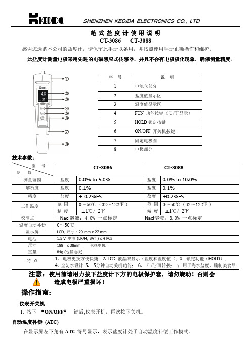
笔式盐度计使用说明 CT-3086 CT-3088
感谢您选购本公司的盐度计,请保留此手册以备用,并按照使用手册正确操作和维护。
此盐度计测量电极采用先进的电磁感应式传感器,并且不会有电极极化现象,确保测量精度。
序号
说明
1
电池仓部分
1.5 V 电池 (LR44, BAT ) x 4 PCs
尺寸
188 x 38mm 包括电极.
重量
84g (包括电极).
特点
1. 电极更换方便快捷;2. LCD 液晶双显示(盐度和温度值 );3. 锁定功能(HOLD); 4. 全防水设计 5. 5分钟自动关机功能; 6. ℃/℉可转换; 7. 用于海水盐度、腌制类食品
特别说明:1. CT-3086 电极部分放入 4% 的 NaCL 溶液中,盐度显示值应在 3%-5%范围内,
2. CT-3088 电极部分放入 8% 的 NaCL 溶液中,盐度显示值应在 7%-9%范围内,
如果两型号超出上述范围,盐度计不能标定。用恢复出厂设置功能,清除错误数据。
恢复出厂设置: 按“HOLD”键不放,等待显示屏出现 CLr 符号,放开按键即可。 重新标定后使用
2
盐度值显示区
电导-TDS-盐度说明书
产品说明书User’s Guide□CT-3030 □CT-3050 □CT-3060 □CT-3070 □CT-3080 □CT-3090目录面板介绍/产品特点/技术参数 (3)1、CT-3030 (5)2、CT-3050 (7)3、CT-3060 (9)4、CT-3070 (11)5、CT-3080 (13)6、CT-3090 (15)操作指南 (17)1、CT-3030/CT-3060/CT-3080操作指南-----------------------------------------------------------------------------------------------------172、CT-3050/CT-3070/CT-3090操作指南----------------------------------------------------------------------------------------------------24感谢您选购本公司的产品,请保留此手册以备用,并按照使用手册正确操作和维护。
使用前请先用干净水浸泡电极5-10分钟使电极活化。
外观介绍CT-3030电导率测试笔特点技术参数CT-3050 电导率测试笔特点技术参数CT-3060 TDS测试笔特点技术参数CT-3070 TDS测试笔特点技术参数CT-3080 盐度计特点技术参数CT-3090 盐度计特点技术参数CT-3030/CT-3060/CT-3080操作指南使用前请用力拔下仪表下方的电极保护套,请勿旋动!1.锁定功能CT-3030/CT-3060/CT-3080按ON/OFF开机,在正常工作时按下“HOLD”键将锁定液晶显示屏上的当前数据,并且在显示屏上会显示HOLD符号(如下图所示),再按下“HOLD”键即解除锁定模式,HOLD符号消失。
CT-3030 CT-3060 CT-30802.自动温度补偿(ATC)在液晶显示屏左下角有ATC符号出现,表示仪表正处于自动温度补偿工作模式。
盐度计操作手册
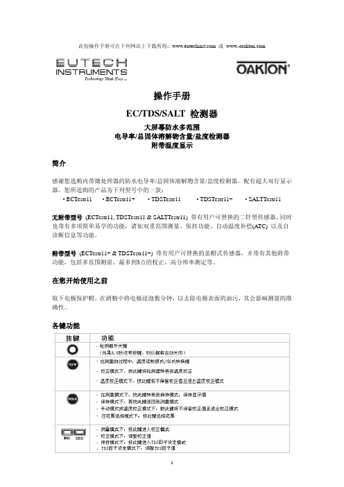
此份操作手册可在下列网站上下载所得: 或 操作手册EC/TDS/SALT 检测器大屏幕防水多范围电导率/总固体溶解物含量/盐度检测器附带温度显示简介感谢您选购内带微处理器的防水电导率/总固体溶解物含量/盐度检测器,配有超大双行显示器。
您所选购的产品为下列型号中的一款:• ECTestr11 • ECTestr11+ • TDSTestr11 • TDSTestr11+ • SALTTestr11无附带型号 (ECTestr11, TDSTestr11 & SALTTestr11) 带有用户可替换的二针型传感器,同时也带有多项简单易学的功能,诸如双重范围测量、保持功能、自动温度补偿(ATC) 以及自诊断信息等功能。
附带型号 (ECTestr11+ & TDSTestr11+) 带有用户可替换的盖帽式传感器,并带有其他附带功能,包括多范围测量、最多到3点的校正、高分辨率测定等。
在您开始使用之前取下电极保护帽,在酒精中将电极浸泡数分钟,以去除电极表面的油污,其会影响测量的准确性。
各键功能注释:INC和DEC键位于电池盒内。
参见图1注释:对于ECTestr11 & ECTestr11+型号的仪器,其HOLD键上面写的是“HOLD/ENT”开机按ON/OFF键打开检测器。
液晶显示器上将显示如图2所示的开机流程。
开机后如果您8.5秒没有按任何键,仪器将自动关闭来保存电池。
选择范围根据您选择的产品,您可以把检测器的读书限定在一个特别的测量分为 (PU, LO或HI),或者满量程 (AUTO)。
默认值为AUTO。
如果您设定的范围为非AUTO,则检测器在校正过程中只能使用所设定的特别范围。
如果您所测样品的电导率/TDS大于所设定的测量范围,则LCD上会显示“OR”的错误信息。
各型号的测量范围参见样品型号一章。
范围选择步骤:1.关闭检测器。
按住°C/°F键不放,然后用ON/OFF键打开检测器。
卤汤盐度计使用方法-概述说明以及解释

卤汤盐度计使用方法-概述说明以及解释1.引言1.1 概述卤汤盐度计是一种用于测量卤汤盐度的仪器。
在食品行业和化学实验中,卤汤盐度的准确测量对于保证食品味道和化学实验结果的稳定性至关重要。
本文将介绍卤汤盐度计的使用方法,以及在使用过程中需要注意的事项。
首先,我们将会详细讲解卤汤盐度计的原理,这对于正确使用卤汤盐度计至关重要。
了解原理将帮助我们更好地理解盐度计的工作机制,从而提高我们使用盐度计的准确性和效率。
接下来,我们将介绍卤汤盐度计的使用步骤。
从准备工作开始,包括确认设备的完好性和校准,到具体的操作步骤,例如如何将样品放入盐度计、如何读取盐度计的示数等等。
这些步骤的正确执行将确保我们测量的准确性,并且提供可靠的数据。
然而,使用卤汤盐度计时也需要注意一些事项。
我们将会列举一些常见的注意事项,例如避免污染样品、正确保管和清洁盐度计、防止误操作等等。
这些注意事项将帮助我们在使用卤汤盐度计时避免常见的错误和问题,从而保证测量结果的可靠性和准确性。
综上所述,本文将详细介绍了卤汤盐度计的使用方法、原理和注意事项。
通过正确理解并遵守这些内容,我们将能够更好地使用卤汤盐度计,提高测量的准确性,为食品行业和化学实验提供可靠的数据支持。
同时,我们也将对卤汤盐度计的优缺点进行评价,并展望其未来的发展。
1.2 文章结构文章结构部分的内容:本篇文章主要分为引言、正文和结论三个部分。
引言部分主要包括概述、文章结构和目的三个方面。
在概述中,将介绍卤汤盐度计的背景和作用,让读者对卤汤盐度计有一个整体的了解。
文章结构部分将详细介绍本篇文章的组织结构,包括各个章节的内容和安排,以使读者在阅读时能够清晰地了解到文章的框架。
目的部分将明确本篇文章的写作目的,即介绍卤汤盐度计的使用方法,使读者能够掌握该仪器的操作步骤和注意事项。
正文部分将分为三个小节,分别是卤汤盐度计的原理、使用步骤和注意事项。
在原理部分,将详细介绍卤汤盐度计的工作原理,包括采用的测量原理和工作原理,以帮助读者理解仪器的基本工作原理。
笔式高浓度盐度计安全操作及保养规程

笔式高浓度盐度计安全操作及保养规程笔式高浓度盐度计是一种用于测量水中盐度浓度的仪器,广泛应用于海洋、渔业、食品加工等行业。
为确保仪器的使用效果和安全性,特制定以下安全操作及保养规程。
安全操作规程1. 仪器防护笔式高浓度盐度计属于精密仪器,应保证防尘、防水、防震。
在使用前应先清洁检查仪器,如果发现裂缝或故障应及时更换或修理,保持仪器的完好无损。
2. 使用环境笔式高浓度盐度计适用于室内和室外环境,但不能在高温、高湿或极端寒冷环境下使用。
应避免接近磁场或强电场,以免影响仪器的测量精度。
3. 操作方法使用前应先阅读仪器操作说明书,按照说明书的操作方法进行使用。
在测量时应按照测量程序进行,不能随意更改或调整。
每次使用前应判断电池是否充足,如电池电量过低应及时更换电池。
4. 测量时间每次单次测量时间应控制在2分钟以内,如超时应停止测量,并等待几分钟后再重新测量。
在连续多次测量时,要注意休息和排除突发因素的干扰,以保证测量数据的准确性。
5. 仪器保养每次使用后应将笔式高浓度盐度计清洗干净,并用干燥的纸巾擦干。
在长期存放或不使用时,应先取出电池并妥善保管,避免高温或阳光暴晒。
仪器存放之前应先清理干净,并使用防尘套进行包装。
保养规程1. 清洗保养在使用时,使用人应注意保持温度恒定,如发现温度变化较大应重新校准,避免产生误差。
同时在使用完毕后应及时清理各个部位,避免不必要的故障和损坏。
2. 防水保养笔式高浓度盐度计具有防水功能,但还是需要保持干燥,防止腐蚀和生锈。
每次使用后应将仪器清洗、擦干、放置在防潮箱内,以免长时间浸泡在水中或高湿环境下。
3. 校准保养为保证笔式高浓度盐度计的测量精度,定期进行校准是非常必要的。
一般情况下,建议每季度进行一次校准。
同时在使用仪器时也要注意环境因素的影响,比如温度、湿度和磁场等,如发现有干扰影响测量精度应及时更换测量环境。
总结笔式高浓度盐度计是一种非常常用的仪器,为了保证仪器的使用效果和安全性,制定上述安全操作及保养规程。
三信笔式海水盐度计安全操作及保养规程

三信笔式海水盐度计安全操作及保养规程1. 引言三信笔式海水盐度计是一种用于测量海水盐度的仪器。
本文档旨在向用户介绍正确的操作方法以及保养规程,以确保海水盐度计的正常使用和延长其使用寿命。
2. 安全操作规程以下是安全操作海水盐度计的规程:2.1 基本操作•操作前,请先阅读并理解使用手册中的相关内容。
•使用前,确保海水盐度计处于良好的工作状态,检查是否有任何破损或损坏。
•打开盖子,将样品采集针和测量区域正确对准。
•使用样品采集针获取海水样品,并将其滴入测量区域。
•关闭盖子,并等待几秒钟,让海水充分被吸入。
•借助读数表盖打开测量区域,读取盐度值。
2.2 注意事项•在操作海水盐度计时,务必小心谨慎,避免碰撞或摔落。
•避免浸泡盐度计在水中超过规定时限。
•始终使用清洁的水和干净的毛巾清洁海水盐度计,并避免使用任何含有酸碱性物质的清洁剂。
•确保海水盐度计在使用结束后完全干燥,然后放置在干燥通风的地方,避免阳光直射。
3. 保养规程正确的保养可以有效延长海水盐度计的使用寿命和保持准确的测量结果。
3.1 日常保养•使用后,及时将海水盐度计清洗干净,避免样品残留在仪器中。
•定期检查海水盐度计的外观和配件是否完好,如有损坏或丢失,请及时更换。
•定期校准海水盐度计,以确保测量结果的准确性。
3.2 季度保养每个季度,进行一次深度清洁和维护:•拆卸海水盐度计,清洗所有零件。
•用软布或棉签擦拭海水盐度计的内部和外部表面。
•仔细检查电池情况,并更换旧电池。
•使用海水盐度计的专用校准液校准测量结果。
4. 故障排除以下是可能遇到的一些常见问题及解决方法:•问题:盐度计读数不准确。
解决方法:检查是否需要更换电池,如果电池正常,则使用校准液重新校准。
•问题:海水盐度计无法打开或关闭。
解决方法:检查盐度计盖子是否正确安装,如有损坏请更换盖子。
•问题:读数盖无法打开。
解决方法:检查是否正确安装,小心弹开读数盖,避免造成损坏。
如果以上问题无法解决,请联系三信笔式海水盐度计的售后服务支持。
LAQUAtwin-Salt-22 盐度测量仪说明书

Instruction Manual (Operation)COMPACT WATER QUALITY METERLAQUAtwin-Salt-22SpecificationsItems in packageConsumable parts sold separately Part NamesNotePress the switches 0.5 seconds or more unlessotherwise specified.Initial SetupAttaching/detaching the sensorNoteBe careful not to twist the waterproof gasket.Inserting/removing batteriesElectrode conditioningNote●Before using the sensor for the first time orafter several days of disuse, perform electrodeconditioning.●Perform calibration after electrode condition-ing.1.Place some drops of 5.0% standard solu-tion to the flat sensor.2.Wait a few hours before use.There is no need to switch the meter ON.3.Clean the flat sensor with running water.Model LAQUAtwin-Salt-22Target SalinityMeasurement principle ISE method Minimum sample volume More than 0.3 mL*1 Measure-ment range0.01% to 25% by weightResolution (default)Display range:Resolution0.00% to 0.99%:0.01%1.0% to 9.9%:0.1% 10% to 25%:1%Calibration Up to 2 pointsDefault: 0.5% and 5.0%Accuracy*2±10% of reading valueWaterproof IP67 (no failure when immersed inwater at a depth of 1 m for 30 min) *3 Display Custom (monochrome) digital LCDwith backlightOperating environment Temperature: 5︒C to 40︒C Humidity: 85% relative humidity or less (no condensation)Power CR2032 batteries (⨯2)Battery life Approx. 400 h continuous operation(backlight off mode)*4Material ABS epoxy (main material) Dimensions164 ⨯ 29 ⨯ 20 mm (excluding projec-tions)Mass Approx. 50 g (excluding batteries)*10.05 mL or more if sampling sheet B (sold sepa-rately) is used.*2The closeness of agreement between a mea-sured value and an actual value of standard solu-tion after two-point calibration using 0.5% and5.0% standard solutions.●The standard solution used for the later cali-bration was measured after two-point calibra-tion at 0.5% and 5.0%.●The calibration and measurement are per-formed at the same temperature.●The error of standard solutions and roundingerror (±1 digit) are not included.*3The meter cannot be used underwater.*4When the backlight is used, battery life willshorten.Items QuantitySensor S0211Meter1Storage case1Batteries CR20322Standard solution0.5%15.0%1Pipette1Sampling sheet B (5 sheet-pack)1Instruction manual (Operation)1Instruction manual (Before use)1Items Specifications Part No.Sensor S021, Salt3200459866Standardsolution514-05, NaCl 0.5%3999960112514-50, NaCl 5.0%3999960113Samplingsheet BY046, 100 sheet-pack32000538581Flat sensor2Light shield cover3Liquid junction4Response mem-brane5Lithium batteries6MEAS switch7ON/OFF switch8CAL switch9Waterproof gasket10Strap eyeletAttaching the sensor1.Power OFF the meter.2.Confirm that the waterproofing gasket isclean and undamaged.3.shown.Detaching the sensor1.Power OFF the meter.2.Lift the sensor tonguetip and slide the sensora little away from themeter.3.Pull out the sensor all the way from themeter.Inserting the batteries1.Power OFF the meter.2.Slide both batteries intothe battery case asshown.Be sure to use twoCR2032 batteries, and putthem with the plus sides(+) upwards.Removing the batteries1.Power OFF the meter.e a ball-point pen orother tool to pry the batter-ies out from the clips asshown.CODE: GZ0000460290Basic OperationCalibrationCalibration is required before measurement.Use standard solution within the measurement range in the specifications.Tip●Calibration values are saved even if the meteris switched OFF.●Calibration value is rewritten if calibration isrepeated using the same standard solution.TipFor accurate measurement, calibrate using 2 points of standard solution with a tenfold or more salinity difference encompassing the target salin-ity.When the salinity to be measured is very high or very low, accuracy may be poorer. MeasurementPower ON1.Press and hold the ON/OFF switch.The power is switched ON,and the meter modelnumber is displayed on theLCD.Power OFF1.Press and hold the ON/OFF switch.The power is switched OFF.Calibration pointsThe number of calibration points is up to 2.Multi-point calibration1.Set the salinity of standard solution for cal-ibration referring to " 1st calibrationpoint setting" (page 5) and " 2nd calibra-tion point setting" (page 5).The 1st point is set to 0.5% and the 2nd pointis set to 5.0% by the default.2.Open the light shield cover and place somedrops of the standard solution on the flatsensor taking care to cover the entire flatsensor.Rinsing the sensor with the standard solutionbeforehand will provide a more accuratecalibration as it will reduce sample crossovercontamination.3.Close the light shield cover and press theCAL switch.The meter enters the CAL mode and blinks thedisplay of the set 1st-point salinity. Pressingthe MEAS switch switches the displayed valuebetween the set salinity.4.With the set salinity of the 1st point dis-displayed.After the calibration is complete,displayed.The calibration value at 25 C is displayed for 1s and the display returns to the measurementmode automatically.5.Open the light shield cover and remove thestandard solution. Then remove moistureon the sensor by gently dabbing with a softtissue.This completes the 1st point calibration.6.To perform 2nd point calibration, repeatsteps 2. to 5.Calibration errorIf blinks and Er4 (error dis-play) appears, the calibrationhas failed.Perform electrode conditioning.Check that the correct standard solution is used,and repeat calibration after cleaning the sensor.If the calibration repeatedly fails when using thecorrect standard solution(s), the sensor mayhave deteriorated. Replace the sensor with newone.Sample setting1.Open the light shield cover and put somedrops of sample on the flat sensor to coverthe entire flat sensor.2.Close the light shield cover.Measurement modeThe auto stable (AS) mode and the auto hold(AH) mode can be selected. Refer to " Mea-surement mode change" (page 5) for the opera-tion to set the measurement mode.Auto stable (AS) mode1.Confirm that the meter is in the measure-ment mode, and place a sample on the sen-sor.locked.2.appears.Auto hold (AH) modeand will not change until the MEAS switch ispressed for the next measurement.1.Confirm that the meter is in the measure-ment mode, and place a sample on the sen-sor.2.Press the MEAS switch.The auto hold function isactivated.blinks until themeasured value hasstabilized.When the measured value is stable, stopsblinking and the displayed value is locked with3.Document the displayed value.4.Press the MEAS switch.disappears.Be sure to perform this step before starting thenext measurement. Or, you may mistake thedisplayed hold value for the next measuredvalue.●If a measured value is out of the specifiedmeasurement range, "Or" is displayed for upper range and "Ur" is displayed for under range.●When you have a problem with the calibrationor measurement, refer to frequently asked questions.Sampling sheetFor a minute sample●Note that reaction between sample and sam-pling sheet B may affect the measured value.●Handle sampling sheet B with tweezers tominimize possible contamination.●Be sure to close the light shield cover duringmeasurement to minimize possible sample evaporation.For a sample containing tiny particles If tiny particles are contained in a sample, such as an extract from soil, the particles influence measurement results. Use the sampling sheet holder cover and sampling sheet B sold sepa-rately to counteract the influence.The sampling sheet holder cover does not shield the sensor from light, which affects the sensor. When using the sampling sheet holder cover, shield the flat sensor from light with an alterna-tive.1.Replace the light shield cover with the sam-pling sheet holder cover.2.Put a piece of sampling sheet B on the flatsensor and close the sampling sheet holder cover.3.Put 4 or 5 drops of sample on the samplingsheet B.The display mode switches among salinity, tem-perature, and voltage by pressing the MEASswitch in the AS mode.MaintenanceAppendixInterfering ionsSelectivity coefficient is a concentration ratio ofthe interfering ion against the target ion, whichaffects the target ion measurement value. Forexample, selectivity coefficient of interfering ionagainst target ion is 1 ⨯ 10-2, which means for thesame concentration of interfering ion and targetion coexisting in a sample, the target measure-ment shows approximately 1 ⨯ 10-2 (1%) higherresult.minute sample.covered with only 50to 100 μL sample.Storage1.Clean the sensor with tap water.2.Dab gently with soft tissue or cloth toremove moisture on the sensor and meter.NoteEspecially be sure to treat the flat sensor gentlyto prevent damaging it.3.Close the light shield cover and the slidecap before storing the meter.Temperature sensor adjustmentTo perform accurate measurement with correc-tion for temperature effects, follow the stepsbelow. Normally this is not necessary.1.Ready a reference thermometer, and allowthe meter and reference thermometer toreach to room temperature.2.Set the display mode to temperature refer-ring to " Measurement display change"(page 3).3.Press the CAL switch.The meter displays the setting screen fortarget temperature.4.Press the MEAS switch to adjust the dis-played temperature on the meter to matchthe temperature indicated by the referencethermometer.Pressing the MEAS switch increases thedisplayed temperature. After the displayedtemperature reaches 40°C, it returns to 5°C.5.Press the CAL switch again to apply thedisplayed value to the adjustment.The adjustment starts. The adjusted valueblinks with and displayed.After the adjustment is complete, the adjustedvalue stops blinking with MEAS anddisplayed.If Er4 (error display) appears, the adjustmenthas failed. Retry the above steps increasingthe time spent on the step 1.If the adjustment repeatedly fails, the sensormay have deteriorated. Replace the sensorwith new one.Initializing calibration dataInitialize calibration in the following cases.●To delete the calibration data●If the number of points for the last calibration isuncertain.●After the sensor is replaced.1.Press and hold the CAL and ON/OFFswitches for over 3 seconds when themeter is switched OFF to Initialize calibra-tion.After a moment of all segment indication, thesoftware version is displayed.And then, the displaychanges as shown right.2.Press the CAL switch.All calibration data is reset.When the initialization ofcalibration data is complete,End appears.The meter automatically switches OFF.Initializing the settingsAll setup choices are erased. The meter is resetto the factory default values.1.Press and hold the MEAS, CAL and ON/OFFswitches for over 3 seconds when themeter is switched OFF to enter the initial-ization.After a moment of all segment indication, thesoftware version is displayed.And then, the displaychanges as shown right.2.Press the CAL switch.All calibration data is reset.When the initialization ofsettings is complete, Endappears.The meter automatically switches OFF.Target SalinityInterfering ions andselectivity coefficientsK+, Rb+: 1 ⨯ 10-2(at 10-3 mol/L Na+)pH range 3 pH to 9 pH(at 10-3 mol/L Na+)Frequently asked questionsEr4 is dis-played during the calibra-tion Please note that if you press the CAL switch in mV or temperature display mode, Er4 is displayed. This is because there is no calibration facility available for these modes.Er1 is dis-played soon power ON.The internal IC in the meter may be defective. Perform meter initializa-tion.If Er1 is still displayed after the initial-ization, the internal IC in the meter is defective. Replace the meter with a new one (the meter cannot be repaired).Er2 is dis-played right after power ON.The internal IC in the meter is defec-tive. Replace the meter with a new one (the meter cannot be repaired).Er3 is dis-played right after power ON.The internal IC in the meter is defec-tive. Replace the meter with a new one (the meter cannot be repaired).What factors interfere measure-ment?Acids influence measurement results. Measure within the range from 3 pH to 9 pH. Also, high-level monovalent cations, such as K+, may cause measurement errors. Refer to " Interfering ions" (page 3) for details.Are there any helpful tips or precautions to be aware for measure-ment?When the sample amount is enough, washing the sensor twice or so with the sample allows more accurate measurement.Residue between the light shield cover and flat sensor prevents accu-rate measurement. Before measure-ment of the next sample, wash the sensor with tap water and remove moisture.Question AnswerSetup ModeThe setup mode allows the user to customize the meter to his specific needs.To enter the setup mode, press and hold the MEAS and ON/OFF switches for over 3 seconds when the meter is switched OFF. All the LCD segments appear and then the meter enters the setup mode.Tip●To have the changes apply, you need to go through the entire steps from “Setup mode entry” to “Setup completion” shown below. To leave a setting as it is, just press CAL switch in the setting.●To exit the setup mode with no change of settings, press the ON/OFF switch earlier than pressing CAL switch in the last step but one, or the “Backlight setting” step.Setup mode entry1st calibration point settingThe salinity of the 1st calibration point can be set.NoteIf you changed either of the calibration salinity settings, calibrate again at the both set salinity before measurement.When either calibration salinity is changed, the calibration data are initial-ized.2nd calibration point settingThe salinity of the 2nd calibration point can be set.*In calibration point setting, pressing the MEAS switch increases the displayed value. After the displayed value reaches 24, it returns to 0.10.Measurement mode changeThe measurement mode can be switched.* Measurement display change is available in the AS mode. Refer to " Measurement display change" (page 3).Backlight settingThe backlight can be switched to ON or OFF.Setup completion31, Miyanonishi-cho, Kisshoin Minami-ku, Kyoto,。
BY2010智能盐密度测试仪新型使用说明书
BY2010智能盐密度测试仪(新型)使用说明书引言欢迎使用直读式等值盐密度测试仪(盐密仪)我们在设计建造输送容量大的电站和线路前应首先测定外绝缘的饱和盐密度以确定所在区域的污秽等级,选择合适的外绝缘爬电比距,使污闪事故率降低到本电力系统安全经济送电可以接受的程度(即可接受的污闪事故率),让国民经济损失降低到最少。
我国电力系统一般网架比较薄弱,多次污闪跳闸即有可能带来整个系统瓦解,引起大面积停电,某些污闪事故停电及检修时停电带来少送电量引起的损失,远远超过基建时外绝缘的投资。
污闪事故不同于一般单纯的设备事故,它涉及面广、影响设备多且分散,往往造成大面积、多设备的连锁事故。
对于已经投入使用高压输电线路、发电厂、变电站等场所的外绝缘设备应当每年至少检测一次其表面污秽程度,以衡量是否可能引起污闪事故。
作为判断外绝缘设备是否需要清洗或更换的依据。
我公司根据电力行业防治污闪的要求,针对进口电导仪器不能直接读出盐密度值的弊端,以及其对绝缘子盐密测试的不适应性,开发了最适合用户需求的BY2010绝缘子直读式等值盐密度测试仪,操作简单、功能齐全,得到了行业客户的一致认可。
目录一、依据标准 (3)二、术语解释 (3)三、仪器介绍 (3)四、性能指标 (4)五、产品特点 (4)六、操作方法详解 (5)6.1主菜单 (5)6.2查看记录 (7)6.3删除记录 (8)6.4参量设置 (8)七、现场测试方法及步骤 (9)八、保养维护 (10)九、随机附件 (11)十:附录 (13)一、依据标准GB /T 4585-2004 / IEC 60507 :1 991《交流系统用高压绝缘子的人工污秽试验》GB/T 16434—1996《高压架空线路和发电厂、变电所环境污区分级及外绝缘选择标准》GB 311.1—83 《高压输变电设备的绝缘配合》GB/T 5582—93 《高压电力设备外绝缘污秽等级》二、术语解释m表示。
等值盐密度:指污秽液等效为相同电导氯化钠溶液的溶质密度,通常以Kg/3绝缘子的爬电比距: 绝缘子的总爬电距离L除以试验电压与3的积;它通常以mm/kV来表示。
土壤盐分测量仪使用说明及操作方法

土壤盐分测量仪使用说明及操作方法土壤盐分测量仪使用说明及操作方法我们都知道这样一个道理,那就是植物只有在合适的条件下,才会生长良好。
这里说的条件可能是环境条件、土壤条件等,因此只要不满足了,那么很有可能就会对植物的生长造成损害,以土壤盐分为例,土壤中过多的盐分会阻碍植物正常生长发育,进而致使其品质变劣、产量降低。
因此在农业生产中,使用土壤盐分测量仪测量土壤盐分已经成为高品质栽培中的一项重要内容。
农业领域为什么要使用土壤盐分测量仪测量土壤盐分?主要还是因为土壤盐分超标会给植物生长造成影响,造成土壤盐分胁迫,因此在解答这个问题之前,不妨让我们看看土壤盐分胁迫对植物的伤害都有哪些?1.影响作物的光合作用:在土壤盐分胁迫下,植物会因为吸收不到足够的水分和矿质营养,从而造成营养不良,致使叶绿素含量低,影响光合作用。
2.影响作物的呼吸作用一般来说,盐分过多时总的趋势是呼吸消耗量多,净光合生产率低,不利于植物生长。
3.对植物细胞膜结构的影响土壤盐分胁迫会直接影响细胞的膜脂和膜蛋白,使脂膜透性增大和膜脂过氧化,从而影响膜的正常生理功能。
4.阻碍农作物蛋白质合成土壤盐分过多对蛋白质代谢影响比较明显,会抑制合成促进分解,从而使蛋白质含量减少。
另外还会使作物产生有毒物质,致使植物叶片生长不良,抑制根系生长,组织变黑坏死等。
由此可见,土壤盐分胁迫对于植物的伤害是不容忽视的,而由于过去不过范的化肥和农药的滥用,导致我国的耕地或多或少都存在土壤盐分超标的现象,因此要开展绿色无公害种植,高产农田种植,那么首先要做的就是使用土壤盐分测量仪来测量土壤盐分,进而指导科学改良措施的制定和开展,培育出优良的土壤环境,这样才能够真正实现农业的高质高产目标。
托普云农土壤盐分测量仪主要用于农业生产过程中各种土壤,水培养基质的盐分含量测量。
该土壤盐分测量仪可直接插入土壤速测并自动记录,大屏幕中文液晶显示数据,可将数据导入计算机。
一、托普云农土壤盐分测量仪技术参数土壤温度技术参数:温度单位:℃测试范围:-40℃~100℃精度:±0.5℃传感器长度:≥25cm分辨率:0.1℃土壤盐分技术参数:固态传感器可直接埋入土壤中测量范围:0~19.99ms/cm测量精度:±2%分辨率:0.01ms/cm温度补偿:0~50℃土壤水份技术参数:水份单位:%(m3/m3)响应时间:≤2秒土壤水份分辨率:0.1%标准电缆长度:1.5m(可按客户需要定做,最长可至1000m)可选件:测量地下深层土壤水分时建议使用土钻含水率测试范围:0~100%相对百分误差:≤3%二、托普云农土壤盐分测量仪手持机技术参数记录容量:设备内部Flash可存储近3万条数据,标配4G内存卡可无限存储,亦可与Flash中数据同时存储。
测水笔使用说明书

测水笔使用步骤
1、将笔杆下方陶土头浸入水中 1 小时。 2、拔出橡皮塞(带玻璃毛细管)。往玻璃毛细管内注
水,使毛细管顶端至 0 刻度处为空气,0 刻度以下充 满水。方法是:
(1)拔下毛细管上塑料小盖帽 。 (2)将注水用滴头上的塑料丝末端插入毛细 管的 0—10Kpa 刻度中间处。 (3)用手指挤出橡皮滴头内部分空气。 (4)将毛细玻璃管开口端没入冷开水中。 (5)缓缓松开捏住橡皮滴头的手指,水即进入 到 0 刻度处(能否使水正好进到 0 刻度处,关键 在于塑料丝放置的位置。 (6)拉出塑料丝(此时毛细管开口处仍没在水 中),水就会充满 0 刻度以下毛细管腔。若水中杂 有气泡,则需重新调节)。 (7)往盖帽内充满水。将.玻.璃.管.插.入.盖.帽.二.分. 之.一.处.。.玻.管.勿.堵.塞.盖.帽.边.上.小.圆.孔.。此时,毛细 管及盖帽中充水部分不应有气泡。 (8)将加水后的毛细玻璃管泡在水中备用。 3、往塑料笔杆内注入冷开水。 4、将已准备好的玻璃毛细管插入笔杆,将橡皮塞塞.紧.。 5、将测水笔插入土中根系主要活动层。若土质紧实, 用棍子打一孔,将测水笔插入土中,填实周边土壤。 使陶土头与周边土壤接触好。 6、土壤湿度状况观察: 笔杆插入土中一段时间后(湿润土壤约半小时,干燥 土壤需 2 小时以上),即可观察。看毛细管内空气柱 下缘所示的刻度数(Kpa 数)即可判断土壤的干燥度: 0—10Kpa 范围为潮湿;对多数植物而言,湿度过高。 10—30Kpa 范围为湿润;适宜多数植物生长的水分条件。
表 2:植物需灌时土壤水吸力范围(供参考)
10—20Kpa
20—30Kpa
30—50Kpa
花卉
湿生花卉类:热带 紫薇;玉兰;八仙 牡丹;桂花;月季;
兰类;凤梨科花 花;杜鹃;金莲花; 蔷薇;樱花;西府海
- 1、下载文档前请自行甄别文档内容的完整性,平台不提供额外的编辑、内容补充、找答案等附加服务。
- 2、"仅部分预览"的文档,不可在线预览部分如存在完整性等问题,可反馈申请退款(可完整预览的文档不适用该条件!)。
- 3、如文档侵犯您的权益,请联系客服反馈,我们会尽快为您处理(人工客服工作时间:9:00-18:30)。
盐分测试笔使用说明书
1、更换电池
(1)打开装电池的盒子(位于尾部有一个小环的地方)。
(2)换下废旧电池,装上新电池(注意电池的正负极)。
(3)换上新电池后请重新校准。
2、盐分测试笔的保存(保管)
为了提高盐分测试仪的性能,请定期清理电极。
清理时,请把电极放在酒精里浸泡10~15分钟。
如果读数显示微弱(或者读数不稳定),应换下所有电池。
当你需要更换一组新的电池时,请仔细阅读盒子内部的电池更换说明。
3、保修
该仪器的保质期是两年,电极组件的质保期是六个月。
如果不是故意损坏或因不良使用而造成仪器不能正常使用的,可免费维修、调整或替换。
在保修以外的产品需要维修的,需收取一定费用。
4、回收
在以任何原因回收(即更换)之前,必须从特定的分销商处得到授权。
申请回收(即更换)时,请说明回收(更换)的原因。
注意:我们保留产品的设计,结构和外形方面改进不需通知(用户)的权利。
仪器销售价格会根据变化而改变,也不另行通知。
5、电极更换
必要时,也可替换电极,其价格应向经销商咨询。
当测试仪无法准确校准或者在校准情况下出现波动指数,则需更换电极。
5.1用干燥的手,使电极方向对着我方,紧握住棱形状的测试笔帽逆时针方向拧紧笔帽(见图A)。
保留测试笔颈部“O”型圆环以备之后使用。
5.2取出旧电极,换上新电极(电池)。
5.3把新的组建上的四个凸舌排整齐以使它们符合测试仪上的四个孔(见图B)。
5.4轻轻的把电极推入槽中,使电极完全能卡在这个组件当中。
推入笔帽,然后顺
时针拧紧。
6、推动按钮校准
校准后,可得到迅速、稳定、可重复的读数。
7、运用范围
水质测试:水和盐分处理、水力发电试验、蒸发器(热水器,锅炉)。
工厂:生态研究以及更多的运用范围。
规格
(安全部翻译 2009年)。
