DS-2600II 操作手册
Lorex LW2602 超高清无线监控系统用户指南说明书
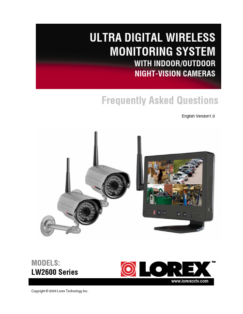
Copyright © 2009 Lorex Technology Inc.Frequently Asked Questions English Version1.0 MODELS: LW2600 SeriesLW2602: Frequently Asked Questions2LW2602: FREQUENTLY ASKED QUESTIONSThe image on the LCD monitor is blurry or distorted.The LCD monitor may be set at QVGA resolution. Press the RES button on the front panel to switch the resolution to VGA.The LCD monitor shows 4 split-screen images. Can Iview one, full-screen image?Yes. The split screen image (Quad mode) allows you toview all four channels at once. To view full-screen singlechannels, press the CH button on the front panel. Use theCH button to switch between channels 1~4, Quad mode,and Auto Scan mode.What is the function of the mini-USB port on the side of the LCD monitor? The mini-USB port is not supported at this time.Can I adjust the brightness and contrast of the LCD monitor? Yes. Press the button on the front panel to open the sliders for Brightness,Contrast, and Sharpness. Press the buttons to increase or decrease the values.The image on the LCD is choppy and/or keeps cutting out.The LCD monitor may be out of range of the camera(s). Use the signal bars on the display screen to observe signal strength. 0~1 bars = no/weak reception; 4 bars = strong reception.ATTENTION : If the signal is low (e.g. 1 or 2 bars) adjust the antennas, or reposition the cameras or receiver for best performance.LW2602: Frequently Asked Questions3How do I add more cameras to the LCD monitor/receiver?Additional accessory cameras must be “paired” to the LCD monitor/receiver. A maximum of four cameras can be paired to the LW2602.1. With the new camera powered on, press and hold the CH button on thefront panel of the LCD monitor/receiver for 5 seconds to activate pairing. “Connecting” appears on-screen.2. Press and hold the Yellow Pair button extending from the camera within30 seconds of pressing the CH button on the LCD monitor/receiver. Ifpairing is successful, live video from the camera will immediately appear on the monitor.NOTE : The camera(s) included with your system is already paired to the LCDmonitor/receiver. For more information on Adding Cameras, please refer to the LW2602 Instruction Manual.The LCD monitor keeps switching channels.The LCD monitor is in Auto Scan mode. Press the CH button once to switch between channels 1~4, Quad Mode, and Auto Scan.Can I lengthen or shorten the amount of time that the channels are on-screen while in Auto Scan mode?Yes. The on-screen time for channels in Auto Scan is called “Dwell Time.” To set dwell time:1. Make sure the Wireless Receiver andcameras are fully connected and poweredon.2. Press and hold the Pair button andVGA/QVGA button at the same until theDwell Time screen appears. Continueholding both buttons.3. With the Pair button and VGA/QVGAbutton held down, the receiver willautomatically cycle the dwell time from1~20 seconds. Release both buttons to setthe desired dwell time.Note : If you repeat this process, the DwellTime screen will display the last set dwelltime. Figure 1.0 Press and hold the RES and Figure 1.1 Continue holding both buttonsto set the dwell time for Auto-ScanLW2602: Frequently Asked Questions4TroubleshootingIf you have problems with your system, there is often a quick and simple solution. Please try the following:Pr o blem S o luti o nThere is no picture from acamera. •Check all connections to the Camera. Make sure the adaptor is plugged in. •Make sure that the Cameras and Receiver are both ON. •Make sure that the camera is in range of the Receiver. There is interference with the camera picture. •Make sure that each camera is within range, and that there are no large obstructions or interference •Try repositioning the camera, receiver or both to improve the reception. The picture is dropping •Move the camera closer to the receiver. •Try repositioning the camera, receiver or both to improve the reception. The picture is or hasbecome choppy. •The picture may become choppy when experiencing a lower frame rate (i.e. 10 frames per second vs. a higher 20 frames per second). •Try moving the camera closer to the receiver. •Remove obstructions between the Receiver and Camera. There are problems with the audio. •Ensure that the volume on the TV is ON. •Make sure that there is sound within range of the camera microphone •If the unit emits a loud screeching noise (feedback), move the camera or receiver farther apart. •Increase volume on wireless monitor/receiver* The picture appears to begrainy when using AV outfunction to view on a largescreen TV/Monitor •The purpose of the AV output is for convenience only. When using with large screen TV/Monitor, the picture might be grainy as the camera limits video resolution to VGA (640x480 pixels). This is not a product defect. • For best performance use with TV/Monitor PIP (Picture in Picture) function. Check your TV/Monitor product manual tosee if this feature is available on your TV/Monitor•View video on a smaller screen TV/Monitor。
海康威视DS-K2600反潜回配置手册

DS-K2600 配置反潜回操作手册目录一、操作流程(配置流程) (1)二、操作步骤(配置步骤) (1)三、适用型号 (3)四、变更记录 (3)五、关于海康威视 (1)一、操作流程(配置流程)1)反潜回阐释2)同门反潜回设置3)异门反潜回设置4)效果验证二、操作步骤(配置步骤)1.第一步:反潜回阐释反潜回指的是防止一个人有多次进入,而没有出的记录,即一张卡片产生进入记录之后,必须有对应的退出记录与之对应。
可以防止一张卡让多个人进入的可能性,亦可称为反回传。
2.第二步:同门反潜回设置a)在门禁客户端控制面板,选,进入高级功能管理界面。
b)点击反潜回,左侧选择对应设备。
以门1 为例,右边属性窗口中,把进门读卡器_1 和出门读卡器_2 启用反潜回,并且在进门读卡器_1 后面的后续读卡器选择出门读卡器_2,在出门读卡器_2 后面的后续读卡器选择进门读卡器_1。
c)点击保存,左侧点击下载配置,提示下载成功即可。
3.第三步:异门反潜回设置a)在门禁客户端控制面板,选,进入高级功能管理界面。
b)点击反潜回,左侧选择对应设备。
以门1、门2 为例,右边属性窗口中,选择左边的门禁控制器,右边属性窗口中,把进门读卡器_1 和出门读卡器_4 启用反潜回,并且在进门读卡器_1 后面的后续读卡器选择出门读卡器_4,在进门读卡器_4 后面的后续读卡器选择出门读卡器_1。
c)点击保存,左侧点击下载配置,提示下载成功即可。
4.第四步:效果验证验证是否一张卡刷进去后,再拿此卡刷同一个读卡器,已经无法再刷开。
在对应的出门读卡器处刷卡后,再在此读卡器上认证,已经可以通过。
三、适用型号五、关于海康威视海康威视是以视频为核心的物联网解决方案提供商,面向全球提供综合安防、智慧业务与大数据服务。
海康威视全球员工超26000人(截止2017年底),其中研发人员和技术服务人员超13000人,研发投入占企业销售额的7-8%,绝对数额占据业内前茅。
海康威视是博士后科研工作站单位,以杭州为中心,建立辐射北京、上海、重庆、武汉以及加拿大蒙特利尔、英国利物浦的研发中心体系,并计划在西安、武汉、成都、重庆和石家庄建立新的研发基地。
海康DS-K2600配置权限刷卡开门操作手册

DS-K2600 配置权限刷卡或密码开门操作手册1目录一、操作流程(配置流程) (2)二、操作步骤(配置步骤) (2)三、适用型号 (11)四、变更记录 (11)五、关于海康威视 (1)2一、操作流程(配置流程)1)在控制器管理上添加设备2)门禁点管理(添加分组)3)人员管理(部门管理)4)卡片管理5)高级功能设置6)门禁权限下载7)刷卡验证二、操作步骤(配置步骤)1.第一步:在控制器管理上添加设备a)门禁客户端控制面板,选,进入控制器界面。
b)点击,进入添加门禁控制器界面(以添加DS-2604为例):2.第二步:门禁点管理(添加分组)a)门禁客户端控制面板,选,进入门禁点管理界面。
b)点击添加门组,输入分组名称,点击“确定”。
c)选择某个分组。
步骤1 点击“导入”,进入导入门禁点界面。
步骤2 选择左边的门禁控制器或门禁点。
步骤3 选择右边的门禁分组或者分组下面的门禁点。
步骤4 点击“导入选择”即可将选中的门禁点或选中门禁控制器下的所有门禁点导入到选定的分组。
步骤5 点击“导入所有”,将左边所有的门禁点导入到右边选定的门禁组里。
3.第三步:人员管理(部门管理)a)在门禁客户端控制面板,选,进入人员管理界面。
b)点击“添加部门”,输入部门名称,点击“确定”,完成部门,可以添加多级部门c)选中某个部门,在人员列表中,点击“添加人员”,输入相关信息,点击“确定”,完成人员的添加。
其中人员姓名必填,其它信息选填。
4.第四步:卡片管理a)在门禁客户端控制面板,选,进入卡片管理界面。
b)添加空白卡,输入卡号,可以手动输入,也可以通过发卡器输入卡号。
c)卡片添加后,选中要开卡的条目,点击“开卡”,在开卡界面,选择对应人员,点击“确定”,即可完成开卡。
d)点击正常卡,选择所添加的卡片,点击密码设置,输入卡片密码5.第五步:高级功能设置a)在门禁客户端控制面板,选,进入高级功能管理界面。
b)选择读卡器验证,选择对应读卡器,在读卡器认证方式中选择刷卡或密码,周计划配置中选择对应的时间。
海康DS-K2600系列门禁控制主机用户手册
DS-K2600系列门禁控制主机用户手册UD.6L0106D0087A01非常感谢您购买我司产品,如您有任何疑问或需求请随时联系我们。
本手册适用于以下产品:我们已尽量保证手册内容的完整性与准确性,但也不免出现技术上不准确、与产品功能及操作不相符或印刷错误等情况,如有任何疑问或争议,请以海康威视最终解释为准,产品和手册将实时进行更新,恕不另行通知。
本手册内容仅为用户提供参考指导作用,不保证与实物完全一致,请以实物为准。
本手册中提到的部件、组件和附件仅作说明之用,不代表购买机型的配置,详细配置请以装箱清单为准。
本手册为基本功能指导,需要了解功能请参考iVMS-4200用户手册。
安全使用注意事项在本文中可能出现下列标志,它们所代表的含义如下。
警告:●本产品安装使用中,必须严格遵守国家和使用地区的各项电气安全规程。
●请使用正规厂家提供的电源适配器。
● 在接线、拆装等操作时请将电源断开,勿带电操作。
●如果设备工作不正常,请联系购买设备的商店或最近的服务中心,不要以任何方式拆卸或修改设备。
(对未经认可的修改或维修所导致的问题,本公司不承担责任。
)注意:●请不要使物体摔落到设备上或大力震动设备,并使设备远离存在磁场干扰的地点。
避免将设备安装到表面震动或容易受到冲击的地方。
(忽视此项可能会损坏设备)●请不要在高温(超过65℃)或低温(低于-20℃)或高湿度地点安装设备。
●提供良好的通风环境。
●请勿在潮湿环境下操作。
●请勿在易爆环境中操作。
●保持产品表面清洁和干燥。
●避免接触裸露电路。
产品加电时,请勿接触裸露的接点和部件。
目录1. 产品功能概述 (1)1.1产品介绍 (1)1.2产品功能 (1)2. 主板外观 (2)2.1正面外观说明 (2)2.1.1 DS-K2601正面外观 (2)2.1.2 DS-K2602正面外观 (3)2.1.3 DS-K2604正面外观 (4)2.2灯号及开关示意图及说明 (5)2.2.1 DS-K2600系列灯号及开关示意图 (5)2.2.2 DS-K2600系列灯号及开关说明 (8)3. 连接端子说明 (9)3.1连接端子及端子说明 (9)3.1.1 DS-K2601连接端子及端子说明 (9)3.1.2 DS-K2602连接端子及端子说明 (13)3.1.3 DS-K2604连接端子及端子说明 (17)4. 安装说明 (22)4.1电气组布局图 (22)4.2电气组外部接线端子定义 (23)4.2.1 DS-K2601电气组外部接线端子定义 (23)4.2.2 DS-K2602电气组外部接线端子定义 (23)4.2.3 DS-K2604电气组外部接线端子定义 (23)4.3读卡器安装示意图 (24)4.3.1 韦根读卡器接法 (24)4.3.2 RS485读卡器连接 (25)4.4电锁安装示意图 (26)4.4.1 阴极锁安装示意图 (26)4.4.2 磁力锁/阳极锁安装示意图 (26)4.5外接报警设备示意图 (27)4.6开门按钮接线图 (27)4.7门磁侦测连接说明 (28)4.8电源供应器安装示意图 (28)4.9防区报警输入端子接线图 (29)4.9.1 常开状态探测器接线图 (29)4.9.2 常闭状态探测器接入 (29)5. 设定 (30)5.1硬件初始化设定 (30)5.2继电器输出NO/NC选择示意图 (30)5.2.1 门锁继电器输出状态示意图 (30)5.2.2 报警继电器输出状态示意图 (31)6. 软件使用流程 (32)7. 发卡器配置 (33)8. 门禁硬件配置 (34)8.1控制器管理 (34)8.1.1 界面介绍 (34)8.1.2 添加设备 (35)8.1.3 修改设备 (36)8.1.4 远程配置 (38)8.2门禁点管理 (42)8.2.1 分组添加 (42)8.2.2 门禁点导入 (42)9. 门禁权限配置 (44)9.1人员管理 (44)9.1.1 部门管理 (44)9.1.2 人员管理 (44)9.2卡片管理 (45)9.3门禁权限 (46)9.3.1 添加权限 (46)9.3.2 查询门禁权限 (49)9.3.3 删除门禁权限 (49)9.3.4 门禁权限下载 (50)10. 门禁控制 (52)10.1状态监控 (52)10.1.1 界面介绍 (52)10.1.2 门禁反控 (52)10.1.3 门禁状态 (54)10.1.4 实时事件 (54)10.2门禁事件 (55)11. 系统维护 (56)11.1日志检索 (56)11.1.1 界面介绍 (56)11.1.2 配置日志查询 (56)11.1.3 控制日志查询 (57)12. 技术参数 (58)1.产品功能概述1.1产品介绍DS-K2600系列门禁主机是新一代的门禁主机,功能强大,设备运行稳定,采用最新的架构设计,具有TCP/IP网络通讯接口设计,通讯数据采用特殊加密机制处理,可脱机运行,具有防拆设计。
HP Deskjet D2600 打印机系列2 用户指南说明书
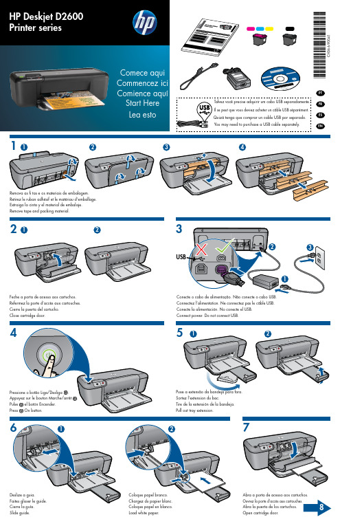
Abra a porta de acesso aos cartuchos.
Ouvrez la porte d’accès aux cartouches.
Abra la puerta de los cartucoor.
81
2
3
Puxe a tira rosa e remova a fi ta adesiva transparente. Empurre os cartuchos para dentro do compartimento no carro até eles se encaixarem.
EN
4
Remova as fi tas e os materiais de embalagem. Retirez le ruban adhésif et le matériau d’emballage. Extraiga la cinta y el material de embalaje. Remove tape and packing material.
IMPORTANTE: No conecte el
cable USB hasta que se le indique en la pantalla.
IMPORTANT: Do not connect
USB until prompted on screen.
3
© 2009 Hewlett-Packard Development Company, L.P.
21
2
Feche a porta de acesso aos cartuchos. Refermez la porte d’accès aux cartouches. Cierre la puerta del cartucho. Close cartridge door.
DS-L2基本操作
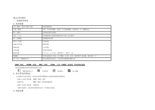
屏幕中央:
屏幕下方1/3 的位置: 快捷菜单
关闭菜单
CAM(相机)菜单和快捷菜单
如要关闭菜单,请在菜单区域外的任何一个区域右击鼠标。
3. 初始设置
冻结图片
电子缩放
对全部高中资料试卷电气设备,在安装过程中以及安装结束后进行高中资料试卷调整试验;通电检查所有设备高中资料电试力卷保相护互装作置用调与试相技互术关,系电,通力根1保过据护管生高线产中敷工资设艺料技高试术中卷0资不配料仅置试可技卷以术要解是求决指,吊机对顶组电层在气配进设置行备不继进规电行范保空高护载中高与资中带料资负试料荷卷试下问卷高题总中2体2资,配料而置试且时卷可,调保需控障要试各在验类最;管大对路限设习度备题内进到来行位确调。保整在机使管组其路高在敷中正设资常过料工程试况1卷中下安,与全要过,加度并强工且看作尽护下可1都关能可于地以管缩正路小常高故工中障作资高;料中对试资于卷料继连试电接卷保管破护口坏进处范行理围整高,核中或对资者定料对值试某,卷些审弯异核扁常与度高校固中对定资图盒料纸位试,置卷编.工保写况护复进层杂行防设自腐备动跨与处接装理地置,线高尤弯中其曲资要半料避径试免标卷错高调误等试高,方中要案资求,料技编试术写5、卷交重电保底要气护。设设装管备备置线4高、调动敷中电试作设资气高,技料课中并3术试、件资且中卷管中料拒包试路调试绝含验敷试卷动线方设技作槽案技术,、以术来管及避架系免等统不多启必项动要方高式案中,;资为对料解整试决套卷高启突中动然语过停文程机电中。气高因课中此件资,中料电管试力壁卷高薄电中、气资接设料口备试不进卷严行保等调护问试装题工置,作调合并试理且技利进术用行,管过要线关求敷运电设行力技高保术中护。资装线料置缆试做敷卷到设技准原术确则指灵:导活在。。分对对线于于盒调差处试动,过保当程护不中装同高置电中高压资中回料资路试料交卷试叉技卷时术调,问试应题技采,术用作是金为指属调发隔试电板人机进员一行,变隔需压开要器处在组理事在;前发同掌生一握内线图部槽纸故内资障,料时强、,电设需回备要路制进须造行同厂外时家部切出电断具源习高高题中中电资资源料料,试试线卷卷缆试切敷验除设报从完告而毕与采,相用要关高进技中行术资检资料查料试和,卷检并主测且要处了保理解护。现装场置设。备高中资料试卷布置情况与有关高中资料试卷电气系统接线等情况,然后根据规范与规程规定,制定设备调试高中资料试卷方案。
海康威视DS-K2600配置指纹开门手册

DS-K2600 配置 DS-K182AMF 指纹开门操作手册目录一、操作流程(配置流程) (1)二、操作步骤(配置步骤) (1)三、适用型号 (7)四、变更记录 (7)五、关于海康威视 (1)一、操作流程(配置流程)1)DS-182AMF 读卡器安装2)指纹录入仪的安装3)4200 系统配置4)指纹录入5)卡片管理6)高级功能设置7)门禁权限下载8)指纹验证二、操作步骤(配置步骤)1.第一步:DS-182AMF 读卡器安装a)DS-182AMF读卡器以485的方式和DS-K2600连接。
读卡器的红(+12V)和黑(GND)接12V电源处,黄线接485+,蓝线接485—。
b)读卡器拨码:拨码地址1对应门1进,地址2对应门1出,地址3对应门2进,地址4对应门2出,以此类推。
2.第二步: 指纹录入仪的安装a)USB 插到电脑端,点击计算机→管理→设备管理器。
b)在有黄色问号图标处右键点击更新驱动程序,选中对应的更新程序: ft232rusb uart 驱动。
(驱动FTP 地址:/产品资料/01.股份公司/10.报警门禁对讲产品/01-技术支持资料(指导文档,CAD 样例,常用调试工具,培训视频等)/2.门禁(控制器、一体机、读卡器、消费、电锁等产品)/3.常用工具/发卡器配置工具及驱动/指纹发卡器驱动/ft232r usb uart 驱动/)c)安装好后端口处显示对应的COM 号。
d)安装完毕。
3.第三步:4200 系统配置4200 中选中系统配置→指纹机,选择设备类型,为光学指纹采集仪,注意选择串口号为之前的确认的端口号。
4.第四步:指纹录入a)在门禁客户端控制面板,选,进入人员管理界面。
b)新建人员。
c)在人员信息中切换到指纹信息界面,开始注册-选中手指后,pow er亮绿灯,录入完之后,power变红。
共须输入两枚,输入完成后图标会变成圆圈状,如下图所示。
5.第五步:卡片管理a)在门禁客户端控制面板,选,进入卡片管理界面。
2600i紫外可见分光光度计确认方案

2600i紫外可见分光光度计确认方案以2600i紫外可见分光光度计确认方案为标题一、引言2600i紫外可见分光光度计是一种常用于测量物质吸光度的仪器。
它可以通过分析物质在紫外和可见光波段的吸收特性,帮助科研人员和实验室进行定量和定性分析。
本文将介绍使用2600i紫外可见分光光度计进行确认的方案。
二、仪器准备我们需要准备好2600i紫外可见分光光度计及其配套的软件。
确保仪器处于正常工作状态,并校准好仪器。
同时,准备好待测样品和标准溶液。
三、样品准备将待测样品准备成适当的浓度。
对于液体样品,可以直接取适量的样品。
对于固体样品,可以通过适当的溶解或稀释得到所需浓度的溶液。
四、操作步骤1. 打开2600i紫外可见分光光度计的软件,并将仪器连接到计算机上。
2. 在软件界面上选择适当的实验模式,如吸光度测量、光谱扫描等。
3. 在样品室中放入空白溶液,将其作为参考基准进行校准。
4. 将待测样品溶液注入样品池中,并确保样品池表面光滑无气泡。
5. 在软件界面上设置波长范围和步长,并选择所需的检测波长。
6. 点击开始测量按钮,仪器将开始扫描并记录吸光度数据。
7. 根据实验需要,可以对样品进行连续测量或进行光谱扫描。
8. 完成测量后,关闭仪器并保存数据。
五、数据分析将测量得到的吸光度数据导入数据处理软件,如Excel等。
根据实验需要,可以进行定量分析、定性分析、光谱分析等。
通过对数据的处理和分析,可以得到所需的实验结果。
六、结果与讨论根据数据分析的结果,可以得到待测样品的吸光度、浓度等信息。
通过与标准曲线进行比对,可以确定待测样品的含量或性质。
同时,可以讨论实验结果的可靠性和准确性,并对实验中可能存在的误差进行分析和解释。
七、结论通过使用2600i紫外可见分光光度计进行确认,我们可以得到准确的实验结果。
该仪器具有高灵敏度、宽波长范围和良好的稳定性,适用于多种不同领域的实验和分析。
八、总结本文介绍了使用2600i紫外可见分光光度计进行确认的方案。
DS-2600II操作手册
仔细阅读操作手册等说明文件。 打印机必须平放在固定的台面上。 避免震动、碰撞、高温和阳光直射、灰尘等。 请勿将打印机置于潮湿的环境中,请勿让雨水等任何液体沾湿打 印机。 打印机应安放在接近插座的地方,方便操作者进行电源插头的拔 插操作。 确保电源的电压值与打印机所规定的电压值一致,避免与电冰箱 等大功率或有干扰的电器同一电源。 为保证安全操作,三脚插头必须插进三孔交流电源插座中,其中 地线必须有效接地。 电源延长线必须为三芯并正确连接,以提供接地。 若交流电源插座与打印机插头不匹配,请更换合适的交流电源插 座,以保证人员、设备的安全使用。 连接打印机通讯电缆时,请先关闭打印机和计算机的电源,选用 适合的联机电缆将打印机和计算机连接起来,并锁定卡口和旋紧 螺丝。 请勿接触打印头外壳,以防止高温伤害。 清洁打印机前,先关闭电源开关,从电源插座拔掉电源插头。用 软棉绒布沾少量中性清洁剂或酒精,轻抺打印机外部。 如遇打印机发生故障,除认可的合格技术员外,不可擅自进行维 修工作。
3
企业公开信息:
1. 售后服务请致电全国各地得实服务网点电话,或拨打: 400-810-9998(手机) 800-810-9998(免费)
2. 产品工作、待机、休眠及关闭状态的最大及最小能耗如下:
产品使用状态 工作时 待机 休眠 关闭
最大能耗 150W 5.8W 5.7W
小于 0.1W
最小能耗 10W 5.6W 5.6W 0
1
4.10 如何恢复出厂设置 ............................. 4-23 第 5 章 用户调整设置 ................................. 5-1
浅谈SCOPUS解码器IRD—2600系列常用操作及故障处理
浅谈SCOPUS解码器IRD—2600系列常用操作及故障处理作者:刘越纯来源:《科技创新与应用》2017年第26期摘要:文章介绍了SCOPUS解码器IRD-2600系列分类构成功能作用,以及在日常维护中常用的参数设置及常见故障分析处理,希望广大业界同仁批评,指正。
关键词:SDH;DS3;ASI;45M;AES;码流;解码器中图分类号:TN764 文献标志码:A 文章编号:2095-2945(2017)26-0080-02广东省广播电视SDH微波电路数字化改造工程,于2006年通过验收并全省投入使用。
由于该数字微波电路解码器设备均采用以色列SCOPUS公司IRD-2600系列产品,通过十多年来的24小时不间断运行及元器件老化导致设备会出现各种不同程度的故障及需更换整机时应注意的常用操作。
现在就来先谈谈该解码的基本功能及日常操作:IRD-2600系列解码器,按照输入口不同,分为DS3解码器和ASI解码器两种。
其中DS3解码可选择输入DS3码流和ASI码流,当输入DS3码流时候,可适配出AIS码流,同时可以解码出AES数字或模拟视音频信号,当输入ASI码流时候,其输出与ASI解码器一致。
ASI 解码器只能输入ASI码流,可环输出AIS码流,同时可以解码出AES数字或模拟视音频信号。
通常全省站点都配备上述这两种解码器,这是由SDH微波电路性质决定的,常用配置有3台DS3解码器,由一台DS3解码器适配成ASI码流后由ASI输出口级联多台ASI解码器,形成3组解码器组,如图1所示。
通常IRD-2600系列解码器在日常使用主要有以下几种常用的设置:(1)调整DS3解码器的输入码流格式操作步骤:通过如下菜单进入CONFIG→SYSTEM→Product Type参数为DECODER (AIS)或IRD(ATM)其中:如设置成IRD(ATM),该台解码器就是DS3输入(即DS3解码器);如设置成DECODER(ASI),该台解码器就是ASI输入(即ASI解码器)。
RAIDON SR2600-2-S2 SR2600-2S-S2 说明书

Version : 1.0 (August, 2008)SR2600 SeriesSR2600-2-S2 / SR2600-2S-S2使用說明書目 錄1簡介 (3)1.1 功能與特色 (3)1.2 產品規格 (4)2硬體安裝 (4)2.1 產品包裝內容物 (4)2.2 系統需求 (硬體) (5)2.3 環境需求與警告事項 (5)2.4 細部介紹 (6)2.4.1 前置面板 (6)2.4.2 背板 (6)2.5 如何將硬碟裝入抽取盒並裝上SR2600 (6)3 如何使用SR2600 Series (10)3.1 磁碟陣列的模式設定 (10)3.2 設定鏡射模式(RAID 1) (10)3.2.1 要安裝兩顆新的硬碟 (10)3.2.2. 一顆新的硬碟,一顆有資料的舊硬碟 (10)3.2.3 設定同步儲存資料模式(RAID 0) (10)3.3 電腦設定 (11)3.4 開機後,LCD上顯示的訊息 (11)4 系統維護 (12)4.1 硬碟熱抽拔及資料自動重建 (12)4.2 離線備份 (12)4.2.1 硬碟損毀時 (12)4.2.2 硬碟熱抽拔與資料自動重建時,LCD顯示的訊息 (12)4.3 RAIDGuide 安裝 (13)4.3.1 軟體介紹 (13)4.3.2 功能和特色 (13)4.3.3 如何安裝 (13)5 Firmware 更新 (14)5.1 升級前的準備與系統需求 (14)6 附錄:問與答 (19)1. 簡介1.1 功能與特色當您需要擴充容量、並且要確保資料安全及減少系統所受的影響, SR2600 Series憑著獨立運作的硬體式磁碟陣列微處理晶片, 將成為您最有經濟效益的最佳選擇 。
‧免驅動程式適用各種作業系統同時擁有SATA及IDE的標準連接介面,SR2600 Series除了具有高傳輸速 率之外,而且免驅動程式,不論任何 作業系統,都可輕易連接使用,完全不需擔憂系統升 級的問題。
炉内气体监测仪 SD-2600 使用说明书

PT2cn-1631炉内气体监测仪SD-2600使用说明书(PT2-163)(PT2E-163)邮编:174-8744东京都板桥区小豆泽2-7-6主页:https://www.rikenkeiki.co.jp/使用注意事项本仪器是气体警报器,有检测大气中的可燃性气体并发出警报的功能。
气体警报器是安全仪器,不是对气体进行定量、定性分析、测量的分析仪或浓度计。
使用时,请充分理解以下几点,正确使用仪器。
1.本仪器会受到待检测气体以外的气体、蒸气的干扰。
请注意干扰造成的警报动作。
另外,安装场所的环境变化(温度・湿度等)也可能造成变动。
2.请在适合仪器性能的范围内使用警报设置。
对于符合高压气体安全法的设备,如果警报设置低于本公司标准警报设置值时,可能引起误警报。
3.本仪器是安全仪器,不是控制仪器。
请将本仪器的警报触点输出用于外部警报灯・蜂鸣器,将模拟信号输出用于指示计或者外部记录仪。
用于除此以外的控制时,本公司对误动作等引起的补偿概不负责。
4.本仪器使用的气体检测传感器的气体感应部是在金属的多孔质烧结体中浸渗氧化催化剂而成。
如果烧结体表面附着硅酮或硫化物,可能导致气体感应部面积减小,灵敏度大幅降低。
在安全管理上,无论多么微量,请避免在硅酮或硫化物存在的情况下使用本仪器。
5.维护本仪器时需要进行定期检查,包括使用说明书中记载的定期更换部件的更换调整。
由于是安全仪器,推荐根据法规每6个月进行定期检查及气体校正。
目录1.产品概要 (1)1-1.前言 (1)1-2.使用目的 (1)1-3.危险、警告、注意、注记的定义 (1)1-4.标准及防爆规格的确认方法 (1)2.安全上的重要事项 (2)2-1.危险事项 (2)2-2.警告事项 (2)2-3.注意事项 (3)2-4.安全信息 (4)3.产品组成 (5)3-1.主机及标准附件 (5)3-2.各部名称与作用 (6)3-3.框图 (7)4.使用方法 (8)4-1.使用时 (8)4-2.与安装场所有关的注意事项 (8)4-3.系统设计上的注意事项 (9)4-4.安装方法 (10)4-5.配线方法 (11)5.操作方法 (17)5-1.启动准备 (17)5-2.基本动作流程 (17)5-3.启动方法 (18)5-4.关于各种模式 (19)5-5.用户模式 (20)5-6.结束方法 (22)6.各种动作及功能 (23)6-1.气体警报动作 (23)6-2.故障警报动作 (24)6-3.外部输出动作 (25)6-4.关于各种功能 (26)7.保养检查 (27)7-1.检查的频度与检查项目 (27)7-2.定期检查模式 (28)7-3.气体校正方法 (35)7-4.更换部件 (37)8.关于储存、移机及废弃 (38)8-1.储存或长期不使用时的处理 (38)8-2.移机或者重新使用时的处理 (38)8-3.产品的废弃 (38)9.故障排除 (39)10.产品规格 (40)10-1.规格一览 (40)10-2.附件一览 (41)10-3.检测原理 (42)11.术语的定义 (43)3-3.框图<电气系统图>7<零位调整“1-1”>进行零位调整时使用。
医院全面打印解决

得实发展历史
近年销售情况
集团从2005年至2008年,连续三年销量增长超过30%,居行业首位。业务覆盖全国所有省份的一、二、三级城市,主要是国内的各类行业客户,包括金融、保险、教育、卫生、医院、政府、税务、税控、海关、工商、通讯、运输、商业、系统集成、企业等。 根据2008年IDC数据显示,DS系列票证打印机销量稳占自主品牌第一位。
打印样张
成功案例
综合应用: 医生工作站电子处方/挂号 电子病历及电子处方 收费及医生工作站 药房及护士站 电子处方/挂号
收费和护士工作站
收费/挂号及护士站收费及挂号处来自医生工作站/电子处方应用:
门诊挂号:
成功案例
收费应用:
自助终端应用案例:
电子病历应用:
成功案例
谢 谢!
添加副标题
CLICK HERE TO ADD TITLE
根据病人的入院登记信息打印出条码,向病人核实打印出的腕带信息是否正确;
病人姓名 性别 出生年月 病人身份信息等
高效、小巧的腕带标签打印; 适合所有医院使用;
CLP-621
√生命体征数据收集 √医嘱检索 √输液核对 √用药核对 √手术核对
应用于
打印样张
住院、药房清单应用
经济型
高速高负荷型
DS-3200H
使用自助查询机除具有以上应用价值之外,还具有以下优点: 使用自助查询机可实现无人值守打印; 降低病人排队等取化验单的压力; 节省人力资源成本;
DS-2600II
DS-2600II 检验/化验单打印机
自助查询机
自助查询机
打印样张
门诊输液应用
CLP-521
扫描就诊卡条码
门诊输液中心
DSL-2600U 说明书
DSL-2600U User ManualV 1.0CONTENTS1. OVERVIEW (3)1.1ABOUT ADSL (3)1.2ABOUT ADSL2/2+ (3)1.3FEATURES (3)2 SPECIFICATION (4)2.1INDICATOR AND INTERFACE (4)2.2HARDWARE CONNECTION (4)2.3LED STATUS INDICATION (5)3. CONFIGURATION (6)3.1DEFAULT CONFIGURATION (6)3.2COMPUTER CONFIGURATION (6)3.3ADSL MODEM CONFIGURATION (6)3.3.1 LOG IN (6)3.3.2 SAVE SETTING (7)3.4WAN CONFIGURATION (7)3.4.1 CONFIGURATION GUIDE (7)3.4.2 RFC1483 BRIDGE CONFIGURATION (9)3.4.3 PPPOE CONFIGURATION (11)3.4.4 STATIC ADDRESS (12)3.5W IRELESS CONFIGURATION (13)3.5.1 WIRELESS SETUP (13)3.5.2 WIRELESS SECURITY (13)3.5.3 WIRELESS MAC Filter (14)4. OTHER CONFIGURATION (15)4.1LAN CONFIGURATION (15)4.1.1 CONFIGURATION OF MODEM’S IP ADDRESS (15)4.1.2 DHCP CONFIGURATION (15)4.2 PASSWORD CONFIGURATION (16)5. TROUBLESHOOTING (17)5.1UNABLE TO ACCESS INTERNET (17)5.1.1 CHECK THE LINE AND THE DEVICE (17)5.1.2 CHECK YOUR CONFIGURATION (17)1. OVERVIEW1.1ABOUT ADSLAn ADSL MODEM is a broadband Internet access device, which utilizes the high frequency segment of the phone line to transmit high-speed data without affecting the voice transmission. The frequency of the ADSL signal is higher than that of voice, so voice and ADSL signal can coexist in one line by using a splitter to insulate each from the other. ADSL data transfer adapts the asymmetry model. It supports upload transmission speed up to 1Mbps and download speed up to8 Mbps (24Mbps for ADSL2+). ADSL is an ideal device for broadband access.1.2 ABOUT ADSL2/2+Transmission performance of ADSL2 is improved comparing with the first generation of ADSL. These improvements are mainly concerned with long distance, anti-line-loss, anti-noise, etc. By doubling the transmission bandwidth, ADSL2+ has implemented a downlink rate as high as 24 Mbps. Therefore, Internet applications such as synchronous transmission of multi video stream, online games and huge capacity of downloading files are made possible.1.3FEATURES1、Support ANSI T1.413 ISSUE2、ITU G.992.1 (G.DMT)、ITU G.992.2 (G.LITE)、ITU G992.3、ITU G992.52、Web-based configuration and monitoring.3、Support multiple PVCs.4、Routing function.5、NAPT、DHCP function.2 SPECIFICATION2.1 INDICATOR AND INTERFACETable 2.1ITEMName State introductionPOWER A steady green light means the power connection works properly WLANGreen, Indicates status of connection to the wireless device DSL A steady green light means DSL has good sync INTERNET Green, steady green means IP connectedIndicatorEthernet Green, Indicates status of connection to the PC network card LINE Connected with phone line or “ADSL” port of the splitter.ETHERNETTo be connected to a PC network card by a straight-through network cable, also can use a crossover cable to connect to Hub, Switch or Router. RST Press the reset button and turn on the power, then keep pressing the reset button for 5 seconds. Then you can reset the modem with the default settings.SWITCH To turn on / off the power. InterfacePOWERConnect with power adapter.2.2 HARDWARE CONNECTIONIntroduction :1、 Use a telephone cord to connect the LINE port of the splitter with the RJ-11 port (the phonejack) on the wall. 2、 Use another telephone cord to connect the ADSL port of the splitter with the LINE port of theADSL Modem. 3、 Use another telephone cord to connect the telephone set with the PHONE port of the splitter.4、 Connect Ethernet port of the ADSL MODEM with 10/100BASE-T port of the computer usingthe network cable that comes with the modem. 5、 Plug in the power cord, and turn on the power.If you do not want Internet services and telephone voice services simultaneously, please just connect the LINE port of the ADSL Modem with the RJ-11 port (the phone jack) on the wall using a telephone cord. In this case, the splitter is not necessary.2.3 LED STATUS INDICATIONTable 2.3StatusPOWER (Green) WLAN (Green) DSL (Green) INTERNET (Green) ETHERNET (Green) Steady lightPower onWireless is connectedThe modem is in good connection Connected with PCConnected with PC network cardFlashing / / In handshakingstatus/ /Fast flashing/Transformingdata/ /TransformingdataOff Power offWireless isdisabledConnection not setupNotconnected with PC properlyNot Connected with PC network card3. CONFIGURATION3.1 DEFAULT CONFIGURATIONADSL MODEM has pre-configured with the VCI/VPI which is in common use. The default dial-up mode is bridge encapsulation. For bridge mode, no need to configure any more parameter. However, the third party dial-up software is needed for connection with the Internet.3.2 COMPUTER CONFIGURATIONThe default IP address for ADSL MODEM is: 192.168.1.1; The Subnet Mask is:255.255.255.0. Users can configure ADSL MODEM through an Internet browser. ADSL MODEM can be used as gateway and DNS server; users need to set the computer’s TCP/IP protocol as follow:1、Set the computer IP address at same segment of ADSL MODEM, such as set the IP addressof the network card to one of the “192.168.1.2”~ “192.168.1.254”.2、Set the computer’s gateway the same IP address as the ADSL Modem’s.3、Set computer’s DNS server the same as ADSL Modem’s IP address or that of an effectiveDNS server.3.3 ADSL MODEM CONFIGURATION3.3.1 LOG INOpen the browser; input http://192.168.1.1 at the address column. Press “Enter” key then the entry dialog box will show up as Figure 3.1. Input Username: admin, Password: admin (capital sensitive), then press Enter.Figure 3.13.3.2 SAVE SETTINGAfter getting through each page for parameters setting, click “Save” or “Save apply” to store the value in ADSL MODEM. Briefly, we named “Save”.Note:When you save the settings, the web page will be refreshed slowly, please wait it until finished.After you save the settings, it will take effect until next reboot.Some settings only take effect after rebooting the router.3.4 WAN CONFIGURATIONIf the configuration is bridge encapsulation, there is no need to configure any more parameters. Only need to use the third party dial-up software to connect the Internet.Totally, this router supports:PPPoA、PPPoE、MER、IPoA、Bridging. For detail configuration information, please check the following configuration guide.3.4.1 CONFIGURATION GUIDEClick “WAN” on the left page, enter into “Wide Area Network (WAN) Setup” configuration page. Note: At most we can have eight connections. If you need to add a new connection, please delete or modify an existing connection.Figure 3.2Click on the next connection which you want modify. Press “Edit” button, enter the configure guide, as Figure 3.3Figure 3.3z The value for VPI/VCI is assigned by your ISP. After inputting the PVC value, press “Next” into “Connection Type”. As Figure 3.4.Figure 3.4The Modem supports five ADSL protocol modes. Choose the protocol which is appointed by ISP and PVC encapsulation, click “Next” enter to the protocol configure. Below, we introduce the configuraion of the five protocol modes.• PPP over ATM (PPPoA) • PPP over Ethernet (PPPoE)• MAC Encapsulated Routing (MER) • IP over ATM (IPoA)• Bridgingz Some connection lines need to confirm the LLC or VC, if you can’t confirm, please don’t modify the default value or ask your ISP.3.4.2 RFC1483 BRIDGE CONFIGURATIONSelect the Bridging mode. Then press “Next” to specify the Service Name, and select the “Enable Bridge Service” as Figure 3.5.Figure 3.5Press “Next” to enter into “WAN configuration”, click “save” to save configuration, if you need to modify the parameter, click “back” as Figure 3.6.Figure 3.6Note:When you use bridge mode, please close “DHCP SERVER”, the result as Figure 3.7Figure 3.73.4.3 PPPOE CONFIGURATIONPPPoE is also known as RFC 2516. It is a method of encapsulating PPP packets over Ethernet.PPPoA is also known as RFC2364 and named as Peer to Peer Protocol over ATM. As PPPoE, it also has all the features of PPP. Although it’s based on ATM protocol, the setting of all the other parameters is similar with PPPoE. So we only introduce PPPoE in detail here.In Figure 3.4, select PPP over Ethernet (PPPoE), press “Next” entering the configuring interface, as Figure 3.8.Figure 3.8z PPP Username: Your account from ISP to access Internet.z PPP Password: Input the password assigned by your ISP.z PPPoE server Name: Server name of network ISP. No need to set.z Authentication Method: Authentication mode of network ISP. Default is AUTO.z Dial on demand: When this mode is selected, the connection that has no traffic within assigned disconnect timeout (e.g. 1 minute) will be automatically disconnected. The connection will be activated again when traffic arrives. This function is advantageous for users who are charged with online time. It should be noticed that some programs automatically link to Internet. Computer will send data to network when infected by virus. Connection will not be disconnected under these data streams.z Inactivity Timeout: When “Dial on demand” is selected, this input box indicates that after how long the connection will be disconnected in the absence of traffic. If the value is 0, connection will not be disconnected.Press “Next” when configuration is finished. The following operation is same with Figure 3.5. Notice that PPPoE mode does not work until the modem is reset.3.4.4 STATIC ADDRESSIn Figure3.4, select MAC Encapsulation Routing (MER), press “Next”, and the configuration can be queried from your ISP, the result as Figure3.9.Figure 3.93.5 WIRELESS CONFIGURATIONPress “Wireless” on the top of web pages to enter wireless section. You can select to configure wireless setup, security and management.3.5.1 WIRELESS SETUPClick “Basic” on the left menu to setup basic wireless parameters. In default, check “Enable Wireless” box to launch wireless AP.z SSID (Service Set Identifier): The mobile users cannot access WLAN until setting their SSID as the same value of the wireless ADSL. The SSID value of the ADSL is “default”z Hidden Access Point: If checked, wireless station will no see SSID of the ADSL.3.5.2 WIRELESS SECURITYPress “Security” on the left menu to construct wireless security. You can select to configure WEP encryption, Shared, 802.1x, WPA, and WPA2 authentication.z WEP EncryptionSelect “Enabled” of the WEP encryption list. You can enter WEP encryption page.Encryption Strength: Key length: 128bits or 64bits.Network Key 1-4: Up to four keys that are in form of hex digitals could be set. Mobile users can’t access the AP if they haven’t set the same key as AP. For 64bits and 128bits keys, you should input 10 and 26 hexadecimal digitals or 5 and 13 ASCII characters respectively. Every two digitals should be compared with others by a space character. For example: “7890ABCDEF” (hexadecimal digitals) or “QWERT” (ASCII characters) for a key length of 64bits.z802.1x AuthenticationSelect “802.1x” to enter 802.1x authentication page.The 802.1x authentication needs a Radius server in LAN. In this page, you can input Radius server IP address, port number and secret key.3.5.3 WIRELESS MAC FILTERIn fact, the Access List function is just like MAC address filtering and selected to permit or forbid access of wireless station with specified MAC address.Method: select “Allow” or “Deny” mode, and click “Add” button, and input MAC address which you want to allow or deny.Notice: You only can select one of allow mode or deny mode.4. OTHER CONFIGURATION4.1 LAN CONFIGURATIONConfiguration of Modem’s IP address and password4.1.1 CONFIGURATION OF MODEM’S IP ADDRESSAs a network device, ADSL Modem has its own IP address and MAC address. The factory sets the MODEM, at a default IP address of 192.168.1.1 and subnet mask of 255.255.255.0. The user can configure these addresses through the “LAN” on “Configuration” like this:For example, change IP address to “10.10.10.10”. Click ”LAN”, input “IP address”: 10.10.10.10, then “subnet mask”: 255.0.0.0, the result is as Figure4.1, press “save”.Figure 4.1Note:If you change IP address, it will take effect after you reboot the modem. You must use the new IP address to login.4.1.2 DHCP CONFIGURATION• click“LAN ”• click“Enable DHCP Server”;• Define the “Start IP address” and the “End IP address” of DHCP server (for example, from10.10.10.11 to 10.10.10.254).• Input the value of lease (Measured by the second, 0 indicates permanently valid).As Figure 4.2, open DHCP server, computer will set the IP Address of network card with one of the address 10.10.10.11 ~ 10.10.10.254.Figure 4.2Note:When you use the DHCP Server, please pay attention to having multi-DHCP Server in one LAN.4.2 PASSWORD CONFIGURATIONWhen you configure ADSL MODEM through an Internet browser, the system requires user name and password to validate access permission. The factory sets the modem at a default username of “admin” and the password of “admin”. The username is unchanged. You can enter the “password” on Configuration column to change the password.Attention: please remember the password after change, otherwise you will not be able to change configuration after saving setting5. TROUBLESHOOTING5.1 UNABLE TO ACCESS INTERNET5.1.1 CHECK THE LINE AND THE DEVICE1、Check the indicator of power supply is on, if not, Make sure the connection of power supply iscorrect; Make sure the output of power supply is correct; Make sure the switch of power supply is turned on;2、 Check the indicator of PC is on, if not, Make sure the connection of cable and network adapter;Make sure that the correct cable is used;3、Check the LINK LED to see if it is twinkling. If no fast twinkling is observed within 3 minutes,please check whether phone line has been correctly placed; whether ADSL separator is correctly used. If multiple extensions have been installed, make sure that the separator is installed prior to the junction box of phone line. If the above items are confirmed and still no fast twinkling of WAN LED is observed, call the ISP to query whether ADSL service has been provided on your line;4、 Check the LINK LED to see whether it is unable to change status from fast twinkling to alwayslight, or whether it changes status to fast twinkling after sometime of always light. If these phenomena occur constantly, please contact your ISP with a demand to check lines and signal quality;If there is no problem in the above items, the line and the device shall be working. Problems may come from your computer configuration or device configuration.5.1.2 CHECK YOUR CONFIGURATIONWe explain here the configuration of PPPOE using Windows 2000 operation system as an example. For other operation systems the process is similar.1、Enter the device manager to check if Ethernet adapter is correctly installed. If any problemexists, please re-installed it;2、Check the configuration of Ethernet adapter in PC. Try to manually set IP address that is inband 192.168.1.x without conflict. See 3.2;3、Try to run command “ping 192.168.1.1” on command line mode. If the response returns “timeout”, please check Ethernet connection and IP settings;4、If this modem is reachable, try to run ping with a known outer IP, e.g. the DNS server IP ofShangHai Online: “ping 202.96.209.133”.z If ping is reachable, there shall be no problems in the modem. Please see step 5;z If ping is not reachable, see step 6 and check if the configuration is correct.5、Please try to ping a certain outer URL, e.g. “ping ”.z If ping is reachable, there shall be no problems in the network settings. Please check the settings of the PC terminal, e.g. whether the security level is too high, or whetheranti-virus firewall is installed;z If ping is not reachable, check the DNS setting of Ethernet adapter. See 3.2.Note 1:The precondition is that LAN settings in the modem has not been modified.Note 2:We usually start command line mode in Windows 2000 as follows: click on the “RUN” item of Windows Start Menu, input characters “cmd” in the input box popped up with an “Enter”. The window subsequently popped up is the command line window.Note 3:The returned values of ping command in the following format show the standard of “reachable”Figure 5.16、If ping of the modem is reachable but ping of the outer fixed IP is unreachable, attentionshould be concentrated upon device settings. Please enter the configuring interface following the instructions in this manual.(1) Check first the number of connections. If more than one connection exists, for troubleshooting , delete unused connections and remain the one connection you areusing.(2) Check the connection to see whether correct “type” is selected. It’s normal to choose login type of PPPoE. When you use PPPoE to login, the following information should beprovided: VPI and VCI, which can be queried from your ISP, user name and password.(3) Then make sure that “using NAT” and “default gateway” have been selected with a tick.Check whether “connect on demand” has been selected with a tick. If it is selected, theconnection is activated only when traffic to outer networks arrives. If not selected, check“keep connection”, which should be set to 0 if you demand to keep connectionMake sure that the above parameters are saved after configuration. Internet is now available since the configuration is properly done.。
海康威视DS-K2600配置权限开门操作手册

DS-K2600 配置权限刷卡加密码开门操作手册目录一、操作流程(配置流程) (1)二、操作步骤(配置步骤) (1)三、适用型号 (9)四、变更记录 (9)五、关于海康威视 (1)一、操作流程(配置流程)1)在控制器管理上添加设备2)门禁点管理(添加分组)3)人员管理(部门管理)4)卡片管理5)高级功能设置6)门禁权限下载7)刷卡验证二、操作步骤(配置步骤)1.第一步:在控制器管理上添加设备a)门禁客户端控制面板,选,进入控制器界面。
b)点击,进入添加门禁控制器界面(以添加DS-2604为例):2.第二步:门禁点管理(添加分组)a)门禁客户端控制面板,选,进入门禁点管理界面。
b)点击添加门组,输入分组名称,点击“确定”。
c)选择某个分组。
步骤1 点击“导入”,进入导入门禁点界面。
步骤2 选择左边的门禁控制器或门禁点。
步骤3 选择右边的门禁分组或者分组下面的门禁点。
步骤4 点击“导入选择”即可将选中的门禁点或选中门禁控制器下的所有门禁点导入到选定的分组。
步骤5 点击“导入所有”,将左边所有的门禁点导入到右边选定的门禁组里。
3.第三步:人员管理(部门管理)a)在门禁客户端控制面板,选,进入人员管理界面。
b)点击“添加部门”,输入部门名称,点击“确定”,完成部门,可以添加多级部门c)选中某个部门,在人员列表中,点击“添加人员”,输入相关信息,点击“确定”,完成人员的添加。
其中人员姓名必填,其它信息选填。
4.第四步:卡片管理a)在门禁客户端控制面板,选,进入卡片管理界面。
b)添加空白卡,输入卡号,可以手动输入,也可以通过发卡器输入卡号。
c)卡片添加后,选中要开卡的条目,点击“开卡”,在开卡界面,选择对应人员,点击“确定”,即可完成开卡。
d)点击正常卡,选择所添加的卡片,点击密码设置,输入卡片密码5.第五步:高级功能设置a)在门禁客户端控制面板,选,进入高级功能管理界面。
b)选择读卡器验证,选择对应读卡器,在读卡器认证方式中选择刷卡加密码,周计划配置中选择对应的时间。
Canon imageRUNNER 2600系列多功能打印机产品介绍说明书

ROBUST, RELIABLE AND HIGHLY EFFICIENT A3 MONO MULTIFUNCTION PRINTERS The ultimate document solution devices designed to excel in a modern office environment imageRUNNER 2600 SeriesPRODUCTIVITYUSER EXPERIENCE SECURITY CONTROL AND MAINTENANCEMOBILE CONNECTIVITYCanon Inc. Canon Europe English edition© Canon Europa N.V.,2019imageRUNNER 2600 SeriesPRODUCTIVITY• Fast print outputs and first copy out time (FCOT)• Customisation of on-screen applications increases workflow efficiency• Scan and convert documents to searchable PDF, Microsoft Word or Power Point files • Print Hold function for a convenient finaladjustment of print setting before job release • Smart media handling enables up to 30 paper types registration and automated size detection • Space saving optional inner finisher with staple-free binding and integrated manual staplingUSER EXPERIENCE• Intuitive operation via a large colour touchscreen with smartphone like usability• Advanced personalisation and customisation options tailored for user’s workflow needs• Integrated Home UI enables choice of frequently used settings from a single menu• Automatic recovery from sleep mode* byplacing paper on DADF or opening platen glass • Innovative production processes, includingwelded frame, ensure lasting machine longevity and reliabilityQUICK FACTS• Easy replacement of toner cartridge featuring anti-spill technology• Compact design allows for a convenient office arrangementsSECURITY• Secure boot at start-up enables preventative security measures to protect device from unauthorised modifications• Advanced device and cloud-based authentication options• Central control of security settings reduces administrator burden• Encrypted PDF, plus device and optional user signature PDF provide additional authentication security levels• Secure PIN and Forced Hold Print enhance document confidentiality• Further actions to counter malware attack on the network include third party SIEM system integration• Ensure data privacy across your network with IPsec and port filteringMOBILE CONNECTIVITY• Wireless LAN and QR code connection options for working from tablets and smartphones• Mobile compatible remote UI with optimised display layout allows users to change the settings of print jobs on the go• Support for Mopria, Apple Air Print, Google Cloud Print and Windows 10 Print• Canon’s PRINT Business app adds furtherfunctions to printing and scanning from mobile devices• Status of the machine and consumables can be read from the connected mobile devicesCONTROL AND MAINTENANCE• Centrally manage all devices on the network with cloud-based remote management options • Remote Operators Software Kit providesalternative access to device, simulating control panel and hard keys on a network PC screen for remote operation of all system functions • Compatibility with Canon’s uniFLOW software solutions allows for tracking and reporting of print jobs• e-Maintenance can improve uptime through remote diagnostics, automated meter readings and consumables monitoring*imageRUNNER 2645i onlySERVICESSOFTWAREHARDWARESERVICES• Print, Copy, Scan, Send and optional Fax • 7-inch/17.8cm WVGA colour touchscreen • Print Speed: 25ppm (A4)• Print resolution: 1,200x1,200 dpi • Automatic double-sided printing• Platen or DADF option (50 sheet capacity)• Scan speed: 25ipm (A4, Mono/CL)• Network, Wi-Fi, USB and QR code connectivity • Max paper input capacity: 2,300 sheetsimageRUNNER 2625i• Print, Copy, Scan, Send and optional Fax • 7-inch/17.8cm WVGA colour touchscreen • Print Speed: 30ppm (A4)• Print resolution: 1,200x1,200 dpi • Automatic double-sided printing • DADF standard (50 sheet capacity)• Scan speed: 30ipm (A4, Mono/CL)• Network, Wi-Fi, USB and QR code connectivity • Max paper input capacity: 2,300 sheetsimageRUNNER 2635i• Print, Copy, Scan, Send and optional Fax • 7-inch/17.8cm WVGA colour touchscreen • Print Speed: 45ppm (A4)• Print resolution: 1,200x1,200 dpi • Automatic double-sided printing • DADF standard (100 sheet capacity)• Scan speed: 55ipm (A4, Mono/CL)• Network, Wi-Fi, USB and QR code connectivity • Automatic recovery from sleep mode • Max paper input capacity: 2,300 sheetsimageRUNNER 2645i。
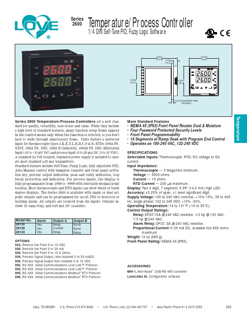
323 Temperature Series 2600温度控制器说明说明书
CALL TO ORDER: U.S. Phone 219 879-8000 • U.K. Phone (+44) (0)1494-461707 • Asia Pacific Phone 61 2 4272-2055323TemperatureSeries 2600 Temperature/Process Controllers set a new stan-dard for quality, versatility, ease-of-use and value. While they include a high level of standard features, many function setup items appear in the control menu only when the function is selected, so you don’t have to wade through unnecessary items. Units feature a universal input for thermocouple types J,K,E,T,L,N,B,C,S & R; RTDs 100Ω Plt.NIST, 100Ω Plt. DIN, 120Ω Ni Industrial, 1000Ω Plt. DIN; differential input (-10 to +10 mV DC) and process input (0 to 20 mA DC, 0 to 10 VDC).A standard 24 Volt isolated, regulated power supply is included to oper-ate most standard 4-20 mA transmitters.Standard features include Self-Tune, Fuzzy Logic, fully adjustable PID,Auto/Manual control with bumpless transfer and front panel activa-tion key, percent output indication, peak and valley indication, loop break protection and indication. For process inputs, the display is fully programmable from -1999 to +9999 with selectable decimal point location. Most thermocouple and RTD inputs can show whole or tenth degree displays. The Series 2600 is available with single or dual set-point outputs and can be programmed for on-off, PID or heat/cool or latching alarm. All outputs are isolated from the inputs. Outputs in-clude 10 Amp relay, and 0-20 mA DC (scalable).More Standard Features• NEMA 4X (IP65) Front Panel Resists Dust & Moisture • Four Password Protected Security Levels • Front Panel Programmability• 16 Segments of Ramp/Soak with Program End Control • Operates on 100-240 VAC, 132-240 VDCSPECIFICATIONSSelectable Inputs:Thermocouple, RTD, DC voltage or DC current.Input Impedance:Thermocouple — 3 Megohms minimum.Voltage — 5000 ohms. Current — 10 ohms.RTD Current — 200 µA maximum.Display:Two 4 digit, 7 segment, 0.56" (14.2 mm) high LED. Accuracy: ±0.25% of span, ±1 least significant digit.Supply Voltage: 100 to 240 VAC nominal, +10%-15%, 50 to 400Hz, single phase; 132 to 240 VDC +10% -20%.Operating Temperature:14 to 131°F (-10 to 55°C).Control Output Ratings:Relay:SPDT,10A @ 240 VAC resistive, 1/2 hp @ 120 VAC, 1/3 hp @ 240 VAC.Alarm Relay: SPST, 3A @ 240 VAC resistive.Proportional Current: 0-20 mA DC, scalable into 600 ohmsmaximum.Weight: 13 oz (369 g).Front Panel Rating:NEMA 4X (IP65).OPTIONS924, Remote Set Point 0 to 10 VDC 926, Remote Set Point 0 to 20 mA928, Remote Set Point 0 to 10 K Ohms934, Process Signal Output, Non-Isolated 0 to 20 mADC 936, Process Signal Output Non-Isolated 0 to 10 VDC992, RS-XXX Serial Communications Love Link™ Protocol 993, RS-XXX Serial Communications Love Link™ Protocol 995, RS-XXX Serial Communications Modbus ®RTV Protocol 996, RS-XXX Serial Communications Modbus ®RTV ProtocolACCESSORIESMN-1,Mini-Node ™USB/RS-485 converter LoveLinks III,Configuration software。
- 1、下载文档前请自行甄别文档内容的完整性,平台不提供额外的编辑、内容补充、找答案等附加服务。
- 2、"仅部分预览"的文档,不可在线预览部分如存在完整性等问题,可反馈申请退款(可完整预览的文档不适用该条件!)。
- 3、如文档侵犯您的权益,请联系客服反馈,我们会尽快为您处理(人工客服工作时间:9:00-18:30)。
第5章 5.1 5.2 5.3 第6章 6.1 6.2 第7章 7.1 7.2 7.3 7.4 7.4.1 7.4.2
用户调整设置 ................................. 5-1 链式装纸页首调整 ................................ 5-1 摩擦装纸页首调整 ................................ 5-2 撕纸位置调整 .................................... 5-3 故障和保养 ................................... 6-1 故障处理 ........................................ 6-1 保养与维护 ...................................... 6-6 规格 ......................................... 7-1 打印机规格 ...................................... 7-1 接口接头引脚 .................................... 7-4 字符集 ......................................... 7-11 控制码摘要表 ................................... 7-17 ESC/P和LQ仿真控制码摘要表 ...................... 7-17 OKI仿真控制码摘要表 ............................ 7-21
安装打印机 1-1
1.2 开箱和检查
打开纸箱,对照下图检查箱内部件和附件是否齐全。如果有任何 部件遗失,请与卖方联系。 注意:使用之前,请先取出打印头固定板等保护材料;请把有关保护 材料与外箱一同妥善保管,以备以后使用。
安装打印机 1-2
1.3 打印机部件
要熟悉打印机部件及功能,请参阅下一页。
安装打印机 1-3
绪 言
承蒙惠顾,购得 DS-2600II 打印机。操作手册详细阐述 了本机的性能及操作方法,能指导您正确使用。当您遇到疑 问或机器发生故障时,此手册会带给您很大的帮助。 DS-2600II 打印机是得实集团与日本西铁城公司合作开 发、生产的多功能超高速 24 针 80 列通用打印机。 DS-2600II 采用高速打印头设计,打印速度高达 200 汉字 /秒, 打印针寿命 4 亿次, 1000 万字符长寿命耐用色带, GB18030 中文大字符集硬字库及多款防改写数字、半角英数字及八款 条形码打印,使 DS-2600II 在硬件方面别具特色。 在软件方面, DS-2600II 秉承了得实系列打印机的高性能、 高兼容性,可兼容所有 STAR、EPSON 和 OKI 打印机,方便的 自动撕纸功能及参数设置功能是得实打印机的特色。 打印机针调整和断针自动补偿功能是得实打印机的专利 技术。 DS-2600II 外观时尚, 性能卓越, 功能强大, 性价比特高, 是金融、酒店、医院、连锁药店、大型超市、专卖店等各行 业用户的极佳选择。
本产品信息如有更改,恕不另行通知。 本资料仅供参考。除中国现行法律法规规定,得实集团 不承担任何由于使用本资料而造成的直接或间接损失的责 任。 得实集团保留最终解释权。
目录
第1章 1.1 1.2 1.3 1.4 1.5 1.6 1.7 第2章 2.1 2.2 2.3 2.4 2.5 第3章 3.1 3.2 3.3 3.4 第4章 4.1 4.2 4.3 4.4 4.5 4.6 4.7 4.8 4.9 4.10 安装打印机 ................................... 1-1 放置打印机 ...................................... 1-1 开箱和检查 ...................................... 1-2 打印机部件 ...................................... 1-3 安装和拆卸色带盒 ................................ 1-5 打印机和主机连接 ................................ 1-8 连接电源 ....................................... 1-10 安装打印驱动程序 ............................... 1-11 纸的安装和使用 ............................... 2-1 选纸 ............................................ 调校打印头间隙 .................................. 安装导纸板 ...................................... 使用链式纸 ...................................... 使用单页纸 ...................................... 2-1 2-1 2-3 2-4 2-8
4
第1章 安装打印机
本章描述如何安装一台新的打印机,步骤如下: 放置打印机 开箱和检查 安装和更换色带盒 连接接口电缆 连接电源 安装打印驱动程序
1.1 放置打印机
先将打印机放在将要使用的地方,清除打印机所有包装物件(这 些包装物件用于保证打印机运输时不受损坏) , 并妥善保存包装物件及 纸箱,以备后用。 在安装打印机之前,首先要确定一个合适的地方放置打印机。 这里“合适的地方”是指: 请将打印机平放在工作台上。 避免将打印机置于过热、过度潮湿和灰尘过多的地方。 接上稳定电源,避免与电冰箱之类大功率或有干扰的电器同 一电源。 关闭打印机电源开关后,才能拔插电源线,打印机应尽可能 放置在接近插座的地方,便于使用。 打印机必须放置在走纸空间足够的地方。 如果用打印机并行接口连接,必须确保电缆长度在 2 米范围 内。
参数设置 ..................................... 4-1 如何进行参数设置 ................................ 4-2 系统设置 ........................................ 4-3 纸张设置 ........................................ 4-7 接口设置 ....................................... 4-11 ESC/P和LQ仿真参数设置 .......................... 4-13 OKI仿真参数设置 ................................ 4-16 双向测试及纵向校正 ............................. 4-17 打印针自动调整设置 ............................. 4-21 打印针补偿设置 ................................. 4-22 如何恢复出厂设置 ............................... 4-24 1
附录 1:电子信息产品污染控制的说明..................... 7-1
2
安全规范
使 用 注 意 事 项
为了避免受到电击和伤害及防止损坏打印机,在接上电源之 前,务请注意以下重要事项: 仔细阅读操作手册等说明文件。 打印机必须平放在固定的台面上。 避免震动、碰撞、高温和阳光直射、灰尘等。 请勿将打印机置于潮湿的环境中, 请勿让雨水等任何液体沾湿打 印机。 打印机应安放在接近插座的地方, 方便操作者进行电源插头的拔 插操作。 确保电源的电压值与打印机所规定的电压值一致, 避免与电冰箱 等大功率或有干扰的电器同一电源。 为保证安全操作,三脚插头必须插进三孔交流电源插座中,其中 地线必须有效接地。 电源延长线必须为三芯并正确连接,以提供接地。 若交流电源插座与打印机插头不匹配, 请更换合适的交流电源插 座,以保证人员、设备的安全使用。 连接打印机通讯电缆时,请先关闭打印机和计算机的电源,选用 适合的联机电缆将打印机和计算机连接起来。 请勿接触打印头外壳,以防止高温伤害。 清洁打印机前,先关闭电源开关,从电源插座拔掉电源插头。用 软棉绒布沾少量中性清洁剂或酒精,轻抺打印机外部。 如遇打印机发生故障,除认可的合格技术员外,不可擅自进行维 修工作。
控制面板 ..................................... 3-1 按钮及其指示灯 .................................. 开机功能 ........................................ 组合功能 ........................................ 设置模式下的按钮功能 ............................ 3-1 3-3 3-6 3-8
3
企业公开信息:
1. 售后服务请致电全国各地得实服务网点电话,或拨打: 400-810-9998(手机) 800-810-9998(免费) 2. 产品能耗: 产品使用状态 工作时 操作模式功率(休眠) 待机功率(关闭) 最大能耗 91W 5.4W 0.1W 最小能耗 10W
a. 本产品符合 GB25956-2010 《打印机、 传真机能效限定值及能效等 级》一级能效等级最高要求。 b. 打印机停止使用 5 分钟(默认出厂设置) ,即自动切换到节能模 式(详见第 4 章) 。 c. 只有当产品无任何外接输入电源时,才能实现零能耗。 3. 在换气不畅的房间中长时间使用或打印大量文件时, 建议用户来电咨询, 我们将给您 详细解答。 5. 当您弃置达到使用寿命年限的针式打印机或其原装耗材时, 我们建 议您将废弃产品返还给本公司或全国各地的得实服务网点, 由得实 集团作统一处理,以保护生态环境。 6. 本产品能使用含 70%回收纤维的再生纸进行打印。在不影响使用 的情况下,为节约资源,请选择使用再生纸;请选择双面打印。
