PID控制技术的MATLAB实现
PID控制技术的MATLAB实现
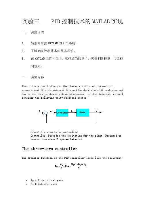
实验三一. 实验目的 1. 2. 3.PID 控制技术的 MATLAB 实现熟悉并掌握 MATLAB 的工作环境。
了解 PID 控制技术的基本理论。
在 MATLAB 工作环境下,选择适当的例子,实现 PID 控制,讨论控 制效果。
二. 实验内容This tutorial will show you the characteristics of the each of proportional (P), the integral (I), and the derivative (D) controls, and how to use them to obtain a desired response. In this tutorial, we will consider the following unity feedback system:Plant: A system to be controlled Controller: Provides the excitation for the plant; Designed to control the overall system behaviorThe threethree-term controllerThe transfer function of the PID controller looks like the following:• •Kp = Proportional gain KI = Integral gain•Kd = Derivative gainFirst, let's take a look at how the PID controller works in a closed-loop system using the schematic shown above. The variable (e) represents the tracking error, the difference between the desired input value (R) and the actual output (Y). This error signal (e) will be sent to the PID controller, and the controller computes both the derivative and the integral of this error signal. The signal (u) just past the controller is now equal to the proportional gain (Kp) times the magnitude of the error plus the integral gain (Ki) times the integral of the error plus the derivative gain (Kd) times the derivative of the error.This signal (u) will be sent to the plant, and the new output (Y) will be obtained. This new output (Y) will be sent back to the sensor again to find the new error signal (e). The controller takes this new error signal and computes its derivative and its integral again. This process goes on and on.The characteristics of P, I, and D controllersA proportional controller (Kp) will have the effect of reducing the rise time and will reduce ,but never eliminate, the steady-state error. An integral control (Ki) will have the effect of eliminating the steady-state error, but it may make the transient response worse. A derivative control (Kd) will have the effect of increasing the stability of the system, reducing the overshoot, and improving the transient response. Effects of each of controllers Kp, Kd, and Ki on a closed-loop system are summarized in the table shown below. CL RESPONSE Kp Ki Kd RISE TIME Decrease Decrease OVERSHOOT OVERSHOOT SETTLING TIME Increase Small Change Increase Increase Decrease S-S ERROR Decrease Eliminate Small ChangeSmall Change DecreaseNote that these correlations may not be exactly accurate, because Kp, Ki, and Kd are dependent of each other. In fact, changing one of these variables can change the effect of the other two. For this reason, the table should only be used as a reference when you are determining the values for Ki, Kp and Kd.三. 实验步骤 选择如下示例,按步骤进行试验:Example ProblemSuppose we have a simple mass, spring, and damper problem.The modeling equation of this system is(1) Taking the Laplace transform of the modeling equation (1)The transfer function between the displacement X(s) and the input F(s) then becomesLet• • • •M = 1kg b = 10 N.s/m k = 20 N/m F(s) = 1Plug these values into the above transfer functionThe goal of this problem is to show you how each of Kp, Ki and Kd contributes to obtain• • •Fast rise time Minimum overshoot No steady-state errorOpenOpen-loop step responseLet's first view the open-loop step response. Create a new m-file and add in the following code:num=1; den=[1 10 20]; step(num,den) Running this m-file in the Matlab command window should give you the plot shown below.The DC gain of the plant transfer function is 1/20, so 0.05 is the final value of the output to an unit step input. This corresponds to the steady-state error of 0.95, quite large indeed. Furthermore, the rise time is about one second, and the settling time is about 1.5 seconds. Let'sdesign a controller that will reduce the rise time, reduce the settling time, and eliminates the steady-state error.Proportional controlFrom the table shown above, we see that the proportional controller (Kp) reduces the rise time, increases the overshoot, and reduces the steady-state error. The closed-loop transfer function of the above system with a proportional controller is:Let the proportional gain (Kp) equals 300 and change the m-file to the following:Kp=300; num=[Kp]; den=[1 10 20+Kp]; t=0:0.01:2; step(num,den,t) Running this m-file in the Matlab command window should gives you the following plot.Note: The Matlab function called cloop can be used to obtain a closed-looptransfer function directly from the open-loop transfer function (insteadof obtaining closed-loop transfer function by hand). The following m-file uses the cloop command that should give you the identical plot as the one shown above. num=1; den=[1 10 20]; Kp=300; [numCL,denCL]=cloop(Kp*num,den); t=0:0.01:2; step(numCL, denCL,t)The above plot shows that the proportional controller reduced both the rise time and the steady-state error, increased the overshoot, and decreased the settling time by small amount.ProportionalProportional-Derivative controlNow, let's take a look at a PD control. From the table shown above, we see that the derivative controller (Kd) reduces both the overshoot and the settling time. The closed-loop transfer function of the given system with a PD controller is:Let Kp equals to 300 as before and let Kd equals 10. Enter the following commands into an m-file and run it in the Matlab command window.Kp=300; Kd=10; num=[Kd Kp]; den=[1 10+Kd 20+Kp]; t=0:0.01:2; step(num,den,t)This plot shows that the derivative controller reduced both the overshoot and the settling time, and had small effect on the rise time and the steady-state error.ProportionalProportional-Integral controlBefore going into a PID control, let's take a look at a PI control. From the table, we see that an integral controller (Ki) decreases the rise time, increases both the overshoot and the settling time, and eliminates the steady-state error. For the given system, the closed-loop transfer function with a PI control is:Let's reduce the Kp to 30, and let Ki equals to 70. Create an new m-file and enter the following commands.Kp=30; Ki=70; num=[Kp Ki]; den=[1 10 20+Kp Ki]; t=0:0.01:2; step(num,den,t) Run this m-file in the Matlab command window, and you should get the following plot.We have reduced the proportional gain (Kp) because the integral controller also reduces the rise time and increases the overshoot as the proportional controller does (double effect). The above response shows that the integral controller eliminated the steady-state error.ProportionalProportional-IntegralIntegral-Derivative controlNow, let's take a look at a PID controller. The closed-loop transfer function of the given system with a PID controller is:After several trial and error runs, the gains Kp=350, Ki=300, and Kd=50 provided the desired response. To confirm, enter the following commands to an m-file and run it in the command window. You should get the following step response. Kp=350; Ki=300; Kd=50;num=[Kd Kp Ki]; den=[1 10+Kd 20+Kp Ki]; t=0:0.01:2;step(num,den,t)Now, we have obtained the system with no overshoot, fast rise time, and no steady-state error.四.实验报告 1.综述 PID 控制的理论原理;2.画出示例程序中 PID 控制结构图,并简述控制效果;3.选择其它的示例实现 PID 控制。
matlab中pid控制器的应用实例
matlab中pid控制器的应用实例Matlab中PID控制器的应用实例引言PID控制器是一种常用的控制器,可以广泛应用于自动控制系统中。
其中,P代表比例,I代表积分,D代表微分。
PID控制器通过对误差、误差的积分和误差的微分进行加权求和,以便更好地控制系统的输出。
在本文中,我们将使用Matlab来演示PID控制器的应用实例。
我们将从控制物理实验中的水位控制系统开始,然后详细介绍PID控制器的原理和参数调整,最后使用Matlab进行仿真实验和结果分析。
一、实验背景我们考虑一个简单的水位控制系统。
系统由一个水箱和一个控制阀组成。
当水箱的水位低于设定水位时,控制阀将打开,往水箱中注水,当水位达到设定水位时,控制阀将关闭。
我们的目标是设计一个PID控制器,以便精确控制水箱中的水位。
二、PID控制器介绍在介绍PID控制器之前,我们需要了解一些基本的概念。
1. 比例控制(P)比例控制是根据误差的大小来调整控制量的大小。
比例增益参数Kp用于调整误差和控制量之间的比例关系。
控制量可通过以下公式计算:Control = Kp * Error其中,Error是设定值与测量值之间的差异。
2. 积分控制(I)积分控制用于减小系统的稳态误差。
积分增益参数Ki用于计算控制量的积分部分。
控制量可通过以下公式计算:Control = Kp * Error + Ki * \int Error dt其中,\int Error dt表示误差的积分。
3. 微分控制(D)微分控制用于减小系统的瞬态误差。
微分增益参数Kd用于计算控制量的微分部分。
控制量可通过以下公式计算:Control = Kp * Error + Ki * \int Error dt + Kd * \frac{{dError}}{{dt}}其中,\frac{{dError}}{{dt}}表示误差的微分。
三、PID控制器参数调整PID控制器中的三个参数(Kp,Ki,Kd)对控制器的性能有着重要的影响。
PID控制和其MATLAB仿真

序号,k=1,2,……,e (k-1)和e (k)分别为第(k-
1)和第k时刻所得旳偏差信号。
1.3.1 位置式PID控制算法
• 位置式PID控制系统
1.3.1 位置式PID控制算法
根据位置式PID控制算法得 到其程序框图。
在仿真过程中,可根据实 际情况,对控制器旳输出 进行限幅:[-10,10]。
• 变速积分旳基本思想是,设法变化积分项旳累加 速度,使其与偏差大小相相应:偏差越大,积分 越慢;反之则越快,有利于提升系统品质。
• 设置系数f(e(k)),它是e(k)旳函数。当 ∣e(k)∣增大时,f减小,反之增大。变速积分 旳PID积分项体现式为:
ui (k )
ki
k
1
e(i)
f
e(k )e(k )T
i0
1.3.8 变速积分算法及仿真
• 系数f与偏差目前值∣e(k)∣旳关系能够是线性 旳或是非线性旳,例如,可设为
1
f
e(k
)
A
e(k A
)
B
0
e(k) B B e(k) A B e(k) A B
1.3.8 变速积分算法及仿真
• 变速积分PID算法为:
u(k)
k
p e(k )
ki
1.3.4 增量式PID控制算法及仿真
• 增量式PID阶跃跟踪成果
1.3.5 积分分离PID控制算法及仿真
• 在一般PID控制中,引入积分环节旳目旳主要是为了 消除静差,提升控制精度。但在过程旳开启、结束或 大幅度增减设定时,短时间内系统输出有很大旳偏差 ,会造成PID运算旳积分积累,致使控制量超出执行机 构可能允许旳最大动作范围相应旳极限控制量,引起 系统较大旳振荡,这在生产中是绝对不允许旳。
控制系统pid参数整定方法的matlab仿真

控制系统PID参数整定方法的MATLAB仿真1. 引言PID控制器是一种常见的控制算法,广泛应用于自动控制系统中。
其通过调节三个参数:比例增益(Proportional gain)、积分时间常数(Integral time constant)和微分时间常数(Derivative time constant),实现对被控对象的稳态误差、响应速度和稳定性等性能指标的调节。
PID参数的合理选择对控制系统的性能至关重要。
本文将介绍PID控制器的经典整定方法,并通过MATLAB软件进行仿真,验证整定方法的有效性。
2. PID控制器的整定方法2.1 手动整定法手动整定法是根据经验和试错法来选择PID参数的方法。
具体步骤如下:1.将积分时间常数和微分时间常数设为零,仅保留比例增益,将比例增益逐渐增大直至系统产生较大的超调现象。
2.根据超调响应的情况,调整比例增益,以使系统的超调量接近所需的范围。
3.逐步增加微分时间常数,观察系统的响应速度和稳定性。
4.增加积分时间常数,以减小系统的稳态误差。
手动整定法的优点是简单易行,但需要经验和反复试验,对控制系统要求较高。
2.2 Ziegler-Nichols整定法Ziegler-Nichols整定法是一种基于试探和试错法的自整定方法,该方法通过调整系统的输入信号,观察系统的输出响应,从而确定PID参数。
具体步骤如下:1.将I和D参数设为零,仅保留P参数。
2.逐步增大P参数,直到系统的输出出现大幅度的振荡。
3.记录下此时的P参数值,记为Ku。
4.根据振荡的周期Tp,计算出系统的临界增益Kc = 0.6 * Ku。
5.根据系统的类型选择相应的整定法则:–P型系统:Kp = 0.5 * Kc,Ti = ∞,Td = 0–PI型系统:Kp = 0.45 * Kc,Ti = Tp / 1.2,Td = 0–PID型系统:Kp = 0.6 * Kc,Ti = Tp / 2,Td = Tp / 82.3 Cohen-Coon整定法Cohen-Coon整定法是基于频域曲线拟合的方法,主要应用于一阶和二阶系统的整定。
matlab实验四基于Matlab的PID控制器实验
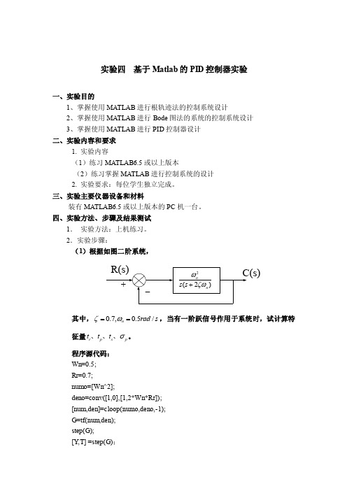
实验四 基于Matlab 的PID 控制器实验一、实验目的1、掌握使用MATLAB 进行根轨迹法的控制系统设计2、掌握使用MATLAB 进行Bode 图法的系统的控制系统设计3、掌握使用MATLAB 进行PID 控制器设计 二、实验内容和要求1. 实验内容(1)练习MATLAB6.5或以上版本(2)练习掌握MATLAB 进行控制系统的设计 2. 实验要求:每位学生独立完成。
三、实验主要仪器设备和材料装有MATLAB6.5或以上版本的PC 机一台。
四、实验方法、步骤及结果测试1. 实验方法:上机练习。
2.实验步骤:(1)根据如图二阶系统,其中,0.7,0.5/n rad s ζω==,当有一阶跃信号作用于系统时,试计算特征量r p s p t t t σ、、、。
程序源代码: Wn=0.5; Rr=0.7; numo=[Wn^2];deno=conv([1,0],[1,2*Wn*Rr]); [num,den]=cloop(numo,deno,-1); G=tf(num,den); step(G); [Y ,T] =step(G);[pos,tp,tr,ts2]=stepchar(Y,T);pos =4.7092tp =8.8343tr =4.2594ts2 =11.8317其中stepchar函数如下function [pos,tp,tr,ts2]=stepchar(y,t)%find pos and tp%返回阶跃响应输出y列向量的最大值mp及对应下标值ind [mp,ind]=max(y);%求取时间向量的长度dimtdimt=length(t);%确定最终的稳定值yssyss=y(dimt);pos=100*(mp-yss)/yss;tp=t(ind);% find rise time tr%确定输出为0.1时的时刻i=1;j=1;k=1;q=1;while y(i)<0.1i=i+1;endt1=t(i);%确定输出为0.9时的时刻 while y(j)<0.9 j=j+1; end t2=t(j); tr=t2-t1; % find ts2 i=dimt+1; n=0; while n==0 i=i-1; if i==1 n=1; elseif y(i)>=1.02 n=1; end endt1=t(i);i=dimt+1;n=0; while n==0 i=i-1; if y(i)<=0.98 n=1; end t2=t(i); if t1>t2 ts2=t1; else ts2=t2; end end(2)设被控对象的传递函数为0()(1)(0.51)kG s s s s =++试其设计要求:1v K s -=10,相角裕度为50度,幅值裕度为10dB ,试确定一个校正装置,以满足性能指标。
matlab pid控制 粒子群算法
matlab pid控制粒子群算法在控制系统设计中,PID控制器是一种常用的控制策略,它具有简单、稳定、可靠等优点。
然而,传统的PID控制器参数通常需要手动调整,这需要大量的经验和时间。
为了解决这个问题,可以使用粒子群优化(Particle Swarm Optimization,PSO)算法来自动调整PID控制器的参数。
PSO算法是一种基于群体智能的优化算法,它通过模拟鸟群、鱼群等生物群体的行为来寻找最优解。
在PSO算法中,每个解被称为一个粒子,每个粒子都有一个速度和位置。
粒子们通过比较自己的适应度和群体的适应度来更新自己的速度和位置,最终找到最优解。
将PSO算法应用于PID控制器参数调整,可以按照以下步骤进行:1.定义PID控制器的参数范围,包括比例系数(Kp)、积分系数(Ki)和微分系数(Kd)。
2.初始化粒子群,每个粒子表示一个PID控制器的参数组合。
3.计算每个粒子的适应度,适应度可以使用控制系统的性能指标来计算,如超调量、稳态误差等。
4.更新粒子的速度和位置,根据粒子的适应度和群体的适应度来更新粒子的速度和位置。
5.重复步骤3和4,直到达到停止条件,如达到预设的迭代次数或找到满足要求的最优解。
6.使用最优解作为PID控制器的参数,对控制系统进行优化。
在实际应用中,需要注意以下几点:1.定义合适的适应度函数,以评估控制系统的性能。
2.初始化粒子的速度和位置时,需要考虑参数范围和分布情况。
3.在更新粒子的速度和位置时,需要平衡全局搜索和局部搜索的能力。
4.需要根据具体的应用场景和要求来确定停止条件和最优解的评估标准。
5.需要考虑控制系统的约束条件和系统的稳定性。
综上所述,将粒子群优化算法应用于PID控制器参数调整是一种有效的优化方法。
通过使用粒子群优化算法,可以自动调整PID控制器的参数,提高控制系统的性能和稳定性。
在实际应用中,需要根据具体的应用场景和控制要求来确定算法的参数和最优解的评估标准。
用MATLAB对PID控制做简单的仿真

⽤MATLAB 对PID 控制做简单的仿真PID 控制是⽬前⼯程上应⽤最⼴的⼀种控制⽅法,其结构简单,且不依赖被控对象模型,控制所需的信息量也很少,因⽽易于⼯程实现,同时也可获得较好的控制效果。
PID 控制是将误差信号e(t)的⽐例(P),积分(I)和微分(D)通过线性组合构成控制量进⾏控制,其输出信号为:下⾯⽤MATLAB 软件对PID 控制做简单的仿真描述。
1. 建⽴⼆阶负反馈控制系统,其开环传递函数为:clc; clear all; close all;Go = tf(1,conv([2,1],[5,1]));2. ⽐例控制,输出与输⼊偏差成⽐例,即直接将误差信号放⼤或缩⼩。
⽐例控制的传递函数为:取不同的⽐例系数,绘制系统的单位阶跃响应曲线:Kp = [0.5,2,5,10];for m = 1:4 sys = feedback(Kp(m)*Go,1); step(sys); hold on;end随着K P 值的增⼤,系统响应速度加快,但系统的超调也随着增加,调节时间也随着增长。
当K P 增⼤到⼀定值后,闭环系统将趋于不稳定。
⽐例控制具有抗⼲扰能⼒强、控制及时、过渡时间短的优点,但存在稳态误差,增⼤⽐例系数可提⾼系统的开环增益,减⼩系统的稳态误差,从⽽提⾼系统的控制精度,但这会降低系统的相对稳定性,甚⾄可能造成闭环系统的不稳定,因此,在系统校正和设计中,⽐例控制⼀般不单独使⽤。
3. 微分控制,输出与输⼊偏差的微分成⽐例,即与偏差的变化速度成⽐例。
微分控制(与⽐例控制同时使⽤)的传递函数为:取不同的微分系数,绘制系统的单位阶跃响应曲线:Kp = 10;u(t)=[e(t)+e(t)dt +]K P 1T I ∫t 0T D de(t)dt(s)=G O 1(2s +1)(5s +1)(s)=G C K P(s)=(1+s)G C K P T DTd = [0,0.4,1,4];for m = 1:4 G1 = tf([Kp*Td(m),Kp],[0,1]); sys = feedback(G1*Go,1); step(sys); hold on;end随着T D 值的增⼤,系统超调量逐渐减⼩,动态特征有改善。
基于MATLAB的数字PID直流电机调速系统
基于MATLAB的数字PID直流电机调速系统本文主要研究基于MATLAB的数字PID直流电机调速系统。
直流电机是工业生产中常用的电机,其调速系统对于保证生产效率和质量至关重要。
因此,研究直流电机调速系统的控制方法和参数设计具有重要意义。
本文将首先介绍直流电机的数学模型和调速系统的工作原理,然后探讨常规PID控制器的设计方法和参数控制原理,最后通过MATLAB仿真实验来研究数字PID控制器的设计和应用。
2 直流电机调速系统的数学模型直流电机是一种常见的电动机,其数学模型可以用电路方程和动力学方程来描述。
电路方程描述了电机的电气特性,动力学方程描述了电机的机械特性。
通过这两个方程可以得到直流电机的数学模型,为后续的控制器设计提供基础。
3 直流电机调速系统的工作原理直流电机调速系统是通过控制电机的电压和电流来改变电机的转速。
其中,电压和电流的控制可以通过PWM技术实现。
此外,还可以通过变换电机的电极连接方式来改变电机的转速。
直流电机调速系统的工作原理是控制电机的电压和电流,从而控制电机的转速。
4 常规PID控制器的设计方法和参数控制原理常规PID控制器是一种常见的控制器,其控制原理是通过比较实际输出值和期望输出值来调整控制器的参数,从而实现控制目标。
常规PID控制器的参数包括比例系数、积分系数和微分系数,这些参数的选取对于控制器的性能有重要影响。
常规PID控制器的设计方法是通过试错法和经验公式来确定参数值。
5 数字PID控制器的设计和应用数字PID控制器是一种数字化的PID控制器,其优点是精度高、可靠性强、适应性好。
数字PID控制器的设计方法是通过MATLAB仿真实验来确定控制器的参数值。
数字PID控制器在直流电机调速系统中的应用可以提高系统的控制精度和稳定性。
6 结论本文主要研究了基于MATLAB的数字PID直流电机调速系统,介绍了直流电机的数学模型和调速系统的工作原理,探讨了常规PID控制器的设计方法和参数控制原理,最后研究了数字PID控制器的设计和应用。
基于MATLAB的PID控制器设计
基于MATLAB的PID 控制器设计基于MATLAB的PID 控制器设计一、PID控制简介PID控制是最早发展起来的经典控制策略, 是用于过程控制最有效的策略之一。
由于其原理简单、技术成,在实际应用中较易于整定, 在工业控制中得到了广泛的应用。
它最大的优点是不需了解被控对象精确的数学模型,只需在线根据系统误差及误差的变化率等简单参数, 经过经验进行调节器参数在线整定, 即可取得满意的结果, 具有很大的适应性和灵活性。
积分作用:可以减少稳态误差, 但另一方面也容易导致积分饱和, 使系统的超调量增大。
微分作用:可提高系统的响应速度, 但其对高频干扰特别敏感, 甚至会导致系统失稳。
所以, 正确计算控制器的参数, 有效合理地实现PID控制器的设计,对于PID 控制器在过程控制中的广泛应用具有重要的理论和现实意义。
在PID控制系统中, PID控制器分别对误差信号e(t)进行比例、积分与微分运算, 其结果的加权和构成系统的控制信号u(t),送给对象模型加以控制。
PID控制器的数学描述为其传递函数可表示为:从根本上讲, 设计PID控制器也就是确定其比例系数Kp、积分系数T i 和微分系数T d , 这三个系数取值的不同, 决定了比例、积分和微分作用的强弱。
控制系统的整定就是在控制系统的结构已经确定、控制仪表和控制对象等处在正常状态的情况下, 适当选择控制器参数使控制仪表的特性和控制对象的特性相配合, 从而使控制系统的运行达到最佳状态, 取得最好的控制效果。
二、MATLAB的Ziegler-Nichols算法PID控制器设计。
1、PID控制器的Ziegler-Nichols参数整定在实际的过程控制系统中, 有大量的对象模型可以近似地由一阶模型来表示。
这个对象模型可以表示为sL-esT1KG(s)+=如果不能建立起系统的物理模型, 可通过试验测取对象模型的阶跃响应, 从而得到模型参数。
当然, 我们也可在已知对象模型的情况下, 利用MATLAB,通过使用step ( ) 函数得到对象模型的开环阶跃响应曲线。
模糊pidmatlab(simulink)仿真详细步骤
下面用一个简单的例子作介绍:(本例不是特别针对实现什么功能,只是为了介绍方便)第一部分创建一个模糊逻辑(.fis文件)第一步:打开模糊推理系统编辑器步骤:在Commond Window 键入fuzzy回车打开如下窗口,既模糊推理系统编辑器第二步:使用模糊推理系统编辑器本例用到两个输入,两个输出,但默认是一个输人,一个输出步骤:1、添加一个输入添加一个输出得如下图2、选择Input、output(选中为红框),在Name框里修改各输入的名称并将And method 改为prod,将Or method 改为probor提示:在命名时’_’在显示时为下标,可从上图看出。
第三步:使用隶属函数编辑器该编辑器提供一个友好的人机图形交互环境,用来设计和修改模糊推理系中各语言变量对应的隶属度函数的相关参数,如隶属度函数的形状、范围、论域大小等,系统提供的隶属度函数有三角、梯形、高斯形、钟形等,也可用户自行定义。
步骤:1、双击任何一个输入量(In_x、In_y)或输出量打开隶属度函数编辑器。
2、在左下处Range和Display Range处添加取值范围,本例中In_x和In_y的取值范围均为[0 10], Out_x和Out_y的取值范围均为[0 1]3、默认每个输入输出参数中都只有3个隶属度函数,本例中每个输入输出参数都需要用到五个,其余几个需要自己添加:选中其中一个输入输出参数点击Edit菜单,选Add MFS…打开下列对话框将MF type设置为trimf(三角形隶属度函数曲线,当然你也需要选择其他类型) 将Number of MFs设置为2点击OK按钮同样给其他三个加入隶属度函数4、选中任何一个隶属度函数(选中为红色),在Name中键入名称,在Type 中选择形状,在Params中键入范围,然后回车如下图:5、关闭隶属函数编辑器第四步:使用规则编辑器通过隶规则编辑器来设计和修改“IF...THEN”形式的模糊控制规则。
PID控制算法的matlab仿真

PID 控制算法的matlab 仿真PID 控制算法是实际工业控制中应用最为广泛的控制算法,它具有控制器设计简单,控制效果好等优点。
PID 控制器参数的设置是否合适对其控制效果具有很大的影响,在本课程设计中一具有较大惯性时间常数和纯滞后的一阶惯性环节作为被控对象的模型对PID 控制算法进行研究。
被控对象的传递函数如下:()1d sf Ke G s T sτ-=+ 其中各参数分别为30,630,60f d K T τ===。
MATLAB 仿真框图如图1所示。
1Out1Zero-Order HoldTransport Delay30630s+1Transfer FcnStep-K-Kp-K-Ki-K-Kdz (z-1)(z-1)zAdd图12 具体内容及实现功能2.1 PID 参数整定PID 控制器的控制参数对其控制效果起着决定性的作用,合理设置控制参数是取得较好的控制效果的先决条件。
常用的PID 参数整定方法有理论整定法和实验整定法两类,其中常用的实验整定法由扩充临界比例度法、试凑法等。
在此处选用扩充临界比例度法对PID 进行整定,其过程如下:1) 选择采样周期 由于被控对象中含有纯滞后,且其滞后时间常数为60d τ=,故可选择采样周期1s T =。
2) 令积分时间常数i T =∞,微分时间常数0d T =,从小到大调节比例系数K ,使得系统发生等幅震荡,记下此时的比例系数k K 和振荡周期k T 。
3) 选择控制度为 1.05Q =,按下面公式计算各参数:0.630.490.140.014p k i k d k s kK K T T T T T T ====通过仿真可得在1s T =时,0.567,233k k K T ==,故可得:0.357,114.17,32.62, 3.262p i d s K T T T ====0.0053.57p s i i p d d sK T K T K T K T ====按此组控制参数得到的系统阶跃响应曲线如图2所示。
pid控制及其matlab仿真-详细

在MATLAB中搭建仿真模型,验证PID控制器对复杂系统的控制 效果。
PID控制器的参数优化
参数优化方法
采用智能优化算法(如遗传算法、粒子群算法等)对PID 控制器参数进行优化,以进一步提高控制性能。
01
MATLAB实现
在MATLAB中编写优化算法程序,通过 Simulink仿真模型进行测试和验证。
积分控制
02
03
微分控制
通过累积输入信号的变化量来控 制输出信号,以减小输出信号的 误差。
通过预测输入信号的变化趋势来 控制输出信号,以减小输出信号 的超调和响应时间。
PID控制器的参数整定
比例系数
影响控制器的增益,比例系数越 大,控制器的增益越大,输出信 号变化越快。
积分系数
影响积分控制的强度,积分系数 越大,积分控制作用越强,误差 减小越快。
温度控制系统中的应用
温度控制系统是PID控制器的另一个重要应用领域。在工 业和科学实验中,温度控制对于保持恒定的实验条件和产 品质量至关重要。
PID控制器用于温度控制系统的目的是通过自动调节加热 元件的功率或冷却介质的流量,将温度维持在设定的范围 内。
PID控制器通过比较温度传感器的实际测量值与期望值之 间的误差,来调整加热元件或冷却介质的控制信号,以减 小误差并实现稳定的温度控制。
pid控制及其 matlab仿真-详细
目 录
• PID控制理论简介 • MATLAB仿真环境介绍 • PID控制器在MATLAB中的实现 • PID控制器的性能分析 • PID控制器的应用实例 • 结论与展望
01
CATALOGUE
PID控制理论简介
增量式PID的MATLAB实现
增量式PID的MATLAB实现增量式PID(Proportional-Integral-Derivative)控制是一种经典的控制算法,它通过识别并调整系统的误差,以达到期望的控制效果。
与位置式PID控制相比,增量式PID控制具有较好的实时性和鲁棒性。
下面介绍如何使用MATLAB实现增量式PID控制。
首先,需要明确增量式PID控制的数学模型。
假设控制系统的误差为e(t),增量式PID控制的控制输出为u(t),则控制器可以表示为以下形式:u(t)=u(t-1)+Kp*(e(t)-e(t-1))+Ki*e(t)+Kd*(e(t)-2*e(t-1)+e(t-2))其中,Kp、Ki和Kd分别为增量式PID控制的比例、积分和微分参数。
e(t)-e(t-1)表示当前时刻的误差与上一时刻误差之差,e(t)-2*e(t-1)+e(t-2)表示当前时刻误差与前两个时刻误差的差值。
下面开始实现增量式PID控制的MATLAB代码。
首先,定义控制器的比例、积分和微分参数:```matlabKp=1;Ki=0.5;Kd=0.2;```然后,定义控制器的初始误差和控制输出:```matlabe=0;u=0;```接着,开始进行增量式PID控制。
在每个采样周期内,首先获取当前的误差:```matlabe_current = ...; % 获取当前的误差```接下来,根据增量式PID控制的公式计算控制输出的增量:```matlabdelta_u = Kp * (e_current - e) + Ki * e_current + Kd *(e_current - 2*e + e_prev);```然后,将增量式控制输出的增量与前一时刻的输出进行累加,得到当前时刻的控制输出:```matlabu = u + delta_u;```最后,更新误差的值:```matlabe_prev = e;e = e_current;```根据上述代码,可以实现一个简单的增量式PID控制器。
基于MATLAB的PID 控制器设计

基于MATLAB的PID 控制器设计基于MATLAB 的PID 控制器设计一、PID 控制简介PID 控制是最早发展起来的经典控制策略, 是用于过程控制最有效的策略之一。
由于其原理简单、技术成,在实际应用中较易于整定, 在工业控制中得到了广泛的应用。
它最大的优点是不需了解被控对象精确的数学模型,只需在线根据系统误差及误差的变化率等简单参数, 经过经验进行调节器参数在线整定, 即可取得满意的结果, 具有很大的适应性和灵活性。
积分作用:可以减少稳态误差, 但另一方面也容易导致积分饱和, 使系统的超调量增大。
微分作用:可提高系统的响应速度, 但其对高频干扰特别敏感, 甚至会导致系统失稳。
所以, 正确计算控制器的参数, 有效合理地实现 PID 控制器的设计,对于PID 控制器在过程控制中的广泛应用具有重要的理论和现实意义。
在PID 控制系统中, PID 控制器分别对误差信号e (t )进行比例、积分与微分运算, 其结果的加权和构成系统的控制信号u (t ),送给对象模型加以控制。
PID 控制器的数学描述为其传递函数可表示为:从根本上讲, 设计PID 控制器也就是确定其比例系数Kp 、积分系数T i 和微分系数T d , 这三个系数取值的不同, 决定了比例、积分和微分作用的强弱。
控制系统的整定就是在控制系统的结构已经确定、控制仪表和控制对象等处在正常状态的情况下, 适当选择控制器参数使控制仪表的特性和控制对象的特性相配合, 从而使控制系统的运行达到最佳状态, 取得最好的控制效果。
二、M ATLAB 的 Ziegler-Nichols 算法PID 控制器设计。
1、PID 控制器的Ziegler-Nichols 参数整定在实际的过程控制系统中, 有大量的对象模型可以近似地由一阶模型来表示。
这个对象模型可以表示为sL-esT1K G(s)+=如果不能建立起系统的物理模型, 可通过试验测取对象模型的阶跃响应, 从而得到模型参数。
离散电机pid控制及其matlab仿真

03
在Simulink中构建PID控制器模型,包括比例、积分
和微分三个环节。
pid控制器仿真实现
01
PID控制器参数设置
根据控制要求,设置PID控制器 的比例、积分和微分系数,以及 采样时间等参数。
02
控制器输出与电机 响应
将PID控制器与离散电机模型连 接,观察电机响应与控制器输出 的关系。
03
电流式pid控制算法
电流式pid控制算法原理
电流式pid控制算法是根据电机电流的反馈信号来控制电机的旋转 扭矩。
电流传感器
在电流式pid控制系统中,需要使用电流传感器来检测电机的电流 ,并将电流信号转换为电信号。
控制逻辑
根据反馈信号和设定值之间的差异,通过pid控制算法计算出控制 输入,以调整电机的旋转扭矩。
MATLAB仿真实现
使用MATLAB的Simulink工具箱,搭建PID控制器模型,对伺服系 统进行控制仿真。
THANKS。
02
03
比例(P)控制
通过调节输入信号的幅值 ,以改变输出值的大小。
积分(I)控制
通过累计输入信号的幅值 ,以调节输出值的趋势。
微分(D)控制
通过比较输入信号的变化 率,以预调节输出值的变 化趋势。
离散电机pid控制器设计
选择合适的pid控制器
根据电机特性和控制要求,选择合适的pid控制器。
确定pid参数
基于模糊逻辑的控制器设计
模糊逻辑是一种基于模糊集合理论的智能控制方 法,适用于处理不确定性和非线性的系统。
基于模糊逻辑的控制器设计方法包括:模糊化、 规则库、反模糊化等步骤,可以根据系统的输入 和输出信息来调整pid控制器的参数,以实现更好 的控制效果。
pid控制算法 matlab
PID控制算法在Matlab中的应用1. 简介PID控制算法是一种经典控制算法,它通过比例、积分和微分三个部分来调节控制系统的输出,以实现对系统的稳定控制。
在Matlab中,可以利用其丰富的工具箱和编程功能来实现PID控制算法,并对系统进行仿真和分析。
2. PID控制算法原理PID控制算法是由比例项(P)、积分项(I)和微分项(D)组成的。
比例项根据当前误差进行控制,积分项根据累积误差进行控制,微分项则根据误差变化速度进行控制。
通过这三个部分的调节,PID控制算法可以有效地实现对系统的稳定控制。
3. 在Matlab中实现PID控制算法在Matlab中,可以利用Control System Toolbox提供的函数和工具来实现PID控制算法。
可以使用pid函数创建一个PID控制器对象,设置其比例、积分和微分系数。
可以将该PID控制器对象与系统模型进行连接,通过sim函数对系统进行仿真和分析。
4. 使用示例以下是一个简单的示例来演示如何在Matlab中实现PID控制算法。
创建一个一阶惯性系统模型,然后使用pid函数创建一个PID控制器对象,设置其比例、积分和微分系数。
将PID控制器对象与系统模型进行连接,通过sim函数对系统进行仿真并绘制响应曲线。
```matlab创建一阶惯性系统模型sys = tf(1, [1 1]);创建PID控制器对象Kp = 1;Ki = 0.1;Kd = 0.2;pid_controller = pid(Kp, Ki, Kd);将PID控制器对象与系统模型进行连接sys_with_pid = feedback(pid_controller * sys, 1);对系统进行仿真并绘制响应曲线t = 0:0.1:10;u = ones(size(t));lsim(sys_with_pid, u, t);```通过以上示例,可以看到PID控制算法对系统的控制效果。
在实际应用中,可以根据具体系统的特性和需求来调节PID控制器的参数,以达到最佳的控制效果。
基于matlabsimulink的pid控制器设计
基于matlabsimulink的pid控制器设计1.引言1.1 概述概述部分:PID控制器是一种常用的控制算法,它通过不断地调整系统的输出来使其尽量接近所期望的目标值。
在工业控制领域,PID控制器被广泛应用于各种工艺过程和自动化系统中。
本文将以MATLAB/Simulink为工具,探讨基于PID控制器的设计方法。
PID控制器以其简单易实现、稳定性好的特点,成为许多控制系统的首选。
在文章的正文部分,我们将对PID控制器的基本原理进行详细介绍,并结合MATLAB/Simulink的应用,展示如何使用这一工具来设计和实现PID控制器。
在控制系统设计中,PID控制器通过测量系统的误差,即期望输出值与实际输出值之间的差异,并根据三个控制参数:比例项(Proportional)、积分项(Integral)和微分项(Derivative)来调整系统的输出。
比例项控制系统的响应速度,积分项消除系统的稳态误差,微分项抑制系统的震荡。
MATLAB/Simulink作为一款功能强大的仿真软件,提供了丰富的控制系统设计工具。
它不仅可以帮助我们直观地理解PID控制器的工作原理,还可以实时地模拟和分析系统的响应。
通过使用MATLAB/Simulink,我们可以轻松地进行PID控制器参数调整、系统性能评估和控制算法的优化。
总之,本文旨在介绍基于MATLAB/Simulink的PID控制器设计方法,通过理论介绍和实例演示,帮助读者深入理解PID控制器的原理和应用,并为读者在实际工程项目中设计和实施PID控制器提供参考。
在结论部分,我们将总结所得结论,并对未来进一步研究的方向进行展望。
文章结构部分的内容可以描述文章的整体架构和各个部分的内容大纲。
以下是对文章1.2部分的内容补充:1.2 文章结构本文主要由以下几个部分构成:第一部分是引言部分,包括概述、文章结构和目的等内容。
在概述中,将简要介绍PID控制器在自动控制领域的重要性和应用背景。
毕业设计--基于MATLAB的PID控制算法的实现
摘要目前工业自动化水平已成为衡量各行各业现代化水平的一个重要标志。
PID 控制及其控制器已在工程实际中得到了广泛的应用。
本文介绍了PID控制的基础知识和工作原理,并讨论PID控制器的类型以及各种控制器的优缺点,为进行数字PID的算法研究和仿真提供理论基础。
在简单介绍工业过程控制中经常使用到的位置式和增量式PID控制后主要讨论了两种改进的数字PID控制算法:积分分离PID算法与不完全微分PID算法,比较传统控制算法与改进的算法的优缺点,并基于MATLAB对其进行仿真,讨论仿真结果。
仿真结果表明:积分分离控制算法和不完全微分控制算法可以提高控制精度和消除系统高频干扰等。
证明改进的PID控制算法相比一般PID控制算法有很多优点。
关键词:数字PID;积分分离;不完全微分;MATLAB仿真AbstractAt present the level of industrial automation has become an important sign of the modernization of every industries.PID control and controllers now have been worked in a wide range of engineering applications.This paper briefly introduces and discusses the types and the advantages or disadvantages of the PID controllers.These konwledge lay the foundation for the arithmetical research and the simulation.It mainly discusses two improved PID control algorithms: Integral separation PID control algorithm and Not completely differential PID control algorithm after introducing the Incremental PID control and the Position control algorithm used in the industrial process paring the advantage and diadvantage of the traditional PID control algorithm to the improved PID control algorithm and discussing the results of MATLAB simulation.The simulation results show that the Integral separation PID control algorithm and Not completely differential PID control algorithm can improve the control accuracy and eliminate the high frequency interference ,etc.This article proves that the improved PID control algorithm have more advantages than normal PID control algorithm.Key words:digital PID; Integral separation; Not completely differential simulation; MATLAB simulation目录第1章概述 (1)1.1设计的目的和意义 (1)1.2国内外研究发展现状 (1)1.3本次设计的研究内容 (2)第2章 PID控制基本理论 (3)2.1PID的工作原理 (3)2.2PID控制器类型分类 (4)2.4PID控制器参数确定 (6)2.5PID控制器优缺点 (10)2.6本章小结 (10)第3章数字PID控制算法及仿真意义 (11)3.1数字PID控制算法 (11)3.2MATLAB简介 (19)3.3PID仿真的意义 (21)3.4本章小结 (22)第4章改进型PID控制算法及仿真 (23)4.1积分分离式PID控制算法 (23)4.2不完全微分PID控制算法 (27)4.3本章小结 (32)结论 (33)参考文献 (34)致谢 (35)附录 (36)第1章概述1.1 设计的目的和意义PID控制由于结构简单、工作稳定、鲁棒性好等因素在当今的工业过程控制中仍占有主导地位。
MATLAB和基本PID控制系仿真
3.2 PID控制系统仿真
例:基本PID控制SIMULINK仿真
仿真时取kp=60,ki=1,kd=3,输入指令为rin(k)=sin(0.4*pi*t) 采用ODE45迭代措施,仿真时间为10s。
Signal Generator
Sum
PID
PID Controller
133 s2+25 s Transfer Fcn
措施一
clear all;
close all;
ts=0.001;
sys=tf(523407,[1,86.85,10465,0]);
dsys=c2d(sys,ts,'z');
[num,den]=tfdata(dsys,'v');
u_1=0.0;u_2=0.0;u_3=0.0;
y_1=0.0;y_2=0.0;y_3=0.0;
Mux
Mux
Scope
参数设置
仿真曲线
3.2.1 数字PID
1、离散系统旳数字PID控制仿真:
离散PID控制算法:
u (k )
k perror(k) ki
k
error( j)T
j0
kd
error(k) error(k T
1)
例:被控对象为:G(s)
523407
s3 86.85s 2 10465s
(5)从频域角度来看,PID控制是经过积分作用于系统旳 低频段,以提升系统旳稳态性能,而微分作用于系统旳中 频段,以改善系统旳动态性能。
Байду номын сангаас
PID参数整定规律
几条基本旳PID参数整定规律: (1)增大百分比系数一般将加紧系统旳响应,在有静差旳情
matlab simulink pid参数设定技巧
matlab simulink pid参数设定技巧
在Simulink中进行PID参数设定时,可以采用以下技巧:
1. 使用PID自动调节工具箱:Simulink提供了PID自动调节工具箱,可以根据系统的特性自动计算PID参数。
使用该工具
箱可以简化参数设定过程,提高调节效果。
2. 使用试控制法:试控制法是一种通过观察系统响应来调节PID参数的方法。
可以通过设置比例增益Kp,观察系统的响
应特性,根据实际需求调整Kp的大小。
3. 逐步调节参数:可以通过逐步调节参数的方式获取最佳结果。
首先调节比例增益Kp,观察系统响应;然后调节积分时间Ti,观察系统稳态误差;最后调节微分时间Td,观察系统对变化
的响应。
4. 增加反馈路径:在PID控制器中增加反馈路径,可以减小
系统误差。
可以使用仿真结果和实验数据来进行参数调整,并优化PID参数。
5. 使用频域分析:通过分析系统的频域特性,可以更好地调节PID参数。
可以使用Bode图来观察系统的稳定性和幅频响应
特性,调整PID参数以获得更好的控制效果。
6. 考虑系统时间常数:系统的时间常数是影响PID参数设定
的重要因素之一。
根据具体的系统响应特性,合理选择PID
参数的大小和调整范围。
7. 进行参数整定实验:通过设计合适的实验,观察系统响应,可以更准确地确定PID参数。
可以通过改变输入信号的大小、频率等,观察系统的稳态误差、超调量等指标,调整PID参
数以达到设计要求。
- 1、下载文档前请自行甄别文档内容的完整性,平台不提供额外的编辑、内容补充、找答案等附加服务。
- 2、"仅部分预览"的文档,不可在线预览部分如存在完整性等问题,可反馈申请退款(可完整预览的文档不适用该条件!)。
- 3、如文档侵犯您的权益,请联系客服反馈,我们会尽快为您处理(人工客服工作时间:9:00-18:30)。
实验三一. 实验目的 1. 2. 3.PID 控制技术的 MATLAB 实现熟悉并掌握 MATLAB 的工作环境。
了解 PID 控制技术的基本理论。
在 MATLAB 工作环境下,选择适当的例子,实现 PID 控制,讨论控 制效果。
二. 实验内容This tutorial will show you the characteristics of the each of proportional (P), the integral (I), and the derivative (D) controls, and how to use them to obtain a desired response. In this tutorial, we will consider the following unity feedback system:Plant: A system to be controlled Controller: Provides the excitation for the plant; Designed to control the overall system behaviorthreeThe three-term controllerThe transfer function of the PID controller looks like the following:• •Kp = Proportional gain KI = Integral gain•Kd = Derivative gainFirst, let's take a look at how the PID controller works in a closed-loop system using the schematic shown above. The variable (e) represents the tracking error, the difference between the desired input value (R) and the actual output (Y). This error signal (e) will be sent to the PID controller, and the controller computes both the derivative and the integral of this error signal. The signal (u) just past the controller is now equal to the proportional gain (Kp) times the magnitude of the error plus the integral gain (Ki) times the integral of the error plus the derivative gain (Kd) times the derivative of the error.This signal (u) will be sent to the plant, and the new output (Y) will be obtained. This new output (Y) will be sent back to the sensor again to find the new error signal (e). The controller takes this new error signal and computes its derivative and its integral again. This process goes on and on.The characteristics of P, I, and D controllersA proportional controller (Kp) will have the effect of reducing the rise time and will reduce ,but never eliminate, the steady-state error. An integral control (Ki) will have the effect of eliminating the steady-state error, but it may make the transient response worse. A derivative control (Kd) will have the effect of increasing the stability of the system, reducing the overshoot, and improving the transient response. Effects of each of controllers Kp, Kd, and Ki on a closed-loop system are summarized in the table shown below. CL RESPONSE Kp Ki Kd RISE TIME Decrease Decrease OVERSHOOT OVERSHOOT SETTLING TIME Increase Small Change Increase Increase Decrease S-S ERROR Decrease Eliminate Small ChangeSmall Change DecreaseNote that these correlations may not be exactly accurate, because Kp, Ki, and Kd are dependent of each other. In fact, changing one of these variables can change the effect of the other two. For this reason, the table should only be used as a reference when you are determining the values for Ki, Kp and Kd.三. 实验步骤 选择如下示例,按步骤进行试验:Example ProblemSuppose we have a simple mass, spring, and damper problem.The modeling equation of this system is(1) Taking the Laplace transform of the modeling equation (1)The transfer function between the displacement X(s) and the input F(s) then becomesLet• • • •M = 1kg b = 10 N.s/m k = 20 N/m F(s) = 1Plug these values into the above transfer functionThe goal of this problem is to show you how each of Kp, Ki and Kd contributes to obtain• • •Fast rise time Minimum overshoot No steady-state errorOpenOpen-loop step responseLet's first view the open-loop step response. Create a new m-file and add in the following code:num=1; den=[1 10 20]; step(num,den) Running this m-file in the Matlab command window should give you the plot shown below.The DC gain of the plant transfer function is 1/20, so 0.05 is the final value of the output to an unit step input. This corresponds to the steady-state error of 0.95, quite large indeed. Furthermore, the rise time is about one second, and the settling time is about 1.5 seconds. Let'sdesign a controller that will reduce the rise time, reduce the settling time, and eliminates the steady-state error.Proportional controlFrom the table shown above, we see that the proportional controller (Kp) reduces the rise time, increases the overshoot, and reduces the steady-state error. The closed-loop transfer function of the above system with a proportional controller is:Let the proportional gain (Kp) equals 300 and change the m-file to the following:Kp=300; num=[Kp]; den=[1 10 20+Kp]; t=0:0.01:2; step(num,den,t) Running this m-file in the Matlab command window should gives you the following plot.Note: The Matlab function called cloop can be used to obtain a closed-looptransfer function directly from the open-loop transfer function (insteadof obtaining closed-loop transfer function by hand). The following m-file uses the cloop command that should give you the identical plot as the one shown above. num=1; den=[1 10 20]; Kp=300; [numCL,denCL]=cloop(Kp*num,den); t=0:0.01:2; step(numCL, denCL,t)The above plot shows that the proportional controller reduced both the rise time and the steady-state error, increased the overshoot, and decreased the settling time by small amount.ProportionalProportional-Derivative controlNow, let's take a look at a PD control. From the table shown above, we see that the derivative controller (Kd) reduces both the overshoot and the settling time. The closed-loop transfer function of the given system with a PD controller is:Let Kp equals to 300 as before and let Kd equals 10. Enter the following commands into an m-file and run it in the Matlab command window.Kp=300; Kd=10; num=[Kd Kp]; den=[1 10+Kd 20+Kp]; t=0:0.01:2; step(num,den,t)This plot shows that the derivative controller reduced both the overshoot and the settling time, and had small effect on the rise time and the steady-state error.ProportionalProportional-Integral controlBefore going into a PID control, let's take a look at a PI control. From the table, we see that an integral controller (Ki) decreases the rise time, increases both the overshoot and the settling time, and eliminates the steady-state error. For the given system, the closed-loop transfer function with a PI control is:Let's reduce the Kp to 30, and let Ki equals to 70. Create an new m-file and enter the following commands.Kp=30; Ki=70; num=[Kp Ki]; den=[1 10 20+Kp Ki]; t=0:0.01:2; step(num,den,t) Run this m-file in the Matlab command window, and you should get the following plot.We have reduced the proportional gain (Kp) because the integral controller also reduces the rise time and increases the overshoot as the proportional controller does (double effect). The above response shows that the integral controller eliminated the steady-state error.Proportional-IntegralProportional-Integral-Derivative controlNow, let's take a look at a PID controller. The closed-loop transfer function of the given system with a PID controller is:After several trial and error runs, the gains Kp=350, Ki=300, and Kd=50 provided the desired response. To confirm, enter the following commands to an m-file and run it in the command window. You should get the following step response. Kp=350; Ki=300; Kd=50;num=[Kd Kp Ki]; den=[1 10+Kd 20+Kp Ki]; t=0:0.01:2;step(num,den,t)Now, we have obtained the system with no overshoot, fast rise time, and no steady-state error.四.实验报告 1.综述 PID 控制的理论原理;2.画出示例程序中 PID 控制结构图,并简述控制效果;3.选择其它的示例实现 PID 控制。
